EP4501486A1 - Method for manufacturing stabilizer, and base material - Google Patents
Method for manufacturing stabilizer, and base material Download PDFInfo
- Publication number
- EP4501486A1 EP4501486A1 EP23779723.8A EP23779723A EP4501486A1 EP 4501486 A1 EP4501486 A1 EP 4501486A1 EP 23779723 A EP23779723 A EP 23779723A EP 4501486 A1 EP4501486 A1 EP 4501486A1
- Authority
- EP
- European Patent Office
- Prior art keywords
- hole
- recess
- base material
- stabilizer
- manufacturing
- Prior art date
- Legal status (The legal status is an assumption and is not a legal conclusion. Google has not performed a legal analysis and makes no representation as to the accuracy of the status listed.)
- Pending
Links
Images


Classifications
-
- B—PERFORMING OPERATIONS; TRANSPORTING
- B21—MECHANICAL METAL-WORKING WITHOUT ESSENTIALLY REMOVING MATERIAL; PUNCHING METAL
- B21J—FORGING; HAMMERING; PRESSING METAL; RIVETING; FORGE FURNACES
- B21J5/00—Methods for forging, hammering, or pressing; Special equipment or accessories therefor
- B21J5/06—Methods for forging, hammering, or pressing; Special equipment or accessories therefor for performing particular operations
- B21J5/10—Piercing billets
-
- B—PERFORMING OPERATIONS; TRANSPORTING
- B60—VEHICLES IN GENERAL
- B60G—VEHICLE SUSPENSION ARRANGEMENTS
- B60G21/00—Interconnection systems for two or more resiliently-suspended wheels, e.g. for stabilising a vehicle body with respect to acceleration, deceleration or centrifugal forces
- B60G21/02—Interconnection systems for two or more resiliently-suspended wheels, e.g. for stabilising a vehicle body with respect to acceleration, deceleration or centrifugal forces permanently interconnected
- B60G21/04—Interconnection systems for two or more resiliently-suspended wheels, e.g. for stabilising a vehicle body with respect to acceleration, deceleration or centrifugal forces permanently interconnected mechanically
- B60G21/05—Interconnection systems for two or more resiliently-suspended wheels, e.g. for stabilising a vehicle body with respect to acceleration, deceleration or centrifugal forces permanently interconnected mechanically between wheels on the same axle but on different sides of the vehicle, i.e. the left and right wheel suspensions being interconnected
- B60G21/055—Stabiliser bars
- B60G21/0551—Mounting means therefor
-
- B—PERFORMING OPERATIONS; TRANSPORTING
- B21—MECHANICAL METAL-WORKING WITHOUT ESSENTIALLY REMOVING MATERIAL; PUNCHING METAL
- B21D—WORKING OR PROCESSING OF SHEET METAL OR METAL TUBES, RODS OR PROFILES WITHOUT ESSENTIALLY REMOVING MATERIAL; PUNCHING METAL
- B21D17/00—Forming single grooves in sheet metal or tubular or hollow articles
- B21D17/02—Forming single grooves in sheet metal or tubular or hollow articles by pressing
-
- B—PERFORMING OPERATIONS; TRANSPORTING
- B21—MECHANICAL METAL-WORKING WITHOUT ESSENTIALLY REMOVING MATERIAL; PUNCHING METAL
- B21D—WORKING OR PROCESSING OF SHEET METAL OR METAL TUBES, RODS OR PROFILES WITHOUT ESSENTIALLY REMOVING MATERIAL; PUNCHING METAL
- B21D28/00—Shaping by press-cutting; Perforating
- B21D28/24—Perforating, i.e. punching holes
- B21D28/26—Perforating, i.e. punching holes in sheets or flat parts
-
- B—PERFORMING OPERATIONS; TRANSPORTING
- B21—MECHANICAL METAL-WORKING WITHOUT ESSENTIALLY REMOVING MATERIAL; PUNCHING METAL
- B21D—WORKING OR PROCESSING OF SHEET METAL OR METAL TUBES, RODS OR PROFILES WITHOUT ESSENTIALLY REMOVING MATERIAL; PUNCHING METAL
- B21D41/00—Application of procedures in order to alter the diameter of tube ends
- B21D41/04—Reducing; Closing
- B21D41/045—Closing
-
- B—PERFORMING OPERATIONS; TRANSPORTING
- B21—MECHANICAL METAL-WORKING WITHOUT ESSENTIALLY REMOVING MATERIAL; PUNCHING METAL
- B21D—WORKING OR PROCESSING OF SHEET METAL OR METAL TUBES, RODS OR PROFILES WITHOUT ESSENTIALLY REMOVING MATERIAL; PUNCHING METAL
- B21D53/00—Making other particular articles
- B21D53/88—Making other particular articles other parts for vehicles, e.g. cowlings, mudguards
-
- B—PERFORMING OPERATIONS; TRANSPORTING
- B21—MECHANICAL METAL-WORKING WITHOUT ESSENTIALLY REMOVING MATERIAL; PUNCHING METAL
- B21K—MAKING FORGED OR PRESSED METAL PRODUCTS, e.g. HORSE-SHOES, RIVETS, BOLTS OR WHEELS
- B21K21/00—Making hollow articles not covered by a single preceding sub-group
- B21K21/12—Shaping end portions of hollow articles
- B21K21/14—Shaping end portions of hollow articles closed or substantially-closed ends, e.g. cartridge bottoms
-
- B—PERFORMING OPERATIONS; TRANSPORTING
- B21—MECHANICAL METAL-WORKING WITHOUT ESSENTIALLY REMOVING MATERIAL; PUNCHING METAL
- B21K—MAKING FORGED OR PRESSED METAL PRODUCTS, e.g. HORSE-SHOES, RIVETS, BOLTS OR WHEELS
- B21K23/00—Making other articles
-
- B—PERFORMING OPERATIONS; TRANSPORTING
- B21—MECHANICAL METAL-WORKING WITHOUT ESSENTIALLY REMOVING MATERIAL; PUNCHING METAL
- B21K—MAKING FORGED OR PRESSED METAL PRODUCTS, e.g. HORSE-SHOES, RIVETS, BOLTS OR WHEELS
- B21K7/00—Making railway appurtenances; Making vehicle parts
-
- B—PERFORMING OPERATIONS; TRANSPORTING
- B60—VEHICLES IN GENERAL
- B60G—VEHICLE SUSPENSION ARRANGEMENTS
- B60G21/00—Interconnection systems for two or more resiliently-suspended wheels, e.g. for stabilising a vehicle body with respect to acceleration, deceleration or centrifugal forces
- B60G21/02—Interconnection systems for two or more resiliently-suspended wheels, e.g. for stabilising a vehicle body with respect to acceleration, deceleration or centrifugal forces permanently interconnected
- B60G21/04—Interconnection systems for two or more resiliently-suspended wheels, e.g. for stabilising a vehicle body with respect to acceleration, deceleration or centrifugal forces permanently interconnected mechanically
- B60G21/05—Interconnection systems for two or more resiliently-suspended wheels, e.g. for stabilising a vehicle body with respect to acceleration, deceleration or centrifugal forces permanently interconnected mechanically between wheels on the same axle but on different sides of the vehicle, i.e. the left and right wheel suspensions being interconnected
- B60G21/055—Stabiliser bars
-
- B—PERFORMING OPERATIONS; TRANSPORTING
- B60—VEHICLES IN GENERAL
- B60G—VEHICLE SUSPENSION ARRANGEMENTS
- B60G2204/00—Indexing codes related to suspensions per se or to auxiliary parts
- B60G2204/10—Mounting of suspension elements
- B60G2204/12—Mounting of springs or dampers
- B60G2204/122—Mounting of torsion springs
- B60G2204/1224—End mounts of stabiliser on wheel suspension
-
- B—PERFORMING OPERATIONS; TRANSPORTING
- B60—VEHICLES IN GENERAL
- B60G—VEHICLE SUSPENSION ARRANGEMENTS
- B60G2206/00—Indexing codes related to the manufacturing of suspensions: constructional features, the materials used, procedures or tools
- B60G2206/01—Constructional features of suspension elements, e.g. arms, dampers, springs
- B60G2206/40—Constructional features of dampers and/or springs
- B60G2206/42—Springs
- B60G2206/427—Stabiliser bars or tubes
-
- B—PERFORMING OPERATIONS; TRANSPORTING
- B60—VEHICLES IN GENERAL
- B60G—VEHICLE SUSPENSION ARRANGEMENTS
- B60G2206/00—Indexing codes related to the manufacturing of suspensions: constructional features, the materials used, procedures or tools
- B60G2206/01—Constructional features of suspension elements, e.g. arms, dampers, springs
- B60G2206/80—Manufacturing procedures
- B60G2206/81—Shaping
- B60G2206/8102—Shaping by stamping
- B60G2206/81022—Shaping by stamping by forging
-
- B—PERFORMING OPERATIONS; TRANSPORTING
- B60—VEHICLES IN GENERAL
- B60G—VEHICLE SUSPENSION ARRANGEMENTS
- B60G2206/00—Indexing codes related to the manufacturing of suspensions: constructional features, the materials used, procedures or tools
- B60G2206/01—Constructional features of suspension elements, e.g. arms, dampers, springs
- B60G2206/80—Manufacturing procedures
- B60G2206/81—Shaping
- B60G2206/8103—Shaping by folding or bending
-
- B—PERFORMING OPERATIONS; TRANSPORTING
- B60—VEHICLES IN GENERAL
- B60G—VEHICLE SUSPENSION ARRANGEMENTS
- B60G2206/00—Indexing codes related to the manufacturing of suspensions: constructional features, the materials used, procedures or tools
- B60G2206/01—Constructional features of suspension elements, e.g. arms, dampers, springs
- B60G2206/80—Manufacturing procedures
- B60G2206/81—Shaping
- B60G2206/8106—Shaping by thermal treatment, e.g. curing hardening, vulcanisation
-
- B—PERFORMING OPERATIONS; TRANSPORTING
- B60—VEHICLES IN GENERAL
- B60G—VEHICLE SUSPENSION ARRANGEMENTS
- B60G2206/00—Indexing codes related to the manufacturing of suspensions: constructional features, the materials used, procedures or tools
- B60G2206/01—Constructional features of suspension elements, e.g. arms, dampers, springs
- B60G2206/80—Manufacturing procedures
- B60G2206/81—Shaping
- B60G2206/811—Shaping by cutting
Definitions
- the present invention relates to a method of manufacturing a stabilizer and a base material.
- a stabilizer used in a vehicle or the like is attached to the vehicle to stabilize the posture of the vehicle.
- the stabilizer is formed by deforming, for example, a solid or hollow rod-shaped member (e.g., see Patent Literature 1).
- the stabilizer is connected to the vehicle at both ends thereof.
- the connection portions have flat shapes.
- a through hole through which a fastening member such as a bolt is to be inserted is formed after the rod-shaped member is crushed and flattened.
- Patent Literature 1 JP S63-273541 A
- a through hole at an end of a stabilizer is formed by perforating the end with a perforating member.
- the perforating member is worn by a load applied from a base material to the perforating member at the time of perforation. Improving the durability of the perforating member has been demanded to improve the number of times of use of the perforating member.
- the present invention has been made in view of the above, and an object thereof is to provide a method of manufacturing a stabilizer and a base material capable of improving the durability of a perforating member that forms a through hole by perforation.
- a method according to the present invention of manufacturing a stabilizer having a through hole at each of both ends by performing forging processing on a base material includes: a recess forming step of forming a recess at a through hole formation position corresponding to the through hole of the stabilizer at an end of the base material; and a through hole forming step of forming a through hole by performing perforation at the through hole formation position including the recess.
- the recess is formed while the end of the base material is flattened.
- the above-described method of manufacturing a stabilizer according to the present invention further includes a heating step of heating the end of the base material, and in the recess forming step, the recess is formed in the end heated in the heating step.
- the above-described method of manufacturing a stabilizer according to the present invention further includes a burr removing step of removing a burr in a region including the through hole formed in the through hole forming step.
- a base material according to the present invention for producing a stabilizer having a through hole formed at each of both ends by forging processing includes a recess formed at a through hole formation position corresponding to the through hole of the stabilizer at an end of the base material.
- an effect of improving the durability of a perforating member that forms a through hole by perforation can be exhibited.
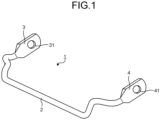
- FIG. 1 is a side view illustrating an example of a configuration of a stabilizer manufactured in an embodiment of the present invention.
- a stabilizer 1 in FIG. 1 is formed of metal or various fiber-reinforced resins (e.g., GFRP).
- the stabilizer 1 includes a main body 2, a first end 3, and a second end 4.
- the main body 2 has both bent ends and a linearly extending central portion.
- the first end 3 is provided at one end of the main body 2.
- the second end 4 is provided at the other end of the main body 2.
- the main body 2 extends in a shape of a column, for example, a circular column. Although an example in which the main body 2 is hollow will be described, the main body 2 may be solid.
- the first end 3 has a flat plate shape.
- a through hole 31 penetrating in a plate thickness direction is formed in the first end 3.
- the second end 4 has a flat plate shape.
- a through hole 41 penetrating in the plate thickness direction is formed in the second end 4.
- the first end 3 is connected to one of suspensions arranged on the right and left sides, and the second end 4 is connected to the other suspension.
- the ends are fixed to the suspensions by fastening members such as bolts being inserted into the through holes.
- FIG. 2 illustrates a manufacturing method in which the stabilizer in FIG. 1 is produced.
- the stabilizer 1 is produced by performing forging on a base material.
- a base material 10 is formed by bending both ends of a cylindrical member, and includes a main body 11, a first end 12, and a second end 13. First, the first end 12 and the second end 13 of the base material 10 are heated (see (a) of FIG. 2 : heating step). In the heating processing, each of the ends is heated by using, for example, a heating coil 110.
- each of the ends is pressed (see (b) of FIG. 2 : flattening step).
- an end (first end 12 in FIG. 2 ) of the base material 10 is held by a holding member 120a, and the end placed on the holding member 120a is pressed by a pressing member 120b, whereby the end is crushed and flattened (see (c) of FIG. 2 ).
- a protrusion 120c is formed on the pressing member 120b at a position corresponding to a through hole formation position of the base material 10. Therefore, a recess 12a having the shape of the protrusion 120c is formed at the end of the base material 10 by the flattening (recess forming step).
- the flattening step and the recess forming step are simultaneously performed.
- cutting processing is performed (see (d) of FIG. 2 ).
- through hole forming processing through hole forming step
- trimming trim (trimming step) are performed on the first end 12 and the second end 13.
- (d) of FIG. 2 illustrates an example of processing the first end 12. The same applies to the second end 13.
- the through hole is formed by perforating the first end 12 by using a perforating member 130a.
- the first end 12 is placed on a support member 130b, and pressed toward the support member 130b by a stripper 130c.
- the support member 130b and the stripper 130c have hollow portions through which a tip of the perforating member 130a can be inserted.
- the perforating member 130a penetrates the stripper 130c, and performs perforation at a through hole formation position of the first end 12 including the recess 12a, whereby the through hole (through hole 12b in (e) of FIG. 2 ) is formed in the first end 12.
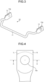
- FIG. 3 illustrates a base material, before forging processing, for producing the stabilizer in FIG. 1 .
- FIG. 4 illustrates a configuration of an end of the base material before forging.
- FIG. 5 is a cross-sectional view taken along line A-A in FIG. 4 .
- the base material 10 in FIGS. 3 and 4 includes the main body 11, the first end 12, and the second end 13.
- the main body 11 has both bent ends.
- the first end 12 is provided at one end of the main body 11.
- the second end 13 is provided at the other end of the main body 11.
- the recess 12a and a recess 13a are formed at the first end 12 and the second end 13, respectively.
- the recess 12a has a hole shape forming conical internal space.
- the recess 12a is set in a region including the through hole formation position.
- a range in which the recess 12a is formed for example, a region having a diameter of a width W 1 of an opening on the surface of the first end 12 are set in accordance with a region where the fastening member is disposed in the first end 12 (first end 3).
- the recess 12a is preferably formed at a position where a central axis of the perforating member 130a passes through the apex of the cone.
- the width W 1 is set in a range of 70% or more and less than 100% of a diameter R 1 of the perforating member 130a (i.e., diameter of through hole 12b). Furthermore, a depth D 1 of the recess is set in a range of 10% or more and 80% or less of a thickness H 1 of the first end 12. A load on the perforating member 130a can be reliably reduced by setting the width W 1 and the diameter R 1 in the above-described range.
- the recess 12a is described as forming conical space, the recess 12a may form another recessed shape such as frustum-shaped space.
- the outer shape of the first end 12 is formed by using a trim blade 130d (see (d) of FIG. 2 ).
- the outer shape of the first end 3 is formed by performing cutting along a processing line L C of the first end 12 by using the trim blade 130d.
- burr removing processing of removing a burr with a molding member 140a is performed (see (e) of FIG. 2 : burr removing step).
- the first end 12 is placed on a support member 140b.
- a burr formed around the through hole 12b is crushed by sandwiching the first end 12 between the molding member 140a and the support member 140b, and the burr is removed. This causes the stabilizer 1 in FIG. 1 to be produced.
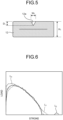
- FIG. 6 illustrates a load change, at the time when a through hole is formed with a perforating member, depending on the presence or absence of a recess.
- FIG. 6 illustrates an example in which a load change at the time when a through hole is formed with a perforating member in a case where the perforating member 130a has the diameter R 1 of 14.4 mm and the base material 10 has an end having the thickness H 1 of 7.3 mm is analyzed.
- a stroke corresponds to an entry length of the perforating member 130a from the surface of the base material.
- a curve L 1 indicates a load change in a case where the recess 12a has the width W 1 of 12.96 mm and the depth D 1 of 5.00 mm.
- a curve L 2 indicates a load change in a case where the recess 12a has the width W 1 of 12.96 mm and the depth D 1 of 3.00 mm.
- a curve L 3 indicates a load change in a case where the recess 12a is not provided. An analysis result in FIG. 6 indicates that the recess 12a reduces a load.
- FIG. 7 illustrates a load change, at the time when a through hole is formed with a perforating member, depending on the presence or absence of a recess in a case where the solid base material is used.
- FIG. 7 illustrates an example in which a load change at the time when a through hole is formed with a perforating member in a case where the perforating member 130a has the diameter R 1 of 14.4 mm and the base material has an end having the thickness of 7.3 mm is analyzed.
- a curve L 11 indicates a load change in a case where the recess (corresponding to recess 12a) has the width W 1 of 12.96 mm and the depth D 1 of 5.00 mm.
- a curve L 12 indicates a load change in a case where the recess is not provided.
- An analysis result in FIG. 7 indicates that the recess reduces a load.
- a recess is formed at a through hole formation position, and a through hole is formed by perforating a region including the recess in the base material for producing the stabilizer.
- a recess reduces a load to be applied to the perforating member 130a, which can improve the durability of the perforating member.
- a load to be applied to the recess at the time of perforation is reduced, which can inhibit warpage of an end generated by a load caused by perforation and a decrease in adhesion between inner peripheral surfaces.
- the present invention should not be limited only by the above-described embodiment.
- the present invention can be applied to a product in which a through hole is formed by perforation or on which trimming is performed.
- the flattening and the formation of the recess may be performed at different timings. That is, although, in the embodiment, the flattening step and the recess forming step are simultaneously performed, the flattening step and the recess forming step may be performed at different timings.
- the present invention may include various embodiments not described here, and various design changes and the like can be made without departing from the technical idea specified by the claims.
- a method of manufacturing a stabilizer according to the present invention and a base material are preferred to improve the durability of a perforating member that forms a through hole by perforation.
Landscapes
- Engineering & Computer Science (AREA)
- Mechanical Engineering (AREA)
- Vehicle Body Suspensions (AREA)
- Forging (AREA)
Abstract
Description
- The present invention relates to a method of manufacturing a stabilizer and a base material.
- A stabilizer used in a vehicle or the like is attached to the vehicle to stabilize the posture of the vehicle. The stabilizer is formed by deforming, for example, a solid or hollow rod-shaped member (e.g., see Patent Literature 1). The stabilizer is connected to the vehicle at both ends thereof. The connection portions have flat shapes. In an end of the stabilizer, a through hole through which a fastening member such as a bolt is to be inserted is formed after the rod-shaped member is crushed and flattened.
- Patent Literature 1:
JP S63-273541 A - A through hole at an end of a stabilizer is formed by perforating the end with a perforating member. In the case, the perforating member is worn by a load applied from a base material to the perforating member at the time of perforation. Improving the durability of the perforating member has been demanded to improve the number of times of use of the perforating member.
- The present invention has been made in view of the above, and an object thereof is to provide a method of manufacturing a stabilizer and a base material capable of improving the durability of a perforating member that forms a through hole by perforation.
- To solve the above-described problem and achieve the object, a method according to the present invention of manufacturing a stabilizer having a through hole at each of both ends by performing forging processing on a base material includes: a recess forming step of forming a recess at a through hole formation position corresponding to the through hole of the stabilizer at an end of the base material; and a through hole forming step of forming a through hole by performing perforation at the through hole formation position including the recess.
- Moreover, in the above-described method of manufacturing a stabilizer according to the present invention, in the recess forming step, the recess is formed while the end of the base material is flattened.
- Moreover, the above-described method of manufacturing a stabilizer according to the present invention further includes a heating step of heating the end of the base material, and in the recess forming step, the recess is formed in the end heated in the heating step.
- Moreover, the above-described method of manufacturing a stabilizer according to the present invention further includes a burr removing step of removing a burr in a region including the through hole formed in the through hole forming step.
- Moreover, a base material according to the present invention for producing a stabilizer having a through hole formed at each of both ends by forging processing includes a recess formed at a through hole formation position corresponding to the through hole of the stabilizer at an end of the base material.
- According to the present invention, an effect of improving the durability of a perforating member that forms a through hole by perforation can be exhibited.
-
-
FIG. 1 is a side view illustrating an example of a configuration of a stabilizer manufactured in an embodiment of the present invention. -
FIG. 2 illustrates a manufacturing method in which the stabilizer inFIG. 1 is produced. -
FIG. 3 illustrates a base material, before forging processing, for producing the stabilizer inFIG. 1 . -
FIG. 4 illustrates a configuration of an end of the base material before forging processing. -
FIG. 5 is a cross-sectional view taken along line A-A inFIG. 4 . -
FIG. 6 illustrates a load change, at the time when a through hole is formed with a perforating member, depending on the presence or absence of a recess. -
FIG. 7 illustrates a load change, at the time when a through hole is formed with a perforating member, depending on the presence or absence of a recess in a case where a solid base material is used. - An embodiment for carrying out the present invention (hereinafter, referred to as "embodiment") will be described below with reference to the accompanying drawings. Note that the drawings are schematic, and the relation between the thickness and the width of each of portions, the ratio between the thicknesses of the portions, and the like may be different from those in reality. Portions having different dimensional relations and ratios may be included in mutual drawings.
-
FIG. 1 is a side view illustrating an example of a configuration of a stabilizer manufactured in an embodiment of the present invention. A stabilizer 1 inFIG. 1 is formed of metal or various fiber-reinforced resins (e.g., GFRP). The stabilizer 1 includes amain body 2, afirst end 3, and asecond end 4. Themain body 2 has both bent ends and a linearly extending central portion. Thefirst end 3 is provided at one end of themain body 2. Thesecond end 4 is provided at the other end of themain body 2. - The
main body 2 extends in a shape of a column, for example, a circular column. Although an example in which themain body 2 is hollow will be described, themain body 2 may be solid. - The
first end 3 has a flat plate shape. A throughhole 31 penetrating in a plate thickness direction is formed in thefirst end 3. - The
second end 4 has a flat plate shape. A through hole 41 penetrating in the plate thickness direction is formed in thesecond end 4. - For example, when the stabilizer 1 is provided in an automobile, the
first end 3 is connected to one of suspensions arranged on the right and left sides, and thesecond end 4 is connected to the other suspension. In the case, the ends are fixed to the suspensions by fastening members such as bolts being inserted into the through holes. - Subsequently, a method of manufacturing the stabilizer 1 will be described with reference to
FIGS. 2 to 5 .FIG. 2 illustrates a manufacturing method in which the stabilizer inFIG. 1 is produced. The stabilizer 1 is produced by performing forging on a base material. - A
base material 10 is formed by bending both ends of a cylindrical member, and includes amain body 11, afirst end 12, and asecond end 13. First, thefirst end 12 and thesecond end 13 of thebase material 10 are heated (see (a) ofFIG. 2 : heating step). In the heating processing, each of the ends is heated by using, for example, aheating coil 110. - After both the ends of the
base material 10 are heated, each of the ends is pressed (see (b) ofFIG. 2 : flattening step). For example, as illustrated in (b) ofFIG. 2 , an end (first end 12 inFIG. 2 ) of thebase material 10 is held by aholding member 120a, and the end placed on theholding member 120a is pressed by apressing member 120b, whereby the end is crushed and flattened (see (c) ofFIG. 2 ). In the case, aprotrusion 120c is formed on the pressingmember 120b at a position corresponding to a through hole formation position of thebase material 10. Therefore, arecess 12a having the shape of theprotrusion 120c is formed at the end of thebase material 10 by the flattening (recess forming step). In the embodiment, the flattening step and the recess forming step are simultaneously performed. - After the
first end 12 and thesecond end 13 are formed, cutting processing is performed (see (d) ofFIG. 2 ). In the cutting processing, through hole forming processing (through hole forming step) and trimming (trimming step) are performed on thefirst end 12 and thesecond end 13. Here, (d) ofFIG. 2 illustrates an example of processing thefirst end 12. The same applies to thesecond end 13. - The through hole is formed by perforating the
first end 12 by using a perforatingmember 130a. In the case, thefirst end 12 is placed on asupport member 130b, and pressed toward thesupport member 130b by astripper 130c. Thesupport member 130b and thestripper 130c have hollow portions through which a tip of the perforatingmember 130a can be inserted. The perforatingmember 130a penetrates thestripper 130c, and performs perforation at a through hole formation position of thefirst end 12 including therecess 12a, whereby the through hole (throughhole 12b in (e) ofFIG. 2 ) is formed in thefirst end 12. -
FIG. 3 illustrates a base material, before forging processing, for producing the stabilizer inFIG. 1 .FIG. 4 illustrates a configuration of an end of the base material before forging.FIG. 5 is a cross-sectional view taken along line A-A inFIG. 4 . Thebase material 10 inFIGS. 3 and 4 includes themain body 11, thefirst end 12, and thesecond end 13. Themain body 11 has both bent ends. Thefirst end 12 is provided at one end of themain body 11. Thesecond end 13 is provided at the other end of themain body 11. Furthermore, therecess 12a and arecess 13a are formed at thefirst end 12 and thesecond end 13, respectively. - For example, the
recess 12a has a hole shape forming conical internal space. Therecess 12a is set in a region including the through hole formation position. A range in which therecess 12a is formed, for example, a region having a diameter of a width W1 of an opening on the surface of thefirst end 12 are set in accordance with a region where the fastening member is disposed in the first end 12 (first end 3). In the case, therecess 12a is preferably formed at a position where a central axis of the perforatingmember 130a passes through the apex of the cone. Furthermore, the width W1 is set in a range of 70% or more and less than 100% of a diameter R1 of the perforatingmember 130a (i.e., diameter of throughhole 12b). Furthermore, a depth D1 of the recess is set in a range of 10% or more and 80% or less of a thickness H1 of thefirst end 12. A load on the perforatingmember 130a can be reliably reduced by setting the width W1 and the diameter R1 in the above-described range. Although, in the embodiment, therecess 12a is described as forming conical space, therecess 12a may form another recessed shape such as frustum-shaped space. - Note that the same applies to the
recess 13a. - Returning to
FIG. 2 , in the trimming, the outer shape of thefirst end 12 is formed by using atrim blade 130d (see (d) ofFIG. 2 ). In the trimming, for example, as illustrated inFIG. 4 , the outer shape of thefirst end 3 is formed by performing cutting along a processing line LC of thefirst end 12 by using thetrim blade 130d. - Note that either through hole formation or trimming may be performed first.
- After the cutting processing, burr removing processing of removing a burr with a
molding member 140a is performed (see (e) ofFIG. 2 : burr removing step). In the case, thefirst end 12 is placed on asupport member 140b. A burr formed around the throughhole 12b is crushed by sandwiching thefirst end 12 between themolding member 140a and thesupport member 140b, and the burr is removed. This causes the stabilizer 1 inFIG. 1 to be produced. - Here, the difference in a load applied to the perforating
member 130a depending on the presence or absence of a recess in a base material will be described with reference toFIG. 6. FIG. 6 illustrates a load change, at the time when a through hole is formed with a perforating member, depending on the presence or absence of a recess.FIG. 6 illustrates an example in which a load change at the time when a through hole is formed with a perforating member in a case where the perforatingmember 130a has the diameter R1 of 14.4 mm and thebase material 10 has an end having the thickness H1 of 7.3 mm is analyzed. A stroke corresponds to an entry length of the perforatingmember 130a from the surface of the base material. A curve L1 indicates a load change in a case where therecess 12a has the width W1 of 12.96 mm and the depth D1 of 5.00 mm. A curve L2 indicates a load change in a case where therecess 12a has the width W1 of 12.96 mm and the depth D1 of 3.00 mm. A curve L3 indicates a load change in a case where therecess 12a is not provided. An analysis result inFIG. 6 indicates that therecess 12a reduces a load. - Furthermore, the difference in a load applied to the perforating
member 130a depending on the presence or absence of a recess in a solid base material will be described with reference toFIG. 7. FIG. 7 illustrates a load change, at the time when a through hole is formed with a perforating member, depending on the presence or absence of a recess in a case where the solid base material is used.FIG. 7 illustrates an example in which a load change at the time when a through hole is formed with a perforating member in a case where the perforatingmember 130a has the diameter R1 of 14.4 mm and the base material has an end having the thickness of 7.3 mm is analyzed. A curve L11 indicates a load change in a case where the recess (corresponding to recess 12a) has the width W1 of 12.96 mm and the depth D1 of 5.00 mm. A curve L12 indicates a load change in a case where the recess is not provided. An analysis result inFIG. 7 indicates that the recess reduces a load. - In the above-described embodiment of the present invention, a recess is formed at a through hole formation position, and a through hole is formed by perforating a region including the recess in the base material for producing the stabilizer. According to the embodiment, a recess reduces a load to be applied to the perforating
member 130a, which can improve the durability of the perforating member. - Furthermore, according to the embodiment, a load to be applied to the recess at the time of perforation is reduced, which can inhibit warpage of an end generated by a load caused by perforation and a decrease in adhesion between inner peripheral surfaces.
- Although the embodiment for carrying out the present invention has been described so far, the present invention should not be limited only by the above-described embodiment. For example, the present invention can be applied to a product in which a through hole is formed by perforation or on which trimming is performed.
Furthermore, although, in the embodiment, an example in which a recess is formed while an end of thebase material 10 is flattened has been described, the flattening and the formation of the recess may be performed at different timings. That is, although, in the embodiment, the flattening step and the recess forming step are simultaneously performed, the flattening step and the recess forming step may be performed at different timings. - As described above, the present invention may include various embodiments not described here, and various design changes and the like can be made without departing from the technical idea specified by the claims.
- As described above, a method of manufacturing a stabilizer according to the present invention and a base material are preferred to improve the durability of a perforating member that forms a through hole by perforation.
-
- 1 STABILIZER
- 2, 11 MAIN BODY
- 3, 12 FIRST END
- 4, 13 SECOND END
- 10 BASE MATERIAL
- 12a, 13a RECESS
- 31, 41 THROUGH HOLE
- 120a HOLDING MEMBER
- 120b PRESSING MEMBER
- 120c PROTRUSION
- 130a PERFORATING MEMBER
- 130b, 140b SUPPORT MEMBER
- 130c STRIPPER
- 130d TRIM BLADE
- 140a MOLDING MEMBER
Claims (5)
- A method of manufacturing a stabilizer having a through hole at each of both ends by performing forging processing on a base material, the method comprising:a recess forming step of forming a recess at a through hole formation position corresponding to the through hole of the stabilizer at an end of the base material; anda through hole forming step of forming a through hole by performing perforation at the through hole formation position including the recess.
- The method of manufacturing a stabilizer according to claim 1, wherein, in the recess forming step, the recess is formed while the end of the base material is flattened.
- The method of manufacturing a stabilizer according to claim 1 or 2, further comprising a heating step of heating the end of the base material,
wherein, in the recess forming step, the recess is formed in the end heated in the heating step. - The method of manufacturing a stabilizer according to claim 1, further comprising
a burr removing step of removing a burr in a region including the through hole formed in the through hole forming step. - A base material for producing a stabilizer having a through hole formed at each of both ends by forging processing, comprising
a recess formed at a through hole formation position corresponding to the through hole of the stabilizer at an end of the base material.
Applications Claiming Priority (2)
| Application Number | Priority Date | Filing Date | Title |
|---|---|---|---|
| JP2022058972A JP2023150072A (en) | 2022-03-31 | 2022-03-31 | Stabilizer manufacturing method and base material |
| PCT/JP2023/010528 WO2023189706A1 (en) | 2022-03-31 | 2023-03-17 | Method for manufacturing stabilizer, and base material |
Publications (2)
| Publication Number | Publication Date |
|---|---|
| EP4501486A1 true EP4501486A1 (en) | 2025-02-05 |
| EP4501486A4 EP4501486A4 (en) | 2025-07-16 |
Family
ID=88201814
Family Applications (1)
| Application Number | Title | Priority Date | Filing Date |
|---|---|---|---|
| EP23779723.8A Pending EP4501486A4 (en) | 2022-03-31 | 2023-03-17 | METHOD FOR PRODUCING A STABILIZER AND BASE MATERIAL |
Country Status (6)
| Country | Link |
|---|---|
| US (1) | US20250205773A1 (en) |
| EP (1) | EP4501486A4 (en) |
| JP (1) | JP2023150072A (en) |
| CN (1) | CN118973734A (en) |
| MX (1) | MX2024011465A (en) |
| WO (1) | WO2023189706A1 (en) |
Family Cites Families (13)
| Publication number | Priority date | Publication date | Assignee | Title |
|---|---|---|---|---|
| US4781054A (en) * | 1986-12-19 | 1988-11-01 | Rockwell International Suspension Systems Company | Apparatus for bending and forming heated tubular workpieces |
| JP3168236B2 (en) * | 1994-02-28 | 2001-05-21 | 日本発条株式会社 | Hollow stabilizer for vehicles and method of manufacturing the same |
| JPH08332529A (en) * | 1995-06-09 | 1996-12-17 | Mitsubishi Motors Corp | Die for piercing hole and piercing hole processing method |
| DE19857589C2 (en) * | 1997-12-15 | 2000-12-28 | Honsel Profilprodukte Gmbh | Impact girders for vehicle doors and processes for their manufacture |
| JP2000158059A (en) * | 1998-11-24 | 2000-06-13 | Mitsui High Tec Inc | Scrap floating prevention die device |
| EP1775042B1 (en) * | 2005-10-14 | 2009-04-01 | Gassner Ges. m.b.H. & Co. KG | Method and apparatus for punching a metal sheet |
| JP2007320408A (en) * | 2006-05-31 | 2007-12-13 | Mitsubishi Steel Mfg Co Ltd | Hollow stabilizer |
| JP6567292B2 (en) * | 2014-03-17 | 2019-08-28 | 株式会社東亜鍛工所 | Method for manufacturing metal plate having holes, method for manufacturing external gear with peripheral hole, and method for manufacturing metal plate |
| JP5961223B2 (en) * | 2014-04-10 | 2016-08-02 | 日本発條株式会社 | Pipe-shaped member and end sealing method thereof |
| JP5923154B2 (en) * | 2014-10-28 | 2016-05-24 | 日本発條株式会社 | Link arm member |
| ES2842185T3 (en) * | 2015-10-20 | 2021-07-13 | Nhk Spring Co Ltd | Vehicle stabilizer |
| JP7154043B2 (en) * | 2018-06-12 | 2022-10-17 | 日本発條株式会社 | stabilizer |
| JP7463139B2 (en) * | 2020-03-11 | 2024-04-08 | 株式会社エイチワン | Metal processing device and metal processing method |
-
2022
- 2022-03-31 JP JP2022058972A patent/JP2023150072A/en active Pending
-
2023
- 2023-03-17 EP EP23779723.8A patent/EP4501486A4/en active Pending
- 2023-03-17 US US18/850,973 patent/US20250205773A1/en active Pending
- 2023-03-17 CN CN202380029725.0A patent/CN118973734A/en active Pending
- 2023-03-17 WO PCT/JP2023/010528 patent/WO2023189706A1/en not_active Ceased
- 2023-03-17 MX MX2024011465A patent/MX2024011465A/en unknown
Also Published As
| Publication number | Publication date |
|---|---|
| US20250205773A1 (en) | 2025-06-26 |
| WO2023189706A1 (en) | 2023-10-05 |
| JP2023150072A (en) | 2023-10-16 |
| MX2024011465A (en) | 2024-09-25 |
| EP4501486A4 (en) | 2025-07-16 |
| CN118973734A (en) | 2024-11-15 |
Similar Documents
| Publication | Publication Date | Title |
|---|---|---|
| US20220226879A1 (en) | Method and a Device for the Manufacturing of Washers for Locking and Washer for Locking | |
| CN107405665B (en) | Inner edge flanging processing method | |
| KR20090023718A (en) | Punch rivet and die | |
| US8752850B2 (en) | Arm component for vehicles and its manufacturing method | |
| US8852752B2 (en) | Flow formed drum with a retention ring and a substantially burr free tooth profile | |
| US20190291160A1 (en) | Method for machining a sheet-metal profile | |
| JP2010075931A (en) | Method of press-forming cylindrical metallic part having flange | |
| CN113365752B (en) | Method for manufacturing stamped member and method for manufacturing blank | |
| EP1477250B1 (en) | Method of making self-piercing nuts | |
| US20250205773A1 (en) | Method of manufacturing stabilizer and base material | |
| JP2012171587A (en) | Belt mounting tool and method of manufacturing the same | |
| CN104668434B (en) | The method for manufacturing installation unit | |
| US11192162B2 (en) | Method and device for forming a semi-finished product | |
| US20030087705A1 (en) | Forging method of a hollow part | |
| JP7778023B2 (en) | Stabilizer manufacturing method and base material | |
| EP3162674B1 (en) | Crawler track shoe core metal, resilient crawler track shoe, and crawler track shoe core metal manufacturing method | |
| US20150352627A1 (en) | Cold formed product and method for making | |
| KR101605422B1 (en) | Lock Nut Manufacturing Method by Forging and Lock Nut Thereof | |
| JP2007075869A (en) | Burring method | |
| US10010929B2 (en) | Apparatus to produce self-piercing and clinch nut and method of producing self-piercing and clinch nut | |
| JP3492746B2 (en) | Patterned tool base | |
| US10543728B2 (en) | End plate of suspension member | |
| KR101480440B1 (en) | Making method of pan nut | |
| JPH0252126A (en) | Manufacture of grooved cylindrical part | |
| KR102202026B1 (en) | Manufacturing method of parts for door lock device in which die roll phenomenon is suppressed |
Legal Events
| Date | Code | Title | Description |
|---|---|---|---|
| STAA | Information on the status of an ep patent application or granted ep patent |
Free format text: STATUS: THE INTERNATIONAL PUBLICATION HAS BEEN MADE |
|
| PUAI | Public reference made under article 153(3) epc to a published international application that has entered the european phase |
Free format text: ORIGINAL CODE: 0009012 |
|
| STAA | Information on the status of an ep patent application or granted ep patent |
Free format text: STATUS: REQUEST FOR EXAMINATION WAS MADE |
|
| 17P | Request for examination filed |
Effective date: 20240925 |
|
| AK | Designated contracting states |
Kind code of ref document: A1 Designated state(s): AL AT BE BG CH CY CZ DE DK EE ES FI FR GB GR HR HU IE IS IT LI LT LU LV MC ME MK MT NL NO PL PT RO RS SE SI SK SM TR |
|
| DAV | Request for validation of the european patent (deleted) | ||
| DAX | Request for extension of the european patent (deleted) | ||
| A4 | Supplementary search report drawn up and despatched |
Effective date: 20250616 |
|
| RIC1 | Information provided on ipc code assigned before grant |
Ipc: B21K 21/12 20060101AFI20250610BHEP Ipc: B21J 5/10 20060101ALI20250610BHEP Ipc: B21J 9/04 20060101ALI20250610BHEP Ipc: B60G 21/055 20060101ALI20250610BHEP Ipc: B21D 28/16 20060101ALI20250610BHEP Ipc: B21D 28/24 20060101ALI20250610BHEP Ipc: B21D 28/26 20060101ALI20250610BHEP Ipc: B21D 28/28 20060101ALI20250610BHEP Ipc: B21D 41/04 20060101ALI20250610BHEP Ipc: B21K 21/14 20060101ALI20250610BHEP Ipc: B21K 23/00 20060101ALI20250610BHEP |
|
| STAA | Information on the status of an ep patent application or granted ep patent |
Free format text: STATUS: EXAMINATION IS IN PROGRESS |