EP4501473A1 - Transducer including piezoelectric element and method of producing same - Google Patents
Transducer including piezoelectric element and method of producing same Download PDFInfo
- Publication number
- EP4501473A1 EP4501473A1 EP24190668.4A EP24190668A EP4501473A1 EP 4501473 A1 EP4501473 A1 EP 4501473A1 EP 24190668 A EP24190668 A EP 24190668A EP 4501473 A1 EP4501473 A1 EP 4501473A1
- Authority
- EP
- European Patent Office
- Prior art keywords
- flexible substrate
- holes
- support member
- piezoelectric
- transducer
- Prior art date
- Legal status (The legal status is an assumption and is not a legal conclusion. Google has not performed a legal analysis and makes no representation as to the accuracy of the status listed.)
- Granted
Links
Images


Classifications
-
- B—PERFORMING OPERATIONS; TRANSPORTING
- B06—GENERATING OR TRANSMITTING MECHANICAL VIBRATIONS IN GENERAL
- B06B—METHODS OR APPARATUS FOR GENERATING OR TRANSMITTING MECHANICAL VIBRATIONS OF INFRASONIC, SONIC, OR ULTRASONIC FREQUENCY, e.g. FOR PERFORMING MECHANICAL WORK IN GENERAL
- B06B1/00—Methods or apparatus for generating mechanical vibrations of infrasonic, sonic, or ultrasonic frequency
- B06B1/02—Methods or apparatus for generating mechanical vibrations of infrasonic, sonic, or ultrasonic frequency making use of electrical energy
- B06B1/06—Methods or apparatus for generating mechanical vibrations of infrasonic, sonic, or ultrasonic frequency making use of electrical energy operating with piezoelectric effect or with electrostriction
- B06B1/0644—Methods or apparatus for generating mechanical vibrations of infrasonic, sonic, or ultrasonic frequency making use of electrical energy operating with piezoelectric effect or with electrostriction using a single piezoelectric element
-
- H—ELECTRICITY
- H04—ELECTRIC COMMUNICATION TECHNIQUE
- H04R—LOUDSPEAKERS, MICROPHONES, GRAMOPHONE PICK-UPS OR LIKE ACOUSTIC ELECTROMECHANICAL TRANSDUCERS; ELECTRIC HEARING AIDS; PUBLIC ADDRESS SYSTEMS
- H04R7/00—Diaphragms for electromechanical transducers; Cones
- H04R7/02—Diaphragms for electromechanical transducers; Cones characterised by the construction
- H04R7/04—Plane diaphragms
-
- H—ELECTRICITY
- H04—ELECTRIC COMMUNICATION TECHNIQUE
- H04R—LOUDSPEAKERS, MICROPHONES, GRAMOPHONE PICK-UPS OR LIKE ACOUSTIC ELECTROMECHANICAL TRANSDUCERS; ELECTRIC HEARING AIDS; PUBLIC ADDRESS SYSTEMS
- H04R17/00—Piezoelectric transducers; Electrostrictive transducers
-
- B—PERFORMING OPERATIONS; TRANSPORTING
- B06—GENERATING OR TRANSMITTING MECHANICAL VIBRATIONS IN GENERAL
- B06B—METHODS OR APPARATUS FOR GENERATING OR TRANSMITTING MECHANICAL VIBRATIONS OF INFRASONIC, SONIC, OR ULTRASONIC FREQUENCY, e.g. FOR PERFORMING MECHANICAL WORK IN GENERAL
- B06B1/00—Methods or apparatus for generating mechanical vibrations of infrasonic, sonic, or ultrasonic frequency
- B06B1/02—Methods or apparatus for generating mechanical vibrations of infrasonic, sonic, or ultrasonic frequency making use of electrical energy
- B06B1/06—Methods or apparatus for generating mechanical vibrations of infrasonic, sonic, or ultrasonic frequency making use of electrical energy operating with piezoelectric effect or with electrostriction
- B06B1/0688—Methods or apparatus for generating mechanical vibrations of infrasonic, sonic, or ultrasonic frequency making use of electrical energy operating with piezoelectric effect or with electrostriction with foil-type piezoelectric elements, e.g. PVDF
-
- H—ELECTRICITY
- H04—ELECTRIC COMMUNICATION TECHNIQUE
- H04R—LOUDSPEAKERS, MICROPHONES, GRAMOPHONE PICK-UPS OR LIKE ACOUSTIC ELECTROMECHANICAL TRANSDUCERS; ELECTRIC HEARING AIDS; PUBLIC ADDRESS SYSTEMS
- H04R31/00—Apparatus or processes specially adapted for the manufacture of transducers or diaphragms therefor
- H04R31/003—Apparatus or processes specially adapted for the manufacture of transducers or diaphragms therefor for diaphragms or their outer suspension
-
- H—ELECTRICITY
- H04—ELECTRIC COMMUNICATION TECHNIQUE
- H04R—LOUDSPEAKERS, MICROPHONES, GRAMOPHONE PICK-UPS OR LIKE ACOUSTIC ELECTROMECHANICAL TRANSDUCERS; ELECTRIC HEARING AIDS; PUBLIC ADDRESS SYSTEMS
- H04R7/00—Diaphragms for electromechanical transducers; Cones
- H04R7/16—Mounting or tensioning of diaphragms or cones
-
- H—ELECTRICITY
- H10—SEMICONDUCTOR DEVICES; ELECTRIC SOLID-STATE DEVICES NOT OTHERWISE PROVIDED FOR
- H10N—ELECTRIC SOLID-STATE DEVICES NOT OTHERWISE PROVIDED FOR
- H10N30/00—Piezoelectric or electrostrictive devices
- H10N30/20—Piezoelectric or electrostrictive devices with electrical input and mechanical output, e.g. functioning as actuators or vibrators
- H10N30/204—Piezoelectric or electrostrictive devices with electrical input and mechanical output, e.g. functioning as actuators or vibrators using bending displacement, e.g. unimorph, bimorph or multimorph cantilever or membrane benders
- H10N30/2047—Membrane type
-
- H—ELECTRICITY
- H10—SEMICONDUCTOR DEVICES; ELECTRIC SOLID-STATE DEVICES NOT OTHERWISE PROVIDED FOR
- H10N—ELECTRIC SOLID-STATE DEVICES NOT OTHERWISE PROVIDED FOR
- H10N30/00—Piezoelectric or electrostrictive devices
- H10N30/20—Piezoelectric or electrostrictive devices with electrical input and mechanical output, e.g. functioning as actuators or vibrators
- H10N30/204—Piezoelectric or electrostrictive devices with electrical input and mechanical output, e.g. functioning as actuators or vibrators using bending displacement, e.g. unimorph, bimorph or multimorph cantilever or membrane benders
- H10N30/2047—Membrane type
- H10N30/2048—Membrane type having non-planar shape
Definitions
- the present disclosure relates to a transducer using a piezoelectric element, which can be used as a speaker, a sensor, or the like.
- WO 2020/202351A discloses an invention related to an ultrasonic transducer.
- the disclosed ultrasonic transducer includes an elastic plate having elasticity that allows the elastic plate to vibrate in a thickness direction of the elastic plate.
- the elastic plate is formed of stainless steel, a Ni-Fe alloy, an aluminum alloy, a titanium alloy, a carbon fiber-reinforced plastic, ceramic, or the like. Piezoelectric elements are fixed to a first surface of the elastic plate in a state in which the piezoelectric elements are aligned in parallel in a planar direction of the elastic plate.
- Each piezoelectric element includes a piezoelectric body formed of PZT, a pair of an upper electrode layer and a lower electrode layer disposed on both sides of the piezoelectric body in a thickness direction of the piezoelectric body. Moreover, the piezoelectric element includes a sealing member having tubes that respectively surrounds the piezoelectric elements in a plan view, and a flexible wiring board serving as a voltage supply channel for the piezoelectric elements.
- the elastic plate has vibration regions, low-rigidity regions, and constraining regions.
- the piezoelectric elements are respectively mounted on the vibration regions.
- the low-rigidity regions respectively surround the vibration regions.
- the constraining regions respectively surround the low-rigidity regions.
- a slit is formed in a boundary region of the elastic plate, where the boundary region is positioned outward of the constraining region in a diameter direction. Since the piezoelectric elements are respectively disposed on the vibration regions respectively surrounded by the low-rigidity regions, the multiple vibration regions can be disposed in close proximity to each other.
- the vibration regions are disposed on the first surface of the elastic plate in close proximity to each other.
- the piezoelectric elements are individually fixed to corresponding vibration regions.
- a flexible wiring board is disposed on the surface of the elastic plate, and the flexible wiring board needs to be individually wired to each of the piezoelectric elements. Therefore, a production process becomes very complicated.
- the present disclosure aims to provide a transducer using piezoelectric element, in which a plurality of vibration portions can be formed using a piezoelectric element without individually providing a large number of piezoelectric elements, and a method of producing such transducer.
- the present disclosure relates to a transducer and method of producing a transducer according to the appended claims. Embodiments are disclosed in the dependent claims.
- a transducer includes a flexible substrate, a piezoelectric element formed on a surface of the flexible substrate, and a support member, in which holes are formed, having a higher rigidity than the flexible substrate.
- the surface of the flexible substrate has an element region in which the piezoelectric element is continuous in a planar direction of the piezoelectric element.
- the support member is stacked to the flexible substrate in a manner such that the holes face the element region.
- the flexible substrate is freely movable in each of the holes, and a region of the flexible substrate corresponding to a region other than the holes of the support member is fixed to the support member.
- inner diameters of the holes facing the element region are preferably identical.
- the transducer including the piezoelectric element of the present disclosure further includes another support member to include two support members.
- the two support members are stacked to both surfaces of the flexible substrate, respectively, in a state in which a center of each of the holes of one of the two support members matches with a center of each of the holes of the other support member, and a region of each of the two support members where the holes are not formed is fixed to the corresponding surface of the flexible substrate.
- the transducer including the piezoelectric element of the present disclosure may be configured such that the support member stacked to the element region is curved.
- an aspect of the present disclosure is directed to a method of producing a transducer, which includes: forming an element region, in which a piezoelectric element is continuous in a planar direction, on a surface of a flexible substrate; forming a support member, in which holes are formed, using a material having a rigidity higher than the flexible substrate; and stacking the flexible substrate to the support member in a manner such that the holes face the element region, allowing the flexible substrate to move freely in the holes, and fixing a region of the flexible substrate, which corresponds to a region other than the holes of the support member, to the support member, to produce the transducer including the flexible substrate, and the piezoelectric element formed on the surface of the flexible substrate.
- the forming of the element region includes stacking a lower electrode layer, a piezoelectric material layer, and an upper electrode layer on the surface of the flexible substrate in this order.
- the forming of the element region includes disposing a lower electrode layer on a lower surface of a piezoelectric material layer including a polymer piezoelectric material, and disposing an upper electrode layer on an upper surface of the piezoelectric material layer to form the piezoelectric element, and fixing the piezoelectric element to the surface of the flexible substrate.
- the method of producing the transducer of the present disclosure may further include curving the support member before or after stacking of the flexible substrate to the support member.
- the element region, in which the piezoelectric element is continuous in the planar direction, is formed on the surface of the flexible substrate, the support member having the holes is stacked to the surface of the flexible substrate, the regions of the element region facing the holes function as vibration portions. Since substantially separated multiple vibration portions can be formed with one element region, it is not necessary to form a plurality of small piezoelectric elements. Moreover, it is not necessary to individually wire the vibration portions to a wiring member. Accordingly, a transducer having multiple vibration portions can be formed at low cost.
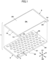
- a transducer 1 of a first embodiment of the present disclosure is illustrated in Figs. 1 and 2 .
- the transducer 1 includes a piezoelectric sheet 2 and a support member 3, which are stacked together.
- the piezoelectric sheet 2 includes a flexible substrate 10.
- the flexible substrate 10 is an organic resin film having an elasticity and being deflection-deformable, such as a polyimide film or the like.
- the flexible substrate 10 has a first surface 11 facing the Z1 direction and a second surface 12 facing the Z2 direction.
- the piezoelectric element 20 is fixed on the first surface 11. As illustrated in Fig.
- the flexible substrate 10 has a square shape in a plan view, and the piezoelectric element 20 fixed to the first surface 11 has also a square shape.
- the piezoelectric element 20 is formed to be continuous in a planar direction over a large area on the first surface 11 of the flexible substrate 10.
- the piezoelectric element 20 includes a lower electrode layer 21 fixed to the first surface 11 of the flexible substrate 10, a piezoelectric material layer 23 stacked on a surface of the lower electrode layer 21, and an upper electrode layer 22 stacked on a surface of the piezoelectric material layer 23.
- a method of producing the piezoelectric element 20 includes formation of a conductive metal layer, such as a copper layer, a silver layer, a gold layer, or the like, on the first surface 11 of the flexible substrate 10 by a method, such as vapor deposition, sputtering, or the like, to produce the lower electrode layer 21.
- a ferroelectric ceramic such as barium titanate, zirconate, lead zirconate titanate, or the like, is fired to form the piezoelectric material layer 23.
- the upper electrode layer 22 is formed by a method, such as vapor deposition, sputtering, or the like.
- the piezoelectric material layer 23 is subjected to a polarization treatment in which an electric field is applied to polarize the piezoelectric material layer 23 in a thickness direction (Z direction).
- the piezoelectric material layer 23 may be formed of a piezoelectric polymer material, such as polyvinylidene fluoride, the lower electrode layer 21 and the upper electrode layer 22 may be stacked onto the film-like piezoelectric material layer 23 to form the piezoelectric element 20, and the piezoelectric element 20 may be bonded to the first surface 11 of the flexible substrate 10.
- a polarization treatment is also performed on the piezoelectric material layer 23 produced in the above manner by applying an electric field to the piezoelectric material layer 23 to polarize in the film thickness direction (Z direction).
- extensions 13 and 14 are formed at the flexible substrate 10.
- a lower surface terminal 24 is formed on the first surface of the extension 13, and an upper surface terminal 25 is formed on the first surface of the extension 14.
- the lower surface terminal 24 is a conductive metal layer.
- the lower surface terminal 24 is formed to be continuous with the lower electrode layer 21 as a single body to thereby connect with the lower electrode layer 21, or is formed as a separate body and is connected to the lower electrode layer 21.
- the upper surface terminal 25 is also a conductive metal layer.
- the upper surface terminal 25 is formed to be continuous with the upper electrode layer 22 as a single body to thereby connect to the upper electrode layer 22, or is formed as a separate body and is connected to the upper electrode layer 22.
- the support member 3 illustrated in Figs. 1 and 2 includes a support plate 30.
- the support plate 30 has a higher rigidity than the flexible substrate 10, and is sufficiently thicker than the flexible substrate 10.
- the support plate 30 is a metal plate, such as a stainless steel plate, or a synthetic resin plate, such as an epoxy-based resin plate.
- the support plate 30 has a first surface 31 facing the Z1 side and a second surface 32 facing the Z2 side that is in an opposite direction to the Z1 side.
- the piezoelectric sheet 2 is stacked on the first surface 31. Holes 35 are formed in the support plate 30. A center line of each hole 35 is vertical to the first surface 31 and the second surface 32, and each hole 35 is formed through the support plate 30.
- the holes 35 are aligned at a constant pitch in a first direction (X direction along the first surface 31, and are also aligned at a constant pitch in a second direction (Y direction) orthogonal to the first direction.
- Each hole 35 is a cylindrical hole having a constant inner diameter from the first surface 31 to the second surface 32 of the support plate 30. All of the holes 35 have the identical inner diameter (inner hole size). Moreover, each hole 35 may have a tapered shape where an inner diameter gradually increases from the first surface 31 fixed on the piezoelectric sheet 2 to the second surface 32 that is an opposite side of the first surface 31. In this case, all of the holes 35 have the identical opening diameter at the first surface 31.
- the piezoelectric sheet 2 is bonded to and fixed on the first surface 31 of the support plate 30 constituting the first support member 3 to thereby form the transducer 1.
- the element region DA of the piezoelectric sheet 2 is continuously present in a predetermined area along the sheet surface.
- the support plate 30 and the piezoelectric sheet 2 are bonded and fixed together in a manner such that the holes 35 face the element region DA.
- the element region DA of the piezoelectric sheet 2 is bonded to and fixed on the first surface 31 of the support plate 30.
- the regions of the element region DA of the piezoelectric sheet 2 facing the holes 35 of the support member 3 are not fixed to the first surface 31 of the support plate 30, and are in a freely movable state.
- the flexible substrate 10 and the piezoelectric element 20 are in a freely movable state inside each hole 35.
- Portions of the element region DA of the piezoelectric sheet 2 facing the regions where the holes 35 are formed function as vibration portions (v).
- the regions where the holes 35 are not formed constitute constraining portions (s) in which the piezoelectric sheet 2 is fixed on the first surface 31 of the support plate 30.
- all of the vibration portions (v) have a circular shape and have the identical diameter.
- the entire surface of the element region DA corresponding to the region between the adjacent holes 35 is fixed on and restrained by the first surface 31 of the support plate 30 so that the movement of the flexible substrate 10 and the piezoelectric element 20 is restricted.
- the piezoelectric sheet 2 is freely movable within the holes 35 in the vibration portions (v), the piezoelectric sheet 2 is curved and deformed to vibrate as indicated with a dashed line in Fig. 2 due to a difference in a volume change between the strained piezoelectric element 20 and the flexible substrate 10. Since the element region DA is fixed on the first surface 31 of the support plate 30 in the constraining portions (s), the piezoelectric sheet 2 is not curved in the thickness direction.
- the transducer 1 When the transducer 1 is used as a piezoelectric speaker, pressure waves are generated from the vibration portions (v) due to flexural vibrations of the piezoelectric sheet 2.
- the piezoelectric sheet 2 positioned inside the hole 35 has a certain resonance frequency according to a mass and elastic modulus of the piezoelectric sheet 2. Therefore, the piezoelectric sheet 2 can be vibrated with high sensitivity by applying an AC voltage of a specific frequency band including the resonance frequency to the piezoelectric sheet 2.
- outputs of the pressure waves may be low with only one vibration portion (v), the multiple vibration portions (v) having the same diameter and the same resonance frequency vibrate in synchronization with each other so that the pressure waves can be generated at a high output as the entire transducer 1.
- the transducer 1 is used as a parametric speaker constituting a highly directional acoustic system.
- This speaker performs FM modulation or AM modulation on, for example, ultrasonic waves of 40 kHz, and reproduces sound in an audible range in a space where two ultrasonic waves intersect, or causes audible sound to appear due to a nonlinear characteristic when ultrasonic waves propagate through the air.
- the transducer 1 of the present embodiment can emit ultrasonic waves synchronized with each other from the multiple vibration portions (v), the output of ultrasonic waves can be increased, and audible sound can be reproduced at a relatively high output.
- the Z1 side where the piezoelectric sheet 2 is disposed may be used as a sound emitting direction (pressure-wave transmitting direction), or the Z2 side where the support member 3 is disposed may be used as a sound emitting direction.
- the directivity of pressure waves can be further enhanced by forming each hole 35 as a long cylindrical hole extending in the Z direction.
- a shape of each hole 35 may be a tapered shape in which an inner diameter is gradually increased toward the Z2 side.
- a piezoelectric sheet 102 which is a modified example, is used in a transducer 1A illustrated in Fig. 5 .
- the piezoelectric sheet 102 is stacked and fixed onto the first surface 31 of the support plate 30 constituting the support member 3.
- a piezoelectric element 20A is stacked on the first surface 11 of the flexible substrate 10
- a piezoelectric element 20B is stacked on the second surface 12 of the flexible substrate 10.
- Each of the piezoelectric element 20A and the piezoelectric element 20B has a configuration in which the piezoelectric material layer 23 is interposed between the lower electrode layer 21 and the upper electrode layer 22.
- the piezoelectric sheet 102 can be vibrated with high sensitivity within the vibration portions (v).
- a transducer 101 of a second embodiment of the present disclosure illustrated in Fig. 3 includes the piezoelectric sheet 2 illustrated in Fig. 4 or the piezoelectric sheet 102 illustrated in Fig. 5 interposed between a support member 3A and a support member 3B.
- Holes 35 formed in the support plate 30 of the support member 3A and holes 35 formed in the support plate 30 of the support member 3B have the identical inner diameter.
- the support members 3A and 3B are positioned so that centers of the holes 35 of the support member 3A match with corresponding centers of the holes 35 of the support member 3B in the Z direction.
- the element region DA of the piezoelectric sheet 2 is bonded to and fixed on both the support member 3A and the support member 3B in the constraining portions (s). Since the transducer 101 can fix and restrain the element region DA with two support members 3A and 3B, generation of a strain in the thickness direction of the piezoelectric material layer 23 can be suppressed in the constraining portions (s) so that an adverse effect of the strain to vibrations of the piezoelectric sheet 2 in the vibration portions (v) can be minimized.
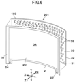
- a transducer 201 of a third embodiment of the present disclosure is illustrated in Figs. 6 and 7 .
- a support member 103 has a curved support plate 30 in which holes 35 are formed.
- the support plate 30 is curved so that the first surface 31 constitutes part of a cylindrical surface.
- the support plate 30 is two-dimensionally curved so that a radius from an imaginary center line extending in the Y direction in parallel with the first surface 31 is constant.
- the piezoelectric sheet 2 is stacked and fixed onto the first surface 31 that is a concaved surface side of the support plate 30.
- the support plate 30 is formed by pressing a metal plate in which holes 35 are formed in advance to curve the metal plate.
- the support plate 30 may be formed by molding a synthetic resin material into a curved shape.
- the piezoelectric sheet 2 is bonded to the concaved surface side of the support plate 30 to follow the concaved surface.
- the piezoelectric sheet 2 and the support member 3 are positioned and bonded so that the holes 35 are positioned within the element region DA of the piezoelectric sheet 2.
- the Z1 side which is the concaved surface side of the support member 3, is used as a sound emitting direction (pressure-wave transmitting direction).
- pressure waves are emitted from the vibration portions (v). Since the vibration portions (v) are aligned along a concaved surface, the pressure waves can be easily concentrated at a predetermined position in the Z1 direction. In a case where the piezoelectric sheet 2 matches with part of a cylindrical surface, the pressure waves are concentrated at around a center line of curvature of the cylindrical surface.
- the transducer 201 is used as a parametric speaker, audibility at an audible spot can be enhanced.
- the piezoelectric sheet 2 may be interposed between two curved support members 103.
- the curvature of the support member 103 is constant in the X direction, but the support member 103 may have a curvature that varies in the X direction depending on the locations, so as to form, for example, a quadratic function curve.
- the support member 103 may have a three dimensionally curved shape having a curvature in both X direction and the Y direction.
- the piezoelectric element 20 (or 20A or 20B), which is continuously formed along a sheet surface, is formed on the piezoelectric sheet 2 (or 102), and multiple vibration portions (V) are formed in the single element region DA where the piezoelectric element 20 is formed. Therefore, a formation process of the piezoelectric element 20 is simple compared to formation process for a structure where a plurality of piezoelectric elements are independently aligned on a surface of substrate. Moreover, it is not necessary to individually provide a wiring channel to each of the vibration portions (v), and a wiring structure can be unified. Therefore, a production process is simple, and production can be performed at low cost.
- a size of the piezoelectric element 20 contributing to vibrations of each vibration portion (v) is determined by an inner diameter of each hole 35.
- the transducer of each of the above embodiments may be also used as a piezoelectric sensor or an ultrasonic sensor.
- ultrasonic waves of approximately 40 kHz are applied to the transducer, the pressure waves thereof cause the piezoelectric element 20 to generate a strain within each vibration portion (v).
- the ultrasonic waves can be detected.
- the holes 35 having the identical inner diameter face the element region DA of the piezoelectric element 20 that is continuous in the planar direction so that the vibration portions (v) having the same resonance frequency are formed.
- first holes having the same inner diameter and second holes having the same inner diameter may be formed in a vibration plate, and the first holes and the second holes may face the same element region DA.
- first vibration portions respectively facing the first holes and second vibration portions respectively facing the second holes can be formed within the same element region DA.
- each first vibration portion and each second vibration portion have mutually different resonance frequencies
- ultrasonic waves having different frequencies can be generated simultaneously or alternately from the first vibrating portions and the second vibrating portions by applying a driving voltage corresponding to the resonance frequency of the first holes and/or the second holes.
- the number of types of holes may be three or more.
Landscapes
- Engineering & Computer Science (AREA)
- Physics & Mathematics (AREA)
- Acoustics & Sound (AREA)
- Signal Processing (AREA)
- Multimedia (AREA)
- Mechanical Engineering (AREA)
- Manufacturing & Machinery (AREA)
- Transducers For Ultrasonic Waves (AREA)
- Piezo-Electric Transducers For Audible Bands (AREA)
- Diaphragms For Electromechanical Transducers (AREA)
- Obtaining Desirable Characteristics In Audible-Bandwidth Transducers (AREA)
Abstract
Description
- The present disclosure relates to a transducer using a piezoelectric element, which can be used as a speaker, a sensor, or the like.
-
WO 2020/202351A discloses an invention related to an ultrasonic transducer. The disclosed ultrasonic transducer includes an elastic plate having elasticity that allows the elastic plate to vibrate in a thickness direction of the elastic plate. The elastic plate is formed of stainless steel, a Ni-Fe alloy, an aluminum alloy, a titanium alloy, a carbon fiber-reinforced plastic, ceramic, or the like. Piezoelectric elements are fixed to a first surface of the elastic plate in a state in which the piezoelectric elements are aligned in parallel in a planar direction of the elastic plate. Each piezoelectric element includes a piezoelectric body formed of PZT, a pair of an upper electrode layer and a lower electrode layer disposed on both sides of the piezoelectric body in a thickness direction of the piezoelectric body. Moreover, the piezoelectric element includes a sealing member having tubes that respectively surrounds the piezoelectric elements in a plan view, and a flexible wiring board serving as a voltage supply channel for the piezoelectric elements. - The elastic plate has vibration regions, low-rigidity regions, and constraining regions. The piezoelectric elements are respectively mounted on the vibration regions. The low-rigidity regions respectively surround the vibration regions. The constraining regions respectively surround the low-rigidity regions. A slit is formed in a boundary region of the elastic plate, where the boundary region is positioned outward of the constraining region in a diameter direction. Since the piezoelectric elements are respectively disposed on the vibration regions respectively surrounded by the low-rigidity regions, the multiple vibration regions can be disposed in close proximity to each other.
- In the ultrasonic transducer disclosed in International Publication No.
WO 2020/202351 , the vibration regions are disposed on the first surface of the elastic plate in close proximity to each other. However, the piezoelectric elements are individually fixed to corresponding vibration regions. Moreover, a flexible wiring board is disposed on the surface of the elastic plate, and the flexible wiring board needs to be individually wired to each of the piezoelectric elements. Therefore, a production process becomes very complicated. - The present disclosure aims to provide a transducer using piezoelectric element, in which a plurality of vibration portions can be formed using a piezoelectric element without individually providing a large number of piezoelectric elements, and a method of producing such transducer.
- The present disclosure relates to a transducer and method of producing a transducer according to the appended claims. Embodiments are disclosed in the dependent claims.
- According to one aspect of the present disclosure, a transducer includes a flexible substrate, a piezoelectric element formed on a surface of the flexible substrate, and a support member, in which holes are formed, having a higher rigidity than the flexible substrate. The surface of the flexible substrate has an element region in which the piezoelectric element is continuous in a planar direction of the piezoelectric element. The support member is stacked to the flexible substrate in a manner such that the holes face the element region. The flexible substrate is freely movable in each of the holes, and a region of the flexible substrate corresponding to a region other than the holes of the support member is fixed to the support member.
- Other objects and further features of the present disclosure will be apparent from the following detailed description when read in conjunction with the accompanying drawings, in which:
-
Fig. 1 is an exploded perspective view illustrating a transducer including a piezoelectric element of a first embodiment of the present disclosure; -
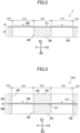
Fig. 2 is a partial cross-sectional view taken along the line II-II, illustrating a state where the transducer illustrated inFig. 1 is assembled; -
Fig. 3 is a partial cross-sectional view illustrating the transducer including the piezoelectric element of a second embodiment of the present disclosure; -
Fig. 4 is an enlarged cross-sectional view illustrating a detailed configuration of a piezoelectric sheet used in the transducer illustrated inFig. 2 ; -
Fig. 5 is an enlarged cross-sectional view illustrating a modified example of the configuration of the piezoelectric sheet used in the transducer illustrated inFig. 2 ; -
Fig. 6 is an exploded perspective view illustrating the transducer including the piezoelectric element of a third embodiment of the present disclosure; and -
Fig. 7 is a perspective view illustrating a state where the transducer of the third embodiment is assembled. - In the transducer including the piezoelectric element of the present disclosure, inner diameters of the holes facing the element region are preferably identical.
- According to an embodiment, the transducer including the piezoelectric element of the present disclosure further includes another support member to include two support members. The two support members are stacked to both surfaces of the flexible substrate, respectively, in a state in which a center of each of the holes of one of the two support members matches with a center of each of the holes of the other support member, and a region of each of the two support members where the holes are not formed is fixed to the corresponding surface of the flexible substrate.
- The transducer including the piezoelectric element of the present disclosure may be configured such that the support member stacked to the element region is curved.
- Moreover, an aspect of the present disclosure is directed to a method of producing a transducer, which includes: forming an element region, in which a piezoelectric element is continuous in a planar direction, on a surface of a flexible substrate; forming a support member, in which holes are formed, using a material having a rigidity higher than the flexible substrate; and stacking the flexible substrate to the support member in a manner such that the holes face the element region, allowing the flexible substrate to move freely in the holes, and fixing a region of the flexible substrate, which corresponds to a region other than the holes of the support member, to the support member, to produce the transducer including the flexible substrate, and the piezoelectric element formed on the surface of the flexible substrate.
- In the method of producing the transducer of the present disclosure, according to an embodiment the forming of the element region includes stacking a lower electrode layer, a piezoelectric material layer, and an upper electrode layer on the surface of the flexible substrate in this order.
- In an embodiment of the method of producing the transducer of the present disclosure, the forming of the element region includes disposing a lower electrode layer on a lower surface of a piezoelectric material layer including a polymer piezoelectric material, and disposing an upper electrode layer on an upper surface of the piezoelectric material layer to form the piezoelectric element, and fixing the piezoelectric element to the surface of the flexible substrate.
- The method of producing the transducer of the present disclosure may further include curving the support member before or after stacking of the flexible substrate to the support member.
- In the transducer of the present disclosure, the element region, in which the piezoelectric element is continuous in the planar direction, is formed on the surface of the flexible substrate, the support member having the holes is stacked to the surface of the flexible substrate, the regions of the element region facing the holes function as vibration portions. Since substantially separated multiple vibration portions can be formed with one element region, it is not necessary to form a plurality of small piezoelectric elements. Moreover, it is not necessary to individually wire the vibration portions to a wiring member. Accordingly, a transducer having multiple vibration portions can be formed at low cost.
- A
transducer 1 of a first embodiment of the present disclosure is illustrated inFigs. 1 and2 . Thetransducer 1 includes apiezoelectric sheet 2 and asupport member 3, which are stacked together. Thepiezoelectric sheet 2 includes aflexible substrate 10. Theflexible substrate 10 is an organic resin film having an elasticity and being deflection-deformable, such as a polyimide film or the like. As illustrated in an enlarged cross-sectional view ofFig. 4 , theflexible substrate 10 has afirst surface 11 facing the Z1 direction and asecond surface 12 facing the Z2 direction. Thepiezoelectric element 20 is fixed on thefirst surface 11. As illustrated inFig. 1 , theflexible substrate 10 has a square shape in a plan view, and thepiezoelectric element 20 fixed to thefirst surface 11 has also a square shape. Thepiezoelectric element 20 is formed to be continuous in a planar direction over a large area on thefirst surface 11 of theflexible substrate 10. A region of thefirst surface 11, in which thepiezoelectric element 20 is continuously formed in the planar direction, is an element region DA. - As illustrated in
Fig. 4 , thepiezoelectric element 20 includes alower electrode layer 21 fixed to thefirst surface 11 of theflexible substrate 10, apiezoelectric material layer 23 stacked on a surface of thelower electrode layer 21, and anupper electrode layer 22 stacked on a surface of thepiezoelectric material layer 23. A method of producing thepiezoelectric element 20 includes formation of a conductive metal layer, such as a copper layer, a silver layer, a gold layer, or the like, on thefirst surface 11 of theflexible substrate 10 by a method, such as vapor deposition, sputtering, or the like, to produce thelower electrode layer 21. On the surface of thelower electrode layer 21, a ferroelectric ceramic, such as barium titanate, zirconate, lead zirconate titanate, or the like, is fired to form thepiezoelectric material layer 23. On the surface of thepiezoelectric material layer 23, theupper electrode layer 22 is formed by a method, such as vapor deposition, sputtering, or the like. Thepiezoelectric material layer 23 is subjected to a polarization treatment in which an electric field is applied to polarize thepiezoelectric material layer 23 in a thickness direction (Z direction). Alternatively, thepiezoelectric material layer 23 may be formed of a piezoelectric polymer material, such as polyvinylidene fluoride, thelower electrode layer 21 and theupper electrode layer 22 may be stacked onto the film-likepiezoelectric material layer 23 to form thepiezoelectric element 20, and thepiezoelectric element 20 may be bonded to thefirst surface 11 of theflexible substrate 10. A polarization treatment is also performed on thepiezoelectric material layer 23 produced in the above manner by applying an electric field to thepiezoelectric material layer 23 to polarize in the film thickness direction (Z direction). - As illustrated in
Fig. 1 ,extensions flexible substrate 10. Alower surface terminal 24 is formed on the first surface of theextension 13, and anupper surface terminal 25 is formed on the first surface of theextension 14. Thelower surface terminal 24 is a conductive metal layer. Thelower surface terminal 24 is formed to be continuous with thelower electrode layer 21 as a single body to thereby connect with thelower electrode layer 21, or is formed as a separate body and is connected to thelower electrode layer 21. Theupper surface terminal 25 is also a conductive metal layer. Theupper surface terminal 25 is formed to be continuous with theupper electrode layer 22 as a single body to thereby connect to theupper electrode layer 22, or is formed as a separate body and is connected to theupper electrode layer 22. - The
support member 3 illustrated inFigs. 1 and2 includes asupport plate 30. Thesupport plate 30 has a higher rigidity than theflexible substrate 10, and is sufficiently thicker than theflexible substrate 10. Thesupport plate 30 is a metal plate, such as a stainless steel plate, or a synthetic resin plate, such as an epoxy-based resin plate. Thesupport plate 30 has afirst surface 31 facing the Z1 side and asecond surface 32 facing the Z2 side that is in an opposite direction to the Z1 side. Thepiezoelectric sheet 2 is stacked on thefirst surface 31.Holes 35 are formed in thesupport plate 30. A center line of eachhole 35 is vertical to thefirst surface 31 and thesecond surface 32, and eachhole 35 is formed through thesupport plate 30. Theholes 35 are aligned at a constant pitch in a first direction (X direction along thefirst surface 31, and are also aligned at a constant pitch in a second direction (Y direction) orthogonal to the first direction. - Each
hole 35 is a cylindrical hole having a constant inner diameter from thefirst surface 31 to thesecond surface 32 of thesupport plate 30. All of theholes 35 have the identical inner diameter (inner hole size). Moreover, eachhole 35 may have a tapered shape where an inner diameter gradually increases from thefirst surface 31 fixed on thepiezoelectric sheet 2 to thesecond surface 32 that is an opposite side of thefirst surface 31. In this case, all of theholes 35 have the identical opening diameter at thefirst surface 31. - As illustrated in
Fig. 2 , thepiezoelectric sheet 2 is bonded to and fixed on thefirst surface 31 of thesupport plate 30 constituting thefirst support member 3 to thereby form thetransducer 1. The element region DA of thepiezoelectric sheet 2 is continuously present in a predetermined area along the sheet surface. Thesupport plate 30 and thepiezoelectric sheet 2 are bonded and fixed together in a manner such that theholes 35 face the element region DA. - In the region of the
support member 3 where theholes 35 are not formed, the element region DA of thepiezoelectric sheet 2 is bonded to and fixed on thefirst surface 31 of thesupport plate 30. The regions of the element region DA of thepiezoelectric sheet 2 facing theholes 35 of thesupport member 3 are not fixed to thefirst surface 31 of thesupport plate 30, and are in a freely movable state. Specifically, theflexible substrate 10 and thepiezoelectric element 20 are in a freely movable state inside eachhole 35. Portions of the element region DA of thepiezoelectric sheet 2 facing the regions where theholes 35 are formed function as vibration portions (v). The regions where theholes 35 are not formed constitute constraining portions (s) in which thepiezoelectric sheet 2 is fixed on thefirst surface 31 of thesupport plate 30. When a group of vibration portions (v) are observed, all of the vibration portions (v) have a circular shape and have the identical diameter. In each constraining portion (s), the entire surface of the element region DA corresponding to the region between theadjacent holes 35 is fixed on and restrained by thefirst surface 31 of thesupport plate 30 so that the movement of theflexible substrate 10 and thepiezoelectric element 20 is restricted. - Next, the operation of the
transducer 1 will be described. - Once an AC voltage is applied between the
lower surface terminal 24 and theupper surface terminal 25 of thepiezoelectric sheet 2, the voltage between thelower electrode layer 21 and theupper electrode layer 22 acts on thepiezoelectric material layer 23 in the thickness direction within the element region DA. Since the polarization direction of thepiezoelectric material layer 23 is the thickness direction, a strain is generated in thepiezoelectric material layer 23, to which the voltage is applied. Since thepiezoelectric sheet 2 is freely movable within theholes 35 in the vibration portions (v), thepiezoelectric sheet 2 is curved and deformed to vibrate as indicated with a dashed line inFig. 2 due to a difference in a volume change between the strainedpiezoelectric element 20 and theflexible substrate 10. Since the element region DA is fixed on thefirst surface 31 of thesupport plate 30 in the constraining portions (s), thepiezoelectric sheet 2 is not curved in the thickness direction. - When the
transducer 1 is used as a piezoelectric speaker, pressure waves are generated from the vibration portions (v) due to flexural vibrations of thepiezoelectric sheet 2. In each vibration portion (v), thepiezoelectric sheet 2 positioned inside thehole 35 has a certain resonance frequency according to a mass and elastic modulus of thepiezoelectric sheet 2. Therefore, thepiezoelectric sheet 2 can be vibrated with high sensitivity by applying an AC voltage of a specific frequency band including the resonance frequency to thepiezoelectric sheet 2. Although outputs of the pressure waves may be low with only one vibration portion (v), the multiple vibration portions (v) having the same diameter and the same resonance frequency vibrate in synchronization with each other so that the pressure waves can be generated at a high output as theentire transducer 1. - For example, the
transducer 1 is used as a parametric speaker constituting a highly directional acoustic system. This speaker performs FM modulation or AM modulation on, for example, ultrasonic waves of 40 kHz, and reproduces sound in an audible range in a space where two ultrasonic waves intersect, or causes audible sound to appear due to a nonlinear characteristic when ultrasonic waves propagate through the air. Since thetransducer 1 of the present embodiment can emit ultrasonic waves synchronized with each other from the multiple vibration portions (v), the output of ultrasonic waves can be increased, and audible sound can be reproduced at a relatively high output. - In the
transducer 1 of the first embodiment illustrated inFigs. 1 and2 , the Z1 side where thepiezoelectric sheet 2 is disposed may be used as a sound emitting direction (pressure-wave transmitting direction), or the Z2 side where thesupport member 3 is disposed may be used as a sound emitting direction. In a case where the Z2 side is used as a sound emitting direction, the directivity of pressure waves can be further enhanced by forming eachhole 35 as a long cylindrical hole extending in the Z direction. In a case where the Z2 side is used as a sound emitting direction, a shape of eachhole 35 may be a tapered shape in which an inner diameter is gradually increased toward the Z2 side. - A
piezoelectric sheet 102, which is a modified example, is used in a transducer 1A illustrated inFig. 5 . Thepiezoelectric sheet 102 is stacked and fixed onto thefirst surface 31 of thesupport plate 30 constituting thesupport member 3. In thepiezoelectric sheet 102, apiezoelectric element 20A is stacked on thefirst surface 11 of theflexible substrate 10, and apiezoelectric element 20B is stacked on thesecond surface 12 of theflexible substrate 10. Each of thepiezoelectric element 20A and thepiezoelectric element 20B has a configuration in which thepiezoelectric material layer 23 is interposed between thelower electrode layer 21 and theupper electrode layer 22. In the transducer 1A, AC voltages having reversed phases are applied to thepiezoelectric element 20A and thepiezoelectric element 20B of thepiezoelectric sheet 102. When a positive strain is generated in the formedpiezoelectric element 20A, a negative strain is generated in thepiezoelectric element 20B. When a negative strain is generated in thepiezoelectric element 20A, a positive strain is generated in thepiezoelectric element 20B. Therefore, thepiezoelectric sheet 102 can be vibrated with high sensitivity within the vibration portions (v). - A
transducer 101 of a second embodiment of the present disclosure illustrated inFig. 3 includes thepiezoelectric sheet 2 illustrated inFig. 4 or thepiezoelectric sheet 102 illustrated inFig. 5 interposed between asupport member 3A and asupport member 3B.Holes 35 formed in thesupport plate 30 of thesupport member 3A and holes 35 formed in thesupport plate 30 of thesupport member 3B have the identical inner diameter. As illustrated inFig. 3 , thesupport members holes 35 of thesupport member 3A match with corresponding centers of theholes 35 of thesupport member 3B in the Z direction. The element region DA of thepiezoelectric sheet 2 is bonded to and fixed on both thesupport member 3A and thesupport member 3B in the constraining portions (s). Since thetransducer 101 can fix and restrain the element region DA with twosupport members piezoelectric material layer 23 can be suppressed in the constraining portions (s) so that an adverse effect of the strain to vibrations of thepiezoelectric sheet 2 in the vibration portions (v) can be minimized. - A
transducer 201 of a third embodiment of the present disclosure is illustrated inFigs. 6 and7 . In thetransducer 201, asupport member 103 has acurved support plate 30 in which holes 35 are formed. Thesupport plate 30 is curved so that thefirst surface 31 constitutes part of a cylindrical surface. Specifically, thesupport plate 30 is two-dimensionally curved so that a radius from an imaginary center line extending in the Y direction in parallel with thefirst surface 31 is constant. Thepiezoelectric sheet 2 is stacked and fixed onto thefirst surface 31 that is a concaved surface side of thesupport plate 30. Thesupport plate 30 is formed by pressing a metal plate in which holes 35 are formed in advance to curve the metal plate. Alternatively, thesupport plate 30 may be formed by molding a synthetic resin material into a curved shape. Thepiezoelectric sheet 2 is bonded to the concaved surface side of thesupport plate 30 to follow the concaved surface. For the bonding, thepiezoelectric sheet 2 and thesupport member 3 are positioned and bonded so that theholes 35 are positioned within the element region DA of thepiezoelectric sheet 2. - In the
transducer 201 of the third embodiment illustrated inFig. 7 , the Z1 side, which is the concaved surface side of thesupport member 3, is used as a sound emitting direction (pressure-wave transmitting direction). As thepiezoelectric element 20 of thetransducer 201 is operated, pressure waves are emitted from the vibration portions (v). Since the vibration portions (v) are aligned along a concaved surface, the pressure waves can be easily concentrated at a predetermined position in the Z1 direction. In a case where thepiezoelectric sheet 2 matches with part of a cylindrical surface, the pressure waves are concentrated at around a center line of curvature of the cylindrical surface. When thetransducer 201 is used as a parametric speaker, audibility at an audible spot can be enhanced. - As a configuration of the
transducer 201 of the third embodiment, it is also possible to stack and bond thepiezoelectric sheet 2 on thesecond surface 32, which is a convex side of thecurved support plate 30. Alternatively, in a similar manner as thetransducer 101 illustrated inFig. 3 , thepiezoelectric sheet 2 may be interposed between twocurved support members 103. In thetransducer 201 of the third embodiment, the curvature of thesupport member 103 is constant in the X direction, but thesupport member 103 may have a curvature that varies in the X direction depending on the locations, so as to form, for example, a quadratic function curve. Moreover, thesupport member 103 may have a three dimensionally curved shape having a curvature in both X direction and the Y direction. - In the transducer of each of the above embodiments, the piezoelectric element 20 (or 20A or 20B), which is continuously formed along a sheet surface, is formed on the piezoelectric sheet 2 (or 102), and multiple vibration portions (V) are formed in the single element region DA where the
piezoelectric element 20 is formed. Therefore, a formation process of thepiezoelectric element 20 is simple compared to formation process for a structure where a plurality of piezoelectric elements are independently aligned on a surface of substrate. Moreover, it is not necessary to individually provide a wiring channel to each of the vibration portions (v), and a wiring structure can be unified. Therefore, a production process is simple, and production can be performed at low cost. Moreover, a size of thepiezoelectric element 20 contributing to vibrations of each vibration portion (v) is determined by an inner diameter of eachhole 35. By highly precisely machining theholes 35 to have the identical inner diameter, a variation in size of the deformablepiezoelectric element 20 within the vibration portions (v) can be minimized so that uniform vibration characteristics can be achieved across all of the vibration portions (v). - Note that, the transducer of each of the above embodiments may be also used as a piezoelectric sensor or an ultrasonic sensor. When ultrasonic waves of approximately 40 kHz are applied to the transducer, the pressure waves thereof cause the
piezoelectric element 20 to generate a strain within each vibration portion (v). By measuring the voltage generated between thelower electrode layer 21 and theupper electrode layer 22 of the piezoelectric element when the strain is generated, the ultrasonic waves can be detected. - In the transducer of the above embodiments, the
holes 35 having the identical inner diameter face the element region DA of thepiezoelectric element 20 that is continuous in the planar direction so that the vibration portions (v) having the same resonance frequency are formed. However, first holes having the same inner diameter and second holes having the same inner diameter may be formed in a vibration plate, and the first holes and the second holes may face the same element region DA. In this case, first vibration portions respectively facing the first holes and second vibration portions respectively facing the second holes can be formed within the same element region DA. Since each first vibration portion and each second vibration portion have mutually different resonance frequencies, ultrasonic waves having different frequencies can be generated simultaneously or alternately from the first vibrating portions and the second vibrating portions by applying a driving voltage corresponding to the resonance frequency of the first holes and/or the second holes. The number of types of holes may be three or more.
Claims (8)
- A transducer, comprising:a flexible substrate;a piezoelectric element formed on a surface of the flexible substrate, the surface of the flexible substrate having an element region in which the piezoelectric element is continuous in a planar direction of the piezoelectric element; anda support member, in which holes are formed, having a higher rigidity than the flexible substrate, the support member being stacked to the flexible substrate in a manner such that the holes face the element region,wherein
the flexible substrate is freely movable in each of the holes, and a region of the flexible substrate corresponding to a region other than the holes of the support member is fixed to the support member. - The transducer according to claim 1,
wherein inner diameters of the holes facing the element region are identical. - The transducer according to claim 1 or 2, further comprising another support member to include two support members,
wherein the two support members are stacked to both surfaces of the flexible substrate, respectively, in a state in which a center of each of the holes of one of the two support members matches with a center of each of the holes of the other support member, and a region of each of the two support members where the holes are not formed is fixed to the corresponding surface of the flexible substrate. - The transducer according to one of claims 1 to 3,
wherein the support member stacked to the element region is curved. - A method of producing a transducer, the method comprising:forming an element region, in which a piezoelectric element is continuous in a planar direction, on a surface of a flexible substrate;forming a support member, in which holes are formed, using a material having a rigidity higher than the flexible substrate; andstacking the flexible substrate to the support member in a manner such that the holes face the element region, allowing the flexible substrate to freely move in the holes, and fixing a region of the flexible substrate, which corresponds to a region other than the holes of the support member, to the support member, to produce the transducer including the flexible substrate, and the piezoelectric element formed on the surface of the flexible substrate.
- The method according to claim 5,
wherein the forming of the element region includes stacking a lower electrode layer, a piezoelectric material layer, and an upper electrode layer on the surface of the flexible substrate in order of the lower electrode layer, the piezoelectric material layer, and the upper electrode layer. - The method according to claim 5 or 6,wherein the forming of the element region includesdisposing a lower electrode layer to a lower surface of a piezoelectric material layer including a polymer piezoelectric material, and disposing an upper electrode layer to an upper surface of the piezoelectric material layer to form the piezoelectric element, andfixing the piezoelectric element to the surface of the flexible substrate.
- The method according to one of claims 5 to 7, further comprising
curving the support member before or after the stacking the flexible substrate to the support member.
Applications Claiming Priority (1)
| Application Number | Priority Date | Filing Date | Title |
|---|---|---|---|
| JP2023125772A JP2025021804A (en) | 2023-08-01 | 2023-08-01 | Transducer with piezoelectric element and method of manufacturing same |
Publications (2)
| Publication Number | Publication Date |
|---|---|
| EP4501473A1 true EP4501473A1 (en) | 2025-02-05 |
| EP4501473B1 EP4501473B1 (en) | 2025-10-22 |
Family
ID=91968882
Family Applications (1)
| Application Number | Title | Priority Date | Filing Date |
|---|---|---|---|
| EP24190668.4A Active EP4501473B1 (en) | 2023-08-01 | 2024-07-24 | Transducer including piezoelectric element and method of producing same |
Country Status (4)
| Country | Link |
|---|---|
| US (1) | US20250048032A1 (en) |
| EP (1) | EP4501473B1 (en) |
| JP (1) | JP2025021804A (en) |
| CN (1) | CN119450320A (en) |
Citations (4)
| Publication number | Priority date | Publication date | Assignee | Title |
|---|---|---|---|---|
| US5767612A (en) * | 1994-12-21 | 1998-06-16 | Ngk Insulators, Ltd. | Piezoelectric/electrostrictive film element with a diaphragm having at least one stress releasing end section |
| US20100219722A1 (en) * | 2005-12-27 | 2010-09-02 | Nec Corporation | Piezo-electric actuator and electronic device |
| WO2020202351A1 (en) | 2019-03-29 | 2020-10-08 | サンコール株式会社 | Ultrasonic transducer and production method for same |
| US20220037585A1 (en) * | 2019-05-27 | 2022-02-03 | Boe Technology Group Co., Ltd. | Flexible acoustic-electric substrate and preparation method therefor, and flexible acoustic-electric device |
Family Cites Families (10)
| Publication number | Priority date | Publication date | Assignee | Title |
|---|---|---|---|---|
| US6011855A (en) * | 1997-03-17 | 2000-01-04 | American Technology Corporation | Piezoelectric film sonic emitter |
| US20050100181A1 (en) * | 1998-09-24 | 2005-05-12 | Particle Measuring Systems, Inc. | Parametric transducer having an emitter film |
| US6321428B1 (en) * | 2000-03-28 | 2001-11-27 | Measurement Specialties, Inc. | Method of making a piezoelectric transducer having protuberances for transmitting acoustic energy |
| DE10109932A1 (en) * | 2001-02-21 | 2002-08-22 | Brunner Und Joachim Straka Johann | Piezo element for ultrasound generation and piezoelectric transducer |
| US20040052387A1 (en) * | 2002-07-02 | 2004-03-18 | American Technology Corporation. | Piezoelectric film emitter configuration |
| US10847708B2 (en) * | 2014-07-11 | 2020-11-24 | Microtech Medical Technologies Ltd. | Multi-cell transducer |
| JP6728630B2 (en) * | 2015-10-29 | 2020-07-22 | セイコーエプソン株式会社 | Piezoelectric element, piezoelectric module, electronic device, and method for manufacturing piezoelectric element |
| US10516943B2 (en) * | 2016-05-04 | 2019-12-24 | Infineon Technologies Ag | Microelectromechanical device, an array of microelectromechanical devices, a method of manufacturing a microelectromechanical device, and a method of operating a microelectromechanical device |
| CN109301061A (en) * | 2018-09-28 | 2019-02-01 | 天津大学 | Flexible miniature piezoelectric ultrasonic transducer, array and method of forming the same |
| CN112871613A (en) * | 2020-12-19 | 2021-06-01 | 复旦大学 | Piezoelectric micromachined ultrasonic transducer with support posts |
-
2023
- 2023-08-01 JP JP2023125772A patent/JP2025021804A/en active Pending
-
2024
- 2024-07-24 EP EP24190668.4A patent/EP4501473B1/en active Active
- 2024-07-25 CN CN202411003165.4A patent/CN119450320A/en active Pending
- 2024-07-25 US US18/783,993 patent/US20250048032A1/en active Pending
Patent Citations (4)
| Publication number | Priority date | Publication date | Assignee | Title |
|---|---|---|---|---|
| US5767612A (en) * | 1994-12-21 | 1998-06-16 | Ngk Insulators, Ltd. | Piezoelectric/electrostrictive film element with a diaphragm having at least one stress releasing end section |
| US20100219722A1 (en) * | 2005-12-27 | 2010-09-02 | Nec Corporation | Piezo-electric actuator and electronic device |
| WO2020202351A1 (en) | 2019-03-29 | 2020-10-08 | サンコール株式会社 | Ultrasonic transducer and production method for same |
| US20220037585A1 (en) * | 2019-05-27 | 2022-02-03 | Boe Technology Group Co., Ltd. | Flexible acoustic-electric substrate and preparation method therefor, and flexible acoustic-electric device |
Also Published As
| Publication number | Publication date |
|---|---|
| EP4501473B1 (en) | 2025-10-22 |
| US20250048032A1 (en) | 2025-02-06 |
| CN119450320A (en) | 2025-02-14 |
| JP2025021804A (en) | 2025-02-14 |
Similar Documents
| Publication | Publication Date | Title |
|---|---|---|
| US3832580A (en) | High molecular weight, thin film piezoelectric transducers | |
| CN101313628B (en) | Electroacoustic transducer | |
| CN103444205B (en) | Acoustic generator and employ the generating device of this acoustic generator | |
| US6490360B2 (en) | Dual bi-laminate polymer audio transducer | |
| US20080212807A1 (en) | Micromachined Acoustic Transducers | |
| JP7806491B2 (en) | Acoustic transducers, acoustic equipment and ultrasonic oscillators | |
| CN103814586B (en) | Directional loudspeaker | |
| JP2001339791A (en) | Piezoelectric acoustic device | |
| KR101765000B1 (en) | Piezoelectric transducer for a directive speaker and directive speaker including the transducer | |
| JP6024655B2 (en) | Oscillator and electronic device | |
| CN103262575A (en) | Oscillator device and electronic instrument | |
| JPS62149299A (en) | Array type ultrasonic transducer | |
| KR101809714B1 (en) | Piezoelectric transducer including the piezoelectric unit and directive speaker including the transducer | |
| EP4501473B1 (en) | Transducer including piezoelectric element and method of producing same | |
| JP5525351B2 (en) | Piezoelectric sounding body | |
| JP6514079B2 (en) | Sound generator | |
| JP2012217013A (en) | Oscillation device and electronic apparatus | |
| JP5871753B2 (en) | SOUND GENERATOR, SOUND GENERATOR, AND ELECTRONIC DEVICE | |
| JP2024135014A (en) | Vibration Generator | |
| JP2012217037A (en) | Electronic device | |
| JP2012165308A (en) | Ultrasonic transducer | |
| JP2025184086A (en) | Ultrasound transducers, ultrasound arrays, ultrasound transducers, and devices | |
| WO2026004331A1 (en) | Vibration generating device | |
| WO2024057679A1 (en) | Vibration generation device and tactile sensation generation device | |
| JPWO2008084685A1 (en) | Piezoelectric speaker and manufacturing method thereof |
Legal Events
| Date | Code | Title | Description |
|---|---|---|---|
| PUAI | Public reference made under article 153(3) epc to a published international application that has entered the european phase |
Free format text: ORIGINAL CODE: 0009012 |
|
| STAA | Information on the status of an ep patent application or granted ep patent |
Free format text: STATUS: THE APPLICATION HAS BEEN PUBLISHED |
|
| AK | Designated contracting states |
Kind code of ref document: A1 Designated state(s): AL AT BE BG CH CY CZ DE DK EE ES FI FR GB GR HR HU IE IS IT LI LT LU LV MC ME MK MT NL NO PL PT RO RS SE SI SK SM TR |
|
| STAA | Information on the status of an ep patent application or granted ep patent |
Free format text: STATUS: REQUEST FOR EXAMINATION WAS MADE |
|
| 17P | Request for examination filed |
Effective date: 20250414 |
|
| GRAP | Despatch of communication of intention to grant a patent |
Free format text: ORIGINAL CODE: EPIDOSNIGR1 |
|
| STAA | Information on the status of an ep patent application or granted ep patent |
Free format text: STATUS: GRANT OF PATENT IS INTENDED |
|
| RIC1 | Information provided on ipc code assigned before grant |
Ipc: G01S 7/521 20060101ALI20250429BHEP Ipc: H10N 30/20 20230101ALI20250429BHEP Ipc: B06B 1/06 20060101AFI20250429BHEP |
|
| INTG | Intention to grant announced |
Effective date: 20250528 |
|
| GRAS | Grant fee paid |
Free format text: ORIGINAL CODE: EPIDOSNIGR3 |
|
| GRAA | (expected) grant |
Free format text: ORIGINAL CODE: 0009210 |
|
| STAA | Information on the status of an ep patent application or granted ep patent |
Free format text: STATUS: THE PATENT HAS BEEN GRANTED |
|
| AK | Designated contracting states |
Kind code of ref document: B1 Designated state(s): AL AT BE BG CH CY CZ DE DK EE ES FI FR GB GR HR HU IE IS IT LI LT LU LV MC ME MK MT NL NO PL PT RO RS SE SI SK SM TR |
|
| REG | Reference to a national code |
Ref country code: CH Ref legal event code: F10 Free format text: ST27 STATUS EVENT CODE: U-0-0-F10-F00 (AS PROVIDED BY THE NATIONAL OFFICE) Effective date: 20251022 Ref country code: GB Ref legal event code: FG4D |
|
| P01 | Opt-out of the competence of the unified patent court (upc) registered |
Free format text: CASE NUMBER: UPC_APP_7713_4501473/2025 Effective date: 20250924 |
|
| REG | Reference to a national code |
Ref country code: DE Ref legal event code: R096 Ref document number: 602024001010 Country of ref document: DE |
|
| REG | Reference to a national code |
Ref country code: IE Ref legal event code: FG4D |
|
| REG | Reference to a national code |
Ref country code: NL Ref legal event code: MP Effective date: 20251022 |
|
| PG25 | Lapsed in a contracting state [announced via postgrant information from national office to epo] |
Ref country code: NL Free format text: LAPSE BECAUSE OF FAILURE TO SUBMIT A TRANSLATION OF THE DESCRIPTION OR TO PAY THE FEE WITHIN THE PRESCRIBED TIME-LIMIT Effective date: 20251022 |
|
| PG25 | Lapsed in a contracting state [announced via postgrant information from national office to epo] |
Ref country code: ES Free format text: LAPSE BECAUSE OF FAILURE TO SUBMIT A TRANSLATION OF THE DESCRIPTION OR TO PAY THE FEE WITHIN THE PRESCRIBED TIME-LIMIT Effective date: 20251022 |
|
| REG | Reference to a national code |
Ref country code: LT Ref legal event code: MG9D |
|
| PG25 | Lapsed in a contracting state [announced via postgrant information from national office to epo] |
Ref country code: NO Free format text: LAPSE BECAUSE OF FAILURE TO SUBMIT A TRANSLATION OF THE DESCRIPTION OR TO PAY THE FEE WITHIN THE PRESCRIBED TIME-LIMIT Effective date: 20260122 |
|
| PG25 | Lapsed in a contracting state [announced via postgrant information from national office to epo] |
Ref country code: FI Free format text: LAPSE BECAUSE OF FAILURE TO SUBMIT A TRANSLATION OF THE DESCRIPTION OR TO PAY THE FEE WITHIN THE PRESCRIBED TIME-LIMIT Effective date: 20251022 Ref country code: AT Free format text: LAPSE BECAUSE OF FAILURE TO SUBMIT A TRANSLATION OF THE DESCRIPTION OR TO PAY THE FEE WITHIN THE PRESCRIBED TIME-LIMIT Effective date: 20251022 Ref country code: HR Free format text: LAPSE BECAUSE OF FAILURE TO SUBMIT A TRANSLATION OF THE DESCRIPTION OR TO PAY THE FEE WITHIN THE PRESCRIBED TIME-LIMIT Effective date: 20251022 |
|
| REG | Reference to a national code |
Ref country code: AT Ref legal event code: MK05 Ref document number: 1848726 Country of ref document: AT Kind code of ref document: T Effective date: 20251022 |
|
| PG25 | Lapsed in a contracting state [announced via postgrant information from national office to epo] |
Ref country code: RS Free format text: LAPSE BECAUSE OF FAILURE TO SUBMIT A TRANSLATION OF THE DESCRIPTION OR TO PAY THE FEE WITHIN THE PRESCRIBED TIME-LIMIT Effective date: 20260122 |
|
| PG25 | Lapsed in a contracting state [announced via postgrant information from national office to epo] |
Ref country code: IS Free format text: LAPSE BECAUSE OF FAILURE TO SUBMIT A TRANSLATION OF THE DESCRIPTION OR TO PAY THE FEE WITHIN THE PRESCRIBED TIME-LIMIT Effective date: 20260222 |
|
| PG25 | Lapsed in a contracting state [announced via postgrant information from national office to epo] |
Ref country code: PT Free format text: LAPSE BECAUSE OF FAILURE TO SUBMIT A TRANSLATION OF THE DESCRIPTION OR TO PAY THE FEE WITHIN THE PRESCRIBED TIME-LIMIT Effective date: 20260223 |
|
| PG25 | Lapsed in a contracting state [announced via postgrant information from national office to epo] |
Ref country code: PL Free format text: LAPSE BECAUSE OF FAILURE TO SUBMIT A TRANSLATION OF THE DESCRIPTION OR TO PAY THE FEE WITHIN THE PRESCRIBED TIME-LIMIT Effective date: 20251022 |
|
| PG25 | Lapsed in a contracting state [announced via postgrant information from national office to epo] |
Ref country code: LV Free format text: LAPSE BECAUSE OF FAILURE TO SUBMIT A TRANSLATION OF THE DESCRIPTION OR TO PAY THE FEE WITHIN THE PRESCRIBED TIME-LIMIT Effective date: 20251022 |
|
| PG25 | Lapsed in a contracting state [announced via postgrant information from national office to epo] |
Ref country code: BG Free format text: LAPSE BECAUSE OF FAILURE TO SUBMIT A TRANSLATION OF THE DESCRIPTION OR TO PAY THE FEE WITHIN THE PRESCRIBED TIME-LIMIT Effective date: 20251022 |