EP4501467A1 - Coating device and coating method - Google Patents
Coating device and coating method Download PDFInfo
- Publication number
- EP4501467A1 EP4501467A1 EP23780177.4A EP23780177A EP4501467A1 EP 4501467 A1 EP4501467 A1 EP 4501467A1 EP 23780177 A EP23780177 A EP 23780177A EP 4501467 A1 EP4501467 A1 EP 4501467A1
- Authority
- EP
- European Patent Office
- Prior art keywords
- pressure
- droplet discharge
- liquid
- liquid droplet
- discharge portion
- Prior art date
- Legal status (The legal status is an assumption and is not a legal conclusion. Google has not performed a legal analysis and makes no representation as to the accuracy of the status listed.)
- Pending
Links
Images





Classifications
-
- B—PERFORMING OPERATIONS; TRANSPORTING
- B41—PRINTING; LINING MACHINES; TYPEWRITERS; STAMPS
- B41J—TYPEWRITERS; SELECTIVE PRINTING MECHANISMS, i.e. MECHANISMS PRINTING OTHERWISE THAN FROM A FORME; CORRECTION OF TYPOGRAPHICAL ERRORS
- B41J2/00—Typewriters or selective printing mechanisms characterised by the printing or marking process for which they are designed
- B41J2/005—Typewriters or selective printing mechanisms characterised by the printing or marking process for which they are designed characterised by bringing liquid or particles selectively into contact with a printing material
- B41J2/01—Ink jet
- B41J2/17—Ink jet characterised by ink handling
- B41J2/18—Ink recirculation systems
-
- B—PERFORMING OPERATIONS; TRANSPORTING
- B05—SPRAYING OR ATOMISING IN GENERAL; APPLYING FLUENT MATERIALS TO SURFACES, IN GENERAL
- B05B—SPRAYING APPARATUS; ATOMISING APPARATUS; NOZZLES
- B05B12/00—Arrangements for controlling delivery; Arrangements for controlling the spray area
- B05B12/004—Arrangements for controlling delivery; Arrangements for controlling the spray area comprising sensors for monitoring the delivery, e.g. by displaying the sensed value or generating an alarm
- B05B12/006—Pressure or flow rate sensors
-
- B—PERFORMING OPERATIONS; TRANSPORTING
- B05—SPRAYING OR ATOMISING IN GENERAL; APPLYING FLUENT MATERIALS TO SURFACES, IN GENERAL
- B05B—SPRAYING APPARATUS; ATOMISING APPARATUS; NOZZLES
- B05B12/00—Arrangements for controlling delivery; Arrangements for controlling the spray area
- B05B12/08—Arrangements for controlling delivery; Arrangements for controlling the spray area responsive to condition of liquid or other fluent material to be discharged, of ambient medium or of target ; responsive to condition of spray devices or of supply means, e.g. pipes, pumps or their drive means
- B05B12/085—Arrangements for controlling delivery; Arrangements for controlling the spray area responsive to condition of liquid or other fluent material to be discharged, of ambient medium or of target ; responsive to condition of spray devices or of supply means, e.g. pipes, pumps or their drive means responsive to flow or pressure of liquid or other fluent material to be discharged
-
- B—PERFORMING OPERATIONS; TRANSPORTING
- B05—SPRAYING OR ATOMISING IN GENERAL; APPLYING FLUENT MATERIALS TO SURFACES, IN GENERAL
- B05B—SPRAYING APPARATUS; ATOMISING APPARATUS; NOZZLES
- B05B13/00—Machines or plants for applying liquids or other fluent materials to surfaces of objects or other work by spraying, not covered by groups B05B1/00 - B05B11/00
- B05B13/002—Machines or plants for applying coating liquids or other fluent materials by inkjet
-
- B—PERFORMING OPERATIONS; TRANSPORTING
- B05—SPRAYING OR ATOMISING IN GENERAL; APPLYING FLUENT MATERIALS TO SURFACES, IN GENERAL
- B05B—SPRAYING APPARATUS; ATOMISING APPARATUS; NOZZLES
- B05B13/00—Machines or plants for applying liquids or other fluent materials to surfaces of objects or other work by spraying, not covered by groups B05B1/00 - B05B11/00
- B05B13/02—Means for supporting work; Arrangement or mounting of spray heads; Adaptation or arrangement of means for feeding work
- B05B13/04—Means for supporting work; Arrangement or mounting of spray heads; Adaptation or arrangement of means for feeding work the spray heads being moved during spraying operation
- B05B13/0431—Means for supporting work; Arrangement or mounting of spray heads; Adaptation or arrangement of means for feeding work the spray heads being moved during spraying operation with spray heads moved by robots or articulated arms, e.g. for applying liquid or other fluent material to three-dimensional [3D] surfaces
-
- B—PERFORMING OPERATIONS; TRANSPORTING
- B05—SPRAYING OR ATOMISING IN GENERAL; APPLYING FLUENT MATERIALS TO SURFACES, IN GENERAL
- B05B—SPRAYING APPARATUS; ATOMISING APPARATUS; NOZZLES
- B05B15/00—Details of spraying plant or spraying apparatus not otherwise provided for; Accessories
- B05B15/50—Arrangements for cleaning; Arrangements for preventing deposits, drying-out or blockage; Arrangements for detecting improper discharge caused by the presence of foreign matter
- B05B15/58—Arrangements for cleaning; Arrangements for preventing deposits, drying-out or blockage; Arrangements for detecting improper discharge caused by the presence of foreign matter preventing deposits, drying-out or blockage by recirculating the fluid to be sprayed from upstream of the discharge opening back to the supplying means
-
- B—PERFORMING OPERATIONS; TRANSPORTING
- B05—SPRAYING OR ATOMISING IN GENERAL; APPLYING FLUENT MATERIALS TO SURFACES, IN GENERAL
- B05D—PROCESSES FOR APPLYING FLUENT MATERIALS TO SURFACES, IN GENERAL
- B05D1/00—Processes for applying liquids or other fluent materials
- B05D1/02—Processes for applying liquids or other fluent materials performed by spraying
Definitions
- Disclosed embodiments relate to a coating apparatus and a coating method.
- Inkjet printers and inkjet plotters utilizing an inkjet recording method are known as printing devices.
- a droplet discharge head for discharging liquid is installed in such printing devices utilizing an inkjet method.
- Patent Document 1 JP 2010-12432 A
- a coating apparatus includes a reserve portion, a robot unit, a first channel, a second channel, an acquiring unit, and a controller.
- the reserve portion reserves a liquid to be supplied to a liquid droplet discharge portion.
- the robot unit operates the liquid droplet discharge portion.
- the first channel is a channel through which the reserve portion and the liquid droplet discharge portion are in communication with each other, the channel being configured to cause the liquid reserved in the reserve portion to flow into the liquid droplet discharge portion.
- the second channel is a channel through which the reserve portion and the liquid droplet discharge portion are in communication with each other, the channel being configured to cause the liquid having flowed into the liquid droplet discharge portion to flow back to the reserve portion.
- the acquiring unit acquires information related to an operation of the liquid droplet discharge portion from a program controlling an operation of the robot unit.
- the controller controls a circulation pressure of the liquid circulating between the reserve portion and the liquid droplet discharge portion.
- the controller controls the circulation pressure, based on the information related to the operation.
- Embodiments can be appropriately combined so as not to contradict each other in terms of processing content.
- the same portions are denoted by the same reference signs, and redundant explanations are omitted.
- the following embodiment describes, as an example of the coating device disclosed by the present application, a liquid droplet discharge system in which a liquid droplet discharge head that discharges liquid (or a liquid droplet) by using an inkjet method is mounted on a robotic arm.
- the coating device disclosed by the present application can be applied to inkjet printers and inkjet plotters that utilize an inkjet recording method as well as various devices that discharge liquid (or liquid droplet) by using an inkjet method.
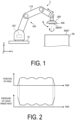
- FIG. 1 is a diagram illustrating an example of an outer appearance configuration of the liquid droplet discharge system according to the embodiment.
- a liquid droplet discharge system 1 includes a robotic arm (an example of a robot unit) 100, a control unit 120. a circulation device 200, and a liquid droplet discharge head 300.
- the robotic arm 100 is assembled on a base 10 mounted on, for example, a horizontal floor surface indoors or outdoors.
- the robotic arm 100 includes an arm portion 110.
- the arm portion 110 includes a plurality of parts that are bent and stretched and rotatably assembled.
- the arm portion 110 can operate the liquid droplet discharge head 300 (and the circulation device 200) mounted on a tip of the arm portion 110 in accordance with a command from a control unit 120.
- the arm portion 110 can move the liquid droplet discharge head 300 (and the circulation device 200) mounted on the tip of the arm portion 110 in accordance with the command from the control unit 120. This allows the arm portion 110 to change the position of the liquid droplet discharge head 300 (and the circulation device 200).
- the arm portion 110 can rotate the liquid droplet discharge head 300 (and the circulation device 200) around a predetermined rotation axis (for example, a Y axis or a Z axis). This allows the arm portion 110 to change the posture of the liquid droplet discharge head 300 (and the circulation device 200) such as the orientation and the angle thereof.
- the arm portion 110 can perform various operations of the liquid droplet discharge head 300 (and the circulation device 200) including swing, tilt, reversal, and the like thereof.
- the arm portion 110 illustrated in FIG. 1 is not particularly limited to the configuration illustrated in FIG. 1 as long as the arm portion 110 is provided with a degree of freedom with which the liquid droplet discharge head 300 can change the position and posture as necessary.
- the control unit 120 is built in, for example, the robotic arm 100 (arm portion 110).
- the control unit 120 may be mounted on an external device independent from the robotic arm 100, and may be communicably connected to the robotic arm 100.
- the control unit 120 controls the operation of the arm portion 110 by outputting a command to control the operation of the arm portion 110 to an actuator or the like that drives the arm portion 110.
- the control unit 120 is provided with a control device 121 (see FIG. 6 ) such as a processor and a storage device 122 (see FIG. 6 ) such as a memory.
- the storage device 122 stores, for example, a first control program 131 (see FIG. 6 ) for controlling an operation of the robotic arm 100, a second control program (see FIG.
- the control device 121 controls the operation of the robotic arm 100 (arm portion 110) based on a program, data, and the like stored in the storage device 122.
- the robotic arm 100 can change the position in a vertical direction (z axis direction) of the liquid droplet discharge head 300 by moving the circulation device 200 and the liquid droplet discharge head 300 that are mounted on the tip of the arm portion 110 along a predetermined vertical axis (Z axis) by using the arm portion 110.
- This allows the circulation device 200 and the liquid droplet discharge head 300 to, for example, assume a posture in which, as illustrated in FIG. 1 , a discharge surface 300SF for the liquid included in the liquid droplet discharge head 300 faces parallel to a spraying surface 50SF of an object 50.
- the robotic arm 100 can, for example, cause the arm portion 110 to rotate the circulation device 200 and the liquid droplet discharge head 300 around a predetermined rotation axis, the circulation device 200 and the liquid droplet discharge head 300 being assembled on the tip of the arm portion 110.
- This allows the circulation device 200 and the liquid droplet discharge head 300 to, for example, switch a position in a longitudinal direction and a position in a lateral direction, or to invert an upper position and a lower position.
- the circulation device 200 is installed at a tip portion of the arm portion 110 of the robotic arm 100.
- the circulation device 200 supplies a liquid to the liquid droplet discharge head 300 while controlling the circulation pressure of the liquid circulating between the circulation device 200 and the liquid droplet discharge head 300.
- the liquid droplet discharge head 300 is assembled on the circulation device 200 installed at the tip portion of the arm portion 110 of the robotic arm 100.
- the liquid droplet discharge head 300 functions as a liquid droplet discharge portion that discharges the liquid to the object 50.
- the circulation pressure of the liquid to be supplied to the liquid droplet discharge head 300 is affected by the operation of the liquid droplet discharge head 300 performed by the robotic arm 100.
- the circulation pressure (pressure) of the liquid inside the liquid droplet discharge head 300 changes, for example, as illustrated in FIG. 2.
- FIG. 2 is a diagram for describing changes in the pressure of the liquid inside the liquid droplet discharge head according to the embodiment.
- the circulation pressure (pressure) of the liquid inside the liquid droplet discharge head 300 changes, the liquid may not be stably discharged from the liquid droplet discharge head 300.
- the present application proposes a liquid droplet discharge system 1 that can flexibly deal with a change in the position of the liquid droplet discharge head 300 to keep the appropriate circulation pressure of the liquid to be discharged.
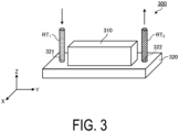
- FIG. 3 is a perspective view schematically illustrating an outer appearance configuration of the liquid droplet discharge head according to the embodiment.
- FIG. 4 is a plan view of the liquid droplet discharge head according to the embodiment.
- FIG. 5 is a diagram schematically illustrating channels inside the liquid droplet discharge head according to the embodiment.
- the liquid droplet discharge head 300 includes a housing including a box-shaped member 310 and a substantially plate-shaped member 320.
- the housing of the liquid droplet discharge head 300 includes a first channel RT 1 installed in the housing to supply a liquid from the circulation device 200 to the inside of the head and a second channel RT 2 installed in the housing to deliver the liquid recovered inside the head back to the circulation device 200.
- a member 320 of the liquid droplet discharge head 300 includes a supply port 321 through which the liquid is supplied to the inside of the head through the first channel RT 1 and a discharge port 322 through which the liquid is recovered from the inside of the head through the second channel RT 2 .
- the liquid droplet discharge head 300 includes a supply reservoir 301, a supply manifold 302, a recovery manifold 303, a recovery reservoir 304, and an element 305.
- the supply reservoir 301 has an elongated shape extending in a longitudinal direction (Y axis direction) of the liquid droplet discharge head 300 and connects to the supply manifold 302.
- the supply reservoir 301 includes a channel inside. As illustrated in FIG. 4 or FIG. 5 , the liquid supplied to the supply reservoir 301 through the first channel RT 1 and the supply port 321 and reserved in the channel of the supply reservoir 301 is delivered to the supply manifold 302.
- the supply manifold 302 has an elongated shape extending in a lateral direction (X axis direction) of the liquid droplet discharge head 300 to a position before the recovery reservoir 304.
- the supply manifold 302 internally includes a channel that communicates with the channel included in the supply reservoir 301 and with the element portion 305. As illustrated in FIG. 4 or FIG. 5 , the liquid delivered from the supply reservoir 301 to the supply manifold 302 is delivered from the supply manifold 302 to the element 305.
- the recovery manifold 303 has an elongated shape extending in the lateral direction (X axis direction) of the liquid droplet discharge head 300 to a position before the supply reservoir 301.
- the recovery manifold 303 internally includes a channel that communicates with a channel included in the recovery reservoir 304 and with the element portion 305. As illustrated in FIG. 4 or FIG. 5 , the liquid having not been discharged from the element 305 (discharge hole 305h) to the outside is delivered to the recovery manifold 303.
- the recovery reservoir 304 has an elongated shape extending in the longitudinal direction (Y axis direction) of the liquid droplet discharge head 300 and is connected to the recovery manifold 303.
- the recovery reservoir 304 includes the channel inside. As illustrated in FIG. 4 or FIG. 5 , the liquid delivered from the recovery manifold 303 to the recovery reservoir 304 and reserved in the channel of the recovery reservoir 304 is delivered back to the circulation device 200 through the recovery port 322 and the second channel RT 2 .
- the element 305 includes a discharge hole 305h.
- the element 305 for example, sucks the liquid from the supply manifold 302 by negative pressure generated in a pressure chamber not illustrated and discharges the liquid thus sucked from the discharge hole 305h toward the object 50 by positive pressure generated in the pressure chamber not illustrated.
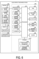
- FIG. 6 is a block diagram illustrating an example of the functional configuration of the liquid droplet discharge system according to the embodiment.
- FIG. 7 is a diagram schematically illustrating a circulation mechanism of the circulation device of the liquid droplet discharge system according to the embodiment.
- FIG. 6 illustrates an example of the functional configuration of the liquid droplet discharge system 1 and that the embodiment need not be limited to the particular example illustrated in FIG. 6 , provided that the configuration can achieve the various functions of the liquid droplet discharge system 1 according to the embodiment.
- FIG. 6 illustrates, in functional blocks, components provided in the liquid droplet discharge system 1 according to the embodiment and omits a description of other components in general.
- the constitutional elements of the liquid droplet discharge system 1 illustrated in FIG. 6 are functional concepts and are not limited to the example illustrated in FIG. 6 , and are not necessarily physically configured as illustrated.
- the specific form of distribution and integration of each of the functional blocks is not limited to that illustrated, and all or a portion thereof can be functionally or physically distributed and integrated in any unit, depending on various loads, usage conditions, and the like.
- the liquid droplet discharge system 1 includes the circulation device 200.
- the circulation device 200 includes a tank 201, a discharge pump 202, a suction pump 203, a first proportional valve 204, a second proportional valve 205, and a heater 206.
- the circulation device 200 also includes an input/output interface 207, a first pressure sensor 208, a second pressure sensor 209, a third pressure sensor 210, a fourth pressure sensor 211, and a flowmeter 212.
- the circulation device 200 further includes a storage 214 and a processor 215.
- the storage 214 and the processor 215 may be mounted independently of the circulation device 200.
- the liquid droplet discharge system 1 includes the robotic arm 100, the control unit 120, and the liquid droplet discharge head 300.
- the circulation device 200 includes the first channel RT 1 and the second channel RT 2 .
- the first channel RT 1 is a channel communicating the tank 201 and the liquid droplet discharge head 300 with each other to allow the liquid reserved in the tank 201 to flow into the liquid droplet discharge head 300.
- the second channel RT 2 is a channel communicating the tank 201 and the liquid droplet discharge head 300 with each other to allow the liquid that has flowed into the liquid droplet discharge head 300 to return to the tank 201.
- the liquid recovered in the liquid droplet discharge head 300 without being discharged from the liquid droplet discharge head 300 to the outside is fed back through the second channel RT 2 to the tank 201.
- the first channel RT 1 and the second channel RT 2 can be implemented, for example, by a pipe made of a predetermined material that does not interact with constituents of the liquid.
- a processor 215 of the circulation device 200 including the components described above controls the circulation pressure of the liquid circulating clockwise between the tank 201 and the liquid droplet discharge head 300.
- the tank 201 reserves the liquid supplied to the liquid droplet discharge head 300.
- the tank 201 functions as a reserve portion for storing the liquid supplied to the liquid droplet discharge head 300.
- the discharge pump 202 feeds the liquid reserved in the tank 201 through the first channel RT 1 to the liquid droplet discharge head 300.
- the discharge pump 202 generates positive pressure for feeding the liquid reserved in the tank 201 to the liquid droplet discharge head 300.
- the discharge pump 202 can, for example, feed the liquid reserved in the tank 201 to the liquid droplet discharge head 300 at a predetermined constant supply pressure.
- the suction pump 203 feeds, through the second channel RT 2 , the liquid recovered in the liquid droplet discharge head 300 to the tank 201.
- the suction pump 203 generates negative pressure used to suck and feed the liquid recovered in the liquid droplet discharge head 300, back to the tank 201.
- the suction pump 203 can, for example, feed the liquid sucked from the liquid droplet discharge head 300 to the tank 201 at a predetermined constant recovery pressure.
- the discharge pump 202 and the suction pump 203 can each be implemented by a rotary pump such as a gear pump or a displacement pump such as a diaphragm pump.
- the first proportional valve 204 functions as a first valve portion interposed in the first channel RT 1 between the tank 201 and the liquid droplet discharge head 300 to proportionally control the flow rate of the liquid supplied to the liquid droplet discharge head 300.
- the first proportional valve 204 can continuously modify the channel cross-sectional area for the liquid between 0 and 100%, and controls the flow rate of the liquid to a desired flow rate.
- the first proportional valve 204 can reduce the supply pressure when supplying the liquid to the liquid droplet discharge head 300 by reducing the channel cross-sectional area for the liquid.
- the first proportional valve 204 can increase the supply pressure when supplying the liquid to the liquid droplet discharge head 300 by increasing the channel cross-sectional area for the liquid.
- the second proportional valve 205 functions as a second valve portion interposed in the second channel RT 2 between the tank 201 and the liquid droplet discharge head 300 to proportionally control the flow rate of the liquid fed from the liquid droplet discharge head 300 to the tank 201.
- the second proportional valve 205 can continuously modify the channel cross-sectional area for the liquid between 0 and 100%, and controls the flow rate of the liquid to a desired flow rate.
- the second proportional valve 205 can reduce the recovery pressure when recovering the liquid from the liquid droplet discharge head 300 by reducing the channel cross-sectional area for the liquid.
- the second proportional valve 205 can increase the recovery pressure when recovering the liquid from the liquid droplet discharge head 300 by increasing the channel cross-sectional area for the liquid.
- the first proportional valve 204 and the second proportional valve 205 can be implemented by a proportional selector valve of an electromagnetic type or a proportional selector valve of a pneumatic type.
- the heater 206 is provided in the first channel RT 1 or adjacent to the first channel RT 1 , and heats the liquid flowing through the first channel RT 1 .
- the input/output interface 207 exchanges various types of information with the control unit 120 of the robotic arm 100.
- the input/output interface 207 can, for example, receive a signal indicating the start of the discharge of the liquid from the control unit 120 and a signal indicating the end of the discharge of the liquid.
- the input/output interface 207 can acquire information about the operation of the liquid droplet discharge head 300 from the first control program 131 stored in the storage device 122 of the control unit 120.
- the information related to the operation of the liquid droplet discharge head 300 for example, numerical values related to the movement of the liquid droplet discharge head 300 are acquired.
- Examples of the numerical values related to the movement of the liquid droplet discharge head 300 include the position of the liquid droplet discharge head 300 in the vertical direction, the vertical acceleration acting on the liquid droplet discharge head 300, and the horizontal acceleration acting on the liquid droplet discharge head 300.
- the information regarding the operation of the liquid droplet discharge head 300 may be, for example, numerical values regarding various operations of the liquid droplet discharge head 300 including swing, tilt, reversal, and the like thereof.
- the input/output interface 207 functions as an acquiring unit that acquires information related to the operation of the liquid droplet discharge head 300 from the first control program 131 controlling the operation of the robotic arm 100 that performs the operation of the liquid droplet discharge head 300.
- the first pressure sensor 208 measures the pressure of the liquid fed by the discharge pump 202 from the tank 201 to the liquid droplet discharge head 300.
- the first pressure sensor 208 measures the pressure downstream of the discharge pump 202 in a circulation direction of the liquid in the circulation device 200.
- the first pressure sensor 208 sends a measurement result to the processor 215.
- the second pressure sensor 209 measures the pressure of the liquid that is sucked from the liquid droplet discharge head 300 by the suction pump 203 and fed to the tank 201.
- the second pressure sensor 209 measures the pressure upstream of the suction pump 203 in the circulation direction of the liquid in the circulation device 200.
- the second pressure sensor 209 sends a measurement result to the processor 215.
- the third pressure sensor 210 functions as a first pressure measuring portion that measures, through the first channel RT 1 , the pressure of the liquid flowing between the first proportional valve 204 and the liquid droplet discharge head 300 as the supply pressure.
- the third pressure sensor 210 measures the pressure of the liquid immediately before the liquid flows into the liquid droplet discharge head 300 after passing through the first proportional valve 204. That is, the third pressure sensor 210 measures the pressure downstream of the first proportional valve 204 in the circulation direction of the liquid in the circulation device 200 as a supply pressure.
- the third pressure sensor 210 sends a measurement result to the processor 215.
- the fourth pressure sensor 211 functions as a second pressure measuring portion that measures, through the second channel RT 2 , the pressure of the liquid flowing between the second proportional valve 205 and the liquid droplet discharge head 300 as the recovery pressure.
- the fourth pressure sensor 211 measures the pressure of the liquid immediately after the liquid is fed from the liquid droplet discharge head 300 toward the tank 201 and before the liquid passes through the second proportional valve 205. That is, the fourth pressure sensor 211 measures the pressure upstream of the second proportional valve 205 in the circulation direction of the liquid in the circulation device 200 as the recovery pressure.
- the fourth pressure sensor 211 sends a measurement result to the processor 215.
- the flowmeter 212 measures the flow rate of the liquid fed to the liquid droplet discharge head 300.
- the flowmeter 212 sends a measurement result to the processor 215.
- the storage 214 stores programs and data necessary for various processes of the liquid droplet discharge system 1 (here, the circulation device 200).
- the storage 214 stores, for example, pump control information 241 and pressure adjustment information 242.
- the pump control information 241 is set in advance and used for pump control.
- the data for pump control includes, for example, a target value of pressure (positive pressure) applied to the liquid that the discharge pump 202 feeds and a target value of pressure (negative pressure) applied to the liquid that the suction pump 203 sucks.
- the target value of the positive pressure of the discharge pump 202 is preset to, for example, a value approximately 1.2 to 3 times higher than the pressure at which the liquid is supplied to the liquid droplet discharge head 300.
- the target value for the negative pressure of the suction pump 203 is preset to a value approximately 1.2 to 3 times lower than the pressure at which the liquid is supplied to the liquid droplet discharge head 300.
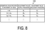
- the pressure adjustment information 242 is data in which the adjustment value for the supply pressure and the adjustment value for the recovery pressure for suppressing a change in the pressure of the liquid inside the liquid droplet discharge head 300 are each associated with the numerical value related to the movement of the liquid droplet discharge head 300 on a per magnitude basis.
- FIG. 8 is a diagram illustrating an overview of the pressure adjustment information according to the embodiment.
- the pressure adjustment information 242 includes the item “numerical value related to head movement”, the item “adjustment value (supply pressure)", and the item “adjustment value (recovery pressure)”, and these items are associated with one another.
- the item “numerical value related to head movement” stores, as a numerical value related to the movement of the liquid droplet discharge head 300, the position of the liquid droplet discharge head 300 in the vertical direction, the vertical acceleration acting on the liquid droplet discharge head 300, or the horizontal acceleration acting on the liquid droplet discharge head 300.
- the item “adjustment value (supply pressure)” stores a target value used when the supply pressure is adjusted (hereinafter also referred to as “adjustment value” as appropriate).
- the item “adjustment value (recovery pressure)” stores a target value used when the recovery pressure is adjusted (hereinafter also referred to as “adjustment value” as appropriate).
- a change in the position in the vertical direction and the like of the liquid droplet discharge head 300 may cause a hydraulic head pressure to act on the liquid circulating inside the head, changing the circulation pressure of the liquid circulating inside the head, and making the discharge of the liquid from the liquid droplet discharge head 300 unstable.
- An experiment, a simulation, or the like is performed to obtain in advance the relationship between a change in the position or the like of the liquid droplet discharge head 300 in the vertical direction and the adjustment value for the supply pressure and the adjustment value for the recovery pressure which are used to keep the pressure of the liquid inside the head constant.
- the supply pressure can be obtained from the measurement result obtained by the third pressure sensor 210.
- the recovery pressure can be obtained from the measurement result obtained by the fourth pressure sensor 211.
- the adjustment value for the supply pressure and the adjustment value for the recovery pressure are stored in the pressure adjustment information 242 in association with the numerical value indicating the position of the liquid droplet discharge head 300 in the vertical direction or the like on a per magnitude basis.
- the pressure adjustment information 242 may be prepared in accordance with the type of the numerical value related to the movement of the liquid droplet discharge head 300. That is, the pressure adjustment information 242 may be individually prepared for each of the position of the liquid droplet discharge head 300 in the vertical direction, the vertical acceleration acting on the liquid droplet discharge head 300, and the horizontal acceleration acting on the liquid droplet discharge head 300.
- the processor 215 executes various processing operations in the liquid droplet discharge system 1 (here, the circulation device 200) based on programs, data, and the like that are stored in the storage 214.
- the processor 215 implements various functions for controlling the components of the liquid droplet discharge system 1 (here, the circulation device 200) by reading out and executing the computer program stored in the storage 214.
- the processor 215 makes an adjustment to keep constant the positive pressure applied to the liquid that the discharge pump 202 feeds based on the measurement result of the first pressure sensor 208 and the measurement result of the third pressure sensor 210. For example, the processor 215 adjusts the positive pressure of the discharge pump 202 in such a manner that the pressure of the liquid obtained from the measurement result of the first pressure sensor 208 remains approximately 1.2 to 3 times larger than the pressure of the liquid obtained from the measurement result of the third pressure sensor 210.
- the processor 215 makes an adjustment to keep constant the negative pressure applied to the liquid that the suction pump 203 sucks based on the measurement results of the second pressure sensor 209 and the fourth pressure sensor 211. For example, the processor 215 adjusts the negative pressure of the suction pump 203 in such a manner that the pressure of the liquid obtained from the measurement result of the second pressure sensor 209 remains approximately 1.2 to 3 times lower than the pressure of the liquid obtained from the measurement result of the fourth pressure sensor 211.
- the processor 215 circulates the liquid between the tank 201 and the liquid droplet discharge head 300 by adjusting and keeping constant the differential pressure between the positive pressure that the discharge pump 202 applies to the liquid and the negative pressure that the suction pump 203 applies to the liquid.
- the processor 215 controls the first proportional valve 204 and the second proportional valve 205 based on the numerical value obtained by the input/output interface 207 to adjust the supply pressure and the recovery pressure.
- a method of controlling the first proportional valve 204 and the second proportional valve 205 will be described below using FIG. 9 to FIG. 11 .
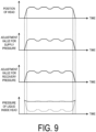
- FIG. 9 is a diagram for describing a method of controlling the first proportional valve and the second proportional valve based on the position of the liquid droplet discharge head according to the embodiment.
- the first row from the top of FIG. 9 schematically illustrates an example of the relationship between time and the position of the liquid droplet discharge head 300 in the vertical direction.
- the second and third rows from the top of FIG. 9 schematically illustrate an example of the relationship between time and the adjustment value for the supply pressure and the adjustment value for the recovery pressure.
- the fourth row from the top of FIG. 9 schematically illustrates an example of the relationship between time and the circulation pressure of the liquid inside the liquid droplet discharge head 300.
- the posture of the liquid droplet discharge head 300 is assumed to be a posture in which the discharge surface 300SF for the liquid is directed vertically downward (see FIG. 1 ).
- the circulation pressure of the liquid inside the liquid droplet discharge head 300 is predicted to change due to the hydraulic head pressure acting on the liquid circulating inside the head.
- a graph of a broken line indicates changes in the circulation pressure of the liquid inside the liquid droplet discharge head 300 due to the effect of the hydraulic head pressure.
- the processor 215 controls the input/output interface 207 to acquire the position of the liquid droplet discharge head 300 in the vertical direction. Specifically, the input/output interface 207 acquires the position of the liquid droplet discharge head 300 in the vertical direction from the first control program 131 as a numerical value related to the movement of the liquid droplet discharge head 300.
- the processor 215 adjusts the supply pressure and the recovery pressure to keep constant the circulation pressure (pressure) of the liquid inside the liquid droplet discharge head 300, the circulation pressure of the liquid changing depending on the acquired position of the liquid droplet discharge head 300.
- the circulation pressure (pressure) of the liquid becomes constant is a concept including not only a case where the pressure of the liquid becomes strictly constant but also a case where the pressure of the liquid approaches a constant value.
- the processor 215 may adjust the supply pressure and the recovery pressure in such a manner that the circulation pressure (pressure) of the liquid inside the liquid droplet discharge head 300 approaches a constant value.
- the processor 215 may adjust the supply pressure and the recovery pressure to reduce the circulation pressure when the pressure in the head increases, and may adjust the supply pressure and the recovery pressure to increase the circulation pressure when the pressure in the head decreases.
- the circulation pressure (pressure) of the liquid inside the liquid droplet discharge head 300 is predicted to decrease with increasing height of the position of the liquid droplet discharge head 300 due to the effect of the hydraulic head pressure.
- both the supply pressure and the recovery pressure need to be increased to cancel the effect of the hydraulic head pressure.
- the processor 215 refers to the pressure adjustment information 242 to determine the adjustment value for the supply pressure and the adjustment value for the recovery pressure corresponding to the acquired position of the liquid droplet discharge head 300.
- the adjustment value for the supply pressure and the adjustment value for the recovery pressure increase consistently with the height of the position of the liquid droplet discharge head 300.
- the processor 215 increases the flow rate of a fluid passing through the first proportional valve 204 by widening the channel cross-sectional area of the first proportional valve 204 in order to increase the supply pressure to a target pressure based on the determined adjustment value.
- the processor 215 increases the flow rate of the fluid passing through the second proportional valve 205 by widening the channel cross-sectional area of the second proportional valve 205 in order to increase the recovery pressure to a target pressure based on the determined adjustment value.
- the circulation pressure (pressure) of the liquid inside the liquid droplet discharge head 300 is predicted to increase with decreasing height of the position of the liquid droplet discharge head 300 due to the effect of the hydraulic head pressure.
- both the supply pressure and the recovery pressure need to be reduced to cancel the effect of the hydraulic head pressure.
- the processor 215 refers to the pressure adjustment information 242 to determine the adjustment values for the supply pressure and the recovery pressure corresponding to the acquired position of the liquid droplet ejection head 300.
- the adjustment value for the supply pressure and the adjustment value for the recovery pressure decrease consistently with the height of the position of the liquid droplet discharge head 300.
- the processor 215 reduces the flow rate of the fluid passing through the first proportional valve 204 by narrowing the channel cross-sectional area of the first proportional valve 204 in order to reduce the supply pressure to a target pressure based on the determined adjustment value.
- the processor 215 reduces the flow rate of the fluid passing through the second proportional valve 205 by narrowing the channel cross-sectional area of the second proportional valve 205 in order to reduce the recovery pressure to a target pressure based on the determined adjustment value.
- the processor 215 can increase or reduce the flow rate of the fluid passing through the first proportional valve 204 and the second proportional valve 205 in accordance with the position of the liquid droplet discharge head 300 in the vertical direction. As a result, the processor 215 can keep the circulation pressure (pressure) of the liquid inside the liquid droplet discharge head 300 constant.
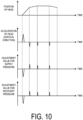
- FIG. 10 is a diagram for describing the method of controlling the first proportional valve and the second proportional valve based on the vertical acceleration acting on the liquid droplet discharge head according to the embodiment.
- the first row from the top of FIG. 10 schematically illustrates an example of the relationship between time and the position of the liquid droplet discharge head 300 in the vertical direction.
- the second row from the top of FIG. 10 schematically illustrates an example of the relationship between time and the vertical acceleration acting on the liquid droplet discharge head 300.
- the third and fourth rows from the top of FIG. 10 schematically illustrate an example of the relationship between time and the adjustment value for the supply pressure and the adjustment value for the recovery pressure.
- the posture of the liquid droplet discharge head 300 is assumed to be a posture in which the discharge surface 300SF for the liquid is directed vertically downward (see FIG. 1 ).
- the circulation pressure (pressure) of the liquid inside the liquid droplet discharge head 300 is predicted to change when the liquid droplet discharge head 300 moves to change the acceleration of the liquid droplet discharge head 300 due to the hydraulic head pressure acting on the liquid circulating inside the head.
- the circulation pressure (pressure) of the liquid inside the liquid droplet discharge head 300 changes, the liquid may not be stably discharged from the liquid droplet discharge head 300.
- the processor 215 controls the input/output interface 207 to acquire the vertical acceleration acting on the liquid droplet discharge head 300. Specifically, the input/output interface 207 acquires the vertical acceleration acting on the liquid droplet discharge head 300, from the first control program 131 as a numerical value related to the movement of the liquid droplet discharge head 300.
- the processor 215 adjusts the supply pressure and the recovery pressure to keep constant the circulation pressure (pressure) of the liquid inside the liquid droplet discharge head 300, the circulation pressure of the liquid changing according to the acquired vertical acceleration.
- the circulation pressure (pressure) of the liquid inside the liquid droplet discharge head 300 is predicted to increase as the acceleration of the liquid droplet discharge head 300 in the vertically upward direction increases due to the effect of the hydraulic head pressure.
- both the supply pressure and the recovery pressure need to be reduced to cancel the effect of the hydraulic head pressure.
- the processor 215 determines the adjustment value for the supply pressure and the adjustment value for the recovery pressure corresponding to the acquired vertical acceleration with reference to the pressure adjustment information 242.
- the adjustment value for the supply pressure and the adjustment value for the recovery pressure decrease as the vertically upward acceleration of the liquid droplet discharge head 300 increases.
- the processor 215 reduces the flow rate of the fluid passing through the first proportional valve 204 by narrowing the channel cross-sectional area of the first proportional valve 204 in order to reduce the supply pressure to a target pressure based on the determined adjustment value.
- the processor 215 reduces the flow rate of the fluid passing through the second proportional valve 205 by narrowing the channel cross-sectional area of the second proportional valve 205 in order to reduce the recovery pressure to a target pressure based on the determined adjustment value.
- the circulation pressure (pressure) of the liquid inside the liquid droplet discharge head 300 is predicted to decrease as the acceleration of the liquid droplet discharge head 300 in the vertically upward direction decreases due to the effect of the hydraulic head pressure.
- both the supply pressure and the recovery pressure need to be increased to cancel the effect of the hydraulic head pressure.
- the processor 215 refers to the pressure adjustment information 242 to determine the adjustment value for the supply pressure and the adjustment value for the recovery pressure corresponding to the acquired position of the liquid droplet discharge head 300. The adjustment value for each of the supply pressure and the recovery pressure increases as the vertically upward acceleration of the liquid droplet discharge head 300 decreases.
- the processor 215 increases the flow rate of a fluid passing through the first proportional valve 204 by widening the channel cross-sectional area of the first proportional valve 204 in order to increase the supply pressure to a target pressure based on the determined adjustment value.
- the processor 215 increases the flow rate of the fluid passing through the second proportional valve 205 by widening the channel cross-sectional area of the second proportional valve 205 in order to increase the recovery pressure to a target pressure based on the determined adjustment value.
- the processor 215 can increase or decrease the flow rate of the fluid passing through the first proportional valve 204 and the second proportional valve 205 in accordance with the vertical acceleration acting on the droplet discharge head 300. As a result, the processor 215 can keep the circulation pressure (pressure) of the liquid inside the liquid droplet discharge head 300 constant.
- FIG. 11 is a diagram for describing the method of controlling the first proportional valve and the second proportional valve based on the acceleration acting on the liquid droplet horizontal discharge head according to the embodiment.
- the first row from the top of FIG. 11 schematically illustrates an example of the relationship between time and the position of the liquid droplet discharge head 300 in the horizontal direction.
- the second row from the top of FIG. 10 schematically illustrates an example of the relationship between time and the horizontal acceleration acting on the liquid droplet discharge head 300.
- the third and fourth rows from the top of FIG. 10 schematically illustrate an example of the relationship between time and the adjustment value for the supply pressure and the adjustment value for the recovery pressure.
- the posture of the liquid droplet discharge head 300 is assumed to be a posture in which the discharge surface 300SF for the liquid is directed vertically downward (see FIG. 1 ).
- the horizontal acceleration acting on the liquid droplet discharge head 300 is the acceleration in the direction from the downstream side to the upstream side of the liquid flowing inside the liquid droplet discharge head 300.
- the downstream side is a recovery side (that is, a recovery port 322 side) on which the liquid is recovered from the liquid droplet discharge head 300
- the upstream side is a supply side (that is, a supply port 321 side) on which the liquid is supplied to the liquid droplet discharge head 300.
- the circulation pressure (pressure) of the liquid inside the liquid droplet discharge head 300 is predicted to change when the liquid droplet discharge head 300 moves to change the acceleration of the liquid droplet discharge head 300, due to the hydraulic head pressure acting on the liquid circulating inside the head.
- the circulation pressure (pressure) of the liquid inside the liquid droplet discharge head 300 changes, the liquid may not be stably discharged from the liquid droplet discharge head 300.
- the processor 215 controls the input/output interface 207 to acquire the horizontal acceleration acting on the liquid droplet discharge head 300. Specifically, the input/output interface 207 acquires the horizontal acceleration acting on the liquid droplet discharge head 300, from the first control program 131 as a numerical value related to the movement of the liquid droplet discharge head 300.
- the processor 215 adjusts the supply pressure and the recovery pressure to keep constant the circulation pressure (pressure) of the liquid inside the liquid droplet discharge head 300, the circulation pressure of the liquid changing according to the acquired horizontal acceleration.
- the upstream pressure of the liquid flowing inside the liquid droplet discharge head 300 is predicted to become higher than the downstream pressure with progression of the acceleration in the direction from the downstream side toward the upstream side of the liquid flowing inside the liquid droplet discharge head 300 due to the effect of the hydraulic head pressure.
- the processor 215 refers to the pressure adjustment information 242 to determine the adjustment value for the supply pressure and the adjustment value for the recovery pressure corresponding to the acquired horizontal acceleration.
- the adjustment value for the supply pressure decreases with increasing acceleration in the direction from the downstream side toward the upstream side of the liquid flowing inside the liquid droplet discharge head 300.
- the adjustment value for the recovery pressure increases consistently with the acceleration in the direction from the downstream side toward the upstream side of the liquid flowing inside the liquid droplet discharge head 300.
- the processor 215 reduces the flow rate of the fluid passing through the first proportional valve 204 by narrowing the channel cross-sectional area of the first proportional valve 204 in order to reduce the supply pressure to a target pressure based on the determined adjustment value.
- the processor 215 increases the flow rate of the fluid passing through the second proportional valve 205 by widening the channel cross-sectional area of the second proportional valve 205 in order to increase the recovery pressure to a target pressure based on the determined adjustment value.
- the upstream pressure of the liquid flowing inside the liquid droplet discharge head 300 is predicted to become lower than the downstream pressure with decreasing acceleration in the direction from the downstream side toward the upstream side of the liquid flowing inside the liquid droplet discharge head 300 due to the effect of the hydraulic head pressure.
- the processor 215 refers to the pressure adjustment information 242 to determine the adjustment value for the supply pressure and the adjustment value for the recovery pressure corresponding to the acquired horizontal acceleration.
- the adjustment value for the supply pressure increases with decreasing acceleration in the direction from the downstream side toward the upstream side of the liquid flowing inside the liquid droplet discharge head 300.
- the adjustment value for the recovery pressure decreases consistently with the acceleration in the direction from the downstream side toward the upstream side of the liquid flowing inside the liquid droplet discharge head 300.
- the processor 215 increases the flow rate of a fluid passing through the first proportional valve 204 by widening the channel cross-sectional area of the first proportional valve 204 in order to increase the supply pressure to a target pressure based on the determined adjustment value.
- the processor 215 reduces the flow rate of the fluid passing through the second proportional valve 205 by narrowing the channel cross-sectional area of the second proportional valve 205 in order to reduce the recovery pressure to a target pressure based on the determined adjustment value.
- the processor 215 can increase or reduce the flow rate of the fluid passing through the first proportional valve 204 and the second proportional valve 205 in accordance with the horizontal acceleration acting on the droplet discharge head 300. As a result, the processor 215 can keep the circulation pressure (pressure) of the liquid inside the liquid droplet discharge head 300 constant.
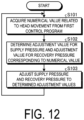
- FIG. 12 is a flowchart illustrating an example of the processing procedure of the liquid droplet discharge system according to the embodiment.
- the processing illustrated in FIG. 12 is executed by the processor 215.
- the processing illustrated in FIG. 12 is repeatedly executed during the operation of the liquid droplet discharge system 1.
- the processor 215 controls the input/output interface 207 to acquire, from the first control program 131, the numerical value related to the movement of the liquid droplet discharge head 300 (step S101). That is, the input/output interface 207 acquires, as the numerical value, at least one selected from the group consisting of the position of the liquid droplet discharge head 300 in the vertical direction, the vertical acceleration acting on the liquid droplet discharge head 300, and the horizontal acceleration acting on the liquid droplet discharge head 300.
- the processor 215 refers to the pressure adjustment information 242 and determines the adjustment values for the supply pressure and recovery pressure corresponding to the acquired numerical values (step S 102).
- the processor 215 adjusts, to the determined adjustment values, the supply pressure and the recovery pressure of the liquid circulating between the tank 201 and the liquid droplet discharge head 300 (step S103), and returns to the processing procedure of the step S101.
- FIG. 13 is a diagram illustrating an example of a functional configuration of the liquid droplet discharge system according to such another embodiment. Since the circulation mechanism of a circulation device 200A in the liquid droplet discharge system 1 according to such another embodiment is the same as the circulation mechanism of the circulation device 200 in the liquid droplet discharge system 1 according to the embodiment illustrated in FIG. 7 , description thereof will be omitted.
- the liquid droplet discharge system 1 includes the circulation device 200A.
- the circulation device 200A includes an input/output interface 207A instead of the input/output interface 207 illustrated in FIG. 6 .
- the circulation device 200A includes a storage 214A and a processor 215A instead of the storage 214 and the processor 215 illustrated in FIG. 6 .
- the input/output interface 207A exchanges various types of information with the control unit 120 of the robotic arm 100.
- the input/output interface 207A can acquire the numerical value related to the movement of the liquid droplet discharge head 300 from the first control program 131 stored in the storage device 122 of the control unit 120.
- the input/output interface 207A can further acquire a printing rate of the liquid droplet discharge head 300 from the second control program 132 stored in the storage device 122 of the control unit 120.
- the "printing rate” refers to, for example, the ratio (S1/S2) of the integrated area S 1 of the liquid discharged onto the object 50 to the area S2 of the spraying surface 50SF of the object 50, and may be calculated from image data to be printed.
- the input/output interface 207A functions as an acquiring unit that acquires the printing rate of the liquid droplet discharge head 300 from the second control program 132 that controls the operation related to the discharge of the liquid droplet discharge head 300.
- the storage 214A stores programs and data necessary for various processing operations of the liquid droplet discharge system 1 (here, the circulation device 200A).
- the storage 214A stores, for example, the pump control information 241, first pressure adjustment information 242A, and second pressure adjustment information 243A.
- the pump control information 241 has a data structure being the same as or similar to that of the pump control information 241 illustrated in FIG. 6 .
- the first pressure adjustment information 242A has a data structure being the same as or similar to that of the pressure adjustment information 242 illustrated in FIG. 6 .
- the adjustment value for the supply pressure and the adjustment value for the recovery pressure for suppressing changes in the pressures of the liquid inside the liquid droplet discharge head 300 are associated with the printing rate of the liquid droplet discharge heads 300 on a per magnitude basis.
- FIG. 14 is a diagram illustrating an overview of the second pressure adjustment information according to such another embodiment.
- the second pressure adjustment information 243A includes the item “printing rate”, the item “adjustment value (supply pressure)", and the item “adjustment value (recovery pressure)”, and these items are associated with one another.
- the item “printing rate” stores the printing rate of the liquid droplet discharge head 300.
- the item “adjustment value (supply pressure)” stores a target value used when the supply pressure is adjusted (hereinafter also referred to as “adjustment value” as appropriate).
- the item “adjustment value (recovery pressure)” stores a target value used when the recovery pressure is adjusted (hereinafter also referred to as “adjustment value” as appropriate).
- a change in the printing rate of the liquid droplet discharge head 300 may change the circulation pressure (pressure) of the liquid circulating inside the head, making discharge from the liquid droplet discharge head 300 unstable.
- An experiment, a simulation, or the like is performed to obtain in advance the relationship between a change in the printing rate of the liquid droplet discharge head 300 and the adjustment value for the supply pressure and the adjustment value for the recovery pressure which are used to keep the pressure of the liquid inside the head constant.
- the supply pressure can be obtained from the measurement result obtained by the third pressure sensor 210.
- the recovery pressure can be obtained from the measurement result obtained by the fourth pressure sensor 211.
- the adjustment value for the supply pressure and the adjustment value for the recovery pressure are stored in the second pressure adjustment information 243A in association with the printing rate of the liquid droplet discharge head 300 on a per magnitude basis.
- the processor 215A controls the first proportional valve 204 and the second proportional valve 205 based on the numerical value acquired by the input/output interface 207A to adjust the supply pressure and the recovery pressure. In parallel with the adjustment of the supply pressure and the recovery pressure based on the numerical value, the processor 215A controls the first proportional valve 204 and the second proportional valve 205 based on the printing rate acquired by the input/output interface 207A to adjust the supply pressure and the recovery pressure. In other words, the processor 215A performs the adjustment of the supply pressure and the recovery pressure based on the numerical value related to the operation of the liquid droplet discharge head 300 in parallel with the adjustment of the supply pressure and the recovery pressure based on the printing rate of the liquid droplet discharge head 300.
- the method of controlling the first proportional valve 204 and the second proportional valve 205 based on the printing rate of the liquid droplet discharge head 300 will be described.
- the circulation pressure (pressure) of the liquid inside the liquid droplet discharge head 300 is predicted to change due to the hydraulic head pressure acting on the liquid circulating inside the head.
- the circulation pressure (pressure) of the liquid inside the liquid droplet discharge head 300 is predicted to change.
- the circulation pressure (pressure) of the liquid inside the liquid droplet discharge head 300 changes, the liquid may not be stably discharged from the liquid droplet discharge head 300.
- the processor 215A controls the input/output interface 207 to acquire the numerical value related to the movement of the liquid droplet discharge head 300. Specifically, the input/output interface 207 acquires the position of the liquid droplet discharge head 300 in the vertical direction and the like from the first control program 131 as a numerical value related to the movement of the liquid droplet discharge head 300. The processor 215A controls the input/output interface 207A to acquire the printing rate of the liquid droplet discharge head 300. To be more specific, the input/output interface 207A acquires the printing rate of the liquid droplet discharge head 300 from the second control program 132.
- the processor 215A adjusts the supply pressure and the recovery pressure to keep constant the circulation pressure (pressures) of the liquid inside the liquid droplet discharge heads 300, the circulation pressure of the liquid changing depending on the acquired position of the liquid droplet discharge head 300.
- the method of controlling the first proportional valve 204 and the second proportional valve 205 based on the position of the liquid droplet discharge head 300 and the like is the same as or similar to the method of controlling illustrated in FIG. 9 to FIG. 11 .
- the processor 215A adjusts the supply pressure and the recovery pressure to keep constant the circulation pressure (pressures) of the liquid inside the liquid droplet discharge heads 300, the circulation pressure of the liquid changing according to the acquired printing rate of the liquid droplet discharge head 300.
- both the supply pressure and the recovery pressure need to be increased to compensate for the insufficient supply of the liquid.
- the processor 215A refers to the second pressure adjustment information 243A to determine the adjustment value for the supply pressure and the adjustment value for the recovery pressure corresponding to the acquired printing rate of the liquid droplet discharge head 300.
- the adjustment value for the supply pressure and the adjustment value for the recovery pressure increase consistently with the printing rate of the liquid droplet discharge head 300.
- the processor 215A increases the flow rate of the fluid passing through the first proportional valve 204 by widening the channel cross-sectional area of the first proportional valve 204 in order to increase the supply pressure to a target pressure based on the determined adjustment value.
- the processor 215A increases the flow rate of the fluid passing through the second proportional valve 205 by widening the channel cross-sectional area of the second proportional valve 205 in order to increase the recovery pressure to a target pressure based on the determined adjustment value.
- the processor 215A can increase or reduce the flow rate of the fluid passing through the first proportional valve 204 and the second proportional valve 205 in accordance with the printing rate of the liquid droplet discharge head 300.
- the processor 215A can keep the circulation pressure (pressure) of the liquid inside the liquid droplet discharge head 300 constant.
- FIG. 15 is a flowchart illustrating an example of the processing procedure of the liquid droplet discharge system according to such another embodiment.
- the processing illustrated in FIG. 15 is executed by the processor 215A.
- the processing illustrated in FIG. 15 is repeatedly executed during the operation of the liquid droplet discharge system 1.
- the processor 215A controls the input/output interface 207A to acquire, from the first control program 131, a numerical value related to the movement of the liquid droplet discharge head 300 (step S201). That is, the input/output interface 207A acquires, as the numerical value, at least one selected from the group consisting of the position of the liquid droplet discharge head 300 in the vertical direction, the vertical acceleration acting on the liquid droplet discharge head 300, and the horizontal acceleration acting on the liquid droplet discharge head 300.
- the processor 215A controls the input/output interface 207A to acquire the printing rate of the liquid droplet discharge head 300 from the second control program 132 (step S202).
- the processor 215A refers to the first pressure adjustment information 242A to determine the adjustment values for the supply pressure and recovery pressure corresponding to the acquired numerical value (step S203).
- the processor 215A adjusts, to the determined adjustment values, the supply pressure and the recovery pressure of the liquid circulating between the tank 201 and the liquid droplet discharge head 300 (step S204), and returns to the processing procedure of the step S201.
- the processor 215A performs the processing procedure of steps S205 to S206 based on the printing rate of the liquid droplet discharge head 300 while overlapping with the processing procedure of steps S203 to S204 based on the numerical value related to the operation of the liquid droplet discharge head 300.
- the processor 215A refers to the second pressure adjustment information 243A to determine the adjustment value for the supply pressure and the adjustment value for the recovery pressure corresponding to the acquired printing rate of the liquid droplet discharge head 300 (step S205).
- the processor 215A adjusts the supply pressure and the recovery pressure of the liquid circulating between the tank 201 and the liquid droplet discharge head 300 to the determined adjustment value (step S206), and returns to the processing procedure of the step S201.
- the processor 215A can determine that no hydraulic head pressure sufficient to affect the circulation pressure of the liquid circulating through the liquid droplet discharge head 300 has been generated. In this case, the processor 215A may stop the adjustment of the supply pressure and the recovery pressure based on the numerical value related to the operation of the liquid droplet discharge head 300 (the processing procedure of steps S203 to S204). That is, the processor 215A performs only the adjustment of the supply pressure and the recovery pressure based on the printing rate of the liquid droplet discharge head 300 (the processing procedure of steps S205 to S206) when no hydraulic head pressures sufficient to affect the circulation pressure of the liquid circulating through the liquid droplet discharge head 300 has been generated.
- the circulation pressure (pressure) of the liquid inside the liquid droplet discharge head 300 can be kept constant while suppressing an increase in the processing load.
- the liquid droplet discharge system 1 may use the flowmeter 212 connected to the first channel RT1 to measure the flow rate of the liquid supplied to the liquid droplet discharge head 300, and compare the measured flow rate of the liquid with the discharge amount obtained from the printing rate. When the discharge amount obtained from the printing rate is larger than the flow rate of the liquid measured by the flowmeter 212, the liquid droplet discharge system 1 may adjust the supply pressure and the recovery pressure so as to not increase or to decrease the circulation pressure.
- the processor 215A when determining the adjustment value for the supply pressure and the adjustment value for the recovery pressure corresponding to the acquired printing rate of the liquid droplet discharge head 300 (step S205), the processor 215A obtains the discharge amount assumed from the printing rate and also acquires the flow rate of the liquid measured by the flowmeter 212. Then, the processor 215A compares the discharge amount obtained from the printing rate with the flow rate of the liquid measured by the flowmeter 212. When the discharge amount obtained from the printing rate is larger than the flow rate of the liquid measured by the flowmeter 212, the processor 215A may control the first and second proportional valves 204 and 205 so as to not increase the circulation pressure or to decrease the circulation pressure.
- the discharge amount may be reduced due to non-discharge of liquid droplets caused by bubbles or foreign matter in many channels (discharge holes 305h).
- the circulation pressure may be adjusted to increase based on the information of the printing rate (see S205 and S206 in FIG. 15 ).
- the printing rate refers to, for example, the ratio (S1/S2) of the integrated area S1 of the liquid discharged onto the object 50 to the area S2 of the spraying surface 50SF of the object 50.
- the internal pressure of the liquid droplet discharge head 300 becomes inappropriately high, which may cause problems such as ink overflowing from the discharge hole 305h.
- the expected discharge amount is calculated from the printing rate, and the value of the expected discharge amount is compared with the measurement value of the flowmeter 212.
- the circulation pressure is preferably caused to not increase or to decrease.
- the discharge amount assumed from the printing rate is normally smaller than the measurement value of the flowmeter 212. Since the measurement value of the flowmeter 212 is the sum of the discharge amount and the circulation flow rate during discharge, the discharge amount assumed from the printing rate is normally smaller than the measurement value of the flowmeter 212. On the other hand, a state in which the discharge amount obtained from the printing rate as described above is larger than the flow rate measured by the flowmeter 212 is an abnormal state.
- the coating apparatus for example, the liquid droplet discharge system 1
- the coating apparatus includes a reserve portion (for example, the tank 201), a robot unit (for example, the robotic arm 100), a first channel (for example, the first channel RT 1 ), a second channel (for example, the second channel RT 2 ), an acquiring unit (for example, the input/output interface 207 or 207A), and a controller (for example, the processor 215 or 215A).
- the reserve portion stores liquid to be supplied to the liquid droplet discharge portion (for example, the liquid droplet discharge head 300).
- the robot unit operates the liquid droplet discharge portion.
- the first channel is a channel through which the reserve portion and the liquid droplet discharge portion are in communication with each other, the channel being configured to cause the liquid reserved in the reserve portion to flow into the liquid droplet discharge portion.
- the second channel is a channel through which the reserve portion and the liquid droplet discharge portion are in communication with each other, the channel being configured to cause the liquid having flowed into the liquid droplet discharge portion to flow back to the reserve portion.
- the acquiring unit acquires information on the operation of the liquid droplet discharge portion from a program (for example, the first control program 131) controlling the operation of the robot unit.
- the controller controls a circulation pressure of the liquid circulating between the reserve portion and the liquid droplet discharge portion.
- the controller controls the circulation pressure based on the information related to the operation.
- the coating apparatus may further include a first valve portion (for example, the first proportional valve 204), a second valve portion (for example, the second proportional valve 205), a first pressure measuring portion (for example, the third pressure sensor 210), and a second pressure measuring portion (for example, the fourth pressure sensor 211).
- the first valve portion may be interposed in the first channel and may control the flow rate of the liquid fed from the reserve portion to the liquid droplet discharge portion.
- the second valve portion may be interposed in the second channel and may control the flow rate of the liquid fed from the liquid droplet discharge portion to the reserve portion.
- the first pressure measuring portion may measure, through the first channel, the fluid pressure of the liquid flowing between the first valve portion and the liquid droplet discharge portion as a supply pressure.
- the second pressure measuring portion may measure, through the second channel, the fluid pressure of the liquid flowing between the second valve portion and the liquid droplet discharge portion as a recovery pressure.
- the acquiring unit may acquire the numerical value related to the movement of the liquid droplet discharge portion from a program controlling the operation of the robot unit.
- the controller may control the first valve portion and the second valve portion based on a numerical value acquired by the acquiring unit, and may adjust the supply pressure and the recovery pressure.
- the acquiring unit may acquire the position of the liquid droplet discharge portion in the vertical direction as a numerical value.
- the controller may adjust the supply pressure and the recovery pressure to keep constant the pressure of the liquid inside the liquid droplet discharge portion, the pressure of the liquid changing depending on the position.
- the adjustment value for the supply pressure and the adjustment value for the recovery pressure may increase with increase in height of the position.
- the acquiring unit may acquire, as the numerical value, the vertical acceleration acting on the liquid droplet discharge portion.
- the controller may adjust the supply pressure and the recovery pressure to keep constant the pressure of the liquid inside the liquid droplet discharge portion, the pressure of the liquid changing according to the vertical acceleration.
- the adjustment value for the supply pressure and the adjustment value for the recovery pressure may decrease with increase in the vertically upward acceleration.
- the coating apparatus according to the embodiment can adjust the supply pressure and the recovery pressure of the liquid in such a manner that even when the liquid circulating through the liquid droplet discharge portion is affected by hydraulic head pressure due to a change in the vertical acceleration acting on the liquid droplet discharge portion, the effect of the hydraulic head pressure is canceled out.
- the acquiring unit may acquire the horizontal acceleration acting on the liquid droplet discharge portion as the numerical value.
- the controller may adjust the supply pressure and the recovery pressure to keep constant the pressure of the liquid inside the liquid droplet discharge portion, the pressure of the liquid changing depending on the horizontal acceleration.
- the adjustment value for the supply pressure may decrease with increase in the acceleration in a direction from a downstream side to an upstream side of the liquid flowing inside the liquid droplet discharge portion.
- the adjustment value for the recovery pressure may increase with increase in the acceleration in the direction from the downstream side to the upstream side of the liquid flowing inside the liquid droplet discharge portion.
- the coating apparatus can adjust the supply pressure and the recovery pressure of the liquid in such a manner that even when the liquid circulating through the liquid droplet discharge portion is affected by the hydraulic head pressure due to a change in the horizontal acceleration acting on the liquid droplet discharge portion, the effect of the hydraulic head pressure can be canceled out.
- the coating apparatus may further include a storage (for example, the storage 214).
- the storage may store pressure adjustment information (for example, the pressure adjustment information 242) in which the adjustment value for the supply pressure and the adjustment value for the recovery pressure for suppressing a change in the pressure of the liquid inside the liquid droplet discharge portion is associated with the numerical value for each of magnitudes of the numerical value.
- the controller may adjust the supply pressure and the recovery pressure to the adjustment values corresponding to the numerical value acquired by the acquiring unit.
- the coating apparatus can adjust the supply pressure and the recovery pressure of the liquid in such a manner that even when the liquid circulating through the liquid droplet discharge portion is affected by the hydraulic head pressure due to a change in any of various numeral values related to the movement of the liquid droplet discharge portion, the effect of the hydraulic head pressure is canceled out.
- the acquiring unit may further acquire a printing rate of the liquid droplet discharge portion from a program (for example, the second control program 132) controlling an operation, related to the discharge, of the liquid droplet discharge portion.
- the controller (for example, the processor 215A) may adjust the supply pressure and the recovery pressure based on the numerical value acquired by the acquiring unit and may adjust the supply pressure and the recovery pressure based on the printing rate acquired by the acquiring unit.
- the coating apparatus of the embodiment can appropriately maintain the circulation pressure even when the circulation pressure of the liquid supplied to the liquid droplet discharge portion is affected by the movement of the liquid discharge portion caused by the robot unit or the printing rate of the liquid droplet discharge portion.
- the controller may adjust the supply pressure and the recovery pressure to keep constant the pressure of the liquid inside the liquid droplet discharge portion, the pressure of the liquid changing depending on the printing rate of the liquid droplet discharge portion.
- the adjustment value for the supply pressure and the adjustment value for the recovery pressure may increase with increase in the printing rate of the liquid droplet discharge portion.
- the coating apparatus according to the embodiment can adjust the supply pressure and the recovery pressure of the liquid to compensate for the insufficient supply of the liquid due to a change in the printing rate of the liquid droplet discharge head.
- the coating apparatus may further include a storage (for example, the storage 214A).
- the storage may store first pressure adjustment information (for example, the first pressure adjustment information 242A) in which adjustment value for the supply pressure and the adjustment value for the recovery pressure for suppressing a change in the pressure of the liquid inside the liquid droplet discharge portion are associated with the numerical value for each of magnitudes of the numerical value, and second pressure adjustment information (for example, the second pressure adjustment information 243A) in which the adjustment value for the supply pressure and the adjustment value for the recovery pressure for suppressing a change in the pressure of the liquid inside the liquid droplet discharge portion are associated with the printing rate of the liquid droplet discharge portion for each of magnitudes of the printing rate.
- first pressure adjustment information for example, the first pressure adjustment information 242A
- second pressure adjustment information for example, the second pressure adjustment information 243A
- the controller may adjust the supply pressure and the recovery pressure to the adjustment values corresponding to the numerical value acquired by the acquiring unit.
- the controller may refer to the second pressure adjustment information to adjust the supply pressure and the recovery pressure to the adjustment value corresponding to the printing rate acquired by the acquiring unit.
- the coating apparatus of the embodiment can perform the adjustment of the supply pressure and the recovery pressure based on any of various numerical values related to the movement of the liquid droplet discharge portion in parallel with the adjustment of the supply pressure and the recovery pressure based on the printing rate of the liquid droplet discharge portion.
- the controller may stop the adjustment of the supply pressure and the recovery pressure based on the numerical value.
- the coating apparatus of the embodiment can appropriately maintain the circulation pressure while suppressing an increase in the processing load.
Landscapes
- Chemical & Material Sciences (AREA)
- Analytical Chemistry (AREA)
- Engineering & Computer Science (AREA)
- Robotics (AREA)
- Physics & Mathematics (AREA)
- Fluid Mechanics (AREA)
- Coating Apparatus (AREA)
- Ink Jet (AREA)
- Application Of Or Painting With Fluid Materials (AREA)
- Spray Control Apparatus (AREA)
Abstract
Description
- Disclosed embodiments relate to a coating apparatus and a coating method.
- Inkjet printers and inkjet plotters utilizing an inkjet recording method are known as printing devices. A droplet discharge head for discharging liquid is installed in such printing devices utilizing an inkjet method.
- For inkjet printing devices, a technique of controlling the pressure of a liquid supplied to a liquid droplet discharge head has been proposed.
- Patent Document 1:
JP 2010-12432 A - In one aspect of an embodiment, a coating apparatus includes a reserve portion, a robot unit, a first channel, a second channel, an acquiring unit, and a controller. The reserve portion reserves a liquid to be supplied to a liquid droplet discharge portion. The robot unit operates the liquid droplet discharge portion. The first channel is a channel through which the reserve portion and the liquid droplet discharge portion are in communication with each other, the channel being configured to cause the liquid reserved in the reserve portion to flow into the liquid droplet discharge portion. The second channel is a channel through which the reserve portion and the liquid droplet discharge portion are in communication with each other, the channel being configured to cause the liquid having flowed into the liquid droplet discharge portion to flow back to the reserve portion. The acquiring unit acquires information related to an operation of the liquid droplet discharge portion from a program controlling an operation of the robot unit. The controller controls a circulation pressure of the liquid circulating between the reserve portion and the liquid droplet discharge portion. The controller controls the circulation pressure, based on the information related to the operation.
-
-
FIG. 1 is a diagram illustrating an example of an outer appearance configuration of a liquid droplet discharge system according to an embodiment. -
FIG. 2 is a diagram for describing changes in the pressure of a liquid inside a liquid droplet discharge head according to the embodiment. -
FIG. 3 is a perspective view schematically illustrating an outer appearance configuration of the liquid droplet discharge head according to the embodiment. -
FIG. 4 is a plan view illustrating the liquid droplet discharge head according to the embodiment. -
FIG. 5 is a diagram schematically illustrating a channel inside the liquid droplet discharge head according to the embodiment. -
FIG. 6 is a block diagram illustrating an example of a functional configuration of the liquid droplet discharge system according to the embodiment. -
FIG. 7 is a diagram schematically illustrating a circulation mechanism of a circulation device in the liquid droplet discharge system according to the embodiment. -
FIG. 8 is a diagram illustrating an overview of pressure adjustment information according to the embodiment. -
FIG. 9 is a diagram for describing a method of controlling a first proportional valve and a second proportional valve based on the position of the liquid droplet discharge head according to the embodiment. -
FIG. 10 is a diagram for describing the method of controlling the first proportional valve and the second proportional valve based on vertical acceleration acting on the liquid droplet discharge head according to the embodiment. -
FIG. 11 is a diagram for describing the method of controlling the first proportional valve and the second proportional valve based on horizontal acceleration acting on the liquid droplet discharge head according to the embodiment. -
FIG. 12 is a flowchart illustrating an example of a processing procedure of the liquid droplet discharge system according to the embodiment. -
FIG. 13 is a block diagram illustrating an example of a functional configuration of a liquid droplet discharge system according to another embodiment. -
FIG. 14 is a diagram illustrating an outline of second pressure adjustment information according to such another embodiment. -
FIG. 15 is a flowchart illustrating an example of a processing procedure of the liquid droplet discharge system according to such another embodiment. - Embodiments of a coating apparatus and a coating method disclosed in the present application will be described below with reference to the accompanying drawings. Note that the present disclosure is not limited by the following embodiments. Note that the drawings are schematic and that the dimensional relationships between elements, the proportions of the elements, and the like may differ from the actual ones. There may be differences between the drawings in terms of dimensional relationships, proportions, and the like.
- Embodiments can be appropriately combined so as not to contradict each other in terms of processing content. In the following embodiments, the same portions are denoted by the same reference signs, and redundant explanations are omitted.
- The following embodiment describes, as an example of the coating device disclosed by the present application, a liquid droplet discharge system in which a liquid droplet discharge head that discharges liquid (or a liquid droplet) by using an inkjet method is mounted on a robotic arm. The coating device disclosed by the present application can be applied to inkjet printers and inkjet plotters that utilize an inkjet recording method as well as various devices that discharge liquid (or liquid droplet) by using an inkjet method.
- Example of Outer Appearance Configuration of Liquid Droplet Discharge System An outer appearance configuration of a liquid droplet discharge system according to an embodiment will be described with reference to
FIG. 1. FIG. 1 is a diagram illustrating an example of an outer appearance configuration of the liquid droplet discharge system according to the embodiment. - As illustrated in
FIG. 1 , a liquiddroplet discharge system 1 includes a robotic arm (an example of a robot unit) 100, acontrol unit 120. acirculation device 200, and a liquiddroplet discharge head 300. - The
robotic arm 100 is assembled on abase 10 mounted on, for example, a horizontal floor surface indoors or outdoors. Therobotic arm 100 includes anarm portion 110. Thearm portion 110 includes a plurality of parts that are bent and stretched and rotatably assembled. Thearm portion 110 can operate the liquid droplet discharge head 300 (and the circulation device 200) mounted on a tip of thearm portion 110 in accordance with a command from acontrol unit 120. For example, thearm portion 110 can move the liquid droplet discharge head 300 (and the circulation device 200) mounted on the tip of thearm portion 110 in accordance with the command from thecontrol unit 120. This allows thearm portion 110 to change the position of the liquid droplet discharge head 300 (and the circulation device 200). For example, in accordance with the command from thecontrol unit 120, thearm portion 110 can rotate the liquid droplet discharge head 300 (and the circulation device 200) around a predetermined rotation axis (for example, a Y axis or a Z axis). This allows thearm portion 110 to change the posture of the liquid droplet discharge head 300 (and the circulation device 200) such as the orientation and the angle thereof. For example, in accordance with the command from thecontrol unit 120, thearm portion 110 can perform various operations of the liquid droplet discharge head 300 (and the circulation device 200) including swing, tilt, reversal, and the like thereof. Thearm portion 110 illustrated inFIG. 1 is not particularly limited to the configuration illustrated inFIG. 1 as long as thearm portion 110 is provided with a degree of freedom with which the liquiddroplet discharge head 300 can change the position and posture as necessary. - The
control unit 120 is built in, for example, the robotic arm 100 (arm portion 110). Thecontrol unit 120 may be mounted on an external device independent from therobotic arm 100, and may be communicably connected to therobotic arm 100. Thecontrol unit 120 controls the operation of thearm portion 110 by outputting a command to control the operation of thearm portion 110 to an actuator or the like that drives thearm portion 110. Thecontrol unit 120 is provided with a control device 121 (seeFIG. 6 ) such as a processor and a storage device 122 (seeFIG. 6 ) such as a memory. The storage device 122 stores, for example, a first control program 131 (seeFIG. 6 ) for controlling an operation of therobotic arm 100, a second control program (seeFIG. 6 ) for controlling an operation related to discharge of the liquid droplet discharge head 300 (hereinafter also referred to as a discharge operation), and the like. Thecontrol device 121 controls the operation of the robotic arm 100 (arm portion 110) based on a program, data, and the like stored in the storage device 122. - The
robotic arm 100 can change the position in a vertical direction (z axis direction) of the liquiddroplet discharge head 300 by moving thecirculation device 200 and the liquiddroplet discharge head 300 that are mounted on the tip of thearm portion 110 along a predetermined vertical axis (Z axis) by using thearm portion 110. This allows thecirculation device 200 and the liquiddroplet discharge head 300 to, for example, assume a posture in which, as illustrated inFIG. 1 , a discharge surface 300SF for the liquid included in the liquiddroplet discharge head 300 faces parallel to a spraying surface 50SF of anobject 50. Therobotic arm 100 can, for example, cause thearm portion 110 to rotate thecirculation device 200 and the liquiddroplet discharge head 300 around a predetermined rotation axis, thecirculation device 200 and the liquiddroplet discharge head 300 being assembled on the tip of thearm portion 110. This allows thecirculation device 200 and the liquiddroplet discharge head 300 to, for example, switch a position in a longitudinal direction and a position in a lateral direction, or to invert an upper position and a lower position. - The
circulation device 200 is installed at a tip portion of thearm portion 110 of therobotic arm 100. Thecirculation device 200 supplies a liquid to the liquiddroplet discharge head 300 while controlling the circulation pressure of the liquid circulating between thecirculation device 200 and the liquiddroplet discharge head 300. The liquiddroplet discharge head 300 is assembled on thecirculation device 200 installed at the tip portion of thearm portion 110 of therobotic arm 100. The liquiddroplet discharge head 300 functions as a liquid droplet discharge portion that discharges the liquid to theobject 50. - The circulation pressure of the liquid to be supplied to the liquid
droplet discharge head 300 is affected by the operation of the liquiddroplet discharge head 300 performed by therobotic arm 100. When the liquiddroplet discharge head 300 is operated by therobotic arm 100 to change the position of the liquiddroplet discharge head 300, the circulation pressure (pressure) of the liquid inside the liquiddroplet discharge head 300 changes, for example, as illustrated inFIG. 2. FIG. 2 is a diagram for describing changes in the pressure of the liquid inside the liquid droplet discharge head according to the embodiment. When the circulation pressure (pressure) of the liquid inside the liquiddroplet discharge head 300 changes, the liquid may not be stably discharged from the liquiddroplet discharge head 300. In view of this, the present application proposes a liquiddroplet discharge system 1 that can flexibly deal with a change in the position of the liquiddroplet discharge head 300 to keep the appropriate circulation pressure of the liquid to be discharged. - The liquid
droplet discharge head 300 according to the embodiment will be described withFIG. 3 to FIG. 5 .FIG. 3 is a perspective view schematically illustrating an outer appearance configuration of the liquid droplet discharge head according to the embodiment.FIG. 4 is a plan view of the liquid droplet discharge head according to the embodiment.FIG. 5 is a diagram schematically illustrating channels inside the liquid droplet discharge head according to the embodiment. - As illustrated in
FIG. 3 , the liquiddroplet discharge head 300 includes a housing including a box-shapedmember 310 and a substantially plate-shapedmember 320. The housing of the liquiddroplet discharge head 300 includes a first channel RT1 installed in the housing to supply a liquid from thecirculation device 200 to the inside of the head and a second channel RT2 installed in the housing to deliver the liquid recovered inside the head back to thecirculation device 200. As illustrated inFIG. 3 orFIG. 4 , amember 320 of the liquiddroplet discharge head 300 includes asupply port 321 through which the liquid is supplied to the inside of the head through the first channel RT1 and adischarge port 322 through which the liquid is recovered from the inside of the head through the second channel RT2. - As illustrated in
FIG. 4 , the liquiddroplet discharge head 300 includes asupply reservoir 301, asupply manifold 302, arecovery manifold 303, arecovery reservoir 304, and anelement 305. - The
supply reservoir 301 has an elongated shape extending in a longitudinal direction (Y axis direction) of the liquiddroplet discharge head 300 and connects to thesupply manifold 302. Thesupply reservoir 301 includes a channel inside. As illustrated inFIG. 4 or FIG. 5 , the liquid supplied to thesupply reservoir 301 through the first channel RT1 and thesupply port 321 and reserved in the channel of thesupply reservoir 301 is delivered to thesupply manifold 302. - The
supply manifold 302 has an elongated shape extending in a lateral direction (X axis direction) of the liquiddroplet discharge head 300 to a position before therecovery reservoir 304. Thesupply manifold 302 internally includes a channel that communicates with the channel included in thesupply reservoir 301 and with theelement portion 305. As illustrated inFIG. 4 or FIG. 5 , the liquid delivered from thesupply reservoir 301 to thesupply manifold 302 is delivered from thesupply manifold 302 to theelement 305. - The
recovery manifold 303 has an elongated shape extending in the lateral direction (X axis direction) of the liquiddroplet discharge head 300 to a position before thesupply reservoir 301. Therecovery manifold 303 internally includes a channel that communicates with a channel included in therecovery reservoir 304 and with theelement portion 305. As illustrated inFIG. 4 or FIG. 5 , the liquid having not been discharged from the element 305 (discharge hole 305h) to the outside is delivered to therecovery manifold 303. - The
recovery reservoir 304 has an elongated shape extending in the longitudinal direction (Y axis direction) of the liquiddroplet discharge head 300 and is connected to therecovery manifold 303. Therecovery reservoir 304 includes the channel inside. As illustrated inFIG. 4 or FIG. 5 , the liquid delivered from therecovery manifold 303 to therecovery reservoir 304 and reserved in the channel of therecovery reservoir 304 is delivered back to thecirculation device 200 through therecovery port 322 and the second channel RT2. - The
element 305 includes adischarge hole 305h. Theelement 305, for example, sucks the liquid from thesupply manifold 302 by negative pressure generated in a pressure chamber not illustrated and discharges the liquid thus sucked from thedischarge hole 305h toward theobject 50 by positive pressure generated in the pressure chamber not illustrated. - Example of Functional Configuration of Liquid Droplet Discharge System A functional configuration of the liquid
droplet discharge system 1 according to the embodiment will be described.FIG. 6 is a block diagram illustrating an example of the functional configuration of the liquid droplet discharge system according to the embodiment.FIG. 7 is a diagram schematically illustrating a circulation mechanism of the circulation device of the liquid droplet discharge system according to the embodiment. - Note that
FIG. 6 illustrates an example of the functional configuration of the liquiddroplet discharge system 1 and that the embodiment need not be limited to the particular example illustrated inFIG. 6 , provided that the configuration can achieve the various functions of the liquiddroplet discharge system 1 according to the embodiment.FIG. 6 illustrates, in functional blocks, components provided in the liquiddroplet discharge system 1 according to the embodiment and omits a description of other components in general. The constitutional elements of the liquiddroplet discharge system 1 illustrated inFIG. 6 are functional concepts and are not limited to the example illustrated inFIG. 6 , and are not necessarily physically configured as illustrated. For example, the specific form of distribution and integration of each of the functional blocks is not limited to that illustrated, and all or a portion thereof can be functionally or physically distributed and integrated in any unit, depending on various loads, usage conditions, and the like. - As illustrated in
FIG. 6 , the liquiddroplet discharge system 1 includes thecirculation device 200. Thecirculation device 200 includes atank 201, adischarge pump 202, asuction pump 203, a firstproportional valve 204, a secondproportional valve 205, and aheater 206. Thecirculation device 200 also includes an input/output interface 207, afirst pressure sensor 208, asecond pressure sensor 209, athird pressure sensor 210, afourth pressure sensor 211, and aflowmeter 212. Thecirculation device 200 further includes astorage 214 and aprocessor 215. Thestorage 214 and theprocessor 215 may be mounted independently of thecirculation device 200. The liquiddroplet discharge system 1 includes therobotic arm 100, thecontrol unit 120, and the liquiddroplet discharge head 300. - As illustrated in
FIG. 7 , thecirculation device 200 includes the first channel RT1 and the second channel RT2. The first channel RT1 is a channel communicating thetank 201 and the liquiddroplet discharge head 300 with each other to allow the liquid reserved in thetank 201 to flow into the liquiddroplet discharge head 300. The second channel RT2 is a channel communicating thetank 201 and the liquiddroplet discharge head 300 with each other to allow the liquid that has flowed into the liquiddroplet discharge head 300 to return to thetank 201. The liquid recovered in the liquiddroplet discharge head 300 without being discharged from the liquiddroplet discharge head 300 to the outside is fed back through the second channel RT2 to thetank 201. The first channel RT1 and the second channel RT2 can be implemented, for example, by a pipe made of a predetermined material that does not interact with constituents of the liquid. As illustrated inFIG. 7 , for example, aprocessor 215 of thecirculation device 200 including the components described above controls the circulation pressure of the liquid circulating clockwise between thetank 201 and the liquiddroplet discharge head 300. - The
tank 201 reserves the liquid supplied to the liquiddroplet discharge head 300. Thetank 201 functions as a reserve portion for storing the liquid supplied to the liquiddroplet discharge head 300. - The
discharge pump 202 feeds the liquid reserved in thetank 201 through the first channel RT1 to the liquiddroplet discharge head 300. Thedischarge pump 202 generates positive pressure for feeding the liquid reserved in thetank 201 to the liquiddroplet discharge head 300. Thedischarge pump 202 can, for example, feed the liquid reserved in thetank 201 to the liquiddroplet discharge head 300 at a predetermined constant supply pressure. - The
suction pump 203 feeds, through the second channel RT2, the liquid recovered in the liquiddroplet discharge head 300 to thetank 201. Thesuction pump 203 generates negative pressure used to suck and feed the liquid recovered in the liquiddroplet discharge head 300, back to thetank 201. Thesuction pump 203 can, for example, feed the liquid sucked from the liquiddroplet discharge head 300 to thetank 201 at a predetermined constant recovery pressure. - The
discharge pump 202 and thesuction pump 203 can each be implemented by a rotary pump such as a gear pump or a displacement pump such as a diaphragm pump. - The first
proportional valve 204 functions as a first valve portion interposed in the first channel RT1 between thetank 201 and the liquiddroplet discharge head 300 to proportionally control the flow rate of the liquid supplied to the liquiddroplet discharge head 300. The firstproportional valve 204 can continuously modify the channel cross-sectional area for the liquid between 0 and 100%, and controls the flow rate of the liquid to a desired flow rate. For example, the firstproportional valve 204 can reduce the supply pressure when supplying the liquid to the liquiddroplet discharge head 300 by reducing the channel cross-sectional area for the liquid. On the other hand, the firstproportional valve 204 can increase the supply pressure when supplying the liquid to the liquiddroplet discharge head 300 by increasing the channel cross-sectional area for the liquid. - The second
proportional valve 205 functions as a second valve portion interposed in the second channel RT2 between thetank 201 and the liquiddroplet discharge head 300 to proportionally control the flow rate of the liquid fed from the liquiddroplet discharge head 300 to thetank 201. The secondproportional valve 205, as with the firstproportional valve 204, can continuously modify the channel cross-sectional area for the liquid between 0 and 100%, and controls the flow rate of the liquid to a desired flow rate. For example, the secondproportional valve 205 can reduce the recovery pressure when recovering the liquid from the liquiddroplet discharge head 300 by reducing the channel cross-sectional area for the liquid. On the other hand, the secondproportional valve 205 can increase the recovery pressure when recovering the liquid from the liquiddroplet discharge head 300 by increasing the channel cross-sectional area for the liquid. - The first
proportional valve 204 and the secondproportional valve 205 can be implemented by a proportional selector valve of an electromagnetic type or a proportional selector valve of a pneumatic type. - The
heater 206 is provided in the first channel RT1 or adjacent to the first channel RT1, and heats the liquid flowing through the first channel RT1. - The input/
output interface 207 exchanges various types of information with thecontrol unit 120 of therobotic arm 100. The input/output interface 207 can, for example, receive a signal indicating the start of the discharge of the liquid from thecontrol unit 120 and a signal indicating the end of the discharge of the liquid. Under the control of theprocessor 215, the input/output interface 207 can acquire information about the operation of the liquiddroplet discharge head 300 from thefirst control program 131 stored in the storage device 122 of thecontrol unit 120. As the information related to the operation of the liquiddroplet discharge head 300, for example, numerical values related to the movement of the liquiddroplet discharge head 300 are acquired. Examples of the numerical values related to the movement of the liquiddroplet discharge head 300 include the position of the liquiddroplet discharge head 300 in the vertical direction, the vertical acceleration acting on the liquiddroplet discharge head 300, and the horizontal acceleration acting on the liquiddroplet discharge head 300. The information regarding the operation of the liquiddroplet discharge head 300 may be, for example, numerical values regarding various operations of the liquiddroplet discharge head 300 including swing, tilt, reversal, and the like thereof. The input/output interface 207 functions as an acquiring unit that acquires information related to the operation of the liquiddroplet discharge head 300 from thefirst control program 131 controlling the operation of therobotic arm 100 that performs the operation of the liquiddroplet discharge head 300. - The
first pressure sensor 208 measures the pressure of the liquid fed by thedischarge pump 202 from thetank 201 to the liquiddroplet discharge head 300. Thefirst pressure sensor 208 measures the pressure downstream of thedischarge pump 202 in a circulation direction of the liquid in thecirculation device 200. Thefirst pressure sensor 208 sends a measurement result to theprocessor 215. - The
second pressure sensor 209 measures the pressure of the liquid that is sucked from the liquiddroplet discharge head 300 by thesuction pump 203 and fed to thetank 201. Thesecond pressure sensor 209 measures the pressure upstream of thesuction pump 203 in the circulation direction of the liquid in thecirculation device 200. Thesecond pressure sensor 209 sends a measurement result to theprocessor 215. - The
third pressure sensor 210 functions as a first pressure measuring portion that measures, through the first channel RT1, the pressure of the liquid flowing between the firstproportional valve 204 and the liquiddroplet discharge head 300 as the supply pressure. Thethird pressure sensor 210 measures the pressure of the liquid immediately before the liquid flows into the liquiddroplet discharge head 300 after passing through the firstproportional valve 204. That is, thethird pressure sensor 210 measures the pressure downstream of the firstproportional valve 204 in the circulation direction of the liquid in thecirculation device 200 as a supply pressure. Thethird pressure sensor 210 sends a measurement result to theprocessor 215. - The
fourth pressure sensor 211 functions as a second pressure measuring portion that measures, through the second channel RT2, the pressure of the liquid flowing between the secondproportional valve 205 and the liquiddroplet discharge head 300 as the recovery pressure. Thefourth pressure sensor 211 measures the pressure of the liquid immediately after the liquid is fed from the liquiddroplet discharge head 300 toward thetank 201 and before the liquid passes through the secondproportional valve 205. That is, thefourth pressure sensor 211 measures the pressure upstream of the secondproportional valve 205 in the circulation direction of the liquid in thecirculation device 200 as the recovery pressure. Thefourth pressure sensor 211 sends a measurement result to theprocessor 215. - The
flowmeter 212 measures the flow rate of the liquid fed to the liquiddroplet discharge head 300. Theflowmeter 212 sends a measurement result to theprocessor 215. - The
storage 214 stores programs and data necessary for various processes of the liquid droplet discharge system 1 (here, the circulation device 200). Thestorage 214 stores, for example, pumpcontrol information 241 andpressure adjustment information 242. - The
pump control information 241 is set in advance and used for pump control. The data for pump control includes, for example, a target value of pressure (positive pressure) applied to the liquid that thedischarge pump 202 feeds and a target value of pressure (negative pressure) applied to the liquid that thesuction pump 203 sucks. When considering the discharge of the liquid from the liquiddroplet discharge head 300, the target value of the positive pressure of thedischarge pump 202 is preset to, for example, a value approximately 1.2 to 3 times higher than the pressure at which the liquid is supplied to the liquiddroplet discharge head 300. In contrast, the target value for the negative pressure of thesuction pump 203 is preset to a value approximately 1.2 to 3 times lower than the pressure at which the liquid is supplied to the liquiddroplet discharge head 300. - The
pressure adjustment information 242 is data in which the adjustment value for the supply pressure and the adjustment value for the recovery pressure for suppressing a change in the pressure of the liquid inside the liquiddroplet discharge head 300 are each associated with the numerical value related to the movement of the liquiddroplet discharge head 300 on a per magnitude basis.FIG. 8 is a diagram illustrating an overview of the pressure adjustment information according to the embodiment. - As illustrated in
FIG. 8 , thepressure adjustment information 242 includes the item "numerical value related to head movement", the item "adjustment value (supply pressure)", and the item "adjustment value (recovery pressure)", and these items are associated with one another. The item "numerical value related to head movement" stores, as a numerical value related to the movement of the liquiddroplet discharge head 300, the position of the liquiddroplet discharge head 300 in the vertical direction, the vertical acceleration acting on the liquiddroplet discharge head 300, or the horizontal acceleration acting on the liquiddroplet discharge head 300. The item "adjustment value (supply pressure)" stores a target value used when the supply pressure is adjusted (hereinafter also referred to as "adjustment value" as appropriate). The item "adjustment value (recovery pressure)" stores a target value used when the recovery pressure is adjusted (hereinafter also referred to as "adjustment value" as appropriate). - A change in the position in the vertical direction and the like of the liquid
droplet discharge head 300 may cause a hydraulic head pressure to act on the liquid circulating inside the head, changing the circulation pressure of the liquid circulating inside the head, and making the discharge of the liquid from the liquiddroplet discharge head 300 unstable. An experiment, a simulation, or the like is performed to obtain in advance the relationship between a change in the position or the like of the liquiddroplet discharge head 300 in the vertical direction and the adjustment value for the supply pressure and the adjustment value for the recovery pressure which are used to keep the pressure of the liquid inside the head constant. The supply pressure can be obtained from the measurement result obtained by thethird pressure sensor 210. The recovery pressure can be obtained from the measurement result obtained by thefourth pressure sensor 211. The adjustment value for the supply pressure and the adjustment value for the recovery pressure are stored in thepressure adjustment information 242 in association with the numerical value indicating the position of the liquiddroplet discharge head 300 in the vertical direction or the like on a per magnitude basis. - Note that the
pressure adjustment information 242 may be prepared in accordance with the type of the numerical value related to the movement of the liquiddroplet discharge head 300. That is, thepressure adjustment information 242 may be individually prepared for each of the position of the liquiddroplet discharge head 300 in the vertical direction, the vertical acceleration acting on the liquiddroplet discharge head 300, and the horizontal acceleration acting on the liquiddroplet discharge head 300. - The
processor 215 executes various processing operations in the liquid droplet discharge system 1 (here, the circulation device 200) based on programs, data, and the like that are stored in thestorage 214. Theprocessor 215 implements various functions for controlling the components of the liquid droplet discharge system 1 (here, the circulation device 200) by reading out and executing the computer program stored in thestorage 214. - The
processor 215 makes an adjustment to keep constant the positive pressure applied to the liquid that thedischarge pump 202 feeds based on the measurement result of thefirst pressure sensor 208 and the measurement result of thethird pressure sensor 210. For example, theprocessor 215 adjusts the positive pressure of thedischarge pump 202 in such a manner that the pressure of the liquid obtained from the measurement result of thefirst pressure sensor 208 remains approximately 1.2 to 3 times larger than the pressure of the liquid obtained from the measurement result of thethird pressure sensor 210. - The
processor 215 makes an adjustment to keep constant the negative pressure applied to the liquid that thesuction pump 203 sucks based on the measurement results of thesecond pressure sensor 209 and thefourth pressure sensor 211. For example, theprocessor 215 adjusts the negative pressure of thesuction pump 203 in such a manner that the pressure of the liquid obtained from the measurement result of thesecond pressure sensor 209 remains approximately 1.2 to 3 times lower than the pressure of the liquid obtained from the measurement result of thefourth pressure sensor 211. - The
processor 215 circulates the liquid between thetank 201 and the liquiddroplet discharge head 300 by adjusting and keeping constant the differential pressure between the positive pressure that thedischarge pump 202 applies to the liquid and the negative pressure that thesuction pump 203 applies to the liquid. - The
processor 215 controls the firstproportional valve 204 and the secondproportional valve 205 based on the numerical value obtained by the input/output interface 207 to adjust the supply pressure and the recovery pressure. A method of controlling the firstproportional valve 204 and the secondproportional valve 205 will be described below usingFIG. 9 to FIG. 11 . -
FIG. 9 is a diagram for describing a method of controlling the first proportional valve and the second proportional valve based on the position of the liquid droplet discharge head according to the embodiment. The first row from the top ofFIG. 9 schematically illustrates an example of the relationship between time and the position of the liquiddroplet discharge head 300 in the vertical direction. The second and third rows from the top ofFIG. 9 schematically illustrate an example of the relationship between time and the adjustment value for the supply pressure and the adjustment value for the recovery pressure. The fourth row from the top ofFIG. 9 schematically illustrates an example of the relationship between time and the circulation pressure of the liquid inside the liquiddroplet discharge head 300. Here, the posture of the liquiddroplet discharge head 300 is assumed to be a posture in which the discharge surface 300SF for the liquid is directed vertically downward (seeFIG. 1 ). - With reference to
FIG. 9 , control performed in a case where the liquiddroplet discharge head 300 moves at a constant speed in the vertical direction will be described. - As illustrated in
FIG. 9 , when the liquiddroplet discharge head 300 moves to change the position of the liquiddroplet discharge head 300, the circulation pressure of the liquid inside the liquiddroplet discharge head 300 is predicted to change due to the hydraulic head pressure acting on the liquid circulating inside the head. InFIG. 9 , a graph of a broken line indicates changes in the circulation pressure of the liquid inside the liquiddroplet discharge head 300 due to the effect of the hydraulic head pressure. When the circulation pressure of the liquid in the liquiddroplet discharge head 300 changes, the liquid may not be stably discharged from the liquiddroplet discharge head 300. - The
processor 215 controls the input/output interface 207 to acquire the position of the liquiddroplet discharge head 300 in the vertical direction. Specifically, the input/output interface 207 acquires the position of the liquiddroplet discharge head 300 in the vertical direction from thefirst control program 131 as a numerical value related to the movement of the liquiddroplet discharge head 300. - The
processor 215 adjusts the supply pressure and the recovery pressure to keep constant the circulation pressure (pressure) of the liquid inside the liquiddroplet discharge head 300, the circulation pressure of the liquid changing depending on the acquired position of the liquiddroplet discharge head 300. Here, "the circulation pressure (pressure) of the liquid becomes constant" is a concept including not only a case where the pressure of the liquid becomes strictly constant but also a case where the pressure of the liquid approaches a constant value. In other words, theprocessor 215 may adjust the supply pressure and the recovery pressure in such a manner that the circulation pressure (pressure) of the liquid inside the liquiddroplet discharge head 300 approaches a constant value. For example, theprocessor 215 may adjust the supply pressure and the recovery pressure to reduce the circulation pressure when the pressure in the head increases, and may adjust the supply pressure and the recovery pressure to increase the circulation pressure when the pressure in the head decreases. - In the example illustrated in
FIG. 9 , the circulation pressure (pressure) of the liquid inside the liquiddroplet discharge head 300 is predicted to decrease with increasing height of the position of the liquiddroplet discharge head 300 due to the effect of the hydraulic head pressure. In order to keep the circulation pressure (pressure) of the liquid inside the liquiddroplet discharge head 300 constant, both the supply pressure and the recovery pressure need to be increased to cancel the effect of the hydraulic head pressure. Theprocessor 215 refers to thepressure adjustment information 242 to determine the adjustment value for the supply pressure and the adjustment value for the recovery pressure corresponding to the acquired position of the liquiddroplet discharge head 300. The adjustment value for the supply pressure and the adjustment value for the recovery pressure increase consistently with the height of the position of the liquiddroplet discharge head 300. While referring to the measurement result of thethird pressure sensor 210, theprocessor 215 increases the flow rate of a fluid passing through the firstproportional valve 204 by widening the channel cross-sectional area of the firstproportional valve 204 in order to increase the supply pressure to a target pressure based on the determined adjustment value. On the other hand, while referring to the measurement result of thefourth pressure sensor 211, theprocessor 215, increases the flow rate of the fluid passing through the secondproportional valve 205 by widening the channel cross-sectional area of the secondproportional valve 205 in order to increase the recovery pressure to a target pressure based on the determined adjustment value. - In the example illustrated in
FIG. 9 , the circulation pressure (pressure) of the liquid inside the liquiddroplet discharge head 300 is predicted to increase with decreasing height of the position of the liquiddroplet discharge head 300 due to the effect of the hydraulic head pressure. In order to keep the circulation pressure (pressure) of the liquid inside the liquiddroplet discharge head 300 constant, both the supply pressure and the recovery pressure need to be reduced to cancel the effect of the hydraulic head pressure. Theprocessor 215 refers to thepressure adjustment information 242 to determine the adjustment values for the supply pressure and the recovery pressure corresponding to the acquired position of the liquiddroplet ejection head 300. The adjustment value for the supply pressure and the adjustment value for the recovery pressure decrease consistently with the height of the position of the liquiddroplet discharge head 300. While referring to the measurement result of thethird pressure sensor 210, theprocessor 215 reduces the flow rate of the fluid passing through the firstproportional valve 204 by narrowing the channel cross-sectional area of the firstproportional valve 204 in order to reduce the supply pressure to a target pressure based on the determined adjustment value. On the other hand, while referring to the measurement result of thefourth pressure sensor 211, theprocessor 215 reduces the flow rate of the fluid passing through the secondproportional valve 205 by narrowing the channel cross-sectional area of the secondproportional valve 205 in order to reduce the recovery pressure to a target pressure based on the determined adjustment value. - In this way, the
processor 215 can increase or reduce the flow rate of the fluid passing through the firstproportional valve 204 and the secondproportional valve 205 in accordance with the position of the liquiddroplet discharge head 300 in the vertical direction. As a result, theprocessor 215 can keep the circulation pressure (pressure) of the liquid inside the liquiddroplet discharge head 300 constant. -
FIG. 10 is a diagram for describing the method of controlling the first proportional valve and the second proportional valve based on the vertical acceleration acting on the liquid droplet discharge head according to the embodiment. The first row from the top ofFIG. 10 schematically illustrates an example of the relationship between time and the position of the liquiddroplet discharge head 300 in the vertical direction. The second row from the top ofFIG. 10 schematically illustrates an example of the relationship between time and the vertical acceleration acting on the liquiddroplet discharge head 300. The third and fourth rows from the top ofFIG. 10 schematically illustrate an example of the relationship between time and the adjustment value for the supply pressure and the adjustment value for the recovery pressure. Here, the posture of the liquiddroplet discharge head 300 is assumed to be a posture in which the discharge surface 300SF for the liquid is directed vertically downward (seeFIG. 1 ). - Control performed when the liquid
droplet discharge head 300 moves while accelerating and decelerating in the vertical direction will be described with reference toFIG. 10 . - As illustrated in
FIG. 10 , the circulation pressure (pressure) of the liquid inside the liquiddroplet discharge head 300 is predicted to change when the liquiddroplet discharge head 300 moves to change the acceleration of the liquiddroplet discharge head 300 due to the hydraulic head pressure acting on the liquid circulating inside the head. When the circulation pressure (pressure) of the liquid inside the liquiddroplet discharge head 300 changes, the liquid may not be stably discharged from the liquiddroplet discharge head 300. - The
processor 215 controls the input/output interface 207 to acquire the vertical acceleration acting on the liquiddroplet discharge head 300. Specifically, the input/output interface 207 acquires the vertical acceleration acting on the liquiddroplet discharge head 300, from thefirst control program 131 as a numerical value related to the movement of the liquiddroplet discharge head 300. - The
processor 215 adjusts the supply pressure and the recovery pressure to keep constant the circulation pressure (pressure) of the liquid inside the liquiddroplet discharge head 300, the circulation pressure of the liquid changing according to the acquired vertical acceleration. - In the example illustrated in
FIG. 10 , the circulation pressure (pressure) of the liquid inside the liquiddroplet discharge head 300 is predicted to increase as the acceleration of the liquiddroplet discharge head 300 in the vertically upward direction increases due to the effect of the hydraulic head pressure. In order to keep the circulation pressure (pressure) of the liquid inside the liquiddroplet discharge head 300 constant, both the supply pressure and the recovery pressure need to be reduced to cancel the effect of the hydraulic head pressure. Theprocessor 215 determines the adjustment value for the supply pressure and the adjustment value for the recovery pressure corresponding to the acquired vertical acceleration with reference to thepressure adjustment information 242. The adjustment value for the supply pressure and the adjustment value for the recovery pressure decrease as the vertically upward acceleration of the liquiddroplet discharge head 300 increases. While referring to the measurement result of thethird pressure sensor 210, theprocessor 215 reduces the flow rate of the fluid passing through the firstproportional valve 204 by narrowing the channel cross-sectional area of the firstproportional valve 204 in order to reduce the supply pressure to a target pressure based on the determined adjustment value. On the other hand, while referring to the measurement result of thefourth pressure sensor 211, theprocessor 215 reduces the flow rate of the fluid passing through the secondproportional valve 205 by narrowing the channel cross-sectional area of the secondproportional valve 205 in order to reduce the recovery pressure to a target pressure based on the determined adjustment value. - In the example illustrated in
FIG. 10 , the circulation pressure (pressure) of the liquid inside the liquiddroplet discharge head 300 is predicted to decrease as the acceleration of the liquiddroplet discharge head 300 in the vertically upward direction decreases due to the effect of the hydraulic head pressure. In order to keep the circulation pressure (pressure) of the liquid inside the liquiddroplet discharge head 300 constant, both the supply pressure and the recovery pressure need to be increased to cancel the effect of the hydraulic head pressure. Theprocessor 215 refers to thepressure adjustment information 242 to determine the adjustment value for the supply pressure and the adjustment value for the recovery pressure corresponding to the acquired position of the liquiddroplet discharge head 300. The adjustment value for each of the supply pressure and the recovery pressure increases as the vertically upward acceleration of the liquiddroplet discharge head 300 decreases. While referring to the measurement result of thethird pressure sensor 210, theprocessor 215 increases the flow rate of a fluid passing through the firstproportional valve 204 by widening the channel cross-sectional area of the firstproportional valve 204 in order to increase the supply pressure to a target pressure based on the determined adjustment value. On the other hand, while referring to the measurement result of thefourth pressure sensor 211, theprocessor 215 increases the flow rate of the fluid passing through the secondproportional valve 205 by widening the channel cross-sectional area of the secondproportional valve 205 in order to increase the recovery pressure to a target pressure based on the determined adjustment value. - In this way, the
processor 215 can increase or decrease the flow rate of the fluid passing through the firstproportional valve 204 and the secondproportional valve 205 in accordance with the vertical acceleration acting on thedroplet discharge head 300. As a result, theprocessor 215 can keep the circulation pressure (pressure) of the liquid inside the liquiddroplet discharge head 300 constant. -
FIG. 11 is a diagram for describing the method of controlling the first proportional valve and the second proportional valve based on the acceleration acting on the liquid droplet horizontal discharge head according to the embodiment. The first row from the top ofFIG. 11 schematically illustrates an example of the relationship between time and the position of the liquiddroplet discharge head 300 in the horizontal direction. The second row from the top ofFIG. 10 schematically illustrates an example of the relationship between time and the horizontal acceleration acting on the liquiddroplet discharge head 300. The third and fourth rows from the top ofFIG. 10 schematically illustrate an example of the relationship between time and the adjustment value for the supply pressure and the adjustment value for the recovery pressure. Here, the posture of the liquiddroplet discharge head 300 is assumed to be a posture in which the discharge surface 300SF for the liquid is directed vertically downward (seeFIG. 1 ). - With reference to
FIG. 11 , control performed in a case where the liquiddroplet discharge head 300 moves while accelerating and decelerating in the horizontal direction will be described. Note that, inFIG. 11 , the horizontal acceleration acting on the liquiddroplet discharge head 300 is the acceleration in the direction from the downstream side to the upstream side of the liquid flowing inside the liquiddroplet discharge head 300. Here, the downstream side is a recovery side (that is, arecovery port 322 side) on which the liquid is recovered from the liquiddroplet discharge head 300, and the upstream side is a supply side (that is, asupply port 321 side) on which the liquid is supplied to the liquiddroplet discharge head 300. - As illustrated in
FIG. 11 , the circulation pressure (pressure) of the liquid inside the liquiddroplet discharge head 300 is predicted to change when the liquiddroplet discharge head 300 moves to change the acceleration of the liquiddroplet discharge head 300, due to the hydraulic head pressure acting on the liquid circulating inside the head. When the circulation pressure (pressure) of the liquid inside the liquiddroplet discharge head 300 changes, the liquid may not be stably discharged from the liquiddroplet discharge head 300. - The
processor 215 controls the input/output interface 207 to acquire the horizontal acceleration acting on the liquiddroplet discharge head 300. Specifically, the input/output interface 207 acquires the horizontal acceleration acting on the liquiddroplet discharge head 300, from thefirst control program 131 as a numerical value related to the movement of the liquiddroplet discharge head 300. - The
processor 215 adjusts the supply pressure and the recovery pressure to keep constant the circulation pressure (pressure) of the liquid inside the liquiddroplet discharge head 300, the circulation pressure of the liquid changing according to the acquired horizontal acceleration. - In the example illustrated in
FIG. 11 , the upstream pressure of the liquid flowing inside the liquiddroplet discharge head 300 is predicted to become higher than the downstream pressure with progression of the acceleration in the direction from the downstream side toward the upstream side of the liquid flowing inside the liquiddroplet discharge head 300 due to the effect of the hydraulic head pressure. In order to keep the circulation pressure (pressure) of the liquid inside the liquiddroplet discharge head 300 constant, it is necessary to reduce the supply pressure while increasing the recovery pressure to cancel the effect of the hydraulic head pressure. Theprocessor 215 refers to thepressure adjustment information 242 to determine the adjustment value for the supply pressure and the adjustment value for the recovery pressure corresponding to the acquired horizontal acceleration. The adjustment value for the supply pressure decreases with increasing acceleration in the direction from the downstream side toward the upstream side of the liquid flowing inside the liquiddroplet discharge head 300. On the other hand, the adjustment value for the recovery pressure increases consistently with the acceleration in the direction from the downstream side toward the upstream side of the liquid flowing inside the liquiddroplet discharge head 300. While referring to the measurement result of thethird pressure sensor 210, theprocessor 215 reduces the flow rate of the fluid passing through the firstproportional valve 204 by narrowing the channel cross-sectional area of the firstproportional valve 204 in order to reduce the supply pressure to a target pressure based on the determined adjustment value. On the other hand, while referring to the measurement result of thefourth pressure sensor 211, theprocessor 215 increases the flow rate of the fluid passing through the secondproportional valve 205 by widening the channel cross-sectional area of the secondproportional valve 205 in order to increase the recovery pressure to a target pressure based on the determined adjustment value. - In the example illustrated in
FIG. 11 , the upstream pressure of the liquid flowing inside the liquiddroplet discharge head 300 is predicted to become lower than the downstream pressure with decreasing acceleration in the direction from the downstream side toward the upstream side of the liquid flowing inside the liquiddroplet discharge head 300 due to the effect of the hydraulic head pressure. In order to keep the circulation pressure (pressure) of the liquid inside the liquiddroplet discharge head 300 constant, it is necessary to increase the supply pressure while reducing the recovery pressure to cancel the effect of the hydraulic head pressure. Theprocessor 215 refers to thepressure adjustment information 242 to determine the adjustment value for the supply pressure and the adjustment value for the recovery pressure corresponding to the acquired horizontal acceleration. The adjustment value for the supply pressure increases with decreasing acceleration in the direction from the downstream side toward the upstream side of the liquid flowing inside the liquiddroplet discharge head 300. On the other hand, the adjustment value for the recovery pressure decreases consistently with the acceleration in the direction from the downstream side toward the upstream side of the liquid flowing inside the liquiddroplet discharge head 300. While referring to the measurement result of thethird pressure sensor 210, theprocessor 215 increases the flow rate of a fluid passing through the firstproportional valve 204 by widening the channel cross-sectional area of the firstproportional valve 204 in order to increase the supply pressure to a target pressure based on the determined adjustment value. On the other hand, while referring to the measurement result of thefourth pressure sensor 211, theprocessor 215 reduces the flow rate of the fluid passing through the secondproportional valve 205 by narrowing the channel cross-sectional area of the secondproportional valve 205 in order to reduce the recovery pressure to a target pressure based on the determined adjustment value. - In this way, the
processor 215 can increase or reduce the flow rate of the fluid passing through the firstproportional valve 204 and the secondproportional valve 205 in accordance with the horizontal acceleration acting on thedroplet discharge head 300. As a result, theprocessor 215 can keep the circulation pressure (pressure) of the liquid inside the liquiddroplet discharge head 300 constant. - Example of Processing Procedure of Liquid Droplet Discharge System An example of a processing procedure of the liquid
droplet discharge system 1 according to the embodiment will be described usingFIG. 12. FIG. 12 is a flowchart illustrating an example of the processing procedure of the liquid droplet discharge system according to the embodiment. The processing illustrated inFIG. 12 is executed by theprocessor 215. The processing illustrated inFIG. 12 is repeatedly executed during the operation of the liquiddroplet discharge system 1. - As illustrated in
FIG. 12 , theprocessor 215 controls the input/output interface 207 to acquire, from thefirst control program 131, the numerical value related to the movement of the liquid droplet discharge head 300 (step S101). That is, the input/output interface 207 acquires, as the numerical value, at least one selected from the group consisting of the position of the liquiddroplet discharge head 300 in the vertical direction, the vertical acceleration acting on the liquiddroplet discharge head 300, and the horizontal acceleration acting on the liquiddroplet discharge head 300. - The
processor 215 refers to thepressure adjustment information 242 and determines the adjustment values for the supply pressure and recovery pressure corresponding to the acquired numerical values (step S 102). - Then, the
processor 215 adjusts, to the determined adjustment values, the supply pressure and the recovery pressure of the liquid circulating between thetank 201 and the liquid droplet discharge head 300 (step S103), and returns to the processing procedure of the step S101. - The liquid
droplet discharge system 1 according to another embodiment will be described usingFIG. 13 to FIG. 15 .FIG. 13 is a diagram illustrating an example of a functional configuration of the liquid droplet discharge system according to such another embodiment. Since the circulation mechanism of acirculation device 200A in the liquiddroplet discharge system 1 according to such another embodiment is the same as the circulation mechanism of thecirculation device 200 in the liquiddroplet discharge system 1 according to the embodiment illustrated inFIG. 7 , description thereof will be omitted. - As illustrated in
FIG. 13 , the liquiddroplet discharge system 1 according to such another embodiment includes thecirculation device 200A. Thecirculation device 200A includes an input/output interface 207A instead of the input/output interface 207 illustrated inFIG. 6 . Thecirculation device 200A includes astorage 214A and aprocessor 215A instead of thestorage 214 and theprocessor 215 illustrated inFIG. 6 . - As with the input/
output interface 207 illustrated inFIG. 6 , the input/output interface 207A exchanges various types of information with thecontrol unit 120 of therobotic arm 100. As with the input/output interface 207, under the control of theprocessor 215, the input/output interface 207A can acquire the numerical value related to the movement of the liquiddroplet discharge head 300 from thefirst control program 131 stored in the storage device 122 of thecontrol unit 120. Under the control of theprocessor 215A, the input/output interface 207A can further acquire a printing rate of the liquiddroplet discharge head 300 from thesecond control program 132 stored in the storage device 122 of thecontrol unit 120. The "printing rate" refers to, for example, the ratio (S1/S2) of the integratedarea S 1 of the liquid discharged onto theobject 50 to the area S2 of the spraying surface 50SF of theobject 50, and may be calculated from image data to be printed. The input/output interface 207A functions as an acquiring unit that acquires the printing rate of the liquiddroplet discharge head 300 from thesecond control program 132 that controls the operation related to the discharge of the liquiddroplet discharge head 300. - The
storage 214A stores programs and data necessary for various processing operations of the liquid droplet discharge system 1 (here, thecirculation device 200A). Thestorage 214A stores, for example, thepump control information 241, firstpressure adjustment information 242A, and secondpressure adjustment information 243A. Thepump control information 241 has a data structure being the same as or similar to that of thepump control information 241 illustrated inFIG. 6 . The firstpressure adjustment information 242A has a data structure being the same as or similar to that of thepressure adjustment information 242 illustrated inFIG. 6 . - In the second
pressure adjustment information 243A, the adjustment value for the supply pressure and the adjustment value for the recovery pressure for suppressing changes in the pressures of the liquid inside the liquiddroplet discharge head 300 are associated with the printing rate of the liquid droplet discharge heads 300 on a per magnitude basis.FIG. 14 is a diagram illustrating an overview of the second pressure adjustment information according to such another embodiment. - As illustrated in
FIG. 14 , the secondpressure adjustment information 243A includes the item "printing rate", the item "adjustment value (supply pressure)", and the item "adjustment value (recovery pressure)", and these items are associated with one another. The item "printing rate" stores the printing rate of the liquiddroplet discharge head 300. The item "adjustment value (supply pressure)" stores a target value used when the supply pressure is adjusted (hereinafter also referred to as "adjustment value" as appropriate). The item "adjustment value (recovery pressure)" stores a target value used when the recovery pressure is adjusted (hereinafter also referred to as "adjustment value" as appropriate). - A change in the printing rate of the liquid
droplet discharge head 300 may change the circulation pressure (pressure) of the liquid circulating inside the head, making discharge from the liquiddroplet discharge head 300 unstable. An experiment, a simulation, or the like is performed to obtain in advance the relationship between a change in the printing rate of the liquiddroplet discharge head 300 and the adjustment value for the supply pressure and the adjustment value for the recovery pressure which are used to keep the pressure of the liquid inside the head constant. The supply pressure can be obtained from the measurement result obtained by thethird pressure sensor 210. The recovery pressure can be obtained from the measurement result obtained by thefourth pressure sensor 211. Then, the adjustment value for the supply pressure and the adjustment value for the recovery pressure are stored in the secondpressure adjustment information 243A in association with the printing rate of the liquiddroplet discharge head 300 on a per magnitude basis. - The
processor 215A controls the firstproportional valve 204 and the secondproportional valve 205 based on the numerical value acquired by the input/output interface 207A to adjust the supply pressure and the recovery pressure. In parallel with the adjustment of the supply pressure and the recovery pressure based on the numerical value, theprocessor 215A controls the firstproportional valve 204 and the secondproportional valve 205 based on the printing rate acquired by the input/output interface 207A to adjust the supply pressure and the recovery pressure. In other words, theprocessor 215A performs the adjustment of the supply pressure and the recovery pressure based on the numerical value related to the operation of the liquiddroplet discharge head 300 in parallel with the adjustment of the supply pressure and the recovery pressure based on the printing rate of the liquiddroplet discharge head 300. Hereinafter, the method of controlling the firstproportional valve 204 and the secondproportional valve 205 based on the printing rate of the liquiddroplet discharge head 300 will be described. - When the liquid
droplet discharge head 300 moves to change the position of the liquiddroplet discharge head 300, the circulation pressure (pressure) of the liquid inside the liquiddroplet discharge head 300 is predicted to change due to the hydraulic head pressure acting on the liquid circulating inside the head. When the printing rate of the liquiddroplet discharge head 300 changes, the circulation pressure (pressure) of the liquid inside the liquiddroplet discharge head 300 is predicted to change. When the circulation pressure (pressure) of the liquid inside the liquiddroplet discharge head 300 changes, the liquid may not be stably discharged from the liquiddroplet discharge head 300. - The
processor 215A controls the input/output interface 207 to acquire the numerical value related to the movement of the liquiddroplet discharge head 300. Specifically, the input/output interface 207 acquires the position of the liquiddroplet discharge head 300 in the vertical direction and the like from thefirst control program 131 as a numerical value related to the movement of the liquiddroplet discharge head 300. Theprocessor 215A controls the input/output interface 207A to acquire the printing rate of the liquiddroplet discharge head 300. To be more specific, the input/output interface 207A acquires the printing rate of the liquiddroplet discharge head 300 from thesecond control program 132. - The
processor 215A adjusts the supply pressure and the recovery pressure to keep constant the circulation pressure (pressures) of the liquid inside the liquid droplet discharge heads 300, the circulation pressure of the liquid changing depending on the acquired position of the liquiddroplet discharge head 300. The method of controlling the firstproportional valve 204 and the secondproportional valve 205 based on the position of the liquiddroplet discharge head 300 and the like is the same as or similar to the method of controlling illustrated inFIG. 9 to FIG. 11 . - The
processor 215A adjusts the supply pressure and the recovery pressure to keep constant the circulation pressure (pressures) of the liquid inside the liquid droplet discharge heads 300, the circulation pressure of the liquid changing according to the acquired printing rate of the liquiddroplet discharge head 300. In order to keep the circulation pressure (pressure) of the liquid inside the liquiddroplet discharge head 300 constant, both the supply pressure and the recovery pressure need to be increased to compensate for the insufficient supply of the liquid. Theprocessor 215A refers to the secondpressure adjustment information 243A to determine the adjustment value for the supply pressure and the adjustment value for the recovery pressure corresponding to the acquired printing rate of the liquiddroplet discharge head 300. The adjustment value for the supply pressure and the adjustment value for the recovery pressure increase consistently with the printing rate of the liquiddroplet discharge head 300. While referring to the measurement result of thethird pressure sensor 210, theprocessor 215A increases the flow rate of the fluid passing through the firstproportional valve 204 by widening the channel cross-sectional area of the firstproportional valve 204 in order to increase the supply pressure to a target pressure based on the determined adjustment value. On the other hand, while referring to the measurement result of thefourth pressure sensor 211, theprocessor 215A increases the flow rate of the fluid passing through the secondproportional valve 205 by widening the channel cross-sectional area of the secondproportional valve 205 in order to increase the recovery pressure to a target pressure based on the determined adjustment value. - This allows the
processor 215A to increase or reduce the flow rate of the fluid passing through the firstproportional valve 204 and the secondproportional valve 205 in accordance with the printing rate of the liquiddroplet discharge head 300. As a result, theprocessor 215A can keep the circulation pressure (pressure) of the liquid inside the liquiddroplet discharge head 300 constant. - An example of a processing procedure of the liquid
droplet discharge system 1 according to another embodiment will be described usingFIG. 15. FIG. 15 is a flowchart illustrating an example of the processing procedure of the liquid droplet discharge system according to such another embodiment. The processing illustrated inFIG. 15 is executed by theprocessor 215A. The processing illustrated inFIG. 15 is repeatedly executed during the operation of the liquiddroplet discharge system 1. - As illustrated in
FIG. 15 , theprocessor 215A controls the input/output interface 207A to acquire, from thefirst control program 131, a numerical value related to the movement of the liquid droplet discharge head 300 (step S201). That is, the input/output interface 207A acquires, as the numerical value, at least one selected from the group consisting of the position of the liquiddroplet discharge head 300 in the vertical direction, the vertical acceleration acting on the liquiddroplet discharge head 300, and the horizontal acceleration acting on the liquiddroplet discharge head 300. - The
processor 215A controls the input/output interface 207A to acquire the printing rate of the liquiddroplet discharge head 300 from the second control program 132 (step S202). - The
processor 215A refers to the firstpressure adjustment information 242A to determine the adjustment values for the supply pressure and recovery pressure corresponding to the acquired numerical value (step S203). - Then, the
processor 215A adjusts, to the determined adjustment values, the supply pressure and the recovery pressure of the liquid circulating between thetank 201 and the liquid droplet discharge head 300 (step S204), and returns to the processing procedure of the step S201. - The
processor 215A performs the processing procedure of steps S205 to S206 based on the printing rate of the liquiddroplet discharge head 300 while overlapping with the processing procedure of steps S203 to S204 based on the numerical value related to the operation of the liquiddroplet discharge head 300. - That is, the
processor 215A refers to the secondpressure adjustment information 243A to determine the adjustment value for the supply pressure and the adjustment value for the recovery pressure corresponding to the acquired printing rate of the liquid droplet discharge head 300 (step S205). - The
processor 215A adjusts the supply pressure and the recovery pressure of the liquid circulating between thetank 201 and the liquiddroplet discharge head 300 to the determined adjustment value (step S206), and returns to the processing procedure of the step S201. - Note that, when the numerical value acquired in step S201 is smaller than a predetermined value, the
processor 215A can determine that no hydraulic head pressure sufficient to affect the circulation pressure of the liquid circulating through the liquiddroplet discharge head 300 has been generated. In this case, theprocessor 215A may stop the adjustment of the supply pressure and the recovery pressure based on the numerical value related to the operation of the liquid droplet discharge head 300 (the processing procedure of steps S203 to S204). That is, theprocessor 215A performs only the adjustment of the supply pressure and the recovery pressure based on the printing rate of the liquid droplet discharge head 300 (the processing procedure of steps S205 to S206) when no hydraulic head pressures sufficient to affect the circulation pressure of the liquid circulating through the liquiddroplet discharge head 300 has been generated. Thus, the circulation pressure (pressure) of the liquid inside the liquiddroplet discharge head 300 can be kept constant while suppressing an increase in the processing load. - As illustrated in
FIG. 6 andFIG. 7 , the liquiddroplet discharge system 1 may use theflowmeter 212 connected to the first channel RT1 to measure the flow rate of the liquid supplied to the liquiddroplet discharge head 300, and compare the measured flow rate of the liquid with the discharge amount obtained from the printing rate. When the discharge amount obtained from the printing rate is larger than the flow rate of the liquid measured by theflowmeter 212, the liquiddroplet discharge system 1 may adjust the supply pressure and the recovery pressure so as to not increase or to decrease the circulation pressure. - To be specific, when determining the adjustment value for the supply pressure and the adjustment value for the recovery pressure corresponding to the acquired printing rate of the liquid droplet discharge head 300 (step S205), the
processor 215A obtains the discharge amount assumed from the printing rate and also acquires the flow rate of the liquid measured by theflowmeter 212. Then, theprocessor 215A compares the discharge amount obtained from the printing rate with the flow rate of the liquid measured by theflowmeter 212. When the discharge amount obtained from the printing rate is larger than the flow rate of the liquid measured by theflowmeter 212, theprocessor 215A may control the first and secondproportional valves - For example, in the liquid
droplet discharge head 300, the discharge amount may be reduced due to non-discharge of liquid droplets caused by bubbles or foreign matter in many channels (discharge holes 305h). In such a case, although the actual discharge amount is small, the circulation pressure may be adjusted to increase based on the information of the printing rate (see S205 and S206 inFIG. 15 ). Note that, as described above with reference toFIG. 1 , the printing rate refers to, for example, the ratio (S1/S2) of the integrated area S1 of the liquid discharged onto theobject 50 to the area S2 of the spraying surface 50SF of theobject 50. As a result, the internal pressure of the liquiddroplet discharge head 300 becomes inappropriately high, which may cause problems such as ink overflowing from thedischarge hole 305h. In order to mitigate such a problem, the expected discharge amount is calculated from the printing rate, and the value of the expected discharge amount is compared with the measurement value of theflowmeter 212. When the value of the expected discharge amount is larger than the measurement value of theflowmeter 212, the circulation pressure is preferably caused to not increase or to decrease. - Note that only circulation is performed when no discharge is present, the discharge amount assumed from the printing rate is normally smaller than the measurement value of the
flowmeter 212. Since the measurement value of theflowmeter 212 is the sum of the discharge amount and the circulation flow rate during discharge, the discharge amount assumed from the printing rate is normally smaller than the measurement value of theflowmeter 212. On the other hand, a state in which the discharge amount obtained from the printing rate as described above is larger than the flow rate measured by theflowmeter 212 is an abnormal state. - As described above, the coating apparatus (for example, the liquid droplet discharge system 1) according to the embodiment includes a reserve portion (for example, the tank 201), a robot unit (for example, the robotic arm 100), a first channel (for example, the first channel RT1), a second channel (for example, the second channel RT2), an acquiring unit (for example, the input/
output interface processor - The coating apparatus according to the embodiment may further include a first valve portion (for example, the first proportional valve 204), a second valve portion (for example, the second proportional valve 205), a first pressure measuring portion (for example, the third pressure sensor 210), and a second pressure measuring portion (for example, the fourth pressure sensor 211). The first valve portion may be interposed in the first channel and may control the flow rate of the liquid fed from the reserve portion to the liquid droplet discharge portion. The second valve portion may be interposed in the second channel and may control the flow rate of the liquid fed from the liquid droplet discharge portion to the reserve portion. The first pressure measuring portion may measure, through the first channel, the fluid pressure of the liquid flowing between the first valve portion and the liquid droplet discharge portion as a supply pressure. The second pressure measuring portion may measure, through the second channel, the fluid pressure of the liquid flowing between the second valve portion and the liquid droplet discharge portion as a recovery pressure. The acquiring unit may acquire the numerical value related to the movement of the liquid droplet discharge portion from a program controlling the operation of the robot unit. The controller may control the first valve portion and the second valve portion based on a numerical value acquired by the acquiring unit, and may adjust the supply pressure and the recovery pressure. Thus, according to the coating apparatus of the embodiment, even when the circulation pressure of the liquid supplied to the liquid droplet discharge portion is affected by the movement of the liquid discharge portion by the robot unit, the circulation pressure can be appropriately maintained.
- The acquiring unit may acquire the position of the liquid droplet discharge portion in the vertical direction as a numerical value. The controller may adjust the supply pressure and the recovery pressure to keep constant the pressure of the liquid inside the liquid droplet discharge portion, the pressure of the liquid changing depending on the position. For example, the adjustment value for the supply pressure and the adjustment value for the recovery pressure may increase with increase in height of the position. Thus, even when the liquid circulating through the liquid droplet discharge portion is affected by the hydraulic head pressure due to a change in the position of the liquid droplet discharge portion in the vertical direction, the coating apparatus according to the embodiment can adjust the supply pressure and the recovery pressure of the liquid to cancel the effect of the hydraulic head pressure.
- The acquiring unit may acquire, as the numerical value, the vertical acceleration acting on the liquid droplet discharge portion. The controller may adjust the supply pressure and the recovery pressure to keep constant the pressure of the liquid inside the liquid droplet discharge portion, the pressure of the liquid changing according to the vertical acceleration. For example, the adjustment value for the supply pressure and the adjustment value for the recovery pressure may decrease with increase in the vertically upward acceleration. As a result, the coating apparatus according to the embodiment can adjust the supply pressure and the recovery pressure of the liquid in such a manner that even when the liquid circulating through the liquid droplet discharge portion is affected by hydraulic head pressure due to a change in the vertical acceleration acting on the liquid droplet discharge portion, the effect of the hydraulic head pressure is canceled out.
- The acquiring unit may acquire the horizontal acceleration acting on the liquid droplet discharge portion as the numerical value. The controller may adjust the supply pressure and the recovery pressure to keep constant the pressure of the liquid inside the liquid droplet discharge portion, the pressure of the liquid changing depending on the horizontal acceleration. For example, the adjustment value for the supply pressure may decrease with increase in the acceleration in a direction from a downstream side to an upstream side of the liquid flowing inside the liquid droplet discharge portion. For example, the adjustment value for the recovery pressure may increase with increase in the acceleration in the direction from the downstream side to the upstream side of the liquid flowing inside the liquid droplet discharge portion. For example, the coating apparatus according to the embodiment can adjust the supply pressure and the recovery pressure of the liquid in such a manner that even when the liquid circulating through the liquid droplet discharge portion is affected by the hydraulic head pressure due to a change in the horizontal acceleration acting on the liquid droplet discharge portion, the effect of the hydraulic head pressure can be canceled out.
- The coating apparatus according to the embodiment may further include a storage (for example, the storage 214). The storage may store pressure adjustment information (for example, the pressure adjustment information 242) in which the adjustment value for the supply pressure and the adjustment value for the recovery pressure for suppressing a change in the pressure of the liquid inside the liquid droplet discharge portion is associated with the numerical value for each of magnitudes of the numerical value. With reference to the pressure adjustment information, the controller may adjust the supply pressure and the recovery pressure to the adjustment values corresponding to the numerical value acquired by the acquiring unit. As a result, the coating apparatus according to the embodiment can adjust the supply pressure and the recovery pressure of the liquid in such a manner that even when the liquid circulating through the liquid droplet discharge portion is affected by the hydraulic head pressure due to a change in any of various numeral values related to the movement of the liquid droplet discharge portion, the effect of the hydraulic head pressure is canceled out.
- The acquiring unit (for example, the input/
output interface 207A) may further acquire a printing rate of the liquid droplet discharge portion from a program (for example, the second control program 132) controlling an operation, related to the discharge, of the liquid droplet discharge portion. The controller (for example, theprocessor 215A) may adjust the supply pressure and the recovery pressure based on the numerical value acquired by the acquiring unit and may adjust the supply pressure and the recovery pressure based on the printing rate acquired by the acquiring unit. Thus, the coating apparatus of the embodiment can appropriately maintain the circulation pressure even when the circulation pressure of the liquid supplied to the liquid droplet discharge portion is affected by the movement of the liquid discharge portion caused by the robot unit or the printing rate of the liquid droplet discharge portion. - The controller may adjust the supply pressure and the recovery pressure to keep constant the pressure of the liquid inside the liquid droplet discharge portion, the pressure of the liquid changing depending on the printing rate of the liquid droplet discharge portion. For example, the adjustment value for the supply pressure and the adjustment value for the recovery pressure may increase with increase in the printing rate of the liquid droplet discharge portion. As a result, the coating apparatus according to the embodiment can adjust the supply pressure and the recovery pressure of the liquid to compensate for the insufficient supply of the liquid due to a change in the printing rate of the liquid droplet discharge head.
- The coating apparatus according to the embodiment may further include a storage (for example, the
storage 214A). The storage may store first pressure adjustment information (for example, the firstpressure adjustment information 242A) in which adjustment value for the supply pressure and the adjustment value for the recovery pressure for suppressing a change in the pressure of the liquid inside the liquid droplet discharge portion are associated with the numerical value for each of magnitudes of the numerical value, and second pressure adjustment information (for example, the secondpressure adjustment information 243A) in which the adjustment value for the supply pressure and the adjustment value for the recovery pressure for suppressing a change in the pressure of the liquid inside the liquid droplet discharge portion are associated with the printing rate of the liquid droplet discharge portion for each of magnitudes of the printing rate. With reference to the first pressure adjustment information, the controller (for example, theprocessor 215A) may adjust the supply pressure and the recovery pressure to the adjustment values corresponding to the numerical value acquired by the acquiring unit. At the same time, the controller may refer to the second pressure adjustment information to adjust the supply pressure and the recovery pressure to the adjustment value corresponding to the printing rate acquired by the acquiring unit. Thus, the coating apparatus of the embodiment can perform the adjustment of the supply pressure and the recovery pressure based on any of various numerical values related to the movement of the liquid droplet discharge portion in parallel with the adjustment of the supply pressure and the recovery pressure based on the printing rate of the liquid droplet discharge portion. - When the numerical value acquired by the acquiring unit is smaller than a predetermined threshold value, the controller may stop the adjustment of the supply pressure and the recovery pressure based on the numerical value. Thus, the coating apparatus of the embodiment can appropriately maintain the circulation pressure while suppressing an increase in the processing load.
- Further effects and other embodiments can be readily derived by those skilled in the art. Thus, a wide variety of aspects of the present invention are not limited to the specific details and representative embodiments represented and described above. Accordingly, various changes can be made without departing from the spirit or scope of the general inventive concepts defined by the appended claims and their equivalents.
-
- 1 Liquid droplet discharge system
- 10 Base
- 50 Object
- 50SF Spraying surface
- 100 Robotic arm
- 110 Arm portion
- 120 Control unit
- 121 Control device
- 122 Storage device
- 131 First control program
- 132 Second control program
- 200, 200A Circulation device
- 201 Tank
- 202 Discharge pump
- 203 Suction pump
- 204 First proportional valve
- 205 Second proportional valve
- 206 Heater
- 207, 207A Input/output interface
- 208 First pressure sensor
- 209 Second pressure sensor
- 210 Third pressure sensor
- 211 Fourth pressure sensor
- 212 Flowmeter
- 214, 214A Storage
- 215, 215A Processor
- 241 Pump control information
- 242 Pressure adjustment information
- 242A First pressure adjustment information
- 243A Second pressure adjustment information
- 300 Liquid droplet discharge head
- 300SF Discharge surface
- 301 Supply reservoir
- 302 Supply manifold
- 303 Recovery manifold
- 304 Recovery reservoir
- 305 Element
- 305h Discharge hole
- 310, 320 Member
- 321 Supply port
- 322 Recovery port
- RT1 First channel
- RT2 Second channel
Claims (16)
- A coating apparatus comprising:a reserve portion configured to reserve a liquid to be supplied to a liquid droplet discharge portion;a robot unit configured to perform an operation of the liquid droplet discharge portion;a first channel through which the reserve portion and the liquid droplet discharge portion are in communication with each other, the first channel being configured to cause the liquid reserved in the reserve portion to flow into the liquid droplet discharge portion;a second channel through which the reserve portion and the liquid droplet discharge portion are in communication with each other, the second channel being configured to cause the liquid having flowed into the liquid droplet discharge portion to return to the reserve portion;an acquiring unit configured to acquire information related to the operation of the liquid droplet discharge portion from a program controlling an operation of the robot unit; anda controller configured to control a circulation pressure of the liquid circulating between the reserve portion and the liquid droplet discharge portion,wherein the controller is configured to control the circulation pressure, based on the information related to the operation.
- The coating apparatus according to claim 1, further comprising:a first valve portion interposed in the first channel and configured to control a flow rate of the liquid fed from the reserve portion to the liquid droplet discharge portion;a second valve portion interposed in the second channel and configured to control a flow rate of the liquid fed from the liquid droplet discharge portion to the reserve portion;a first pressure measuring portion configured to measure a fluid pressure of the liquid flowing between the first valve portion and the liquid droplet discharge portion through the first channel as a supply pressure; anda second pressure measuring portion configured to measure a fluid pressure of the liquid flowing between the second valve portion and the liquid droplet discharge portion through the second channel as a recovery pressure,wherein the acquiring unit is configured to acquire a numerical value related to movement of the liquid droplet discharge portion from the program controlling the operation of the robot unit, andthe controller is configured to control the first valve portion and the second valve portion based on the numerical value acquired by the acquiring unit to adjust the supply pressure and the recovery pressure.
- The coating apparatus according to claim 2, whereinthe acquiring unit is configured toacquire a position of the liquid droplet discharge portion in a vertical direction as the numerical value, andthe controller is configured toadjust the supply pressure and the recovery pressure to keep constant the pressure of the liquid inside the liquid droplet discharge portion, the pressure of the liquid changing depending on the position.
- The coating apparatus according to claim 3, wherein
an adjustment value for the supply pressure and an adjustment value for the recovery pressure increase with increase in height of the position. - The coating apparatus according to any one of claims 2 to 4, whereinthe acquiring unit is configured toacquire a vertical acceleration acting on the liquid droplet discharge portion as the numerical value, andthe controller is configured toadjust the supply pressure and the recovery pressure to keep constant the pressure of the liquid inside the liquid droplet discharge portion, the pressure of the liquid changing according to the vertical acceleration.
- The coating apparatus according to claim 5, wherein
the adjustment value for the supply pressure and the adjustment value for the recovery pressure decrease with increase in the vertical upward acceleration. - The coating apparatus according to any one of claims 2 to 6, whereina horizontal acceleration acting on the liquid droplet discharge portion is acquired as the numerical value, andthe controller is configured toadjust the supply pressure and the recovery pressure to keep constant the pressure of the liquid inside the liquid droplet discharge portion, the pressure of the liquid changing depending on the horizontal acceleration.
- The coating apparatus according to claim 7, whereinthe adjustment value for the supply pressure decreases with increase in the acceleration in a direction from a downstream side to an upstream side of the liquid flowing inside the liquid droplet discharge portion, andthe adjustment value for the recovery pressure increases with increase in the acceleration in the direction from the downstream side to the upstream side of the liquid flowing inside the liquid droplet discharge portion.
- The coating apparatus according to claim 2, further comprising:a storage configured to store pressure adjustment information in which an adjustment value for the supply pressure and an adjustment value for the recovery pressure for suppressing a change in the pressure of the liquid inside the liquid droplet discharge portion are associated with the numerical value for each of magnitudes of the numerical value,wherein the controller is configured toadjust, with reference to the pressure adjustment information, the supply pressure and the recovery pressure to the adjustment values corresponding to the numerical value acquired by the acquiring unit.
- The coating apparatus according to any one of claims 2 to 8, whereinthe acquiring unit is configured to further acquire a printing rate of the liquid droplet discharge portion from a program controlling an operation, related to discharge, of the liquid droplet discharge portion, andthe controller is configured toadjust the supply pressure and the recovery pressure based on the numerical value acquired by the acquiring unit, and adjust the supply pressure and the recovery pressure based on the printing rate acquired by the acquiring unit.
- The coating apparatus according to claim 10, whereinthe controller is configured toadjust the supply pressure and the recovery pressure to keep constant the pressure of the liquid inside the liquid droplet discharge portion, the pressure of the liquid changing depending on the printing rate of the liquid droplet discharge portion.
- The coating apparatus according to claim 11, wherein
the adjustment value for the supply pressure and the adjustment value for the recovery pressure increase with increase in the printing rate of the liquid droplet discharge portion. - The coating apparatus according to claim 10, further comprising:a storage configured to store first pressure adjustment information in which an adjustment value for the supply pressure and an adjustment value for the recovery pressure for suppressing a change in the pressure of the liquid inside the liquid droplet discharge portion are associated with the numerical value for each of magnitudes of the numerical value, and second pressure adjustment information in which the adjustment value for the supply pressure and the adjustment value for the recovery pressure for suppressing a change in the pressure of the liquid inside the liquid droplet discharge portion are associated with the printing rate of the liquid droplet discharge portion for each of magnitudes of the printing rate, whereinthe controller is configured toadjust, with reference to the first pressure adjustment information, the supply pressure and the recovery pressure to the adjustment values corresponding to the numerical value acquired by the acquiring unit, andadjust, with reference to the second pressure adjustment information, the supply pressure and the recovery pressure to the adjustment values corresponding to the printing rate acquired by the acquiring unit.
- The coating apparatus according to any one of claims 10 to 13, whereinthe controller is configured tostop, when the numerical value acquired by the acquiring unit is smaller than a predetermined threshold value, adjustment of the supply pressure and the recovery pressure based on the numerical value.
- The coating apparatus according to any one of claims 10 to 13, comprising:a flowmeter connected to the first channel and configured to measure a flow rate of the liquid fed to the liquid droplet discharge portion,wherein the acquiring unit is configured to acquire the flow rate of the liquid measured by the flowmeter, andthe controller is configured to, when a discharge amount calculated from the printing rate is larger than a flow rate of the liquid measured by the flowmeter, adjust the supply pressure and the recovery pressure to not increase the circulation pressure or to decrease the circulation pressure.
- A coating method in a coating apparatus, the coating apparatus comprising:a reserve portion configured to reserve a liquid to be supplied to a liquid droplet discharge portion;a robot unit configured to perform an operation of the liquid droplet discharge portion;a first channel through which the reserve portion and the liquid droplet discharge portion are in communication with each other, the first channel being configured to cause the liquid reserved in the reserve portion to flow into the liquid droplet discharge portion;a second channel through which the reserve portion and the liquid droplet discharge portion are in communication with each other, the second channel being configured to cause the liquid having flowed into the liquid droplet discharge portion to return to the reserve portion; andan acquiring unit configured to acquire information related to the operation of the liquid droplet discharge portion from a program controlling an operation of the robot unit,the coating method comprising:controlling a circulation pressure of the liquid circulating between the reserve portion and the liquid droplet discharge portion,wherein the controlling controls the circulation pressure, based on information related to the operation.
Applications Claiming Priority (2)
| Application Number | Priority Date | Filing Date | Title |
|---|---|---|---|
| JP2022051340 | 2022-03-28 | ||
| PCT/JP2023/011840 WO2023190167A1 (en) | 2022-03-28 | 2023-03-24 | Coating device and coating method |
Publications (2)
| Publication Number | Publication Date |
|---|---|
| EP4501467A1 true EP4501467A1 (en) | 2025-02-05 |
| EP4501467A4 EP4501467A4 (en) | 2026-03-11 |
Family
ID=88201448
Family Applications (1)
| Application Number | Title | Priority Date | Filing Date |
|---|---|---|---|
| EP23780177.4A Pending EP4501467A4 (en) | 2022-03-28 | 2023-03-24 | Coating device and coating method |
Country Status (4)
| Country | Link |
|---|---|
| EP (1) | EP4501467A4 (en) |
| JP (2) | JP7758858B2 (en) |
| CN (1) | CN118973720A (en) |
| WO (1) | WO2023190167A1 (en) |
Family Cites Families (11)
| Publication number | Priority date | Publication date | Assignee | Title |
|---|---|---|---|---|
| JP2007326037A (en) * | 2006-06-07 | 2007-12-20 | Asahi Sunac Corp | Paint supply apparatus and paint supply method |
| JP2010012432A (en) | 2008-07-04 | 2010-01-21 | Hitachi High-Technologies Corp | Ink-jet type coating apparatus |
| JP4938896B1 (en) * | 2011-01-27 | 2012-05-23 | 株式会社Iec | Paint supply system |
| JP2015167934A (en) * | 2014-03-10 | 2015-09-28 | 芝浦メカトロニクス株式会社 | Coating applicator |
| JP6794053B2 (en) * | 2017-03-13 | 2020-12-02 | 住友重機械工業株式会社 | Ink ejection device and ink deterioration detection method |
| US10940691B2 (en) * | 2019-02-06 | 2021-03-09 | Xerox Corporation | System and method for attenuating ink weeping and air ingestion in a printhead moved by an articulating arm |
| EP4023346B1 (en) * | 2019-08-30 | 2025-08-20 | Kyocera Corporation | Circulation device |
| JP7256274B2 (en) * | 2019-08-30 | 2023-04-11 | 京セラ株式会社 | circulation device |
| US11413877B2 (en) * | 2020-05-21 | 2022-08-16 | The Boeing Company | Inkjet printing system having dynamically controlled meniscus pressure |
| US12458992B2 (en) * | 2020-06-18 | 2025-11-04 | Abb Schweiz Ag | Painting robot and painting method using painting robot |
| CN114585448B (en) * | 2020-09-04 | 2023-08-11 | Abb瑞士股份有限公司 | Painting robot |
-
2023
- 2023-03-24 WO PCT/JP2023/011840 patent/WO2023190167A1/en not_active Ceased
- 2023-03-24 JP JP2024512357A patent/JP7758858B2/en active Active
- 2023-03-24 EP EP23780177.4A patent/EP4501467A4/en active Pending
- 2023-03-24 CN CN202380030972.2A patent/CN118973720A/en active Pending
-
2025
- 2025-10-09 JP JP2025171158A patent/JP2025185110A/en active Pending
Also Published As
| Publication number | Publication date |
|---|---|
| WO2023190167A1 (en) | 2023-10-05 |
| JP7758858B2 (en) | 2025-10-22 |
| JPWO2023190167A1 (en) | 2023-10-05 |
| JP2025185110A (en) | 2025-12-18 |
| CN118973720A (en) | 2024-11-15 |
| EP4501467A4 (en) | 2026-03-11 |
Similar Documents
| Publication | Publication Date | Title |
|---|---|---|
| JP7550911B2 (en) | Circulation Device | |
| US10259234B2 (en) | Inkjet printing system having dynamically controlled ink reservoir | |
| KR102574136B1 (en) | Droplet ejection device and droplet ejection method | |
| JP5832324B2 (en) | Liquid supply mechanism, control program, and image forming apparatus | |
| JP7787132B2 (en) | circulation device | |
| US11413877B2 (en) | Inkjet printing system having dynamically controlled meniscus pressure | |
| US9827772B2 (en) | Inkjet device and inkjet method in which an ink is discharged while being circulated | |
| CN114555370A (en) | Predictive ink delivery system and method of use | |
| JP2022523375A (en) | Print controller and printing method | |
| EP4501467A1 (en) | Coating device and coating method | |
| EP3362293B1 (en) | Supply system for an inkjet printer | |
| US11827030B2 (en) | Device for printing with ink | |
| US20160082742A1 (en) | Inkjet printing device | |
| US20250153484A1 (en) | Droplet discharge device and maintenance method | |
| KR20210038902A (en) | Ink delivery system and ink delivery method for printing modules | |
| KR102733755B1 (en) | Unit for supplying substrate treating liquid and apparatus for treating substrate including the same | |
| JP7214403B2 (en) | Capacitive sensor and printing device | |
| JP7612788B2 (en) | Gas control system, manufacturing apparatus, and method | |
| JP2020192751A (en) | Printer | |
| JP2025058874A (en) | Dynamic control of fluid pressure in a fluid flow circuit |
Legal Events
| Date | Code | Title | Description |
|---|---|---|---|
| STAA | Information on the status of an ep patent application or granted ep patent |
Free format text: STATUS: THE INTERNATIONAL PUBLICATION HAS BEEN MADE |
|
| PUAI | Public reference made under article 153(3) epc to a published international application that has entered the european phase |
Free format text: ORIGINAL CODE: 0009012 |
|
| STAA | Information on the status of an ep patent application or granted ep patent |
Free format text: STATUS: REQUEST FOR EXAMINATION WAS MADE |
|
| 17P | Request for examination filed |
Effective date: 20240926 |
|
| AK | Designated contracting states |
Kind code of ref document: A1 Designated state(s): AL AT BE BG CH CY CZ DE DK EE ES FI FR GB GR HR HU IE IS IT LI LT LU LV MC ME MK MT NL NO PL PT RO RS SE SI SK SM TR |
|
| DAV | Request for validation of the european patent (deleted) | ||
| DAX | Request for extension of the european patent (deleted) | ||
| REG | Reference to a national code |
Ref country code: DE Ref legal event code: R079 Free format text: PREVIOUS MAIN CLASS: B05C0011100000 Ipc: B05B0013000000 |
|
| A4 | Supplementary search report drawn up and despatched |
Effective date: 20260206 |
|
| RIC1 | Information provided on ipc code assigned before grant |
Ipc: B05B 13/00 20060101AFI20260202BHEP Ipc: B05B 12/00 20180101ALI20260202BHEP Ipc: B05B 12/08 20060101ALI20260202BHEP Ipc: B05B 15/58 20180101ALI20260202BHEP Ipc: B05B 13/04 20060101ALI20260202BHEP Ipc: B41J 2/18 20060101ALI20260202BHEP Ipc: B05D 3/00 20060101ALI20260202BHEP Ipc: B41J 3/407 20060101ALI20260202BHEP Ipc: B05D 1/02 20060101ALN20260202BHEP |