EP4501454A1 - Transition metal nanoparticle carrier and method for producing transition metal nanoparticle carrier - Google Patents
Transition metal nanoparticle carrier and method for producing transition metal nanoparticle carrier Download PDFInfo
- Publication number
- EP4501454A1 EP4501454A1 EP23780456.2A EP23780456A EP4501454A1 EP 4501454 A1 EP4501454 A1 EP 4501454A1 EP 23780456 A EP23780456 A EP 23780456A EP 4501454 A1 EP4501454 A1 EP 4501454A1
- Authority
- EP
- European Patent Office
- Prior art keywords
- transition metal
- nanoparticles
- metal nanoparticle
- nickel
- hydroxide
- Prior art date
- Legal status (The legal status is an assumption and is not a legal conclusion. Google has not performed a legal analysis and makes no representation as to the accuracy of the status listed.)
- Pending
Links
Images




Classifications
-
- B—PERFORMING OPERATIONS; TRANSPORTING
- B01—PHYSICAL OR CHEMICAL PROCESSES OR APPARATUS IN GENERAL
- B01J—CHEMICAL OR PHYSICAL PROCESSES, e.g. CATALYSIS OR COLLOID CHEMISTRY; THEIR RELEVANT APPARATUS
- B01J23/00—Catalysts comprising metals or metal oxides or hydroxides, not provided for in group B01J21/00
- B01J23/70—Catalysts comprising metals or metal oxides or hydroxides, not provided for in group B01J21/00 of the iron group metals or copper
- B01J23/76—Catalysts comprising metals or metal oxides or hydroxides, not provided for in group B01J21/00 of the iron group metals or copper combined with metals, oxides or hydroxides provided for in groups B01J23/02 - B01J23/36
- B01J23/78—Catalysts comprising metals or metal oxides or hydroxides, not provided for in group B01J21/00 of the iron group metals or copper combined with metals, oxides or hydroxides provided for in groups B01J23/02 - B01J23/36 with alkali- or alkaline earth metals
-
- B—PERFORMING OPERATIONS; TRANSPORTING
- B01—PHYSICAL OR CHEMICAL PROCESSES OR APPARATUS IN GENERAL
- B01J—CHEMICAL OR PHYSICAL PROCESSES, e.g. CATALYSIS OR COLLOID CHEMISTRY; THEIR RELEVANT APPARATUS
- B01J27/00—Catalysts comprising the elements or compounds of halogens, sulfur, selenium, tellurium, phosphorus or nitrogen; Catalysts comprising carbon compounds
- B01J27/20—Carbon compounds
- B01J27/232—Carbonates
-
- B—PERFORMING OPERATIONS; TRANSPORTING
- B01—PHYSICAL OR CHEMICAL PROCESSES OR APPARATUS IN GENERAL
- B01J—CHEMICAL OR PHYSICAL PROCESSES, e.g. CATALYSIS OR COLLOID CHEMISTRY; THEIR RELEVANT APPARATUS
- B01J35/00—Catalysts, in general, characterised by their form or physical properties
- B01J35/30—Catalysts, in general, characterised by their form or physical properties characterised by their physical properties
- B01J35/391—Physical properties of the active metal ingredient
- B01J35/393—Metal or metal oxide crystallite size
-
- B—PERFORMING OPERATIONS; TRANSPORTING
- B01—PHYSICAL OR CHEMICAL PROCESSES OR APPARATUS IN GENERAL
- B01J—CHEMICAL OR PHYSICAL PROCESSES, e.g. CATALYSIS OR COLLOID CHEMISTRY; THEIR RELEVANT APPARATUS
- B01J35/00—Catalysts, in general, characterised by their form or physical properties
- B01J35/40—Catalysts, in general, characterised by their form or physical properties characterised by dimensions, e.g. grain size
- B01J35/45—Nanoparticles
-
- B—PERFORMING OPERATIONS; TRANSPORTING
- B01—PHYSICAL OR CHEMICAL PROCESSES OR APPARATUS IN GENERAL
- B01J—CHEMICAL OR PHYSICAL PROCESSES, e.g. CATALYSIS OR COLLOID CHEMISTRY; THEIR RELEVANT APPARATUS
- B01J37/00—Processes, in general, for preparing catalysts; Processes, in general, for activation of catalysts
- B01J37/0009—Use of binding agents; Moulding; Pressing; Powdering; Granulating; Addition of materials ameliorating the mechanical properties of the product catalyst
- B01J37/0027—Powdering
- B01J37/0036—Grinding
-
- B—PERFORMING OPERATIONS; TRANSPORTING
- B01—PHYSICAL OR CHEMICAL PROCESSES OR APPARATUS IN GENERAL
- B01J—CHEMICAL OR PHYSICAL PROCESSES, e.g. CATALYSIS OR COLLOID CHEMISTRY; THEIR RELEVANT APPARATUS
- B01J37/00—Processes, in general, for preparing catalysts; Processes, in general, for activation of catalysts
- B01J37/02—Impregnation, coating or precipitation
- B01J37/0201—Impregnation
- B01J37/0203—Impregnation the impregnation liquid containing organic compounds
-
- B—PERFORMING OPERATIONS; TRANSPORTING
- B01—PHYSICAL OR CHEMICAL PROCESSES OR APPARATUS IN GENERAL
- B01J—CHEMICAL OR PHYSICAL PROCESSES, e.g. CATALYSIS OR COLLOID CHEMISTRY; THEIR RELEVANT APPARATUS
- B01J37/00—Processes, in general, for preparing catalysts; Processes, in general, for activation of catalysts
- B01J37/08—Heat treatment
- B01J37/082—Decomposition and pyrolysis
- B01J37/084—Decomposition of carbon-containing compounds into carbon
-
- B—PERFORMING OPERATIONS; TRANSPORTING
- B01—PHYSICAL OR CHEMICAL PROCESSES OR APPARATUS IN GENERAL
- B01J—CHEMICAL OR PHYSICAL PROCESSES, e.g. CATALYSIS OR COLLOID CHEMISTRY; THEIR RELEVANT APPARATUS
- B01J37/00—Processes, in general, for preparing catalysts; Processes, in general, for activation of catalysts
- B01J37/08—Heat treatment
- B01J37/10—Heat treatment in the presence of water, e.g. steam
-
- B—PERFORMING OPERATIONS; TRANSPORTING
- B01—PHYSICAL OR CHEMICAL PROCESSES OR APPARATUS IN GENERAL
- B01J—CHEMICAL OR PHYSICAL PROCESSES, e.g. CATALYSIS OR COLLOID CHEMISTRY; THEIR RELEVANT APPARATUS
- B01J37/00—Processes, in general, for preparing catalysts; Processes, in general, for activation of catalysts
- B01J37/16—Reducing
- B01J37/18—Reducing with gases containing free hydrogen
-
- B—PERFORMING OPERATIONS; TRANSPORTING
- B22—CASTING; POWDER METALLURGY
- B22F—WORKING METALLIC POWDER; MANUFACTURE OF ARTICLES FROM METALLIC POWDER; MAKING METALLIC POWDER; APPARATUS OR DEVICES SPECIALLY ADAPTED FOR METALLIC POWDER
- B22F1/00—Metallic powder; Treatment of metallic powder, e.g. to facilitate working or to improve properties
- B22F1/05—Metallic powder characterised by the size or surface area of the particles
- B22F1/054—Nanosized particles
- B22F1/0553—Complex form nanoparticles, e.g. prism, pyramid, octahedron
-
- B—PERFORMING OPERATIONS; TRANSPORTING
- B22—CASTING; POWDER METALLURGY
- B22F—WORKING METALLIC POWDER; MANUFACTURE OF ARTICLES FROM METALLIC POWDER; MAKING METALLIC POWDER; APPARATUS OR DEVICES SPECIALLY ADAPTED FOR METALLIC POWDER
- B22F9/00—Making metallic powder or suspensions thereof
- B22F9/16—Making metallic powder or suspensions thereof using chemical processes
- B22F9/18—Making metallic powder or suspensions thereof using chemical processes with reduction of metal compounds
- B22F9/20—Making metallic powder or suspensions thereof using chemical processes with reduction of metal compounds starting from solid metal compounds
- B22F9/22—Making metallic powder or suspensions thereof using chemical processes with reduction of metal compounds starting from solid metal compounds using gaseous reductors
-
- B—PERFORMING OPERATIONS; TRANSPORTING
- B01—PHYSICAL OR CHEMICAL PROCESSES OR APPARATUS IN GENERAL
- B01J—CHEMICAL OR PHYSICAL PROCESSES, e.g. CATALYSIS OR COLLOID CHEMISTRY; THEIR RELEVANT APPARATUS
- B01J2235/00—Indexing scheme associated with group B01J35/00, related to the analysis techniques used to determine the catalysts form or properties
- B01J2235/05—Nuclear magnetic resonance [NMR]
-
- B—PERFORMING OPERATIONS; TRANSPORTING
- B01—PHYSICAL OR CHEMICAL PROCESSES OR APPARATUS IN GENERAL
- B01J—CHEMICAL OR PHYSICAL PROCESSES, e.g. CATALYSIS OR COLLOID CHEMISTRY; THEIR RELEVANT APPARATUS
- B01J2235/00—Indexing scheme associated with group B01J35/00, related to the analysis techniques used to determine the catalysts form or properties
- B01J2235/15—X-ray diffraction
-
- B—PERFORMING OPERATIONS; TRANSPORTING
- B01—PHYSICAL OR CHEMICAL PROCESSES OR APPARATUS IN GENERAL
- B01J—CHEMICAL OR PHYSICAL PROCESSES, e.g. CATALYSIS OR COLLOID CHEMISTRY; THEIR RELEVANT APPARATUS
- B01J2235/00—Indexing scheme associated with group B01J35/00, related to the analysis techniques used to determine the catalysts form or properties
- B01J2235/30—Scanning electron microscopy; Transmission electron microscopy
-
- B—PERFORMING OPERATIONS; TRANSPORTING
- B01—PHYSICAL OR CHEMICAL PROCESSES OR APPARATUS IN GENERAL
- B01J—CHEMICAL OR PHYSICAL PROCESSES, e.g. CATALYSIS OR COLLOID CHEMISTRY; THEIR RELEVANT APPARATUS
- B01J23/00—Catalysts comprising metals or metal oxides or hydroxides, not provided for in group B01J21/00
- B01J23/70—Catalysts comprising metals or metal oxides or hydroxides, not provided for in group B01J21/00 of the iron group metals or copper
- B01J23/76—Catalysts comprising metals or metal oxides or hydroxides, not provided for in group B01J21/00 of the iron group metals or copper combined with metals, oxides or hydroxides provided for in groups B01J23/02 - B01J23/36
- B01J23/83—Catalysts comprising metals or metal oxides or hydroxides, not provided for in group B01J21/00 of the iron group metals or copper combined with metals, oxides or hydroxides provided for in groups B01J23/02 - B01J23/36 with rare earths or actinides
-
- B—PERFORMING OPERATIONS; TRANSPORTING
- B01—PHYSICAL OR CHEMICAL PROCESSES OR APPARATUS IN GENERAL
- B01J—CHEMICAL OR PHYSICAL PROCESSES, e.g. CATALYSIS OR COLLOID CHEMISTRY; THEIR RELEVANT APPARATUS
- B01J31/00—Catalysts comprising hydrides, coordination complexes or organic compounds
- B01J31/02—Catalysts comprising hydrides, coordination complexes or organic compounds containing organic compounds or metal hydrides
- B01J31/06—Catalysts comprising hydrides, coordination complexes or organic compounds containing organic compounds or metal hydrides containing polymers
Definitions
- the present invention relates to a method for producing a transition metal nanoparticle support, and also to a transition metal nanoparticle support.
- the present application claims priority from the Japanese Patent Application No. 2022-054850 filed in Japan on March 30, 2022 , the contents of which are incorporated herein by reference.
- Transition metals such as nickel and copper can be applied to various fields as a catalyst for fuel cells, a catalyst for hydrogenation reactions, or a catalyst for various chemical reactions. From the viewpoint of increasing catalytic activity, studies have been conducted to make the transition metal particles nano-sized.
- Patent Document 1 proposes a method for producing nickel nanoparticles, the method including the steps of: mixing a nickel precursor, an organic amine, and a reducing agent to prepare a mixture; and mixing an organic solvent in the mixture and heating the mixture. According to the production method described in Patent Document 1, it is easy to control the size and shape of nickel nanoparticles, and nickel nanoparticles can be obtained with a high yield by a simpler process.
- Patent Document 1 JP 2010-037647 A
- an object of the present invention is to provide nanoparticles of a transition metal such as nickel or copper, a support of the nanoparticles, and a method for easily producing the nanoparticles and the support in a solid phase.
- the present invention has the following aspects.
- transition metal nanoparticles can be produced more easily.
- a transition metal nanoparticle support contains a carrier containing at least one element selected from alkali metals, alkaline earth metals, aluminum, and lanthanoids, and nanoparticles of at least one transition metal that are supported on the carrier. At least a part of the supported transition metal is preferably an unoxidized pure metal. In other words, a part of the supported transition metal may be oxidized by contact with air.
- transition metal nanoparticles refers to particles formed of a transition metal and having a particle size on the order of nanometers.
- the particle size of the transition metal nanoparticles is determined by observation using a transmission electron microscope (TEM).
- the type of the transition metal forming the transition metal nanoparticles is not particularly limited, and examples thereof include copper (Cu), nickel (Ni), cobalt (Co), iron (Fe), manganese (Mn), chromium (Cr), vanadium (V), titanium (Ti), and scandium (Sc). Among them, copper and nickel useful as catalysts for various chemical reactions are preferable.
- nanoparticles formed of copper may be referred to as copper nanoparticles
- nanoparticles formed of nickel may be referred to as nickel nanoparticles.
- transition metal nanoparticles of transition metals such as nickel nanoparticles and copper nanoparticles
- transition metal nanoparticles are collectively referred to as transition metal nanoparticles.
- a preferred embodiment of the transition metal nanoparticles is described.
- the particle size of the transition metal nanoparticles is, for example, preferably from 0.1 to 100 nm, more preferably from 0.5 to 50 nm, and still more preferably from 1 to 30 nm.
- the particle size of the transition metal nanoparticles is equal to or greater than the above-described lower limit, the transition metal nanoparticle support has higher catalytic activity when being used as a catalyst.
- the particle size of the transition metal nanoparticles is equal to or less than the above-described upper limit, the dispersibility of the nickel nanoparticles can be further increased, and as a result, the transition metal nanoparticle support has higher catalytic activity when being used as a catalyst.
- the particle size of the transition metal nanoparticles can be determined by observation using a TEM, and the longest length of the transition metal nanoparticles on a TEM image is defined as the particle size of the transition metal nanoparticles.
- the shape of the transition metal nanoparticle support is not particularly limited, and is preferably a particle shape from the viewpoint of increasing the surface area as a catalyst.
- a plurality of transition metal nanoparticles is exposed at least partially, preferably entirely on the surface of the carrier.
- the particle size of the transition metal nanoparticle support is, for example, preferably from 0.5 to 100 ⁇ m, more preferably from 1 to 50 ⁇ m, and still more preferably from 3 to 30 ⁇ m.
- the particle size of the transition metal nanoparticle support is equal to or greater than the above-described lower limit, a larger amount of transition metal nanoparticles can be supported.
- the particle size of the transition metal nanoparticle support is equal to or less than the above-described upper limit, the strength of the transition metal nanoparticle support can be further increased.
- the particle size of the transition metal nanoparticle support can be determined by observation using a TEM, and the longest length of the transition metal nanoparticle support on a TEM image is defined as the particle size of the transition metal nanoparticle support.
- the shape and particle size of the transition metal nanoparticle support are largely determined by the shape and particle size of the carrier.
- Examples of the carrier of the transition metal nanoparticle support include compounds containing at least one element selected from alkali metals, alkaline earth metals, aluminum, and lanthanoids.
- alkali metals examples include lithium (Li), sodium (Na), potassium (K), rubidium (Rb), cesium (Cs), and francium (Fr).
- alkaline earth metals examples include beryllium (Be), magnesium (Mg), calcium (Ca), strontium (Sr), barium (Ba), and radium (Ra).
- lanthanoids examples include lanthanum (La), cerium (Ce), praseodymium (Pr), neodymium (Nd), europium (Eu), ytterbium (Yb), and lutetium (Lu).
- Examples of the compound that constitutes the carrier of the nickel nanoparticle support include carbonates, phosphates, hydrochlorides, and sulfates of the above-mentioned elements.
- carbonates and phosphates are preferable, and carbonates are more preferable, because the transition metal nanoparticles are easily supported on the carrier.
- alkali metals and alkaline earth metals are preferable, alkaline earth metals are more preferable, magnesium and calcium are still more preferable, and calcium is particularly preferable in terms of availability.
- the carrier of the transition metal nanoparticle support one type may be used alone, or two or more types may be used in combination.
- a method for producing a transition metal nanoparticle support according to a second aspect of the present invention includes the steps of: (I) obtaining a mixture by mixing a polymeric organic compound, an oxide of at least one transition metal or a hydroxide of at least one transition metal (hereinafter, the oxide and the hydroxide may be collectively referred to as transition metal compounds), and an oxide or hydroxide of at least one element selected from alkali metals, alkaline earth metals, aluminum, and lanthanoids; (II) obtaining a solid residue by heating the mixture; and (III) obtaining, from the solid residue, a support in which nanoparticles of the at least one transition metal are supported.
- the transition metal nanoparticle support of the first aspect can be produced by the production method of the present aspect.
- Steps from (I) to (III) of the present aspect are not limited to the examples in the following embodiment, and various modifications can be made within the scope of the gist of the present invention.
- the phrase "step of obtaining" in the present aspect may be rephrased as "obtaining".
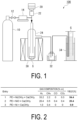
- FIG. 1 illustrates an example of an apparatus for producing a transition metal nanoparticle support of the present invention.
- an apparatus 100 for producing a transition metal nanoparticle support of the present embodiment includes a gas supply unit 10, a water supply unit 20, a reactor 24, a heating furnace 30, a cooling unit 32, and a gas collection unit 34.
- the gas supply unit 10 and the reactor 24 are connected to each other by a pipe, and the pipe is provided with an on-off valve 12 and a flowmeter 14.
- the water supply unit 20 and the reactor 24 are connected to each other by a pipe, and the pipe is provided with a water amount adjusting device 22.
- the reactor 24 is provided so as to be heated by the heating furnace 30.
- the reactor 24 and the cooling unit 32 are connected to each other by a pipe.
- the cooling unit 32 and the gas collection unit 34 are connected to each other by a pipe.
- Examples of the gas supply unit 10 include a gas cylinder and a gas tank.
- Examples of the on-off valve 12 include an open/close valve and a flow rate regulating valve.
- the flowmeter 14 is not particularly limited as long as it can measure the flow rate of a gas, and a known flowmeter can be used.
- Examples of the water supply unit 20 include a water tank and a water pipe.
- the water amount adjusting device 22 is not particularly limited as long as it can adjust the supply amount of water, and a known water amount adjusting device can be used.
- Examples of the reactor 24 include a heat-resistant glass container, a resin container, and a metal container.
- the heating furnace 30 is not particularly limited as long as it can heat the contents, and a known electric furnace or the like can be used.
- Examples of the cooling unit 32 include a cooling trap.
- Examples of the gas collection unit 34 include a glass container capable of collecting a gas by water displacement.
- a polymeric organic compound, at least one transition metal compound (for example, copper oxide or copper hydroxide, or nickel oxide or nickel hydroxide), and an oxide or hydroxide of at least one element selected from alkali metals, alkaline earth metals, aluminum, and lanthanoids are mixed to give a mixture.
- the method of mixing the polymeric organic compound, the transition metal compound, and the oxide or hydroxide of the element is not particularly limited, and these compounds may be placed in one container and mixed for an arbitrary time by an arbitrary method.
- the step (I) preferably includes a grinding operation of further grinding the obtained mixture.
- the reaction efficiency in the step (II) is further increased.
- Examples of the grinding method in the grinding operation include a grinding method using a known grinding apparatus.
- Examples of the known grinding apparatus include a rotor mill, a ball mill, and an automatic mortar.
- the particle size of the ground product after grinding is, for example, preferably from 1 to 100 ⁇ m, and more preferably from 5 to 50 ⁇ m.
- the particle size of the ground product is equal to or greater than the above-described lower limit, the ground product is easy to handle.
- the particle size of the ground product is equal to or less than the above-described upper limit, the reaction efficiency in the step (II) is further increased.
- the particle size of the ground product means a median diameter, and can be measured using, for example, a laser diffraction/scattering particle size distribution analyzer.
- the grinding time in the grinding operation is, for example, preferably from 15 to 60 minutes, and more preferably from 20 to 40 minutes.
- the grinding time is equal to or longer than the above-described lower limit, the mixture can be sufficiently ground.
- the grinding time is equal to or shorter than the above-described upper limit, the production efficiency of the transition metal nanoparticle support can be further increased.
- polymeric organic compound examples include polyolefins, polyvinyl alcohol, polyethylene glycol, and celluloses.
- polystyrene resin examples include polyethylene and polypropylene.
- examples of the cellulose include hydroxyethyl cellulose (HEC), hydroxypropyl cellulose (HPC), hydroxypropyl methyl cellulose (HPMC), sodium carboxymethyl cellulose (Na-CMC), and methyl cellulose (MC).
- the polymeric organic compound is preferably a polyolefin, and more preferably polyethylene in terms of availability.
- the number average molecular weight (Mn) of polyethylene is, for example, preferably from 5000 to 10000, more preferably from 6000 to 9000, and still more preferably from 6500 to 7700.
- the reaction efficiency in the step (II) is further increased.
- the number average molecular weight of polyethylene can be determined, for example, by gel permeation chromatography (GPC) using polystyrene as a standard substance.
- the mass average molecular weight (Mw) of polyethylene is, for example, preferably from 10000 to 50000, more preferably from 20000 to 40000, and still more preferably from 30000 to 35000.
- Mw mass average molecular weight of polyethylene
- the reaction efficiency in the step (II) is further increased.
- the mass average molecular weight of polyethylene can be determined by the same method as that for the number average molecular weight of polyethylene.
- a hydroxide of a transition metal is preferable because the dispersibility of the produced transition metal nanoparticles on the surface of the carrier can be further increased.
- the copper oxide may be either of copper(I) oxide (Cu 2 O) and copper(II) oxide (CuO).
- nickel hydroxide is preferable because the dispersibility of the formed nickel nanoparticles on the surface of the carrier can be further increased.
- the nickel oxide may be any of nickel(II) oxide (NiO), nickel(III) oxide (Ni 2 O 3 ), and nickel dioxide (NiO 2 ).
- Examples of the oxide of at least one element selected from alkali metals, alkaline earth metals, aluminum, and lanthanoids include magnesium oxide, calcium oxide, strontium oxide, aluminum oxide, lanthanum oxide, and cerium oxide.
- magnesium oxide, calcium oxide, strontium oxide, aluminum oxide, and lanthanum hydroxide are preferable, and magnesium oxide, calcium oxide, and aluminum oxide are more preferable, because a chemically stable transition metal nanoparticle support can be obtained.
- hydroxide of at least one element selected from alkali metals, alkaline earth metals, aluminum, and lanthanoids examples include lithium hydroxide, potassium hydroxide, sodium hydroxide, magnesium hydroxide, calcium hydroxide, strontium hydroxide, aluminum hydroxide, lanthanum hydroxide, and cerium hydroxide.
- magnesium hydroxide, calcium hydroxide, strontium hydroxide, aluminum hydroxide, and lanthanum hydroxide are preferable, magnesium hydroxide and calcium hydroxide are more preferable, and calcium hydroxide is still more preferable, because a chemically stable nickel nanoparticle support can be obtained.
- the mixing ratio among the polymeric organic compound, the at least one transition metal compound, and the hydroxide of at least one element selected from alkali metals, alkaline earth metals, aluminum, and lanthanoids can be defined as follows in terms of molar ratio.
- the theoretical amount of carbon in the polymeric organic compound is defined as C, the number of moles of the transition metal compound is defined as T (Ni when nickel is used), and the number of moles of the hydroxide of at least one element selected from alkali metals, alkaline earth metals, aluminum, and lanthanoids is defined as M.
- the theoretical amount of carbon in the polymeric organic compound is determined from the number of moles of carbon atoms contained in 1 mol of the polymeric organic compound.
- the ratio C:T:M is preferably from (3:1:3) to (9:1:9), more preferably from (4:1:4) to (8:1:8), and still more preferably from (5:1:5) to (7:1:7).
- a nickel nanoparticle support in which nickel nanoparticles are well dispersed can be obtained.
- the above-mentioned range is specifically as follows.
- the ratio C:T is preferably from (3:1) to (9:1), more preferably from (4:1) to (8:1), and still more preferably from (5:1) to (7:1).
- the ratio T:M is preferably from (1:3) to (1:9), more preferably from (1:4) to (1:8), and still more preferably from (1:5) to (1:7).
- the significant digits of the numerical values in the ratios are represented in single-digit numbers, and are values rounded off to the closest whole number.
- the theoretical amount of carbon in the polymeric organic compound is determined from the number of carbon atoms contained in 1 mol of the polymeric organic compound.
- the number of moles of the number of carbon atoms contained in 1 mol of polyethylene is the number of moles of the number of carbon atoms contained in 1 mol of the repeating unit of polyethylene (-CH 2 -CH 2 -) (i.e., 2 mol).
- the theoretical amount of carbon in polyethylene is the molar mass of carbon contained in the repeating unit of polyethylene (i.e., 24 g/mol).
- the theoretical amount of carbon (g/mol) in the polymeric organic compound is the molar mass of the number of carbon atoms contained in 1 mol of the repeating unit of the polymeric organic compound.
- the mixture or the ground product obtained in the step (I) is placed inside the reactor 24 of the production apparatus 100. Then, the heating furnace 30 is operated to heat the inside of the reactor 24.
- the temperature inside the reactor 24 during heating (that is, the heating temperature) is, for example, preferably from 500 to 650°C, and more preferably from 550 to 600°C.
- the heating temperature is equal to or higher than the above-described lower limit, the reaction efficiency in the step (II) is further increased.
- the heating temperature is equal to or lower than the above-described upper limit, energy consumption can be further reduced.
- the heating time is, for example, preferably from 30 to 120 minutes, more preferably from 40 to 100 minutes, and still more preferably from 50 to 80 minutes.
- the heating time is equal to or longer than the above-described lower limit, the reaction in the step (II) proceeds more reliably.
- the heating time is equal to or shorter than the above-described upper limit, the production efficiency of the transition metal nanoparticle support can be further increased.
- an inert gas such as argon (Ar) is supplied from the gas supply unit 10 into the reactor 24.
- the flow rate of the inert gas can be read from the flowmeter 14, and can be adjusted by the on-off valve 12.
- Supply of the inert gas into the reactor 24 can inhibit mixing of impurities such as oxygen into the reactor 24.
- the flow rate of the inert gas is, for example, preferably from 1 to 10 mL/min, more preferably from 2 to 8 mL/min, and still more preferably from 4 to 6 mL/min.
- the flow rate of the inert gas is equal to or greater than the above-described lower limit, it is possible to inhibit mixing of impurities into the reactor 24 more reliably.
- the flow rate of the inert gas is equal to or less than the above-described upper limit, the reaction efficiency in the step (II) is further increased.
- water is preferably supplied from the water supply unit 20 into the reactor 24 (for example, water is preferably added dropwise to the mixture inside the reactor 24).
- water supplied into the reactor 24 that is, water vapor
- hydrogen gas is obtained.
- a reaction considered to be a main reaction in which hydrogen is generated is steam reforming (Formula (1)).
- a dehydrogenation reaction proceeds, hydrogen gas is directly generated from polyethylene itself, whereas when steam reforming proceeds, there is a possibility that hydrogen gas is generated by a reaction between polyethylene and water.
- steam reforming is accompanied by a water gas shift reaction (Formula (2)) and a methanation reaction (Formula (3)), and CO generated by the steam reforming is converted into CO 2 with the generation of additional hydrogen gas by the water gas shift reaction.
- part of CO is methanated by consuming hydrogen gas.
- the amount of hydrogen gas generated is theoretically maximized when CO generated by the steam reforming entirely proceeds to the water gas shift reaction.
- the amount of hydrogen gas generated is three times the amount of hydrogen contained in the raw material polyethylene.
- the yield of the generated hydrogen gas can be calculated from Formula (4) on the assumption that the steam reforming (Formula (1)) and the water gas shift reaction (Formula (2)) proceed.
- the yield of the generated hydrogen gas is calculated from the ratio of the amount of hydrogen gas actually generated to the theoretical value calculated on the assumption that all hydrogen atoms contained in polyethylene are converted into hydrogen gas by the steam reforming and the water gas shift reaction.
- V represents the gas volume after heating and flowing of Ar
- R represents the gas constant and is 0.082
- T represents the room temperature at the time of gas collection
- M is 28 [g/mol] that corresponds to one repeating unit (-CH 2 -CH 2 -).
- the flow rate at which water is supplied into the reactor 24 can be adjusted by the water amount adjusting device 22.
- the flow rate of water supplied into the reactor 24 is, for example, preferably from 0.1 to 1.0 mL/min, more preferably from 0.2 to 0.8 mL/min, and still more preferably from 0.3 to 0.5 mL/min.
- the flow rate of water supplied into the reactor 24 is equal to or greater than the above-described lower limit, the amount of hydrogen gas to be obtained can be increased.
- the flow rate of water supplied into the reactor 24 is equal to or less than the above-described upper limit, a decrease in the temperature inside the reactor 24 can be inhibited.
- the water supplied into the reactor 24 may be pure water or tap water, but pure water is preferable from the viewpoint of inhibiting mixing of impurities into the reactor 24.
- Examples of the pure water include distilled water and ion-exchanged water.
- the above-mentioned flow rate of water is a flow rate per 2 g of the mixture introduced into the reactor 24, and is preferably adjusted in proportion to the amount of the mixture.
- the gas generated inside the reactor 24 is cooled in the cooling unit 32.
- the gas cooled in the cooling unit 32 is collected as a generated gas G in the gas collection unit 34.
- step (II) The mixture or the ground product obtained in the step (I) is heated at the above-mentioned temperature for a predetermined time to give a solid residue S (step (II)).
- transition metal nanoparticle support of the present embodiment it is not necessary to subject the surface of the transition metal nanoparticles to treatment such as oxidation prevention, and a transition metal nanoparticle support having catalytic activity can be obtained merely by performing heat treatment.
- transition metal nanoparticles can be produced more easily.
- a polymeric organic compound a polyethylene powder having a number average molecular weight of 7700 and a mass average molecular weight of 35000 was prepared.
- nickel hydroxide was prepared.
- a hydroxide or oxide of at least one element selected from alkali metals, alkaline earth metals, aluminum, and lanthanoids calcium hydroxide was prepared.
- Polyethylene, nickel hydroxide, and calcium hydroxide were mixed at a molar ratio of 6:1:6 (the molar ratio of polyethylene is the number of moles of the theoretical amount of carbon in polyethylene). The mixture was ground for 30 minutes using a planetary ball mill to give a ground product having an average particle size of 10 ⁇ m (step (I)).
- step (II) In a glass reactor (volume: 235 mL), 2 g of the ground product was placed, and the reactor was heated to 600°C with an electric furnace capable of heating the reactor (step (II)). While the reactor was heated, argon gas was supplied from a gas cylinder into the reactor at a rate of 5 mL/min. While the reactor was heated, distilled water was added dropwise from a water tank to the ground product in the reactor at a rate of 0.3 mL/min. After 60 minutes from the dropwise addition of distilled water, heating of the electric furnace was stopped, followed by air cooling. A gas generated from the reactor was cooled in a cooling trap and then collected in a glass cylinder by water displacement.
- the gas collected in the cylinder was analyzed for composition by a gas chromatograph/thermal conductivity detector (GC-TCD).
- a solid residue was collected from the cooled reactor (step (III)).
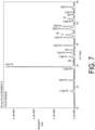
- the resulting solid residue was analyzed by powder X-ray diffraction (XRD).
- the obtained solid residue was extracted with chloroform (CHCl 3 ), and subjected to structural analysis by 1 HNMR (proton nuclear magnetic resonance).
- 1 HNMR proton nuclear magnetic resonance
- it was found that the obtained solid residue was a support in which nickel (Ni) nanoparticles were supported on calcium carbonate (CaCO 3 ).
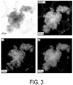
- the composition of the gas analyzed by a GC-TCD is presented in FIG. 2 (Entry 1). Images obtained by observing the obtained solid residue with a transmission electron microscope (TEM) are given in FIGS. 3 and 4 .
- TEM transmission electron microscope
- Example 1 As presented in FIG. 2 , it was found that the gas generated in Example 1 contained 33.2 vol% of hydrogen. The yield of hydrogen was 54.4% relative to the theoretical maximum value, and was a high yield of 50% or more.
- the support obtained in Example 1 was a support in which nickel nanoparticles (nanoparticles of metal nickel) were supported.
- the particle size of the nickel nanoparticles was from 5 to 50 nm, and it was found that the nickel nanoparticles were dispersed and supported on the entire carrier.
- the upper left image is a bright field photograph
- the upper right image is a photograph in which the entire support is caused to emit fluorescence
- the lower left image is a photograph in which nickel nanoparticles are caused to emit fluorescence
- the lower right image is a photograph in which the carrier is caused to emit fluorescence.
- FIG. 4 is photographs in which a part of FIG. 3 is enlarged. In FIG.
- the upper left image is a bright field photograph
- the upper right image is a photograph in which the entire support is caused to emit fluorescence
- the lower left image is a photograph in which nickel nanoparticles are caused to emit fluorescence
- the lower right image is a photograph in which the carrier is caused to emit fluorescence.
- the dark black portions indicate the presence of nickel nanoparticles, and the light black portions indicate the presence of the carrier.
- the presence of oxygen, calcium, and nickel is indicated by shading (actually by color coding).
- the lower left photographs of FIGS. 3 and 4 brightly indicate the presence of nickel.
- the lower right photographs of FIGS. 3 and 4 brightly indicate the presence of calcium.
- Example 2 A gas was generated and a solid residue was obtained in the same manner as in Example 1 except that nickel(II) oxide was used as the transition metal compound. As a result of XRD and 1 HNMR, it was found that the obtained solid residue was a support in which nickel nanoparticles were supported on calcium carbonate.
- the composition of the generated gas analyzed by a GC-TCD is presented in FIG. 2 (Entry 2).
- Example 2 As presented in FIG. 2 , it was found that the gas generated in Example 2 contained 20.4 vol% of hydrogen. The yield of hydrogen was 20.4% relative to the theoretical maximum value, and was 20% or more.
- a gas was generated and a solid residue was obtained in the same manner as in Example 1 except that metal nickel was used instead of nickel oxide or nickel hydroxide.
- metal nickel was used instead of nickel oxide or nickel hydroxide.
- FIG. 2 Entry 3
- Images obtained by observing the obtained solid residue with a transmission electron microscope (TEM) are given in FIG. 5 .
- the upper left image is a bright field photograph
- the upper right image is a photograph in which the entire support is caused to emit fluorescence
- the lower left image is a photograph in which nickel nanoparticles are caused to emit fluorescence
- the lower right image is a photograph in which the carrier is caused to emit fluorescence.
- step I Polyethylene, nickel hydroxide, and calcium hydroxide were mixed in the same manner as in Example 1 using a planetary ball mill at a rotational speed of 700 rpm for 30 minutes to give a ground product containing polyethylene (theoretical amount of carbon), nickel hydroxide, and calcium hydroxide at a molar ratio of 6:1:6 (step I).
- steps II and III were also performed in the same manner as in Example 1 to give a Ni nanoparticle support, and the analysis was performed.
- the generated gas contained 48.3 vol% of hydrogen, and the hydrogen yield was 53.4% of the theoretical maximum value.
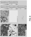
- FIG. 8 The results of elemental mapping of the solid residue obtained in step III by an EPMA (electron probe microanalyzer) are illustrated in FIG. 8 .
- the upper left and right photographs are bright field photographs taken with a SEM, the middle-left photograph indicates the presence of oxygen by shading (actually by color coding), the middle right photograph indicates the presence of calcium by shading, and the lower left photograph indicates the presence of Ni by shading. From these photographs, it was found that the Ni nanoparticles were substantially uniformly dispersed over the entire surface of the calcium oxide carrier.
- a ground product containing polyethylene (theoretical amount of carbon), nickel hydroxide, and calcium hydroxide at a molar ratio of 6:1:6 was obtained in the same manner as in Example 1 except that the components were mixed manually using a pestle and a mortar without using a planetary ball mill (step I). Subsequently, steps II and III were also performed in the same manner as in Example 1 to give a Ni nanoparticle support, and the analysis was performed. As a result, the generated gas contained 39.7 vol% of hydrogen, and the hydrogen yield was 37.5% of the theoretical maximum value. X-ray diffraction analysis was performed in the same manner as in Example 3, and the same conclusion as in Example 3 was obtained.
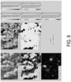
- FIG. 9 The results of elemental mapping of the solid residue obtained in step III by an EPMA are illustrated in FIG. 9 .
- the arrangement of the photographs is the same as in FIG. 8 . From these photographs, it was found that Ni nanoparticles were locally present in a small number of places on the surface of the calcium oxide carrier in a concentrated manner.
- the results of elemental mapping of the solid residue obtained in step III by an EPMA are illustrated in FIG. 12 .
- the upper left and right photographs are bright field photographs taken with a SEM, the middle-left photograph indicates the presence of oxygen by shading (actually by color coding), the middle right photograph indicates the presence of calcium by shading, and the lower left photograph indicates the presence of Cu by shading. From these photographs, it was found that the Cu nanoparticles were widely dispersed over the entire surface of the calcium oxide carrier.
- a ground product containing polyethylene (theoretical amount of carbon), copper oxide, and calcium hydroxide at a molar ratio of 5.8:1.2:5.8 was obtained in the same manner as in Example 5 except that the components were mixed manually using a pestle and a mortar without using a planetary ball mill (step I). Subsequently, steps II and III were also performed in the same manner as in Example 5 to give a Cu nanoparticle support, and the analysis was performed. As a result, the generated gas contained 1.9 vol% of hydrogen. X-ray diffraction analysis was performed in the same manner as in Example 5, and the same conclusion as in Example 5 was obtained.
- FIG. 13 The results of elemental mapping of the solid residue obtained in step III by an EPMA are illustrated in FIG. 13 .
- the arrangement of the photographs is the same as in FIG. 12 . From these photographs, it was found that Cu nanoparticles were locally present in a small number of places on the surface of the calcium oxide carrier in a concentrated manner.
- step I Polyethylene, copper hydroxide, and calcium hydroxide were mixed in the same manner as in Example 1 using a planetary ball mill at a rotational speed of 700 rpm for 30 minutes to give a ground product containing polyethylene (theoretical amount of carbon), copper hydroxide, and calcium hydroxide at a molar ratio of 6:1:6 (step I). Subsequently, steps II and III were also performed in the same manner as in Example 1 to give a Cu nanoparticle support, and the analysis was performed. As a result, the generated gas contained 7.3 vol% of hydrogen.
- Elemental mapping of the solid residue obtained in step III was performed by an EPMA (not illustrated), and it was found that Cu nanoparticles were dispersed over the entire surface of the calcium oxide carrier.
- a ground product containing polyethylene (theoretical amount of carbon), copper hydroxide, and calcium hydroxide at a molar ratio of 6:1:6 was obtained in the same manner as in Example 7 except that the components were mixed manually using a pestle and a mortar without using a planetary ball mill (step I). Subsequently, steps II and III were also performed in the same manner as in Example 7 to give a Cu nanoparticle support, and the analysis was performed. As a result, the generated gas contained 1.9 vol% of hydrogen. X-ray diffraction analysis was performed in the same manner as in Example 7, and the same conclusion as in Example 7 was obtained.
- Elemental mapping of the solid residue obtained in step III was performed by an EPMA (not illustrated), and it was found that Cu nanoparticles were locally present in a small number of places on the surface of the calcium oxide carrier in a concentrated manner.
- the transition metal nanoparticle support of the present invention can be used not only as a catalyst for hydrogenation reactions but also as a catalyst for various chemical reactions, a catalyst for fuel cells, an electrode material, and the like, and can be applied to various fields.
- the transition metal nanoparticle support of the present invention when being used as a catalyst, can be repeatedly used twice or more.
Landscapes
- Chemical & Material Sciences (AREA)
- Chemical Kinetics & Catalysis (AREA)
- Engineering & Computer Science (AREA)
- Materials Engineering (AREA)
- Organic Chemistry (AREA)
- Physics & Mathematics (AREA)
- Thermal Sciences (AREA)
- General Chemical & Material Sciences (AREA)
- Inorganic Chemistry (AREA)
- Nanotechnology (AREA)
- Catalysts (AREA)
- Manufacture Of Metal Powder And Suspensions Thereof (AREA)
Abstract
Description
- The present invention relates to a method for producing a transition metal nanoparticle support, and also to a transition metal nanoparticle support. The present application claims priority from the
Japanese Patent Application No. 2022-054850 filed in Japan on March 30, 2022 - Transition metals such as nickel and copper can be applied to various fields as a catalyst for fuel cells, a catalyst for hydrogenation reactions, or a catalyst for various chemical reactions. From the viewpoint of increasing catalytic activity, studies have been conducted to make the transition metal particles nano-sized.
- For example, Patent Document 1 proposes a method for producing nickel nanoparticles, the method including the steps of: mixing a nickel precursor, an organic amine, and a reducing agent to prepare a mixture; and mixing an organic solvent in the mixture and heating the mixture. According to the production method described in Patent Document 1, it is easy to control the size and shape of nickel nanoparticles, and nickel nanoparticles can be obtained with a high yield by a simpler process.
- Patent Document 1:
JP 2010-037647 A - However, in the production of nickel nanoparticles from a liquid phase as in the production method described in Patent Document 1, a waste liquid is produced, and the treatment of the waste liquid is required. In addition, it is necessary to subject the surface of the produced nickel nanoparticles to treatment such as oxidation prevention, and thus an extra step is added to the production of the nickel nanoparticles.
- Moreover, no example has been reported about a study of a method for producing, in the production of nickel nanoparticles, a nickel nanoparticle support in which nickel nanoparticles are supported.
- Accordingly, an object of the present invention is to provide nanoparticles of a transition metal such as nickel or copper, a support of the nanoparticles, and a method for easily producing the nanoparticles and the support in a solid phase.
- In order to solve the above-mentioned issue, the present invention has the following aspects.
- [1] A method for producing a transition metal nanoparticle support, the method including the steps of:
- (I) obtaining a mixture by mixing a polymeric organic compound, an oxide of at least one transition metal or a hydroxide of at least one transition metal, and an oxide or hydroxide of at least one element selected from alkali metals, alkaline earth metals, aluminum, and lanthanoids;
- (II) obtaining a solid residue by heating the mixture; and
- (III) obtaining, from the solid residue, a support in which nanoparticles of the at least one transition metal are supported.
- [2] The method for producing a transition metal nanoparticle support according to [1], wherein the element is at least one selected from alkali metals and alkaline earth metals.
- [3] The method for producing a transition metal nanoparticle support according to [1] or [2], wherein the polymeric organic compound is at least one selected from polyolefins, polyvinyl alcohol, polyethylene glycol, and celluloses.
- [4] The method for producing a transition metal nanoparticle support according to any one of [1] to [3], wherein the step (I) includes a grinding operation of grinding the mixture.
- [5] The method for producing a transition metal nanoparticle support according to any one of [1] to [4], wherein a heating temperature in the step (II) is from 500 to 650°C.
- [6] The method for producing a transition metal nanoparticle support according to any one of [1] to [5], wherein in the step (II), water is added dropwise to the mixture.
- [7] The method for producing a transition metal nanoparticle support according to any one of [1] to [6], wherein the transition metal is copper or nickel.
- [8] A nickel nanoparticle support containing:
- a carrier containing at least one element selected from alkali metals, alkaline earth metals, aluminum, and lanthanoids; and
- transition metal nanoparticles supported on the carrier.
- According to the method for producing a transition metal nanoparticle support of the present invention, transition metal nanoparticles can be produced more easily.
-
-
FIG. 1 is a schematic view illustrating an example of an apparatus for producing a transition metal nanoparticle support of the present invention. -
FIG. 2 is a table indicating results of a steam reforming reaction in which nickel nanoparticle supports according to an embodiment of the present invention were used. -
FIG. 3 is an example of transmission electron microscope (TEM) photographs of a nickel nanoparticle support according to an embodiment of the present invention. -
FIG. 4 is photographs in which a part ofFIG. 3 is enlarged. -
FIG. 5 is an example of transmission electron microscope (TEM) photographs of a nickel particle support according to a comparative example. -
FIG. 6 is an X-ray diffraction spectrum of a ground product before heating used in the production of Example 3. -
FIG. 7 is an X-ray diffraction spectrum of a nickel nanoparticle support produced in Example 3. -
FIG. 8 illustrates measurement results of the nickel nanoparticle support produced in Example 3 by an electron probe microanalyzer. -
FIG. 9 illustrates measurement results of a nickel nanoparticle support produced in Example 4 by an electron probe microanalyzer. -
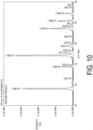
FIG. 10 is an X-ray diffraction spectrum of a ground product before heating used in the production of Example 5. -
FIG. 11 illustrates measurement results of a copper nanoparticle support produced in Example 5 by an electron probe microanalyzer. -
FIG. 12 illustrates measurement results of the copper nanoparticle support produced in Example 5 by an electron probe microanalyzer. -
FIG. 13 illustrates measurement results of a copper nanoparticle support produced in Example 6 by an electron probe microanalyzer. - A transition metal nanoparticle support according to a first aspect of the present invention contains a carrier containing at least one element selected from alkali metals, alkaline earth metals, aluminum, and lanthanoids, and nanoparticles of at least one transition metal that are supported on the carrier. At least a part of the supported transition metal is preferably an unoxidized pure metal. In other words, a part of the supported transition metal may be oxidized by contact with air.
- Here, the word "transition metal nanoparticles" refers to particles formed of a transition metal and having a particle size on the order of nanometers. The particle size of the transition metal nanoparticles is determined by observation using a transmission electron microscope (TEM).
- The type of the transition metal forming the transition metal nanoparticles is not particularly limited, and examples thereof include copper (Cu), nickel (Ni), cobalt (Co), iron (Fe), manganese (Mn), chromium (Cr), vanadium (V), titanium (Ti), and scandium (Sc). Among them, copper and nickel useful as catalysts for various chemical reactions are preferable.
- In the following, nanoparticles formed of copper may be referred to as copper nanoparticles, and nanoparticles formed of nickel may be referred to as nickel nanoparticles.
- In the following, nanoparticles of transition metals, such as nickel nanoparticles and copper nanoparticles, are collectively referred to as transition metal nanoparticles. Hereinafter, a preferred embodiment of the transition metal nanoparticles is described.
- The particle size of the transition metal nanoparticles is, for example, preferably from 0.1 to 100 nm, more preferably from 0.5 to 50 nm, and still more preferably from 1 to 30 nm. When the particle size of the transition metal nanoparticles is equal to or greater than the above-described lower limit, the transition metal nanoparticle support has higher catalytic activity when being used as a catalyst. When the particle size of the transition metal nanoparticles is equal to or less than the above-described upper limit, the dispersibility of the nickel nanoparticles can be further increased, and as a result, the transition metal nanoparticle support has higher catalytic activity when being used as a catalyst.
- Here, the particle size of the transition metal nanoparticles can be determined by observation using a TEM, and the longest length of the transition metal nanoparticles on a TEM image is defined as the particle size of the transition metal nanoparticles.
- The shape of the transition metal nanoparticle support is not particularly limited, and is preferably a particle shape from the viewpoint of increasing the surface area as a catalyst. A plurality of transition metal nanoparticles is exposed at least partially, preferably entirely on the surface of the carrier.
- The particle size of the transition metal nanoparticle support is, for example, preferably from 0.5 to 100 µm, more preferably from 1 to 50 µm, and still more preferably from 3 to 30 µm. When the particle size of the transition metal nanoparticle support is equal to or greater than the above-described lower limit, a larger amount of transition metal nanoparticles can be supported. When the particle size of the transition metal nanoparticle support is equal to or less than the above-described upper limit, the strength of the transition metal nanoparticle support can be further increased.
- Here, the particle size of the transition metal nanoparticle support can be determined by observation using a TEM, and the longest length of the transition metal nanoparticle support on a TEM image is defined as the particle size of the transition metal nanoparticle support.
- The shape and particle size of the transition metal nanoparticle support are largely determined by the shape and particle size of the carrier.
- Examples of the carrier of the transition metal nanoparticle support include compounds containing at least one element selected from alkali metals, alkaline earth metals, aluminum, and lanthanoids.
- Examples of the alkali metals include lithium (Li), sodium (Na), potassium (K), rubidium (Rb), cesium (Cs), and francium (Fr).
- Examples of the alkaline earth metals include beryllium (Be), magnesium (Mg), calcium (Ca), strontium (Sr), barium (Ba), and radium (Ra).
- Examples of the lanthanoids include lanthanum (La), cerium (Ce), praseodymium (Pr), neodymium (Nd), europium (Eu), ytterbium (Yb), and lutetium (Lu).
- Examples of the compound that constitutes the carrier of the nickel nanoparticle support include carbonates, phosphates, hydrochlorides, and sulfates of the above-mentioned elements. Among these compounds, carbonates and phosphates are preferable, and carbonates are more preferable, because the transition metal nanoparticles are easily supported on the carrier.
- Among the above-mentioned elements, alkali metals and alkaline earth metals are preferable, alkaline earth metals are more preferable, magnesium and calcium are still more preferable, and calcium is particularly preferable in terms of availability.
- As for the carrier of the transition metal nanoparticle support, one type may be used alone, or two or more types may be used in combination.
- A method for producing a transition metal nanoparticle support according to a second aspect of the present invention includes the steps of: (I) obtaining a mixture by mixing a polymeric organic compound, an oxide of at least one transition metal or a hydroxide of at least one transition metal (hereinafter, the oxide and the hydroxide may be collectively referred to as transition metal compounds), and an oxide or hydroxide of at least one element selected from alkali metals, alkaline earth metals, aluminum, and lanthanoids; (II) obtaining a solid residue by heating the mixture; and (III) obtaining, from the solid residue, a support in which nanoparticles of the at least one transition metal are supported.
- The transition metal nanoparticle support of the first aspect can be produced by the production method of the present aspect.
- Hereinafter, an embodiment of the method for producing a transition metal nanoparticle support of the present invention is described in detail with reference to the drawings. Steps from (I) to (III) of the present aspect are not limited to the examples in the following embodiment, and various modifications can be made within the scope of the gist of the present invention. The phrase "step of obtaining..." in the present aspect may be rephrased as "obtaining...".
-
FIG. 1 illustrates an example of an apparatus for producing a transition metal nanoparticle support of the present invention. - As illustrated in
FIG. 1 , anapparatus 100 for producing a transition metal nanoparticle support of the present embodiment includes agas supply unit 10, awater supply unit 20, areactor 24, aheating furnace 30, a coolingunit 32, and agas collection unit 34. Thegas supply unit 10 and thereactor 24 are connected to each other by a pipe, and the pipe is provided with an on-offvalve 12 and aflowmeter 14. Thewater supply unit 20 and thereactor 24 are connected to each other by a pipe, and the pipe is provided with a wateramount adjusting device 22. Thereactor 24 is provided so as to be heated by theheating furnace 30. Thereactor 24 and thecooling unit 32 are connected to each other by a pipe. The coolingunit 32 and thegas collection unit 34 are connected to each other by a pipe. - Examples of the
gas supply unit 10 include a gas cylinder and a gas tank. - Examples of the on-off
valve 12 include an open/close valve and a flow rate regulating valve. - The
flowmeter 14 is not particularly limited as long as it can measure the flow rate of a gas, and a known flowmeter can be used. - Examples of the
water supply unit 20 include a water tank and a water pipe. - The water
amount adjusting device 22 is not particularly limited as long as it can adjust the supply amount of water, and a known water amount adjusting device can be used. - Examples of the
reactor 24 include a heat-resistant glass container, a resin container, and a metal container. - The
heating furnace 30 is not particularly limited as long as it can heat the contents, and a known electric furnace or the like can be used. - Examples of the cooling
unit 32 include a cooling trap. - Examples of the
gas collection unit 34 include a glass container capable of collecting a gas by water displacement. - In the step (I), a polymeric organic compound, at least one transition metal compound (for example, copper oxide or copper hydroxide, or nickel oxide or nickel hydroxide), and an oxide or hydroxide of at least one element selected from alkali metals, alkaline earth metals, aluminum, and lanthanoids are mixed to give a mixture. The method of mixing the polymeric organic compound, the transition metal compound, and the oxide or hydroxide of the element is not particularly limited, and these compounds may be placed in one container and mixed for an arbitrary time by an arbitrary method.
- The step (I) preferably includes a grinding operation of further grinding the obtained mixture. When the mixture is ground, the reaction efficiency in the step (II) is further increased.
- Examples of the grinding method in the grinding operation include a grinding method using a known grinding apparatus. Examples of the known grinding apparatus include a rotor mill, a ball mill, and an automatic mortar.
- The particle size of the ground product after grinding is, for example, preferably from 1 to 100 µm, and more preferably from 5 to 50 µm. When the particle size of the ground product is equal to or greater than the above-described lower limit, the ground product is easy to handle. When the particle size of the ground product is equal to or less than the above-described upper limit, the reaction efficiency in the step (II) is further increased.
- The particle size of the ground product means a median diameter, and can be measured using, for example, a laser diffraction/scattering particle size distribution analyzer.
- The grinding time in the grinding operation is, for example, preferably from 15 to 60 minutes, and more preferably from 20 to 40 minutes. When the grinding time is equal to or longer than the above-described lower limit, the mixture can be sufficiently ground. When the grinding time is equal to or shorter than the above-described upper limit, the production efficiency of the transition metal nanoparticle support can be further increased.
- Examples of the polymeric organic compound include polyolefins, polyvinyl alcohol, polyethylene glycol, and celluloses.
- Examples of the polyolefin include polyethylene and polypropylene. Examples of the cellulose include hydroxyethyl cellulose (HEC), hydroxypropyl cellulose (HPC), hydroxypropyl methyl cellulose (HPMC), sodium carboxymethyl cellulose (Na-CMC), and methyl cellulose (MC). The polymeric organic compound is preferably a polyolefin, and more preferably polyethylene in terms of availability.
- The number average molecular weight (Mn) of polyethylene is, for example, preferably from 5000 to 10000, more preferably from 6000 to 9000, and still more preferably from 6500 to 7700. When the number average molecular weight of polyethylene is within the above-mentioned numerical range, the reaction efficiency in the step (II) is further increased.
- The number average molecular weight of polyethylene can be determined, for example, by gel permeation chromatography (GPC) using polystyrene as a standard substance.
- The mass average molecular weight (Mw) of polyethylene is, for example, preferably from 10000 to 50000, more preferably from 20000 to 40000, and still more preferably from 30000 to 35000. When the mass average molecular weight of polyethylene is within the above-mentioned numerical range, the reaction efficiency in the step (II) is further increased.
- The mass average molecular weight of polyethylene can be determined by the same method as that for the number average molecular weight of polyethylene.
- When an oxide of a transition metal and a hydroxide of a transition metal used as materials are compared with each other, a hydroxide of a transition metal is preferable because the dispersibility of the produced transition metal nanoparticles on the surface of the carrier can be further increased.
- When copper oxide and copper hydroxide used as materials are compared with each other, copper hydroxide is preferable because the dispersibility of the produced copper nanoparticles on the surface of the carrier can be further increased. The copper oxide may be either of copper(I) oxide (Cu2O) and copper(II) oxide (CuO).
- When nickel oxide and nickel hydroxide used as materials are compared with each other, nickel hydroxide is preferable because the dispersibility of the formed nickel nanoparticles on the surface of the carrier can be further increased. The nickel oxide may be any of nickel(II) oxide (NiO), nickel(III) oxide (Ni2O3), and nickel dioxide (NiO2).
- Examples of the oxide of at least one element selected from alkali metals, alkaline earth metals, aluminum, and lanthanoids include magnesium oxide, calcium oxide, strontium oxide, aluminum oxide, lanthanum oxide, and cerium oxide. Among these oxides, magnesium oxide, calcium oxide, strontium oxide, aluminum oxide, and lanthanum hydroxide are preferable, and magnesium oxide, calcium oxide, and aluminum oxide are more preferable, because a chemically stable transition metal nanoparticle support can be obtained.
- Examples of the hydroxide of at least one element selected from alkali metals, alkaline earth metals, aluminum, and lanthanoids include lithium hydroxide, potassium hydroxide, sodium hydroxide, magnesium hydroxide, calcium hydroxide, strontium hydroxide, aluminum hydroxide, lanthanum hydroxide, and cerium hydroxide. Among these hydroxides, magnesium hydroxide, calcium hydroxide, strontium hydroxide, aluminum hydroxide, and lanthanum hydroxide are preferable, magnesium hydroxide and calcium hydroxide are more preferable, and calcium hydroxide is still more preferable, because a chemically stable nickel nanoparticle support can be obtained.
- The mixing ratio among the polymeric organic compound, the at least one transition metal compound, and the hydroxide of at least one element selected from alkali metals, alkaline earth metals, aluminum, and lanthanoids can be defined as follows in terms of molar ratio.
- The theoretical amount of carbon in the polymeric organic compound is defined as C, the number of moles of the transition metal compound is defined as T (Ni when nickel is used), and the number of moles of the hydroxide of at least one element selected from alkali metals, alkaline earth metals, aluminum, and lanthanoids is defined as M. The theoretical amount of carbon in the polymeric organic compound is determined from the number of moles of carbon atoms contained in 1 mol of the polymeric organic compound.
- The ratio C:T:M is preferably from (3:1:3) to (9:1:9), more preferably from (4:1:4) to (8:1:8), and still more preferably from (5:1:5) to (7:1:7). When the compounds are mixed so that the ratio C:T:M is within the above-mentioned numerical range, a nickel nanoparticle support in which nickel nanoparticles are well dispersed can be obtained.
- The above-mentioned range is specifically as follows. The ratio C:T is preferably from (3:1) to (9:1), more preferably from (4:1) to (8:1), and still more preferably from (5:1) to (7:1). The ratio T:M is preferably from (1:3) to (1:9), more preferably from (1:4) to (1:8), and still more preferably from (1:5) to (1:7). Here, the significant digits of the numerical values in the ratios are represented in single-digit numbers, and are values rounded off to the closest whole number.
- The theoretical amount of carbon in the polymeric organic compound is determined from the number of carbon atoms contained in 1 mol of the polymeric organic compound. Specifically, for example, the number of moles of the number of carbon atoms contained in 1 mol of polyethylene is the number of moles of the number of carbon atoms contained in 1 mol of the repeating unit of polyethylene (-CH2-CH2-) (i.e., 2 mol). The theoretical amount of carbon in polyethylene is the molar mass of carbon contained in the repeating unit of polyethylene (i.e., 24 g/mol). In general, the theoretical amount of carbon (g/mol) in the polymeric organic compound is the molar mass of the number of carbon atoms contained in 1 mol of the repeating unit of the polymeric organic compound.
- The mixture or the ground product obtained in the step (I) is placed inside the
reactor 24 of theproduction apparatus 100. Then, theheating furnace 30 is operated to heat the inside of thereactor 24. - The temperature inside the
reactor 24 during heating (that is, the heating temperature) is, for example, preferably from 500 to 650°C, and more preferably from 550 to 600°C. When the heating temperature is equal to or higher than the above-described lower limit, the reaction efficiency in the step (II) is further increased. When the heating temperature is equal to or lower than the above-described upper limit, energy consumption can be further reduced. - The heating time is, for example, preferably from 30 to 120 minutes, more preferably from 40 to 100 minutes, and still more preferably from 50 to 80 minutes. When the heating time is equal to or longer than the above-described lower limit, the reaction in the step (II) proceeds more reliably. When the heating time is equal to or shorter than the above-described upper limit, the production efficiency of the transition metal nanoparticle support can be further increased.
- At the time of heating the inside of the
reactor 24, an inert gas such as argon (Ar) is supplied from thegas supply unit 10 into thereactor 24. The flow rate of the inert gas can be read from theflowmeter 14, and can be adjusted by the on-offvalve 12. Supply of the inert gas into thereactor 24 can inhibit mixing of impurities such as oxygen into thereactor 24. - The flow rate of the inert gas is, for example, preferably from 1 to 10 mL/min, more preferably from 2 to 8 mL/min, and still more preferably from 4 to 6 mL/min. When the flow rate of the inert gas is equal to or greater than the above-described lower limit, it is possible to inhibit mixing of impurities into the
reactor 24 more reliably. When the flow rate of the inert gas is equal to or less than the above-described upper limit, the reaction efficiency in the step (II) is further increased. - At the time of heating the inside of the
reactor 24, water is preferably supplied from thewater supply unit 20 into the reactor 24 (for example, water is preferably added dropwise to the mixture inside the reactor 24). When water is supplied into thereactor 24, the water supplied into the reactor 24 (that is, water vapor) is reformed into hydrogen by the catalytic action of the transition metal, and hydrogen gas is obtained. - When polyethylene is used as the polymeric organic compound, a reaction considered to be a main reaction in which hydrogen is generated is steam reforming (Formula (1)). When a dehydrogenation reaction proceeds, hydrogen gas is directly generated from polyethylene itself, whereas when steam reforming proceeds, there is a possibility that hydrogen gas is generated by a reaction between polyethylene and water. In addition, it is known that steam reforming is accompanied by a water gas shift reaction (Formula (2)) and a methanation reaction (Formula (3)), and CO generated by the steam reforming is converted into CO2 with the generation of additional hydrogen gas by the water gas shift reaction. In addition, part of CO is methanated by consuming hydrogen gas.
- [Chem. 1]
CnH2n + nH2O → nCO + 2nH2 (1)
nC0 + nH2O ⇄ nCO2 + nH2 (2)
nC0 + 3nH2 ⇄ nCH4 + nH2O (3)
- In the hydrogen generation by the above-mentioned reaction, the amount of hydrogen gas generated is theoretically maximized when CO generated by the steam reforming entirely proceeds to the water gas shift reaction. In this case, the amount of hydrogen gas generated is three times the amount of hydrogen contained in the raw material polyethylene.
- The yield of the generated hydrogen gas can be calculated from Formula (4) on the assumption that the steam reforming (Formula (1)) and the water gas shift reaction (Formula (2)) proceed. The yield of the generated hydrogen gas is calculated from the ratio of the amount of hydrogen gas actually generated to the theoretical value calculated on the assumption that all hydrogen atoms contained in polyethylene are converted into hydrogen gas by the steam reforming and the water gas shift reaction.
- [Math. 1]
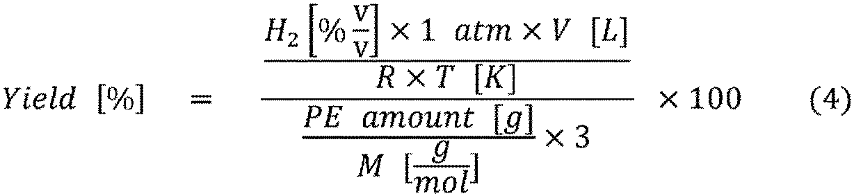
- In Formula (4), V represents the gas volume after heating and flowing of Ar, R represents the gas constant and is 0.082, T represents the room temperature at the time of gas collection, and M is 28 [g/mol] that corresponds to one repeating unit (-CH2-CH2-).
- The flow rate at which water is supplied into the
reactor 24 can be adjusted by the wateramount adjusting device 22. - The flow rate of water supplied into the
reactor 24 is, for example, preferably from 0.1 to 1.0 mL/min, more preferably from 0.2 to 0.8 mL/min, and still more preferably from 0.3 to 0.5 mL/min. When the flow rate of water supplied into thereactor 24 is equal to or greater than the above-described lower limit, the amount of hydrogen gas to be obtained can be increased. When the flow rate of water supplied into thereactor 24 is equal to or less than the above-described upper limit, a decrease in the temperature inside thereactor 24 can be inhibited. - The water supplied into the
reactor 24 may be pure water or tap water, but pure water is preferable from the viewpoint of inhibiting mixing of impurities into thereactor 24. Examples of the pure water include distilled water and ion-exchanged water. The above-mentioned flow rate of water is a flow rate per 2 g of the mixture introduced into thereactor 24, and is preferably adjusted in proportion to the amount of the mixture. - The gas generated inside the
reactor 24 is cooled in thecooling unit 32. The gas cooled in thecooling unit 32 is collected as a generated gas G in thegas collection unit 34. - The mixture or the ground product obtained in the step (I) is heated at the above-mentioned temperature for a predetermined time to give a solid residue S (step (II)).
- Heating by the
heating furnace 30 is stopped, and after thereactor 24 is cooled for a predetermined time, the solid residue S is taken out from the inside of thereactor 24. When the solid residue S is taken out from the inside of thereactor 24, a transition metal nanoparticle support in which transition metal nanoparticles are supported is obtained (step (III)). - As described above, in the method for producing a transition metal nanoparticle support of the present embodiment, since the reaction is performed not in a liquid phase but in a solid phase, no waste liquid is generated unlike in the known method for producing transition metal nanoparticles. Therefore, treatment of the waste liquid is unnecessary.
- In addition, in the method for producing a transition metal nanoparticle support of the present embodiment, it is not necessary to subject the surface of the transition metal nanoparticles to treatment such as oxidation prevention, and a transition metal nanoparticle support having catalytic activity can be obtained merely by performing heat treatment.
- Therefore, the transition metal nanoparticles can be produced more easily.
- Hereinafter, the present invention is described more specifically with reference to examples, but the present invention is not limited to these examples.
- As a polymeric organic compound, a polyethylene powder having a number average molecular weight of 7700 and a mass average molecular weight of 35000 was prepared. As a transition metal compound, nickel hydroxide was prepared. As a hydroxide or oxide of at least one element selected from alkali metals, alkaline earth metals, aluminum, and lanthanoids, calcium hydroxide was prepared. Polyethylene, nickel hydroxide, and calcium hydroxide were mixed at a molar ratio of 6:1:6 (the molar ratio of polyethylene is the number of moles of the theoretical amount of carbon in polyethylene). The mixture was ground for 30 minutes using a planetary ball mill to give a ground product having an average particle size of 10 µm (step (I)). In a glass reactor (volume: 235 mL), 2 g of the ground product was placed, and the reactor was heated to 600°C with an electric furnace capable of heating the reactor (step (II)). While the reactor was heated, argon gas was supplied from a gas cylinder into the reactor at a rate of 5 mL/min. While the reactor was heated, distilled water was added dropwise from a water tank to the ground product in the reactor at a rate of 0.3 mL/min. After 60 minutes from the dropwise addition of distilled water, heating of the electric furnace was stopped, followed by air cooling. A gas generated from the reactor was cooled in a cooling trap and then collected in a glass cylinder by water displacement. The gas collected in the cylinder was analyzed for composition by a gas chromatograph/thermal conductivity detector (GC-TCD). A solid residue was collected from the cooled reactor (step (III)). The resulting solid residue was analyzed by powder X-ray diffraction (XRD). In addition, the obtained solid residue was extracted with chloroform (CHCl3), and subjected to structural analysis by 1HNMR (proton nuclear magnetic resonance). As a result of XRD and 1HNMR, it was found that the obtained solid residue was a support in which nickel (Ni) nanoparticles were supported on calcium carbonate (CaCO3). The composition of the gas analyzed by a GC-TCD is presented in
FIG. 2 (Entry 1). Images obtained by observing the obtained solid residue with a transmission electron microscope (TEM) are given inFIGS. 3 and4 . - As presented in
FIG. 2 , it was found that the gas generated in Example 1 contained 33.2 vol% of hydrogen. The yield of hydrogen was 54.4% relative to the theoretical maximum value, and was a high yield of 50% or more. - As illustrated in
FIGS. 3 and4 , the support obtained in Example 1 was a support in which nickel nanoparticles (nanoparticles of metal nickel) were supported. The particle size of the nickel nanoparticles was from 5 to 50 nm, and it was found that the nickel nanoparticles were dispersed and supported on the entire carrier. InFIG. 3 , the upper left image is a bright field photograph, the upper right image is a photograph in which the entire support is caused to emit fluorescence, the lower left image is a photograph in which nickel nanoparticles are caused to emit fluorescence, and the lower right image is a photograph in which the carrier is caused to emit fluorescence.FIG. 4 is photographs in which a part ofFIG. 3 is enlarged. InFIG. 4 , the upper left image is a bright field photograph, the upper right image is a photograph in which the entire support is caused to emit fluorescence, the lower left image is a photograph in which nickel nanoparticles are caused to emit fluorescence, and the lower right image is a photograph in which the carrier is caused to emit fluorescence. - In the bright field photographs of
FIGS. 3 and4 , the dark black portions indicate the presence of nickel nanoparticles, and the light black portions indicate the presence of the carrier. In the upper right photographs ofFIGS. 3 and4 , the presence of oxygen, calcium, and nickel is indicated by shading (actually by color coding). The lower left photographs ofFIGS. 3 and4 brightly indicate the presence of nickel. The lower right photographs ofFIGS. 3 and4 brightly indicate the presence of calcium. - A gas was generated and a solid residue was obtained in the same manner as in Example 1 except that nickel(II) oxide was used as the transition metal compound. As a result of XRD and 1HNMR, it was found that the obtained solid residue was a support in which nickel nanoparticles were supported on calcium carbonate. The composition of the generated gas analyzed by a GC-TCD is presented in
FIG. 2 (Entry 2). - As presented in
FIG. 2 , it was found that the gas generated in Example 2 contained 20.4 vol% of hydrogen. The yield of hydrogen was 20.4% relative to the theoretical maximum value, and was 20% or more. - A gas was generated and a solid residue was obtained in the same manner as in Example 1 except that metal nickel was used instead of nickel oxide or nickel hydroxide. As a result of XRD and 1HNMR, it was found that the obtained solid residue was a support in which nickel particles were supported on calcium carbonate. The composition of the generated gas analyzed by a GC-TCD is presented in
FIG. 2 (Entry 3). Images obtained by observing the obtained solid residue with a transmission electron microscope (TEM) are given inFIG. 5 . - As illustrated in the lower left photograph of
FIG. 5 , in the support obtained in Comparative Example 1, one nickel particle having a particle size of several hundred nanometers was supported. This is considered to be because the nickel nanoparticles were aggregated to increase the particle size. InFIG. 5 , the upper left image is a bright field photograph, the upper right image is a photograph in which the entire support is caused to emit fluorescence, the lower left image is a photograph in which nickel nanoparticles are caused to emit fluorescence, and the lower right image is a photograph in which the carrier is caused to emit fluorescence. - In addition, as presented in
FIG. 2 , it was found that the gas generated in Comparative Example 1 contained only 1.0 vol% of hydrogen, and that the metal nickel hardly exhibited catalytic activity in the steam reforming reaction. - Polyethylene, nickel hydroxide, and calcium hydroxide were mixed in the same manner as in Example 1 using a planetary ball mill at a rotational speed of 700 rpm for 30 minutes to give a ground product containing polyethylene (theoretical amount of carbon), nickel hydroxide, and calcium hydroxide at a molar ratio of 6:1:6 (step I). Subsequently, steps II and III were also performed in the same manner as in Example 1 to give a Ni nanoparticle support, and the analysis was performed. As a result, the generated gas contained 48.3 vol% of hydrogen, and the hydrogen yield was 53.4% of the theoretical maximum value.
- When X-ray diffraction spectra were measured for the ground product obtained in step I and the solid residue obtained in step III, a peak derived from metal nickel was not observed in the ground product (
FIG. 6 ), and was observed only in the solid residue (FIG. 7 ). This result indicates that at least a part of the Ni nanoparticles contained in the solid residue (Ni nanoparticle support) obtained in step III are metal nickel nanoparticles. - The results of elemental mapping of the solid residue obtained in step III by an EPMA (electron probe microanalyzer) are illustrated in
FIG. 8 . The upper left and right photographs are bright field photographs taken with a SEM, the middle-left photograph indicates the presence of oxygen by shading (actually by color coding), the middle right photograph indicates the presence of calcium by shading, and the lower left photograph indicates the presence of Ni by shading. From these photographs, it was found that the Ni nanoparticles were substantially uniformly dispersed over the entire surface of the calcium oxide carrier. - A ground product containing polyethylene (theoretical amount of carbon), nickel hydroxide, and calcium hydroxide at a molar ratio of 6:1:6 was obtained in the same manner as in Example 1 except that the components were mixed manually using a pestle and a mortar without using a planetary ball mill (step I). Subsequently, steps II and III were also performed in the same manner as in Example 1 to give a Ni nanoparticle support, and the analysis was performed. As a result, the generated gas contained 39.7 vol% of hydrogen, and the hydrogen yield was 37.5% of the theoretical maximum value. X-ray diffraction analysis was performed in the same manner as in Example 3, and the same conclusion as in Example 3 was obtained.
- The results of elemental mapping of the solid residue obtained in step III by an EPMA are illustrated in
FIG. 9 . The arrangement of the photographs is the same as inFIG. 8 . From these photographs, it was found that Ni nanoparticles were locally present in a small number of places on the surface of the calcium oxide carrier in a concentrated manner. - Mixing was conducted in the same manner as in Example 1 using a planetary ball mill at a rotational speed of 700 rpm for 30 minutes to give a ground product containing polyethylene (theoretical amount of carbon), copper oxide, and calcium hydroxide at a molar ratio of 5.8:1.2:5.8 (step I). Subsequently, steps II and III were also performed in the same manner as in Example 1 to give a Cu nanoparticle support, and the analysis was performed. As a result, the generated gas contained 7.6 vol% of hydrogen. When X-ray diffraction spectra were measured for the ground product obtained in step I and the solid residue obtained in step III, a peak derived from metal copper was not observed in the ground product (
FIG. 10 ), and was observed only in the solid residue (FIG. 11 ). This result indicates that at least a part of the Cu nanoparticles contained in the solid residue (Cu nanoparticle support) obtained in step III are metal copper nanoparticles. - The results of elemental mapping of the solid residue obtained in step III by an EPMA are illustrated in
FIG. 12 . The upper left and right photographs are bright field photographs taken with a SEM, the middle-left photograph indicates the presence of oxygen by shading (actually by color coding), the middle right photograph indicates the presence of calcium by shading, and the lower left photograph indicates the presence of Cu by shading. From these photographs, it was found that the Cu nanoparticles were widely dispersed over the entire surface of the calcium oxide carrier. - A ground product containing polyethylene (theoretical amount of carbon), copper oxide, and calcium hydroxide at a molar ratio of 5.8:1.2:5.8 was obtained in the same manner as in Example 5 except that the components were mixed manually using a pestle and a mortar without using a planetary ball mill (step I). Subsequently, steps II and III were also performed in the same manner as in Example 5 to give a Cu nanoparticle support, and the analysis was performed. As a result, the generated gas contained 1.9 vol% of hydrogen. X-ray diffraction analysis was performed in the same manner as in Example 5, and the same conclusion as in Example 5 was obtained.
- The results of elemental mapping of the solid residue obtained in step III by an EPMA are illustrated in
FIG. 13 . The arrangement of the photographs is the same as inFIG. 12 . From these photographs, it was found that Cu nanoparticles were locally present in a small number of places on the surface of the calcium oxide carrier in a concentrated manner. - Polyethylene, copper hydroxide, and calcium hydroxide were mixed in the same manner as in Example 1 using a planetary ball mill at a rotational speed of 700 rpm for 30 minutes to give a ground product containing polyethylene (theoretical amount of carbon), copper hydroxide, and calcium hydroxide at a molar ratio of 6:1:6 (step I). Subsequently, steps II and III were also performed in the same manner as in Example 1 to give a Cu nanoparticle support, and the analysis was performed. As a result, the generated gas contained 7.3 vol% of hydrogen. When X-ray diffraction spectra were measured for the ground product obtained in step I and the solid residue obtained in step III, a peak derived from metal copper was not observed in the ground product (not illustrated), and was observed only in the solid residue (not illustrated). This result indicates that at least a part of the Cu nanoparticles contained in the solid residue (Cu nanoparticle support) obtained in step III are metal copper nanoparticles.
- Elemental mapping of the solid residue obtained in step III was performed by an EPMA (not illustrated), and it was found that Cu nanoparticles were dispersed over the entire surface of the calcium oxide carrier.
- A ground product containing polyethylene (theoretical amount of carbon), copper hydroxide, and calcium hydroxide at a molar ratio of 6:1:6 was obtained in the same manner as in Example 7 except that the components were mixed manually using a pestle and a mortar without using a planetary ball mill (step I). Subsequently, steps II and III were also performed in the same manner as in Example 7 to give a Cu nanoparticle support, and the analysis was performed. As a result, the generated gas contained 1.9 vol% of hydrogen. X-ray diffraction analysis was performed in the same manner as in Example 7, and the same conclusion as in Example 7 was obtained.
- Elemental mapping of the solid residue obtained in step III was performed by an EPMA (not illustrated), and it was found that Cu nanoparticles were locally present in a small number of places on the surface of the calcium oxide carrier in a concentrated manner.
- The transition metal nanoparticle support of the present invention can be used not only as a catalyst for hydrogenation reactions but also as a catalyst for various chemical reactions, a catalyst for fuel cells, an electrode material, and the like, and can be applied to various fields. The transition metal nanoparticle support of the present invention, when being used as a catalyst, can be repeatedly used twice or more.
- 10: Gas supply unit, 12: On-off valve, 14: Flowmeter, 20: Water supply unit, 22: Water amount adjusting device, 24: Reactor, 30: Heating furnace, 32: Cooling unit, 34: Gas collection unit, 100: Production apparatus, G: Generated gas, S: Solid residue
Claims (8)
- A method for producing a transition metal nanoparticle support, the method comprising the steps of:(I) obtaining a mixture by mixing: a polymeric organic compound; an oxide of at least one transition metal or a hydroxide of at least one transition metal; and an oxide or hydroxide of at least one element selected from alkali metals, alkaline earth metals, aluminum, and lanthanoids;(II) obtaining a solid residue by heating the mixture; and(III) obtaining, from the solid residue, a support in which nanoparticles of the at least one transition metal are supported.
- The method for producing a transition metal nanoparticle support according to claim 1, wherein the element is at least one selected from alkali metals and alkaline earth metals.
- The method for producing a transition metal nanoparticle support according to claim 1, wherein the polymeric organic compound is at least one selected from polyolefins, polyvinyl alcohol, polyethylene glycol, and celluloses.
- The method for producing a transition metal nanoparticle support according to claim 1, wherein the step (I) comprises a grinding operation of grinding the mixture.
- The method for producing a transition metal nanoparticle support according to claim 1, wherein a heating temperature in the step (II) is from 500 to 650°C.
- The method for producing a transition metal nanoparticle support according to claim 1, wherein in the step (II), water is added dropwise to the mixture.
- The method for producing a transition metal nanoparticle support according to claim 1, wherein the transition metal is copper or nickel.
- A transition metal nanoparticle support comprising:a carrier containing at least one element selected from alkali metals, alkaline earth metals, aluminum, and lanthanoids; andnanoparticles of at least one transition metal that are supported on the carrier.
Applications Claiming Priority (2)
| Application Number | Priority Date | Filing Date | Title |
|---|---|---|---|
| JP2022054850 | 2022-03-30 | ||
| PCT/JP2023/012385 WO2023190447A1 (en) | 2022-03-30 | 2023-03-28 | Transition metal nanoparticle carrier and method for producing transition metal nanoparticle carrier |
Publications (2)
| Publication Number | Publication Date |
|---|---|
| EP4501454A1 true EP4501454A1 (en) | 2025-02-05 |
| EP4501454A4 EP4501454A4 (en) | 2026-04-08 |
Family
ID=88202532
Family Applications (1)
| Application Number | Title | Priority Date | Filing Date |
|---|---|---|---|
| EP23780456.2A Pending EP4501454A4 (en) | 2022-03-30 | 2023-03-28 | TRANSITIONAL METAL NANOPATIL CARRIER AND METHOD FOR PRODUCING A TRANSITIONAL METAL NANOPATIL CARRIER |
Country Status (4)
| Country | Link |
|---|---|
| US (1) | US20250177962A1 (en) |
| EP (1) | EP4501454A4 (en) |
| JP (1) | JPWO2023190447A1 (en) |
| WO (1) | WO2023190447A1 (en) |
Family Cites Families (11)
| Publication number | Priority date | Publication date | Assignee | Title |
|---|---|---|---|---|
| JP2004115688A (en) * | 2002-09-27 | 2004-04-15 | Jfe Plant & Service Corp | Waste gasification method and apparatus |
| JP5170516B2 (en) * | 2007-07-11 | 2013-03-27 | 国立大学法人東北大学 | Method for producing hydrogen gas |
| KR20100016821A (en) | 2008-08-05 | 2010-02-16 | 삼성전기주식회사 | Preparing method of nickel nanoparticles |
| US9610569B2 (en) * | 2014-07-07 | 2017-04-04 | Council Of Scientific And Industrial Research | Process for the preparation of Ni—CeMgAl2O4 catalyst for dry reforming of methane with carbon dioxide |
| JP6570111B2 (en) * | 2015-05-28 | 2019-09-04 | 国立大学法人東北大学 | Hydrogen production method and system |
| CN105664948B (en) * | 2016-01-06 | 2018-08-10 | 江苏大学 | A kind of preparation method and application of Ni-based xerogel catalyst |
| WO2018229770A1 (en) * | 2017-06-15 | 2018-12-20 | Technology Innovation Momentum Fund (Israel) Limited Partnership | Lanthanide-supported transition metal catalysts and uses thereof |
| JP6472098B2 (en) * | 2017-06-16 | 2019-02-20 | 国立大学法人東北大学 | Hydrogen production method by recycling solid residue |
| CN107552054A (en) * | 2017-08-18 | 2018-01-09 | 南昌大学 | A kind of methane dry gas reforms core shell structure nickel-base catalyst and preparation method |
| JP7514496B2 (en) | 2020-09-28 | 2024-07-11 | 株式会社エイブルテクニカルサポート | Separation device |
| CN114534730B (en) * | 2022-01-19 | 2023-03-28 | 南京航空航天大学 | Photo-thermal driving nickel-based catalyst and preparation method and application thereof |
-
2023
- 2023-03-28 EP EP23780456.2A patent/EP4501454A4/en active Pending
- 2023-03-28 US US18/851,468 patent/US20250177962A1/en active Pending
- 2023-03-28 WO PCT/JP2023/012385 patent/WO2023190447A1/en not_active Ceased
- 2023-03-28 JP JP2024512520A patent/JPWO2023190447A1/ja active Pending
Also Published As
| Publication number | Publication date |
|---|---|
| WO2023190447A1 (en) | 2023-10-05 |
| EP4501454A4 (en) | 2026-04-08 |
| US20250177962A1 (en) | 2025-06-05 |
| JPWO2023190447A1 (en) | 2023-10-05 |
Similar Documents
| Publication | Publication Date | Title |
|---|---|---|
| Wang et al. | Nitrogen-stimulated superior catalytic activity of niobium oxide for fast full hydrogenation of magnesium at ambient temperature | |
| CN115745018B (en) | High-entropy MXene material, high-entropy MAX phase material, preparation methods of high-entropy MXene material and MAX phase material, electrode and battery | |
| Sazelee et al. | Enhancing hydrogen storage performance of MgH2 through the addition of BaMnO3 synthesized via solid-state method | |
| Paksoy et al. | Nanocrystalline cobalt–nickel–boron (metal boride) catalysts for efficient hydrogen production from the hydrolysis of sodium borohydride | |
| Fernandes et al. | Studies on catalytic behavior of Co–Ni–B in hydrogen production by hydrolysis of NaBH4 | |
| US6773692B2 (en) | Method of production of pure hydrogen near room temperature from aluminum-based hydride materials | |
| Spinner et al. | Effect of nickel oxide synthesis conditions on its physical properties and electrocatalytic oxidation of methanol | |
| Cai et al. | Investigation of the role of Nb on Pd− Zr− Zn catalyst in methanol steam reforming for hydrogen production | |
| Zhang et al. | Boosting the oxygen evolution of high-entropy (oxy) hydroxide epitaxially grown on high entropy alloy by lattice oxygen activation | |
| Rodriguez et al. | Gold nanoparticles on ceria: importance of O vacancies in the activation of gold | |
| US7837976B2 (en) | Activated aluminum hydride hydrogen storage compositions and uses thereof | |
| Zhang et al. | Ultrafast hydrogenation of magnesium enabled by tetragonal ZrO2 hierarchical nanoparticles | |
| Balcerzak et al. | Hydrogenation properties of nanostructured Ti2Ni-based alloys and nanocomposites | |
| US7429368B2 (en) | Process for synthesizing metal borohydrides | |
| DE112005000461T5 (en) | Hydrogen storage materials and methods containing hydrides and hydroxides | |
| Xiao et al. | Effect of in-situ formation of CeH2. 73/CeO2-x and V2O3 on hydrogen storage performance of MgH2 | |
| Varin et al. | The effects of nanonickel additive on the decomposition of complex metal hydride LiAlH4 (lithium alanate) | |
| Kral et al. | Influence of Fe on the hydrogen storage properties of LaCeNi alloys | |
| WO2002023647A1 (en) | Positive electrode active material for alkaline cell | |
| Mazzaro et al. | Structure and hydrogen sorption properties of Mg-Mg2Ni nanoparticles prepared by gas phase condensation | |
| Friedrichs et al. | In situ energy-dispersive XAS and XRD study of the superior hydrogen storage system MgH2/Nb2O5 | |
| Verbovytskyy et al. | The impact of La/Y and Ni/Co substitutions on the gas-phase and electrochemical hydrogenation properties of the La3-xMgxNi9 alloys | |
| US20250177962A1 (en) | Method for producing transition metal nanoparticle support, and transition metal nanoparticle support | |
| Gutiérrez-Martín et al. | Evaluating the impact of iron impurities in KOH on OER performance of BaNiO3 single crystals using scanning electrochemical cell microscopy | |
| Hou et al. | Synergetic catalytic effect of MWCNTs and TiF3 on hydrogenation properties of nanocrystalline Mg-10wt% Ni alloys |
Legal Events
| Date | Code | Title | Description |
|---|---|---|---|
| STAA | Information on the status of an ep patent application or granted ep patent |
Free format text: STATUS: THE INTERNATIONAL PUBLICATION HAS BEEN MADE |
|
| PUAI | Public reference made under article 153(3) epc to a published international application that has entered the european phase |
Free format text: ORIGINAL CODE: 0009012 |
|
| STAA | Information on the status of an ep patent application or granted ep patent |
Free format text: STATUS: REQUEST FOR EXAMINATION WAS MADE |
|
| 17P | Request for examination filed |
Effective date: 20241001 |
|
| AK | Designated contracting states |
Kind code of ref document: A1 Designated state(s): AL AT BE BG CH CY CZ DE DK EE ES FI FR GB GR HR HU IE IS IT LI LT LU LV MC ME MK MT NL NO PL PT RO RS SE SI SK SM TR |
|
| DAV | Request for validation of the european patent (deleted) | ||
| DAX | Request for extension of the european patent (deleted) | ||
| REG | Reference to a national code |
Ref country code: DE Ref legal event code: R079 Free format text: PREVIOUS MAIN CLASS: B01J0037080000 Ipc: B01J0035450000 |
|
| A4 | Supplementary search report drawn up and despatched |
Effective date: 20260306 |
|
| RIC1 | Information provided on ipc code assigned before grant |
Ipc: B01J 35/45 20240101AFI20260302BHEP Ipc: B01J 27/232 20060101ALI20260302BHEP Ipc: B01J 37/08 20060101ALI20260302BHEP Ipc: B01J 37/10 20060101ALI20260302BHEP Ipc: B01J 37/16 20060101ALI20260302BHEP Ipc: B01J 37/18 20060101ALI20260302BHEP Ipc: B01J 37/04 20060101ALI20260302BHEP Ipc: B22F 9/20 20060101ALI20260302BHEP Ipc: B01J 23/78 20060101ALI20260302BHEP Ipc: B01J 23/83 20060101ALI20260302BHEP |