EP4501433A1 - Rückgewinnung von wasserstoff aus einem ammoniak-cracking-verfahren - Google Patents
Rückgewinnung von wasserstoff aus einem ammoniak-cracking-verfahren Download PDFInfo
- Publication number
- EP4501433A1 EP4501433A1 EP23189556.6A EP23189556A EP4501433A1 EP 4501433 A1 EP4501433 A1 EP 4501433A1 EP 23189556 A EP23189556 A EP 23189556A EP 4501433 A1 EP4501433 A1 EP 4501433A1
- Authority
- EP
- European Patent Office
- Prior art keywords
- gas
- nitrogen
- fuel
- furnace
- generation period
- Prior art date
- Legal status (The legal status is an assumption and is not a legal conclusion. Google has not performed a legal analysis and makes no representation as to the accuracy of the status listed.)
- Withdrawn
Links
Images


Classifications
-
- B—PERFORMING OPERATIONS; TRANSPORTING
- B01—PHYSICAL OR CHEMICAL PROCESSES OR APPARATUS IN GENERAL
- B01D—SEPARATION
- B01D53/00—Separation of gases or vapours; Recovering vapours of volatile solvents from gases; Chemical or biological purification of waste gases, e.g. engine exhaust gases, smoke, fumes, flue gases, aerosols
- B01D53/02—Separation of gases or vapours; Recovering vapours of volatile solvents from gases; Chemical or biological purification of waste gases, e.g. engine exhaust gases, smoke, fumes, flue gases, aerosols by adsorption, e.g. preparative gas chromatography
- B01D53/04—Separation of gases or vapours; Recovering vapours of volatile solvents from gases; Chemical or biological purification of waste gases, e.g. engine exhaust gases, smoke, fumes, flue gases, aerosols by adsorption, e.g. preparative gas chromatography with stationary adsorbents
- B01D53/047—Pressure swing adsorption
-
- C—CHEMISTRY; METALLURGY
- C01—INORGANIC CHEMISTRY
- C01B—NON-METALLIC ELEMENTS; COMPOUNDS THEREOF; METALLOIDS OR COMPOUNDS THEREOF NOT COVERED BY SUBCLASS C01C
- C01B3/00—Hydrogen; Gaseous mixtures containing hydrogen; Separation of hydrogen from mixtures containing it; Purification of hydrogen
- C01B3/02—Production of hydrogen or of gaseous mixtures containing a substantial proportion of hydrogen
- C01B3/04—Production of hydrogen or of gaseous mixtures containing a substantial proportion of hydrogen by decomposition of inorganic compounds, e.g. ammonia
- C01B3/047—Decomposition of ammonia
-
- C—CHEMISTRY; METALLURGY
- C01—INORGANIC CHEMISTRY
- C01B—NON-METALLIC ELEMENTS; COMPOUNDS THEREOF; METALLOIDS OR COMPOUNDS THEREOF NOT COVERED BY SUBCLASS C01C
- C01B3/00—Hydrogen; Gaseous mixtures containing hydrogen; Separation of hydrogen from mixtures containing it; Purification of hydrogen
- C01B3/02—Production of hydrogen or of gaseous mixtures containing a substantial proportion of hydrogen
- C01B3/32—Production of hydrogen or of gaseous mixtures containing a substantial proportion of hydrogen by reaction of gaseous or liquid organic compounds with gasifying agents, e.g. water, carbon dioxide, air
- C01B3/34—Production of hydrogen or of gaseous mixtures containing a substantial proportion of hydrogen by reaction of gaseous or liquid organic compounds with gasifying agents, e.g. water, carbon dioxide, air by reaction of hydrocarbons with gasifying agents
- C01B3/48—Production of hydrogen or of gaseous mixtures containing a substantial proportion of hydrogen by reaction of gaseous or liquid organic compounds with gasifying agents, e.g. water, carbon dioxide, air by reaction of hydrocarbons with gasifying agents followed by reaction of water vapour with carbon monoxide
-
- C—CHEMISTRY; METALLURGY
- C01—INORGANIC CHEMISTRY
- C01B—NON-METALLIC ELEMENTS; COMPOUNDS THEREOF; METALLOIDS OR COMPOUNDS THEREOF NOT COVERED BY SUBCLASS C01C
- C01B3/00—Hydrogen; Gaseous mixtures containing hydrogen; Separation of hydrogen from mixtures containing it; Purification of hydrogen
- C01B3/50—Separation of hydrogen or hydrogen containing gases from gaseous mixtures, e.g. purification
- C01B3/56—Separation of hydrogen or hydrogen containing gases from gaseous mixtures, e.g. purification by contacting with solids; Regeneration of used solids
-
- B—PERFORMING OPERATIONS; TRANSPORTING
- B01—PHYSICAL OR CHEMICAL PROCESSES OR APPARATUS IN GENERAL
- B01D—SEPARATION
- B01D2256/00—Main component in the product gas stream after treatment
- B01D2256/16—Hydrogen
-
- B—PERFORMING OPERATIONS; TRANSPORTING
- B01—PHYSICAL OR CHEMICAL PROCESSES OR APPARATUS IN GENERAL
- B01D—SEPARATION
- B01D2257/00—Components to be removed
- B01D2257/10—Single element gases other than halogens
- B01D2257/102—Nitrogen
-
- B—PERFORMING OPERATIONS; TRANSPORTING
- B01—PHYSICAL OR CHEMICAL PROCESSES OR APPARATUS IN GENERAL
- B01D—SEPARATION
- B01D2259/00—Type of treatment
- B01D2259/40—Further details for adsorption processes and devices
- B01D2259/40011—Methods relating to the process cycle in pressure or temperature swing adsorption
- B01D2259/40028—Depressurization
- B01D2259/4003—Depressurization with two sub-steps
-
- B—PERFORMING OPERATIONS; TRANSPORTING
- B01—PHYSICAL OR CHEMICAL PROCESSES OR APPARATUS IN GENERAL
- B01D—SEPARATION
- B01D2259/00—Type of treatment
- B01D2259/40—Further details for adsorption processes and devices
- B01D2259/40011—Methods relating to the process cycle in pressure or temperature swing adsorption
- B01D2259/40043—Purging
- B01D2259/4005—Nature of purge gas
- B01D2259/40052—Recycled product or process gas
- B01D2259/40054—Recycled product or process gas treated before its reuse
-
- B—PERFORMING OPERATIONS; TRANSPORTING
- B01—PHYSICAL OR CHEMICAL PROCESSES OR APPARATUS IN GENERAL
- B01D—SEPARATION
- B01D2259/00—Type of treatment
- B01D2259/40—Further details for adsorption processes and devices
- B01D2259/40011—Methods relating to the process cycle in pressure or temperature swing adsorption
- B01D2259/40058—Number of sequence steps, including sub-steps, per cycle
- B01D2259/40066—Six
-
- B—PERFORMING OPERATIONS; TRANSPORTING
- B01—PHYSICAL OR CHEMICAL PROCESSES OR APPARATUS IN GENERAL
- B01D—SEPARATION
- B01D2259/00—Type of treatment
- B01D2259/40—Further details for adsorption processes and devices
- B01D2259/40011—Methods relating to the process cycle in pressure or temperature swing adsorption
- B01D2259/40077—Direction of flow
- B01D2259/40081—Counter-current
-
- B—PERFORMING OPERATIONS; TRANSPORTING
- B01—PHYSICAL OR CHEMICAL PROCESSES OR APPARATUS IN GENERAL
- B01D—SEPARATION
- B01D2259/00—Type of treatment
- B01D2259/40—Further details for adsorption processes and devices
- B01D2259/406—Further details for adsorption processes and devices using more than four beds
- B01D2259/4062—Further details for adsorption processes and devices using more than four beds using six beds
Definitions
- the field of the present invention is that of a process of separating hydrogen from an effluent gas of an endothermic ammonia cracking reaction.
- the invention also relates to an apparatus for producing hydrogen by an endothermic cracking reaction of an ammonia feed stream.
- the production of a cracked gas comprising hydrogen and nitrogen by an endothermic cracking reaction of an ammonia feed stream can be done in a catalytic reactor at elevated temperatures, generally from 500°C to 850°C.
- a catalytic reactor typically comprises a metallic shell, a catalyst and a heat source to provide heat to the endothermic reaction.
- a PSA device or system can be used to separate the cracked gas, recover the hydrogen and generate a PSA off gas (or tail gas).
- the PSA off gas can be used as a fuel to bring heat to the endothermic cracking reaction.
- the PSA off gas contains most of the nitrogen from the cracked gas, in substantial amounts. Nitrogen is an inert gas that does not contribute to the calorific value of the fuel and that may even destabilize the flame.
- the invention proposes a process of separating hydrogen from an effluent gas produced by an endothermic ammonia cracking reaction, said effluent gas comprising hydrogen and nitrogen, said process comprising a step of pressure swing adsorption separation of the effluent gas, said step comprising separating the effluent gas by pressure swing adsorption according to a pressure cycle, thereby producing a hydrogen product gas and generating off gas, the pressure cycle comprising an off gas generation period of time during which said off gas is generated, said off gas generation period of time comprising :
- the fuel off gas having a lower nitrogen inert gas content, as fuel to provide heat to the endothermic ammonia cracking reaction enhances the combustion properties in the furnace, increasing the radiation efficiency and stabilizing the flame.
- This higher LHV (LHV for lower heating value) fuel off gas decreases the amount of combustion gases for the same energy input and therefore the amount of combustion flue gas to be cooled down. This contributes to reducing the process steam generation.
- Not using the nitrogen richer off gas as fuel in the furnace results in less nitrogen inert gas brought to the combustion, thereby stabilizing the flame and reducing the quantity of flue gas generated.
- the nitrogen richer off gas has 80% or more, preferably 85% or more of nitrogen content.
- the fuel off gas has less than 80% of nitrogen content, preferably less than 75% of nitrogen content.
- a trim fuel is combusted in the furnace to provide additional heat to the endothermic ammonia cracking reaction.
- the nitrogen richer off gas has the highest nitrogen content among the off gas generated during the off gas generation period of time. Diverting a nitrogen richer off gas having the highest nitrogen content allows to divert more nitrogen inert gas from the furnace in a more efficient manner and therefore further enhances the combustion properties.
- the off gas generation period of time comprises a third off gas generation period of time, during which a third off gas is generated, said third off gas having the same nitrogen content as the fuel off gas or a lower nitrogen content than the fuel off gas and the process comprises diverting the third off gas from the furnace.
- the off gas generation period of time consists of the fuel off gas generation period of time and the nitrogen richer off gas generation period of time.
- the off gas generation period of time consists of the fuel off gas generation period of time, the nitrogen richer off gas generation period of time and the third off gas generation period of time.
- the step of routing the fuel off gas to the furnace and the step of diverting the nitrogen richer off gas from the furnace occur simultaneously.
- the step of routing the fuel off gas to the furnace and the steps of diverting the nitrogen richer off gas from the furnace and diverting the third off gas from the furnace occur simultaneously.
- the off gas generation period of time comprises at least one step of the pressure cycle.
- the off gas generation period of time comprises a purge step of the pressure cycle, during which the adsorbent is regenerated by counter currently providing a purge gas
- the nitrogen richer off gas generation period of time comprises a part of said purge step, in particular the beginning of said purge step or comprises the entire purge step.
- the fuel off gas generation period of time comprises the rest of said purge step.
- the pressure cycle comprises at least one production step during which the hydrogen product is generated at the pressure cycle high pressure and said purge step is the first purge step in the pressure cycle following said at least one production step.
- the nitrogen richer off gas generation period of time may comprise a part of a second purge step following said first purge step, in particular the beginning of said second purge step, or may comprise the entire second purge step.
- the off gas generation period of time comprises a blow down step of the pressure cycle, during which the adsorbent is regenerated by counter-currently reducing the pressure during the pressure cycle, and the nitrogen richer off gas generation period of time comprises a part of said blow down step, in particular the end of said blow down step.
- the fuel off gas generation period of time comprises the rest of said blow down step.
- said blow down step is the last step in the pressure cycle before a first purge step in the pressure cycle following at least one production step of the pressure cycle, in particular said blow down step is the last step in the pressure cycle before said first purge step.
- the pressure cycle comprises at least one co-current depressurization step between said production step and the blow down step or between said production step and the at least one purge step.
- the pressure cycle comprises at least one counter-current re-pressurization step between the at least one purge step and the at least one production step.
- the pressure cycle comprises at least one co-current re-pressurization step between the at least one counter-current re-pressurization step and the at least one production step.
- the fuel off gas is stored separately from the diverted nitrogen richer off gas, in particular stored in an off gas buffer tank.
- the stored fuel off gas is continuously routed to the furnace.
- the fuel off gas and the diverted nitrogen richer off gas are stored separately from each other, in particular in separate off gas buffer tanks.
- the diverted nitrogen richer off gas is stored as a stored nitrogen richer off gas and the stored fuel off gas is continuously routed to the furnace.
- the diverted nitrogen richer off gas in particular the stored nitrogen richer off gas, is compressed thereby producing a compressed off gas.
- the process comprises a purification of the diverted nitrogen richer off gas, in particular a purification of the stored nitrogen richer off gas.
- the purification comprises routing the compressed off gas through a membrane system wherein it is split in a hydrogen rich permeate and a nitrogen rich retentate. Some of the hydrogen still contained in the off gas generated during the nitrogen richer off gas generation period of time can thereby be recovered.
- the hydrogen rich permeate is routed as a further fuel to the furnace and combusted in the furnace to provide heat to the endothermic ammonia cracking reaction.
- the combustion properties are further enhanced by the hydrogen rich permeate acting as a further combustion stabilizer.
- the hydrogen rich permeate is re-compressed and recycled with the effluent gas as feed to the step of pressure swing adsorption separation of the effluent gas.
- the nitrogen rich retentate is vented to the atmosphere.
- the nitrogen rich retentate is exported as a product.
- the purification comprises a separation by pressure swing adsorption of the diverted nitrogen richer off gas, in particular a separation by pressure swing adsorption of the stored nitrogen richer off gas, thereby producing a purified hydrogen stream and a PSA tailgas.
- the diverted nitrogen richer off gas in particular the stored nitrogen richer off gas is combusted.
- the diverted nitrogen richer off gas in particular the stored nitrogen richer off gas, is combusted in a flare.
- at least part of the hydrogen rich permeate is combusted as a pilot flame for the flare.
- the diverted nitrogen richer off gas in particular the stored nitrogen richer off gas, is vented.
- the process comprises a step of providing an ammonia feed stream, in particular obtained from a liquid ammonia feedstock that has been vaporized thereby obtaining said ammonia feed stream, as feed to the endothermic ammonia cracking reaction.
- the process comprises a step of vaporizing said liquid ammonia feedstock by heat exchanges with the effluent gas.
- the process comprises a step of cooling the effluent gas prior to the step of pressure swing adsorption separation of the effluent gas, which step comprises separating the cooled effluent gas by pressure swing adsorption according to the pressure cycle, thereby producing the hydrogen product gas and generating off gas.
- the step of cooling the effluent gas comprises cooling the effluent gas by heat exchange with the ammonia feedstock or by heat exchange with the ammonia feed stream.
- the effluent gas comprises remaining uncracked ammonia and the process comprises a step of removing by absorption the uncracked ammonia from the effluent gas or from the cooled effluent gas, for example by a water wash, prior to the step of pressure swing adsorption separation of the effluent gas, thereby producing an uncracked ammonia depleted effluent gas and an absorbed uncracked ammonia.
- the process comprises a step of recycling said absorbed uncracked ammonia as an ammonia fuel routed to the furnace, in addition to the fuel off gas routed to the furnace.
- the step of pressure swing adsorption separation of the effluent gas comprises separating the uncracked ammonia depleted effluent gas by pressure swing adsorption according to the pressure cycle, thereby producing the hydrogen product gas and generating off gas.
- the invention also proposes an apparatus for producing hydrogen from ammonia, the
- the apparatus comprises a first buffer tank and a second buffer tank and the fuel off gas line is fluidically connecting the PSA system with the first buffer tank for storing a part of the off gas generated in the PSA system in the first buffer tank and the bypass line is fluidically connecting the PSA system with the second buffer tank for storing another part of the off gas generated in the PSA system in the second buffer tank.
- the PSA system comprises at least one adsorber vessel containing at least one adsorbent configured to selectively adsorb nitrogen.
- the fuel off gas line comprises at least one fuel off gas conduit fluidically connecting each of the at least one adsorber vessel(s) with the first buffer tank and the bypass line comprises at least one bypass conduit fluidically connecting each of the at least one adsorber vessel(s) with the second buffer tank.
- the PSA system comprise valves arranged to route off gas from the at least one adsorber vessel to the first buffer tank through the at least one fuel off gas conduit and/or to route off gas from the at least one adsorber vessel to the second buffer tank through the at least one bypass conduit.
- the apparatus comprises a membrane system for purifying the diverted part of the off gas generated and the bypass line is fluidically connecting the PSA system to the membrane system.
- the apparatus comprises a permeate fueling conduit connecting a permeate side of the membrane system with the furnace for providing a membrane system permeate stream as an additional fuel to the furnace.
- the apparatus comprises a compressor and the bypass line is fluidically connecting the PSA system with the compressor and with the membrane system.
- the PSA system is a first PSA system and the apparatus comprises a second PSA system comprising at least one adsorber vessel containing an adsorbent that is selectively adsorbent for nitrogen, and the bypass line is fluidically connecting the first PSA system to the second PSA system.
- the apparatus comprises a vent and the bypass line is fluidically connecting the first PSA system to the vent.
- the apparatus comprises a gas flare and the bypass line is fluidically connecting the first PSA system to the gas flare.
- the PSA system comprises at least two adsorber vessels containing an adsorbent that is selectively adsorbent for nitrogen, the adsorber vessels being arranged to undergo a pressure cycle with a phase interval between them.
- the apparatus for producing hydrogen from ammonia as previously described can be used to implement the process of separating hydrogen from an effluent gas as previously described.
- Fig 1 is a schematic view of an apparatus for producing hydrogen from ammonia
- connecting in relation to a line, a conduit or a pipe shall be understood as fluidically connecting.
- Figure 1 shows an apparatus for producing hydrogen from ammonia.
- the apparatus comprises an ammonia cracking reactor, also called ammonia cracker 1, that is fed with an ammonia feed stream obtained from an ammonia feedstock, for example a liquid ammonia feedstock that has been vaporized.
- the ammonia cracker 1 contains a catalyst configured to promote an endothermic cracking reaction of the ammonia feed stream.
- the apparatus comprises a furnace or firebox 5 that can be fed with a fuel, for example an ammonia trim fuel, to be combusted.
- trim fuel denotes a fuel that is not recycled from the process or the apparatus, typically useful for a quick heat regulation or for the apparatus start up.
- the furnace 5 is arranged in thermal communication with the ammonia cracker to provide heat to the endothermic cracking reaction of the ammonia feed stream.
- the ammonia cracker 1 produces thereby an effluent gas which comprises hydrogen, nitrogen and in some cases some uncracked ammonia.
- the effluent gas is discharged and cooled in a heat exchanger 2.
- the thus cooled effluent gas is then sent to a water wash column 3 wherein the uncracked ammonia is removed by absorption, thereby producing an uncracked ammonia depleted effluent gas.
- the water loaded with the absorbed uncracked ammonia can undergo a distillation in a distillation column (not represented) to recover the uncracked ammonia and recycle it to the furnace 5.
- the uncracked ammonia depleted effluent gas is then sent to a PSA system 4 for separating the effluent gas by pressure swing adsorption, thereby producing a hydrogen product gas and a PSA off gas.
- a fuel off gas line 10 is connecting the PSA system 4 and the furnace 5, so that PSA off gas generated by the PSA system 4 can be routed as a fuel off gas stream (or simply fuel stream) called off gas (A) to a burner of the furnace 5 and combusted to provide heat to the ammonia cracker 1 for performing the endothermic cracking reaction of the ammonia feed stream.
- “Fuel off gas” denotes an off gas generated that is used as fuel to provide heat to the endothermic ammonia cracking reaction.
- a bypass line 11 allows to route PSA off gas generated by the PSA system 4 as a stream separate from said fuel stream and to divert said separate stream from the furnace (ie not feeding it to the furnace), said separate stream being called off gas (B).
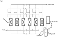
- the PSA system 4 of figure 1 is represented in more details in figure 2 .
- a pressure swing adsorption system or PSA system suitable for implementing the process according to the invention comprises at least one adsorber vessel (also called adsorber column or simply adsorber) filled with at least one adsorbent that selectively adsorbs nitrogen, in particular at least two adsorber vessels.
- a adsorber vessel also called adsorber column or simply adsorber
- a continuous production can be ensured by a suitable production buffer tank.
- each adsorber vessel undergoes a pressure cycle, with a phase interval between the adsorber vessels.
- the PSA system comprises at least six adsorber vessels 6, and the apparatus comprises a first buffer tank 7 (or capacity vessel) and a second buffer tank 8 for storing two portions of the generated off gas, each in a separate buffer tank.
- the adsorber vessels 6 are suitably connected to each other by a set of conduits and valves (not represented), allowing them to be fed, discharged and to undergo a pressure cycle with a phase interval between the adsorber vessels 6.
- conduits 12 are connecting the adsorber vessels 6 with the first and second buffer tanks 7, 8, said conduits being part of either the fuel off gas line 10 or of the bypass line 11.
- PSA cycle The pressure swing adsorption of the PSA system 4 follows a pressure cycle, also called "PSA cycle", comprising the following steps :
- Production step A the effluent gas is co-currently fed to the PSA system 4. Nitrogen is more strongly adsorbed on the adsorbent than hydrogen. Therefore, a major part of the hydrogen flows through the adsorber vessel and the major part of a major part of the nitrogen is stopped in the adsorber vessel. The hydrogen product is thereby generated at the pressure cycle high pressure.
- Co-current depressurization and provide purge step E1D+PP the adsorber vessel is co-currently depressurized to an intermediate pressure of the pressure cycle.
- the least adsorbable hydrogen is further displaced towards the exit of the adsorber vessel and a hydrogen rich gas is discharged from the vessel.
- One part of the discharged hydrogen rich gas will be used as a purge gas, while another part will be used as a counter-current repressurization gas.
- Blow down step BD the adsorbent is regenerated by counter-currently reducing or further reducing the pressure in the adsorber vessel, typically by opening a valve making the gases within the adsorber vessel exit the adsorber vessel as off gas.
- Purge step P1 during a purge step, the adsorber vessel is typically counter-currently swept by the purge gas, like it is the case in the embodiment of figure 3 and 4 , and an off gas exits the adsorber vessel.
- the purge gas contains a gas that is less strongly adsorbed by the adsorbent and can be provided by a co-current depressurization step and/or provide purge step of the pressure cycle.
- the purge is provided by the co-current depressurization and provide purge step E1D+PP.
- the partial pressure of the nitrogen decreases in the adsorber vessel, acting as a driving force for the desorption of the nitrogen from the adsorbent. This is realized at a low pressure of the pressure cycle, in particular the lowest pressure of the pressure cycle.
- Counter-current repressurization step E1P the adsorber is pressurized using the counter-current repressurization gas fed counter-currently to the adsorber vessel.
- Co-current repressurization step FEED REP the adsorber is pressurized until the pressure cycle high pressure with for example the effluent gas as a feed.
- Co-current and counter-current are defined with respect to the circulation of the effluent gas fed to the at least one adsorber vessel and the circulation of the hydrogen product gas exiting the at least one adsorber vessel, during a production step.
- Co-current is the same direction of circulation as the effluent gas and the hydrogen product gas during a production step and counter-current is the opposite direction of circulation.
- a particular step is distinguished from the preceding step or from the following step for example through one of the following reasons :
- phase time is equal to the duration of the pressure cycle divided by the number of adsorber vessels.
- the scope of the invention includes a phase during which several steps of the pressure cycle are performed and conversely a step of the pressure cycle being performed over several phases.
- the PSA off gas is generated during the blow down step BD and the purge step P1 and these steps are constituting a period of time of the pressure cycle called off gas generation period of time.
- the off gas generation period of time comprises several steps of the pressure cycle during which several off gas streams are generated.
- One part of said off gas generation period of time is called a nitrogen richer off gas generation period of time and can comprise or can consist of one part of a pressure cycle step, an entire pressure cycle step, more than one pressure cycle step, for example an entire pressure cycle step plus one part of the next or previous step or a plurality of pressure cycle steps. In case of a plurality of steps of the pressure cycle, several off gas streams are generated during these steps.
- a fuel off gas generation period of time Another part, for example the rest, of the off gas generation period of time is called a fuel off gas generation period of time.
- a fuel off gas being part of the generated PSA off gas is generated.
- the fuel off gas generation period of time can comprise several steps of the pressure cycle during which several off gas streams are generated.
- a nitrogen richer off gas being part of the generated PSA off gas is generated, for example from a plurality of off gas streams generated during multiple steps comprised in the nitrogen richer off gas generation period of time.
- the fuel off gas generated is routed as a fuel off gas or fuel stream to a burner of the furnace 5 and combusted to provide heat to the endothermic cracking reaction of the ammonia feed stream.
- the nitrogen richer off gas has a higher nitrogen content in average over said nitrogen richer off gas generation period of time (ie. taking into account possible fluctuations) than the fuel off gas, for example the nitrogen richer off gas has 80% or more, preferably 85% or more of nitrogen content while the fuel off gas has less than 80% of nitrogen content.
- the nitrogen richer off gas is therefore routed as off gas (B) and diverted from the furnace, thereby not participating to the heat input to the endothermic cracking reaction of the ammonia feed stream. Not using the off gas (B) directly as a fuel, which would be done for example by mixing it with off gas (A), results in less nitrogen in the off gas (A) flow rate provided as fuel to the furnace 5. The combustion properties of the fuel off gas in the furnace 5 are thus enhanced, increasing the radiation efficiency and stabilizing the flame. Off gas (A) and (B) can be routed as separate streams simultaneously and continuously from the PSA system 4 as a whole.
- the nitrogen richer off gas generation period of time comprises the first part or beginning of the purge step P1, for example the first fifteen seconds, or even the first thirty seconds.
- the low nitrogen content of the purge gas filling spaces of the adsorber vessel between the adsorbent and the adsorber shell, in contrast with the adsorbent loaded with still a high nitrogen content, creates a gradient in concentration between the adsorbent and said spaces of the adsorber vessel. This gradient, along with the low pressure in the adsorber vessel during the purge step, act as a driving force and ensure a significant part of the nitrogen desorption and adsorbent regeneration.
- the purge gas will come into contact with the adsorbent for the first time after the production step A during the beginning of said purge step P1. Therefore, the beginning of the purge step P1 will see the highest gradient in concentration and the off gas generated during the beginning of the purge step P1, designated as nitrogen richer off gas, will typically have the highest nitrogen content among the off gas generated during the pressure cycle and its off gas generation period of time.
- the inventors have found that it is advantageous not to consider the whole generated off gas as a bulk of different flows coming out of one or more adsorber vessel(s) during several off gas generation steps, as in the prior art, but to branch off this particular flow of nitrogen richer off gas and to send a remaining part of generated off gas, having a lower nitrogen content, to the furnace. It is to be understood that the invention covers also cases wherein the nitrogen richer off gas generation period of time comprises an entire purge step. In cases wherein the pressure cycle comprises multiple purge steps, the invention covers also cases where the nitrogen richer off gas generation period of time comprises several of these purge steps.
- the pressure cycle comprises other steps during which off gas is generated with a lower nitrogen content, at least part of said off gas with a lower nitrogen content being routed from the PSA system 4 as a whole as a fuel stream and combusted to provide heat to the endothermic ammonia cracking reaction.
- the nitrogen richer off gas generation period of time comprises the last part or end of the blow down step BD.
- the inventors have found that it is advantageous to branch off this gas exiting with a higher nitrogen content to send a remaining part of generated off gas, having a lower nitrogen content, to the furnace.
- the invention covers also cases where the nitrogen richer off gas generation period of time comprises an entire blow down step.
- the pressure cycle comprises multiple blow down steps
- the invention covers also cases where the nitrogen richer off gas generation period of time comprises several of these blow down steps. This applies as long as the pressure cycle comprises other steps during which off gas is generated with a lower nitrogen content, at least part of said off gas with a lower nitrogen content being routed from the PSA system 4 as a whole as a fuel stream and combusted to provide heat to the endothermic ammonia cracking reaction.
- the apparatus comprises a membrane system 9 capable of splitting off gas in a hydrogen rich permeate and a nitrogen rich retentate.
- the bypass line 11 is connecting the second buffer tank 8 with the membrane system 9.
- the apparatus comprises a compressor (not represented) for compressing said off gas fed to the membrane system 9.
- the hydrogen rich permeate can be provided as an additional fuel to the furnace 5 through a permeate fueling conduit (not represented) connecting a permeate side of the membrane system 9 with the furnace 5.
- the off gas stored in the second buffer tank 8 can be fed to a second PSA system to be further purified, can be fed to a vent to be vented or can be fed to a gas flare to be flared.
Landscapes
- Chemical & Material Sciences (AREA)
- Organic Chemistry (AREA)
- Chemical Kinetics & Catalysis (AREA)
- Engineering & Computer Science (AREA)
- Combustion & Propulsion (AREA)
- Inorganic Chemistry (AREA)
- Health & Medical Sciences (AREA)
- General Health & Medical Sciences (AREA)
- Analytical Chemistry (AREA)
- General Chemical & Material Sciences (AREA)
- Oil, Petroleum & Natural Gas (AREA)
- Hydrogen, Water And Hydrids (AREA)
Priority Applications (2)
| Application Number | Priority Date | Filing Date | Title |
|---|---|---|---|
| EP23189556.6A EP4501433A1 (de) | 2023-08-03 | 2023-08-03 | Rückgewinnung von wasserstoff aus einem ammoniak-cracking-verfahren |
| PCT/EP2024/068075 WO2025026622A1 (en) | 2023-08-03 | 2024-06-27 | Recovery of hydrogen from an ammonia cracking process |
Applications Claiming Priority (1)
| Application Number | Priority Date | Filing Date | Title |
|---|---|---|---|
| EP23189556.6A EP4501433A1 (de) | 2023-08-03 | 2023-08-03 | Rückgewinnung von wasserstoff aus einem ammoniak-cracking-verfahren |
Publications (1)
| Publication Number | Publication Date |
|---|---|
| EP4501433A1 true EP4501433A1 (de) | 2025-02-05 |
Family
ID=87556226
Family Applications (1)
| Application Number | Title | Priority Date | Filing Date |
|---|---|---|---|
| EP23189556.6A Withdrawn EP4501433A1 (de) | 2023-08-03 | 2023-08-03 | Rückgewinnung von wasserstoff aus einem ammoniak-cracking-verfahren |
Country Status (2)
| Country | Link |
|---|---|
| EP (1) | EP4501433A1 (de) |
| WO (1) | WO2025026622A1 (de) |
Citations (5)
| Publication number | Priority date | Publication date | Assignee | Title |
|---|---|---|---|---|
| US20060130651A1 (en) * | 2004-12-22 | 2006-06-22 | Bizjak Travis A | Systems and methods for regulating heating assembly operation through pressure swing adsorption purge control |
| EP2095862A1 (de) * | 2002-02-15 | 2009-09-02 | L'Air Liquide Société Anonyme pour l'Etude et l'Exploitation des Procédés Georges Claude | Herstellungsverfahren von Wasserstoff aus wasserstoffreichem Knallgas |
| US20170203963A1 (en) * | 2016-01-19 | 2017-07-20 | Fluor Technologies Corporation | Production of pure hydrogen from ammonia rich sour water stripper overhead |
| US20210053009A1 (en) * | 2019-08-21 | 2021-02-25 | Air Products And Chemicals, Inc. | Reducing Fluctuations in Tail Gas Flow and Fuel Property from an Adsorption Unit |
| WO2022265650A1 (en) * | 2021-06-18 | 2022-12-22 | Air Products And Chemicals, Inc. | Ammonia cracking process |
-
2023
- 2023-08-03 EP EP23189556.6A patent/EP4501433A1/de not_active Withdrawn
-
2024
- 2024-06-27 WO PCT/EP2024/068075 patent/WO2025026622A1/en active Pending
Patent Citations (5)
| Publication number | Priority date | Publication date | Assignee | Title |
|---|---|---|---|---|
| EP2095862A1 (de) * | 2002-02-15 | 2009-09-02 | L'Air Liquide Société Anonyme pour l'Etude et l'Exploitation des Procédés Georges Claude | Herstellungsverfahren von Wasserstoff aus wasserstoffreichem Knallgas |
| US20060130651A1 (en) * | 2004-12-22 | 2006-06-22 | Bizjak Travis A | Systems and methods for regulating heating assembly operation through pressure swing adsorption purge control |
| US20170203963A1 (en) * | 2016-01-19 | 2017-07-20 | Fluor Technologies Corporation | Production of pure hydrogen from ammonia rich sour water stripper overhead |
| US20210053009A1 (en) * | 2019-08-21 | 2021-02-25 | Air Products And Chemicals, Inc. | Reducing Fluctuations in Tail Gas Flow and Fuel Property from an Adsorption Unit |
| WO2022265650A1 (en) * | 2021-06-18 | 2022-12-22 | Air Products And Chemicals, Inc. | Ammonia cracking process |
Also Published As
| Publication number | Publication date |
|---|---|
| WO2025026622A1 (en) | 2025-02-06 |
Similar Documents
| Publication | Publication Date | Title |
|---|---|---|
| US5669960A (en) | Hydrogen generation process | |
| CA2567195C (en) | Continuous feed three-bed pressure swing adsorption system | |
| KR101388266B1 (ko) | 고로가스의 분리방법 및 장치 | |
| US5294247A (en) | Adsorption process to recover hydrogen from low pressure feeds | |
| US4316880A (en) | Process for producing carbon monoxide and hydrogen from methanol | |
| CN113784777B (zh) | 用于生产氢气和二氧化碳的变压吸附工艺 | |
| KR20110049784A (ko) | 연도 가스로부터의 이산화탄소 회수 | |
| US11485637B2 (en) | Process for purifying a synthesis gas | |
| WO2008142009A1 (en) | Process for purifying a gas by cpsa having two regeneration stages, and purification unit for implementing this process | |
| JP2001187309A (ja) | 水素製造のための圧力変動吸着法 | |
| NO313989B1 (no) | Fremgangsmåte for ved forbrenning å fjerne koksavsetninger på partikkelformig materiale | |
| US11571652B2 (en) | Method of purifying hydrogen supplied from a storage cavern | |
| WO2021130530A1 (en) | Regeneration schemes for a two-stage adsorption process for claus tail gas treatment | |
| US7699907B2 (en) | Apparatus and methods for gas separation | |
| EP4501433A1 (de) | Rückgewinnung von wasserstoff aus einem ammoniak-cracking-verfahren | |
| JP4316386B2 (ja) | 水素リッチの供給ガスから水素を製造するための方法および装置 | |
| CN213101492U (zh) | 从石化排放尾气中同时回收氢气和甲烷气的装置 | |
| AU2021377152A9 (en) | A process and plant for producing ultrahigh-purity hydrogen from low-grade hydrogen gas | |
| JP2005517622A5 (de) | ||
| US20230331550A1 (en) | Process and apparatus for producing low-nitrogen synthesis gas from nitrogen-containing natural gas | |
| JP2005177716A (ja) | 水素psa精製装置から排出されるオフガスの処理方法 | |
| EP4585294A2 (de) | Druckwechseladsorption mit zwei zugeführten, drei produktströmen | |
| US12036505B2 (en) | Three-product pressure swing adsorption system | |
| JPS60155519A (ja) | 吸着法を使用して一酸化炭素を含む混合ガスより一酸化炭素を精製する方法 | |
| EP3626328A1 (de) | Verfahren zur trennung einer gasmischung durch druckwechseladsorption |
Legal Events
| Date | Code | Title | Description |
|---|---|---|---|
| PUAI | Public reference made under article 153(3) epc to a published international application that has entered the european phase |
Free format text: ORIGINAL CODE: 0009012 |
|
| STAA | Information on the status of an ep patent application or granted ep patent |
Free format text: STATUS: THE APPLICATION HAS BEEN PUBLISHED |
|
| AK | Designated contracting states |
Kind code of ref document: A1 Designated state(s): AL AT BE BG CH CY CZ DE DK EE ES FI FR GB GR HR HU IE IS IT LI LT LU LV MC ME MK MT NL NO PL PT RO RS SE SI SK SM TR |
|
| STAA | Information on the status of an ep patent application or granted ep patent |
Free format text: STATUS: REQUEST FOR EXAMINATION WAS MADE |
|
| 17P | Request for examination filed |
Effective date: 20250805 |
|
| STAA | Information on the status of an ep patent application or granted ep patent |
Free format text: STATUS: THE APPLICATION IS DEEMED TO BE WITHDRAWN |
|
| 18D | Application deemed to be withdrawn |
Effective date: 20250806 |