EP4501418A1 - Golfball mit mindestens einer radarerkennbaren markierung - Google Patents
Golfball mit mindestens einer radarerkennbaren markierung Download PDFInfo
- Publication number
- EP4501418A1 EP4501418A1 EP24192942.1A EP24192942A EP4501418A1 EP 4501418 A1 EP4501418 A1 EP 4501418A1 EP 24192942 A EP24192942 A EP 24192942A EP 4501418 A1 EP4501418 A1 EP 4501418A1
- Authority
- EP
- European Patent Office
- Prior art keywords
- mark
- golf ball
- radar
- stripe
- radar detectable
- Prior art date
- Legal status (The legal status is an assumption and is not a legal conclusion. Google has not performed a legal analysis and makes no representation as to the accuracy of the status listed.)
- Withdrawn
Links
Images


Classifications
-
- A—HUMAN NECESSITIES
- A63—SPORTS; GAMES; AMUSEMENTS
- A63B—APPARATUS FOR PHYSICAL TRAINING, GYMNASTICS, SWIMMING, CLIMBING, OR FENCING; BALL GAMES; TRAINING EQUIPMENT
- A63B37/00—Solid balls; Rigid hollow balls; Marbles
- A63B37/0003—Golf balls
- A63B37/0022—Coatings, e.g. paint films; Markings
- A63B37/00221—Coatings, e.g. paint films; Markings characterised by the material
-
- A—HUMAN NECESSITIES
- A63—SPORTS; GAMES; AMUSEMENTS
- A63B—APPARATUS FOR PHYSICAL TRAINING, GYMNASTICS, SWIMMING, CLIMBING, OR FENCING; BALL GAMES; TRAINING EQUIPMENT
- A63B43/00—Balls with special arrangements
- A63B43/06—Balls with special arrangements with illuminating devices ; with reflective surfaces
-
- A—HUMAN NECESSITIES
- A63—SPORTS; GAMES; AMUSEMENTS
- A63B—APPARATUS FOR PHYSICAL TRAINING, GYMNASTICS, SWIMMING, CLIMBING, OR FENCING; BALL GAMES; TRAINING EQUIPMENT
- A63B37/00—Solid balls; Rigid hollow balls; Marbles
- A63B37/0003—Golf balls
- A63B37/0022—Coatings, e.g. paint films; Markings
-
- A—HUMAN NECESSITIES
- A63—SPORTS; GAMES; AMUSEMENTS
- A63B—APPARATUS FOR PHYSICAL TRAINING, GYMNASTICS, SWIMMING, CLIMBING, OR FENCING; BALL GAMES; TRAINING EQUIPMENT
- A63B37/00—Solid balls; Rigid hollow balls; Marbles
- A63B37/0003—Golf balls
- A63B37/0022—Coatings, e.g. paint films; Markings
- A63B37/00222—Physical properties, e.g. hardness
-
- A—HUMAN NECESSITIES
- A63—SPORTS; GAMES; AMUSEMENTS
- A63B—APPARATUS FOR PHYSICAL TRAINING, GYMNASTICS, SWIMMING, CLIMBING, OR FENCING; BALL GAMES; TRAINING EQUIPMENT
- A63B37/00—Solid balls; Rigid hollow balls; Marbles
- A63B37/0003—Golf balls
- A63B37/0038—Intermediate layers, e.g. inner cover, outer core, mantle
- A63B37/0039—Intermediate layers, e.g. inner cover, outer core, mantle characterised by the material
-
- A—HUMAN NECESSITIES
- A63—SPORTS; GAMES; AMUSEMENTS
- A63B—APPARATUS FOR PHYSICAL TRAINING, GYMNASTICS, SWIMMING, CLIMBING, OR FENCING; BALL GAMES; TRAINING EQUIPMENT
- A63B37/00—Solid balls; Rigid hollow balls; Marbles
- A63B37/0003—Golf balls
- A63B37/0038—Intermediate layers, e.g. inner cover, outer core, mantle
- A63B37/004—Physical properties
-
- A—HUMAN NECESSITIES
- A63—SPORTS; GAMES; AMUSEMENTS
- A63B—APPARATUS FOR PHYSICAL TRAINING, GYMNASTICS, SWIMMING, CLIMBING, OR FENCING; BALL GAMES; TRAINING EQUIPMENT
- A63B37/00—Solid balls; Rigid hollow balls; Marbles
- A63B37/0003—Golf balls
- A63B37/005—Cores
- A63B37/0051—Materials other than polybutadienes; Constructional details
-
- A—HUMAN NECESSITIES
- A63—SPORTS; GAMES; AMUSEMENTS
- A63B—APPARATUS FOR PHYSICAL TRAINING, GYMNASTICS, SWIMMING, CLIMBING, OR FENCING; BALL GAMES; TRAINING EQUIPMENT
- A63B37/00—Solid balls; Rigid hollow balls; Marbles
- A63B37/0003—Golf balls
- A63B37/005—Cores
- A63B37/006—Physical properties
-
- A—HUMAN NECESSITIES
- A63—SPORTS; GAMES; AMUSEMENTS
- A63B—APPARATUS FOR PHYSICAL TRAINING, GYMNASTICS, SWIMMING, CLIMBING, OR FENCING; BALL GAMES; TRAINING EQUIPMENT
- A63B43/00—Balls with special arrangements
- A63B43/004—Balls with special arrangements electrically conductive, e.g. for automatic arbitration
-
- A—HUMAN NECESSITIES
- A63—SPORTS; GAMES; AMUSEMENTS
- A63B—APPARATUS FOR PHYSICAL TRAINING, GYMNASTICS, SWIMMING, CLIMBING, OR FENCING; BALL GAMES; TRAINING EQUIPMENT
- A63B24/00—Electric or electronic controls for exercising apparatus of preceding groups; Controlling or monitoring of exercises, sportive games, training or athletic performances
- A63B24/0021—Tracking a path or terminating locations
- A63B2024/0028—Tracking the path of an object, e.g. a ball inside a soccer pitch
-
- A—HUMAN NECESSITIES
- A63—SPORTS; GAMES; AMUSEMENTS
- A63B—APPARATUS FOR PHYSICAL TRAINING, GYMNASTICS, SWIMMING, CLIMBING, OR FENCING; BALL GAMES; TRAINING EQUIPMENT
- A63B24/00—Electric or electronic controls for exercising apparatus of preceding groups; Controlling or monitoring of exercises, sportive games, training or athletic performances
- A63B24/0021—Tracking a path or terminating locations
- A63B2024/0056—Tracking a path or terminating locations for statistical or strategic analysis
-
- A—HUMAN NECESSITIES
- A63—SPORTS; GAMES; AMUSEMENTS
- A63B—APPARATUS FOR PHYSICAL TRAINING, GYMNASTICS, SWIMMING, CLIMBING, OR FENCING; BALL GAMES; TRAINING EQUIPMENT
- A63B2209/00—Characteristics of used materials
-
- A—HUMAN NECESSITIES
- A63—SPORTS; GAMES; AMUSEMENTS
- A63B—APPARATUS FOR PHYSICAL TRAINING, GYMNASTICS, SWIMMING, CLIMBING, OR FENCING; BALL GAMES; TRAINING EQUIPMENT
- A63B2220/00—Measuring of physical parameters relating to sporting activity
- A63B2220/30—Speed
- A63B2220/34—Angular speed
- A63B2220/35—Spin
-
- A—HUMAN NECESSITIES
- A63—SPORTS; GAMES; AMUSEMENTS
- A63B—APPARATUS FOR PHYSICAL TRAINING, GYMNASTICS, SWIMMING, CLIMBING, OR FENCING; BALL GAMES; TRAINING EQUIPMENT
- A63B2220/00—Measuring of physical parameters relating to sporting activity
- A63B2220/30—Speed
- A63B2220/36—Speed measurement by electric or magnetic parameters
-
- A—HUMAN NECESSITIES
- A63—SPORTS; GAMES; AMUSEMENTS
- A63B—APPARATUS FOR PHYSICAL TRAINING, GYMNASTICS, SWIMMING, CLIMBING, OR FENCING; BALL GAMES; TRAINING EQUIPMENT
- A63B2220/00—Measuring of physical parameters relating to sporting activity
- A63B2220/80—Special sensors, transducers or devices therefor
- A63B2220/89—Field sensors, e.g. radar systems
-
- A—HUMAN NECESSITIES
- A63—SPORTS; GAMES; AMUSEMENTS
- A63B—APPARATUS FOR PHYSICAL TRAINING, GYMNASTICS, SWIMMING, CLIMBING, OR FENCING; BALL GAMES; TRAINING EQUIPMENT
- A63B37/00—Solid balls; Rigid hollow balls; Marbles
- A63B37/0003—Golf balls
- A63B37/0023—Covers
- A63B37/0024—Materials other than ionomers or polyurethane
-
- A—HUMAN NECESSITIES
- A63—SPORTS; GAMES; AMUSEMENTS
- A63B—APPARATUS FOR PHYSICAL TRAINING, GYMNASTICS, SWIMMING, CLIMBING, OR FENCING; BALL GAMES; TRAINING EQUIPMENT
- A63B37/00—Solid balls; Rigid hollow balls; Marbles
- A63B37/0003—Golf balls
- A63B37/0023—Covers
- A63B37/0029—Physical properties
-
- A—HUMAN NECESSITIES
- A63—SPORTS; GAMES; AMUSEMENTS
- A63B—APPARATUS FOR PHYSICAL TRAINING, GYMNASTICS, SWIMMING, CLIMBING, OR FENCING; BALL GAMES; TRAINING EQUIPMENT
- A63B43/00—Balls with special arrangements
- A63B43/008—Balls with special arrangements with means for improving visibility, e.g. special markings or colours
Definitions
- the present invention relates generally to golf balls including a mark, or a plurality of marks, for improving the detection and tracking thereof by radar tracking systems.
- Radar reflective stickers are typically placed on the outer surface of the golf ball in order for radar tracking systems to obtain launch condition data.
- challenges associated with the use of these stickers including, for example, accurate positioning of the stickers on the ball, alignment of the stickers relative to the golfer and tee, time and effort required to place the stickers on the ball, and lack of durability of the stickers, which further leads to a decrease in the quality of launch condition data and the need to replace the stickers.
- a golf ball that provides one or more of the following benefits: improved quality of golf ball launch condition data collected by radar tracking systems, and enhanced experience for the end users of these radar tracking systems.
- the present disclosure is directed to a golf ball comprising at least one layer with a mark, or a plurality of marks, disposed on a surface thereof.
- the mark has a continuous shape and is formed from a radar detectable material.
- the golf ball additionally has one or more of the following properties:
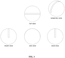
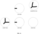
- the mark is formed from a radar detectable material and has dimensions such that every great circle path on the golf ball layer surface on which the mark is disposed intersects the mark.
- the mark is formed from a radar detectable material and has a continuous shape comprising three or more intersecting stripes.
- the at least one layer has a plurality of radar detectable marks disposed on a surface thereof.
- the radar detectable marks have a resistivity of from 0.1 Ohms to 25 Ohms.
- every 0.025 inch wide great circle path on the golf ball layer surface on which the radar detectable marks are disposed intersects at least one of the marks.
- every great circle path on the golf ball layer surface on which the radar detectable marks are disposed intersects at least one of the marks.
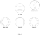
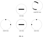
- the plurality of radar detectable marks includes a first mark and a second mark, wherein the first mark has a continuous, irregular shape and the second mark has a basic shape selected from basic nonpolygonal shapes, regular polygons, and irregular polygons.
- suitable basic nonpolygonal shapes include circles, rings, and crescents.
- suitable regular polygons include squares and equilateral triangles.
- suitable irregular polygons include rectangles, non-equilateral triangles, and chevrons.
- the plurality of radar detectable marks includes a first mark and a second mark, wherein the first mark has a continuous, irregular shape comprising a plurality of intersecting stripes, and the second mark has an irregular shape that is different from the first mark.
- the plurality of radar detectable marks includes a third mark, the third mark having either an irregular shape or a regular shape.
- the radar detectable marks when all of the radar detectable marks present on any layer of the ball are radially projected onto the outer surface of the ball, the radar detectable marks have a total surface coverage of from 1% to 20%.
- the golf ball comprises two or more layers, wherein at least two of the two or more layers have one or more radar detectable marks disposed on a surface thereof.
- the radar detectable marks present on any layer of the ball are radially projected onto the outer surface of the ball, every 0.025 inch wide great circle path on the golf ball outer surface intersects at least one of the marks.
- the golf ball has a plurality of radar detectable marks disposed on a single layer thereof.
- the plurality of radar detectable marks includes at least eleven equally-spaced, non-circular-shaped marks.
- the number of equally-spaced, non-circular-shaped marks is a prime number from 11 to 37.
- the golf ball has a plurality of radar detectable marks disposed among two or more layers thereof.
- the plurality of radar detectable marks includes at least eleven non-circular-shaped marks.
- the radar detectable marks are equally spaced.
- the number of equally-spaced, non-circular-shaped marks is a prime number from 11 to 37.
- the total surface coverage of all radar detectable marks present is from 0.1% to 4.0%.
- the golf ball has a layer with a radar detectable mark disposed on a surface thereof, and the mark has a continuous non-circular shape and a surface coverage of from 0.1% to 4.0%.
- the golf ball has a plurality of radar detectable marks disposed among two or more surfaces thereof, and, when all of the radar detectable marks present on any surface of any layer of the ball are radially projected onto the outer surface of the ball, the radar detectable marks have an overall continuous non-circular shape.
- the golf ball has one or more radar detectable marks disposed on a surface of at least one layer thereof, the total number of radar detectable marks present is two or more, and the radar detectable marks have a total surface coverage of from 0.1% to 4.0%.
- the golf ball has a plurality of radar detectable marks disposed on any single layer or among two or more layers thereof.
- the resulting overall pattern of projected radar detectable marks comprises a series of three or more marks where each mark in the series has a geometric center located on a 1.5 mm wide great circle band on the outer surface of the ball.
- the overall pattern of projected marks consists essentially of the plurality of marks positioned along the great circle.
- the portion of the great circle along which the plurality of marks are positioned has a length of no more than half the circumference of the ball.
- the golf ball has a plurality of radar detectable marks disposed on any single layer or among two or more layers thereof.
- the resulting overall pattern of projected radar detectable marks comprises a first great circle series of three or more marks, where each mark in the series has a geometric center located on a first 1.5 mm wide great circle band on the outer surface of the ball, and a second great circle series of three or more marks, where each mark in the series has a geometric center located on a second 1.5 mm wide great circle band on the outer surface of the ball.
- the present disclosure is directed to a golf ball comprising at least one layer with a mark, or a plurality of marks, disposed on a surface thereof.
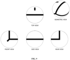
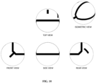
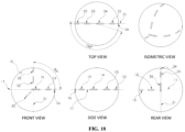
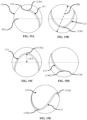
- a golf ball is disclosed that has at least one radar detectable mark such that a projected pattern is formed when the at least one radar detectable mark is radially projected onto an outer surface of the golf ball.
- the projected pattern can comprise a first wave profile mapped along a path defined by a first spherical arc on the outer surface of the golf ball.
- the projected pattern comprises at least one first crest and at least one first trough.
- the first spherical arc can be defined along a first great circle on the outer surface of the golf ball.
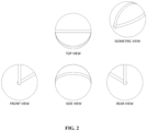
- the projected pattern can comprise a first terminal end and a second terminal end that are circumferentially spaced apart from each other to define a wave angular extent.
- the terminal ends can be spaced apart from each other by at least 45 degrees, in one example.
- the first terminal end and the second terminal end can be circumferentially spaced apart by 240 degrees - 300 degrees, in one example.
- the wave angular extent can extend for at least 45 degrees, and preferably can extend for 240 degrees - 300 degrees.
- the wave angular extent can extend for 270 degrees, in one example.
- the circumferential spacing of the terminal ends of the wave profiles can vary in order to cover a predetermined wavelength or period.
- two parallel wave profiles can have varying lengths to account for different positions relative to the printed surface and to align the wave angular extents of the two wave profiles.
- the projected pattern can extend for at least 1.0 period in one example. In one example, the projected pattern can extend for less than 5.0 periods.
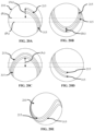
- An amplitude of the first wave profile can have a relationship with the diameter of the golf ball.
- the amplitude is no greater than 40% of a diameter of the golf ball.
- the amplitude is no greater than 40% of a diameter of the golf ball cased core.
- the amplitude is no greater than 40% of a diameter of a golf ball sub-assembly.
- the amplitude is 5% - 50% of a diameter of the golf ball, the amplitude is 10% - 30% of a diameter of the golf ball, or the amplitude is 15% - 25% of a diameter of the golf ball.
- the amplitude is 10% - 60% of a diameter of the golf ball cased core, the amplitude is 20% - 50% of a diameter of the golf ball cased core, or the amplitude is 25% - 40% of a diameter of the golf ball cased core. In other examples, the amplitude is 5% - 55% of a diameter of a golf ball sub-assembly, the amplitude is 15% - 45% of a diameter of a golf ball sub-assembly, or the amplitude is 25% - 40% of a diameter of a golf ball sub-assembly.
- the amplitude can be measured to a mid-point, center, or middle portion of the marking or projected pattern. In another example, the amplitude can be defined as at any two corresponding points on the spherical arc which are equidistant from the central axis of the wave profile.
- the first wave profile can be formed according to a variety of wave profiles.
- the wave profile can be one of: a sine wave, a sawtooth wave, a triangular wave, or a square wave.
- multiple wave forms can be combined.
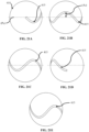
- the at least one radar detectable mark can be disposed on a single layer in one example.
- the at least one radar detectable mark can be comprised of a plurality of radar detectable marks that are disposed among more than one layer.
- the projected pattern can be formed as a continuous, uninterrupted strip, in one example.
- the projected pattern can be formed as a plurality of discrete strips that are spaced apart from each other and aligned with each other such that the discrete strips define a wave profile in the aggregate.
- the discrete strips are centered about a common through line or track such that the overall wave profile is defined by the discrete strips.
- the radar detectable mark can have a width of 1.0 mm - 5.0 mm.
- the first wave profile can have an amplitude of 7.0 mm - 15.0 mm.
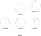
- the projected pattern can further comprise a second wave profile with at least one second crest and at least one second trough.
- the first wave profile can be comprised of a plurality of first points and the second wave profile can be comprised of a plurality of second points.
- Each first point along the first wave profile and each closest adjacent second point along the second wave profile can be equidistant from each other such that a uniform normal distance is defined along an entirety of the first wave profile and the second wave profile.
- the uniform normal distance can be 4.0 mm - 6.0 mm.
- the first and second wave profiles can be parallel to each other. In another aspect, a normal distance between the wave profiles can vary and can be non-uniform.
- the first wave profile and the second wave profile can each have a predetermined amplitude that is identical to each other, such that the uniform normal distance is at least half of the predetermined amplitude, and the uniform normal distance is no greater than twice the predetermined amplitude.
- the second wave profile can be mapped along a path defined by a second spherical arc that is positioned away from the first spherical arc.
- the golf ball can have at least one radar detectable mark such that a projected pattern is formed when the at least one radar detectable mark is radially projected onto an outer surface of the golf ball.
- the projected pattern can comprise a first wave profile defined by a periodic function and mapped along a path defined by a first spherical arc on the outer surface of the golf ball.
- the periodic function can be selected from one of: a sine wave, a sawtooth wave, a triangle wave, or a square wave.
- the wave profile can be defined as a combination of wave forms to produce another periodic function. Any one or more of a sine wave, a sawtooth wave, a triangle wave, or a square wave can be combined, in addition to any other function or periodic profile.
- the projected pattern can have a wave angular extent of 45 degrees - 270 degrees, in one example.
- the periodic function can repeat for at least 1.0 period.
- the projected pattern can further include a second wave profile with at least one second crest and at least one second trough.
- a uniform normal distance can be defined along an entirety of the first wave profile and the second wave profile.
- the first wave profile can have a first amplitude
- the second wave profile can have a second amplitude.
- the uniform normal distance can be less than half of the first amplitude.
- the uniform normal distance can be less than half of the second amplitude.
- the first amplitude can be no greater than 40% of a diameter of at least one of: the golf ball, a cased core of the golf ball, or a sub-assembly of the golf ball.
- the golf ball can have at least one radar detectable mark such that a projected pattern is formed when the at least one radar detectable mark is radially projected onto an outer surface of the golf ball.
- the projected pattern can comprise a first wave profile defined by a periodic function and mapped along a path defined by a first spherical arc on the outer surface of the golf ball.
- the periodic function can be a sine wave, and the periodic function can repeat for at least 1.0 period.
- a golf ball has at least one radar detectable mark disposed on any single layer or among two or more layers thereof, such that the at least one radar detectable mark present on any layer of the golf ball is radially projected onto an outer surface of the golf ball to form an overall pattern, and the at least one radar detectable mark can be formed from a radar detectable material comprising: a resin; and a first plurality of conductive metal pigments.
- a radar detectable material comprising: a resin; and a first plurality of conductive metal pigments.
- the term conductive refers to electrical conductivity, and the terms conductive and electrically conductive are used interchangeably herein.
- the present disclosure provides for a radar reflective material or marking that is comprised, in part, of conductive pigments.
- the pigments can be formed from various materials, and can be formed from non-metallic base compositions and/or coatings.
- a first plurality of conductive metal pigments can have an average particle size that is no greater than 10.0 microns, and the first plurality of conductive metal pigments can have an average aspect ratio that is no greater than 10.0.
- One of ordinary skill in the art would understand that the characteristics of the pigments can vary.
- the first plurality of conductive metal pigments can comprise at least one of: silver, nickel, aluminum, titanium, gold, tin, tin oxide, antimony, antimony oxide, copper oxide, platinum, palladium, iridium coated platinum, silver coated copper, silver coated iron, silver coated nickel, or coated core shell pigments.
- the radar detectable material can further comprise a second plurality of conductive metal pigments that are formed from a different material than the first plurality of conductive metal pigments.
- the second plurality of conductive metal pigments can include pigments that are coated by conductive polymers.
- the conductive polymer can be comprised of at least one of: poly (3-4-ethylenedioxythiophene) (PEDOT), PEDOT composites, or polyaniline (PANI).
- PEDOT poly (3-4-ethylenedioxythiophene)
- PANI polyaniline
- the second plurality of conductive metal pigments can be silver coated copper, silver coated iron, or silver coated nickel, in other aspects.
- the radar detectable material can further comprise a second plurality of conductive pigments that are formed from a different material than the first plurality of conductive metal pigments.
- the second plurality of conductive pigments can include metallic pigments, or non-metallic pigments that can be coated by a conductive material.
- the coating and/or the pigment itself can be conductive.
- the second plurality of conductive metal pigments are magnetic pigments. In one aspect, the second plurality of conductive metal pigments are radiopaque pigments. The second plurality of conductive metal pigments can be comprised of tungsten.
- the average particle size of the first plurality of conductive metal pigments is no greater than 5.0 microns. In one aspect, the average particle size of the first plurality of conductive metal pigments is no greater than 7.5 microns. In one aspect, the average particle size of the first plurality of conductive metal pigments is no greater than 10.0 microns. In one aspect, the average particle size of the first plurality of conductive metal pigments is 4.0 microns - 12.0 microns. In one aspect, the average particle size of the first plurality of conductive metal pigments is 1.0 micron - 15.0 microns.
- the average particle size of the first plurality of conductive metal pigments is no greater than 2.0 microns. In one aspect, the average aspect ratio of the first plurality of conductive metal pigments is no greater than 5.0. In one aspect, a relationship between the values for the average aspect ratio (AR) and the average particle size (PS) (in microns) is defined by: 0.5 ⁇ (AR/PS) ⁇ 5.0. In one aspect, a difference between the values for the average aspect ratio and the average particle size (in microns) is no greater than 8.0. In one aspect, a difference between the values for the average aspect ratio and the average particle size (in microns) is no greater than 3.0. In one aspect, a difference between the values for the average aspect ratio and the average particle size (in microns) is no greater than 1.0.
- a first plurality of pigments can be formed from materials other than metals and can be coated with a conductive material.
- the at least one radar detectable mark can have a depth of 1.0 micron - 10.0 microns.
- a width of the at least one radar detectable mark can be no greater than 1.50 mm.
- a width of the at least one radar detectable mark can be no greater than 1.00 mm.
- a width of the at least one radar detectable mark is 0.75 mm - 1.00 mm. In one aspect, a width of the at least one radar detectable mark is no greater than 0.75 mm. In one aspect, a width of the at least one radar detectable mark is 0.50 mm - 0.75 mm.
- the width, as well as all other parameters, measurements, dimensions, etc., of the mark can vary.
- the resin can have a flexural or flex modulus of at least 2.0 MPa, in one aspect.
- the resin can have a flex modulus of 1.0 MPa - 18.0 MPa, in one aspect.
- the flex modulus can be tested according to ASTM D790. One of ordinary skill in the art would understand that other testing standards could be used.
- the sheet resistance values can refer to values associated with the material(s) forming the mark, and not necessarily the values exhibited by a golf ball including said mark(s). For instance, when referring to the sheet resistance of the radar detectable mark, the values can refer to the sheet resistance of the material forming the mark.
- the radar detectable mark or material forming the mark can have a sheet resistance of 0.01 Ohm/sq/mil - 0.10 Ohm/sq/mil. In one aspect, the radar detectable mark or material forming the mark can have a sheet resistance of 0.025 Ohm/sq/mil - 0.075 Ohm/sq/mil. The radar detectable mark or material forming the mark can have a sheet resistance of 0.04 Ohm/sq/mil - 0.06 Ohm/sq/mil. The radar detectable mark or material forming the mark can have a conductivity of no greater than 800,000 Siemens/meter, in one aspect.
- the radar detectable mark or material forming the mark can have a conductivity of 700,000 Siemens/meter - 900,000 Siemens/meter.
- the golf ball can further comprise an adhesion promotor disposed adjacent to the at least one radar detectable mark.
- a golf ball in another aspect, has at least one radar detectable mark disposed on any single layer or among two or more layers thereof, such that the at least one radar detectable mark present on any layer of the golf ball is radially projected onto an outer surface of the golf ball to form an overall pattern, and the at least one radar detectable mark can be formed from a radar detectable material comprising at least one of: copper; silver; conductive polymer; gold; platinum; conductive carbon; nickel; zinc; or aluminum.
- the radar detectable material is comprised of gold. In another aspect, the radar detectable material is comprised of platinum and conductive carbon. In another aspect, the radar detectable material is comprised of silver and zinc. In another aspect, the radar detectable material is comprised of conductive polymer and conductive carbon. In another aspect, the radar detectable material is comprised of nickel. In another aspect, the radar detectable material is comprised of nickel and silver. In another aspect, the radar detectable material is comprised of nickel and conductive carbon. In another aspect, the radar detectable material is comprised of nickel and conductive polymer.
- the golf ball can further comprise an adhesion promotor disposed adjacent to the at least one radar detectable mark.
- a width of the at least one radar detectable mark can be no greater than 1.50 mm. In another aspect, the width of the at least one radar detectable mark is no greater than 1.00 mm. In another aspect, the width of the at least one radar detectable mark is 0.75 mm - 1.00 mm. The width, as well as all other parameters, measurements, dimensions, etc., of the mark can vary.
- the conductive carbon is comprised of at least one of graphene, fibers, nanotubes, or buckminsterfullerene (hereinafter buckyballs).
- the radar detectable mark has a sheet resistance of 0.015 Ohm/sq/mil - 20.0 Ohm/sq/mil.
- the sheet resistance values can vary as one of ordinary skill in the art would appreciate.
- a golf ball in another aspect, has at least one radar detectable mark disposed on any single layer or among two or more layers thereof, such that the at least one radar detectable mark present on any layer of the golf ball is radially projected onto an outer surface of the golf ball to form an overall pattern, and the at least one radar detectable mark can be formed from a radar detectable material comprising an electrically conductive material comprising: a mixture of silver and metal salt, silver coated glass, silver coated copper, a mixture of silver and tin or tin oxide, a mixture of silver and conductive resin, a mixture of silver and conductive carbon, or a mixture of silver and iron-based ceramic.
- the electrically conductive material can comprise the mixture of silver and conductive carbon.
- the mixture of silver and conductive carbon includes a ratio of two parts silver to one part conductive carbon.
- the electrically conductive material comprises silver coated glass.
- the electrically conductive material comprises silver coated copper.
- the electrically conductive material comprises the mixture of silver and metal salt.
- the metal salt in the mixture of silver and the metal salt includes silver chloride.
- the electrically conductive material comprises the mixture of silver and iron-based ceramic.
- the electrically conductive material comprises the mixture of silver and conductive resin.
- the mixture of silver and the metal salt includes a ratio of 80 parts silver to 20 parts metal salt. In another aspect, the mixture of silver and tin or tin oxide includes a ratio of 70 parts silver to 30 parts tin or tin oxide.
- the conductive resin is comprised of at least one of: poly(3, 4 ethylenedioxythiophene) (PEDOT), PEDOT composites, or polyaniline (PANI).
- PEDOT poly(3, 4 ethylenedioxythiophene)
- PANI polyaniline
- the golf ball further comprises an adhesion promotor disposed adjacent to the at least one radar detectable mark.
- a width of the radar detectable mark is no greater than 1.50 mm. In another aspect, a width of the radar detectable mark is no greater than 1.00 mm. In another aspect, a width of the radar detectable mark is 0.75 mm - 1.00 mm. The width, as well as all other parameters, measurements, dimensions, etc., of the mark can vary.
- the at least one radar detectable mark has a sheet resistance of 0.015 Ohm/sq/mil - 20.0 Ohm/sq/mil.
- the sheet resistance values can vary as one of ordinary skill in the art would appreciate.
- a golf ball in another example, has at least one radar detectable mark disposed on any single layer or among two or more layers thereof, such that the at least one radar detectable mark present on any layer of the golf ball is radially projected onto an outer surface of the golf ball to form an overall pattern, and the at least one radar detectable mark can be formed from a radar detectable material comprising a conductive polymer including at least one of: poly (3-4-ethylenedioxythiophene) (PEDOT), PEDOT composites, or polyaniline (PANI).
- PEDOT poly (3-4-ethylenedioxythiophene)
- PANI polyaniline
- the radar detectable material can further comprise silver. In one aspect, the radar detectable material further comprises conductive carbon. In one aspect, the conductive carbon is comprised of at least one of graphene, fibers, nanotubes, or buckyballs.
- the radar detectable material further comprises conductive metals. In one aspect, the radar detectable material further comprises bismuth telluride. In another aspect, the radar detectable material further comprises antimony telluride. In one aspect, the radar detectable material further comprises at least one of: a mixture of silver and metal salt, silver coated glass, silver coated copper, a mixture of silver and tin or tin oxide, a mixture of silver and conductive resin, a mixture of silver and conductive carbon, or a mixture of silver and iron-based ceramic.
- the golf ball further comprises an adhesion promotor disposed adjacent to the at least one radar detectable mark.
- a width of the radar detectable mark is no greater than 1.50 mm. In one aspect, a width of the radar detectable mark is no greater than 1.00 mm. In one aspect, a width of the radar detectable mark is 0.75 mm - 1.00 mm. The width, as well as all other parameters, measurements, dimensions, etc., of the mark can vary.
- the at least one radar detectable mark has a sheet resistance of 0.015 Ohm/sq/mil - 20.0 Ohm/sq/mil.
- the sheet resistance values can vary as one of ordinary skill in the art would appreciate.
- a golf ball has at least one radar detectable mark disposed on any single layer or among two or more layers thereof, such that the at least one radar detectable mark present on any layer of the golf ball is radially projected onto an outer surface of the golf ball to form an overall pattern, and the at least one radar detectable mark can be formed from a radar detectable material comprising: a resin having a flex modulus of 1.0 MPa - 18.0 GPa; and an electrically conductive material.
- the electrically conductive material can be comprised of at least one of: silver, conductive carbon, or aluminum pigments.
- the conductive carbon is comprised of at least one of graphene, fibers, nanotubes, or buckyballs.
- the silver is comprised of at least one of a mixture of silver and metal salt, silver coated glass, silver coated copper, a mixture of silver and tin or tin oxide, a mixture of silver and conductive resin, a mixture of silver and conductive carbon, or a mixture of silver and iron-based ceramic.
- the golf ball further comprises an adhesion promotor disposed adjacent to the at least one radar detectable mark.
- a width of the radar detectable mark is no greater than 1.50 mm. In another aspect, a width of the radar detectable mark is no greater than 1.00 mm. In another aspect, a width of the radar detectable mark is 0.75 mm - 1.00 mm.
- the resin has a flex modulus of 10.0 GPa - 16.0 GPa. In another aspect, the resin has a flex modulus of 3.0 GPa - 4.0 GPa. In another aspect, the resin has a flex modulus of 17.0 MPa - 20.0 MPa. In another aspect, the resin has a flex modulus of 1.0 MPa - 3.0 MPa. In another aspect, the resin has a flex modulus of 2.0 MPa - 3.0 MPa. In another aspect, the resin has a flex modulus of 1.0 MPa -1.5 MPa. In another aspect, the resin has a flex modulus of 5.0 GPa - 15.0 GPa.
- the resin has a flex modulus of 1.0 GPa - 10.0 GPa. In another aspect, the resin has a flex modulus of 100.0 MPa - 250.0 MPa. In another aspect, the resin has a flex modulus of 500.0 MPa - 1.0 GPa.
- the radar detectable mark has a sheet resistance of 0.015 Ohm/sq/mil - 20.0 Ohm/sq/mil.
- the sheet resistance values can vary as one of ordinary skill in the art would appreciate.
- the resin is comprised of a vinyl-based polymer. In another aspect, the resin is comprised of a urethane-based polymer. In another aspect, the resin is comprised of an epoxy-based polymer.
- the electrically conductive material is comprised of silver. In another aspect, the electrically conductive material is comprised of silver and conductive carbon. In another aspect, the electrically conductive material is comprised of conductive carbon. In another aspect, the electrically conductive material is comprised of conductive carbon and aluminum pigments.
- a golf ball in yet another example, has at least one radar detectable mark disposed on any single layer or among two or more layers thereof, such that the at least one radar detectable mark present on any layer of the golf ball is radially projected onto an outer surface of the golf ball to form an overall pattern, and the at least one radar detectable mark can be formed from a radar detectable material comprising at least one of tin or its tin oxides.
- the radar detectable material can further comprise at least one conductive polymer.
- the at least one conductive polymer can be comprised of at least one of: poly(3, 4 ethylenedioxythiophene) (PEDOT), PEDOT composites, or polyaniline (PANI).
- the radar detectable material can further comprise conductive carbon.
- the radar detectable material further comprises a conductive metal.
- the conductive metal comprises silver.
- the radar detectable material is comprised of a ratio of 70 parts silver to 30 parts tin or tin oxide.
- the silver is comprised of at least one of: a mixture of silver and metal salt, silver coated glass, silver coated copper, a mixture of silver and tin or tin oxide, a mixture of silver and conductive resin, a mixture of silver and conductive carbon, or a mixture of silver and iron-based ceramic.
- the tin oxide includes indium tin oxide. In another aspect, the tin oxide includes antimony tin oxide.
- the golf ball can further comprise an adhesion promotor disposed adjacent to the at least one radar detectable mark.
- a width of the at least one radar detectable mark is no greater than 1.50 mm. In one aspect, a width of the at least one radar detectable mark is no greater than 1.00 mm. In one aspect, a width of the at least one radar detectable mark is 0.75 mm - 1.00 mm. The width, as well as all other parameters, measurements, dimensions, etc., of the mark can vary.
- the at least one radar detectable mark has a sheet resistance of 0.015 Ohm/sq/mil - 20.0 Ohm/sq/mil.
- the sheet resistance values can vary as one of ordinary skill in the art would appreciate.
- a golf ball in yet another example, has at least one radar detectable mark disposed on any single layer or among two or more layers thereof, such that the at least one radar detectable mark present on any layer of the golf ball is radially projected onto an outer surface of the golf ball to form an overall pattern, and the at least one radar detectable mark can be formed from a radar detectable material comprising a transition metal, in one aspect.
- the transition metal can further comprise at least one of: palladium, iron, tungsten, molybdenum, rhodium, ruthenium, rhenium, osmium, or iridium.
- the transition metal can be comprised of tungsten.
- the transition metal can be comprised of iron.
- the transition metal can be comprised of molybdenum, in one aspect.
- the transition metal can be comprised of at least one of: copper, silver, a mixture of silver and a metal salt, gold, platinum, nickel, tin or its tin oxides, or zinc.
- the transition metal can include nickel, in one aspect. In another aspect, the transition metal includes platinum. In one aspect, the transition metal includes platinum, and the radar detectable material further comprises conductive carbon.
- the transition metal is comprised of 10 parts platinum and 90 parts conductive carbon.
- the conductive carbon is comprised of at least one of graphene, fibers, nanotubes, or buckyballs.
- the radar detectable material further comprises at least one of: conductive polymer, conductive carbon, or aluminum.
- the conductive polymer is comprised of at least one of poly (3-4-ethylenedioxythiophene) (PEDOT), PEDOT composites, or polyaniline (PANI).
- the golf ball further comprises an adhesion promotor disposed adjacent to the at least one radar detectable mark.
- a width of the at least one radar detectable mark is no greater than 1.50 mm. In one aspect, a width of the at least one radar detectable mark is no greater than 1.00 mm. In one aspect, a width of the at least one radar detectable mark is 0.75 mm - 1.00 mm. The width can vary as one of ordinary skill in the art would appreciate.
- the at least one radar detectable mark has a sheet resistance of 0.015 Ohm/sq/mil - 20.0 Ohm/sq/mil.
- the sheet resistance values can vary as one of ordinary skill in the art would appreciate.
- a golf ball in yet another example, has at least one radar detectable mark disposed on any single layer or among two or more layers thereof, such that the at least one radar detectable mark present on any layer of the golf ball is radially projected onto an outer surface of the golf ball to form an overall pattern, and the at least one radar detectable mark is formed from a radar detectable material comprising: a resin; and an electrically conductive material comprising silver and antimony.
- the radar detectable material further comprises a radiopaque material.
- the radiopaque material can include tungsten.
- the tungsten can be provided at 1% - 50% of a total weight of the radar detectable material.
- the tungsten can be provided at 15% - 35% of a total weight of the radar detectable material.
- the at least one radar detectable mark has a sheet resistance of 0.015 Ohm/sq/mil - 20.0 Ohm/sq/mil. In one aspect, the at least one radar detectable mark has a sheet resistance of 0.05 Ohm/sq/mil - 5.0 Ohm/sq/mil.
- the sheet resistance values can vary as one of ordinary skill in the art would appreciate.
- the antimony is antimony oxide. In another aspect, the antimony is antimony tin oxide.
- a width of the at least one radar detectable mark is 1.5 mm - 3. 0 mm.
- the electrically conductive material further comprises conductive carbon.
- the conductive carbon is comprised of at least one of graphene, fibers, nanotubes, or buckyballs.
- the golf ball further comprises an adhesion promotor disposed adjacent to the at least one radar detectable mark.
- a width of the at least one radar detectable mark is no greater than 1.50 mm. In another aspect, the width of the at least one radar detectable mark is no greater than 1.00 mm. In another aspect, the width of the at least one radar detectable mark is 0.75 mm - 1.00 mm. The width can vary as one of ordinary skill in the art would appreciate.
- the silver is comprised of at least one of: a mixture of silver and metal salt, silver coated glass, silver coated copper, a mixture of silver and tin or tin oxide, a mixture of silver and conductive resin, a mixture of silver and conductive carbon, or a mixture of silver and iron-based ceramic.
- a golf ball in another aspect, has at least one radar detectable mark disposed on any single layer or among two or more layers thereof, such that the at least one radar detectable mark present on any layer of the golf ball is radially projected onto an outer surface of the golf ball to form an overall pattern, and the at least one radar detectable mark is formed from a radar detectable material comprising a radar reflective ink and at least one sorting additive.
- the sorting additive can be formed from various materials, as disclosed herein.
- the sorting additive can comprise at least one radiopaque additive.
- the at least one radiopaque additive can comprise at least one radiopaque pigment or at least one radiopaque dye, in one aspect.
- the at least one radiopaque pigment and/or radiopaque dye can be comprised of at least one of iodine, barium, barium sulfate, tantalum, tungsten, titanium, bismuth, bismuth oxide, bismuth trioxide, bismuth oxychloride, bismuth subcarbonate, zirconium, zirconium oxide, or gold.
- the at least one radiopaque dye can be comprised of iodine.
- the radar reflective ink can be comprised of at least one of silver or conductive carbon.
- the sorting additive can be comprised of at least one magnetic or ferromagnetic additive.
- the at least one magnetic or ferromagnetic additive can be comprised of at least one magnetic or ferromagnetic pigment.
- the at least one magnetic pigment can be comprised of at least one of iron, nickel, cobalt, or neodymium.
- the at least one ferromagnetic pigment can be comprised of at least one of iron, cobalt, molybdenum, or nickel.
- Golf balls of the present invention include one or more layers which have at least one radar detectable mark disposed on a surface thereof.
- Particularly suitable radar detectable materials for forming the mark include, but are not limited to, electrically conductive inks comprising a base resin and an electrically conductive material.
- the ink may be water-borne or solvent-borne.
- the ink may be a 1-component or 2-component ink.
- the ink may be cured with an isocyanate-based curing agent, UV cure, and/or thermal cure.
- the ink and the mark formed therefrom may be transparent or opaque.
- the base resin of the ink is selected from the group consisting of vinyl polymers, urethane polymers, acrylic polymers, epoxy polymers, and combinations of two or more thereof.
- the electrically conductive material of the ink is selected from the group consisting of silver, conductive carbon, aluminum, graphene, nanotubes, nanometals, and combinations of two or more thereof.
- Particularly suitable inks are those capable of producing a mark having a resistivity of 0. 1 Ohms or 0.5 Ohms or 1 Ohm or 5 Ohms or 6 Ohms or 7 Ohms or 25 Ohms or 2,500 Ohms, or a resistivity within a range having a lower limit and an upper limit selected from these values.
- Non-limiting examples of suitable commercially available inks are Ink Lab 303 silver conductive ink, commercially available from ITW Trans Tech; silver inks, conductive carbon inks, aluminum inks, silver/carbon blend inks, and aluminum/carbon blend inks, commercially available from Creative Materials Inc.
- the radar detectable material used to form one mark may be the same as or different from the radar detectable material used to form another mark.
- the radar detectable material used to form a mark on one layer may be the same as or different from the radar detectable material used to form a mark on another layer.
- Radar detectable material is applied to the surface of a layer using any suitable technique.
- a mark is formed by applying radar detectable material to a surface of a golf ball layer by pad printing.
- the pad printed mark has a film thickness of at least 0.5 ⁇ m, or a film thickness of 5 ⁇ m or less, or a film thickness within a range having a lower limit and an upper limit selected from 0.5 ⁇ m, 1 ⁇ m, 3 ⁇ m, 4 ⁇ m, and 5 ⁇ m.
- the film thickness of the marking can be at least 0.1 ⁇ m and no greater than 10.0 ⁇ m. In another aspect, the film thickness of the marking can be at least 0.05 ⁇ m and no greater than 15.0 ⁇ m.
- a golf ball in one aspect, has at least one radar detectable mark disposed on any single layer or among two or more layers thereof, such that the at least one radar detectable mark present on any layer of the golf ball is radially projected onto an outer surface of the golf ball to form an overall pattern, and the at least one radar detectable mark can be formed from a radar detectable material comprising: a resin; and a first plurality of conductive metal pigments.
- the first plurality of conductive metal pigments can have an average particle size that is no greater than 10.0 microns, and the first plurality of conductive metal pigments can have an average aspect ratio that is no greater than 10.0.
- One of ordinary skill in the art would understand that the characteristics of the pigments can vary.
- the first plurality of conductive metal pigments can comprise at least one of: silver, nickel, aluminum, titanium, gold, tin, tin oxide, antimony, antimony oxide, copper oxide, platinum, palladium, iridium coated platinum, silver coated copper, silver coated iron, silver coated nickel, or coated core shell pigments.
- the coated core shell pigments can include a glass core, ceramic core, and/or alloys or alloy core. Blends of pigments can be included, such as silver and nickel, aluminum and nickel, etc.
- the pigments can also be combined with inherently conductive coated polymer pigments. Some other exemplary materials can include silver coated copper, silver coated iron, and/or silver coated nickel.
- the pigments and/or the coatings can be conductive.
- the pigments and/or the coatings can be formed from metal.
- the pigments and/or the coatings can be formed from non-metals.
- the radar detectable material can further comprise a second plurality of conductive metal pigments that are formed from a different material than the first plurality of conductive metal pigments.
- the second plurality of conductive metal pigments can include pigments that are coated by a conductive polymer, or that are coated by other metals.
- the conductive polymer coating can be comprised of at least one of: poly (3-4-ethylenedioxythiophene) (PEDOT), PEDOT composites, polyaniline (PANI).
- the conductive pigments can include silver coated copper, silver coated iron, or silver coated nickel.
- the radar detectable material can further comprise a second plurality of conductive pigments that are formed from a different material than the first plurality of conductive metal pigments.
- the second plurality of conductive pigments can include pigments that are coated by a conductive polymer.
- the conductive polymer coating can be comprised of at least one of: poly (3-4-ethylenedioxythiophene) (PEDOT), PEDOT composites, polyaniline (PANI).
- the second plurality of conductive pigments can include a conductive coating applied to at least one base material, which can be metallic or non-metallic.
- the second plurality of conductive metal pigments are magnetic pigments. In one aspect, the second plurality of conductive metal pigments are radiopaque pigments. The second plurality of conductive metal pigments can be comprised of tungsten.
- the average particle size of the first plurality of conductive metal pigments is no greater than 5.0 microns. In one aspect, the average particle size of the first plurality of conductive metal pigments is no greater than 2.0 microns. In one aspect, the average aspect ratio of the first plurality of conductive metal pigments is no greater than 5.0. In one aspect, a relationship between the values for the average aspect ratio (AR) and the average particle size (PS) (in microns) is defined by: 0.5 ⁇ (AR/PS) ⁇ 5.0. In one aspect, a relationship between the values for the average aspect ratio (AR) and the average particle size (PS) (in microns) is defined by: 0.1 ⁇ (AR/PS) ⁇ 10.0.
- a difference between the values for the average aspect ratio and the average particle size (in microns) is no greater than 8.0. In one aspect, a difference between the values for the average aspect ratio and the average particle size (in microns) is no greater than 3.0. In one aspect, a difference between the values for the average aspect ratio and the average particle size (in microns) is no greater than 1.0.
- the at least one radar detectable mark can have a depth of 1.0 micron - 10.0 microns.
- a width of the at least one radar detectable mark can be no greater than 1.50 mm.
- a width of the at least one radar detectable mark can be no greater than 1.00 mm.
- a width of the at least one radar detectable mark is 0.75 mm - 1.00 mm.
- the resin can have a flex modulus of at least 2.0 MPa, in one aspect.
- the resin can have a flex modulus of 1.0 MPa - 18.0 MPa, in one aspect.
- One of ordinary skill in the art would appreciate that various resins and resin systems can be used in combination with radar reflective materials.
- the at least one radar detectable mark can have a sheet resistance of 0.01 Ohm/sq/mil - 0.10 Ohm/sq/mil. In one aspect, the at least one radar detectable mark can have a sheet resistance of 0.025 Ohm/sq/mil - 0.075 Ohm/sq/mil. The at least one radar detectable mark can have a sheet resistance of 0.04 Ohm/sq/mil - 0.06 Ohm/sq/mil. The at least one radar detectable mark can have a conductivity of no greater than 800,000 Siemens/meter, in one aspect. In another aspect, the at least one radar detectable mark can have a conductivity of 700,000 Siemens/meter - 900,000 Siemens/meter.
- the at least one radar detectable mark can have a conductivity of 600,000 Siemens/meter - 1,000,000 Siemens/meter. In another aspect, the at least one radar detectable mark can have a conductivity of less than 1,000,000 Siemens/meter. In another aspect, the at least one radar detectable mark can have a conductivity of greater than 500,000 Siemens/meter.
- the sheet resistance, conductivity, resistance, etc. can vary depending on the specific requirements for a particular golf ball.
- the golf ball can further comprise an adhesion promotor disposed adjacent to the at least one radar detectable mark. Additional details regarding adhesion promotor materials, locations, etc., are provided herein.
- the present disclosure provides for improved signal durability (i.e., the radar reflective signal strength) based on the combination of a relatively lower average particle size and a relatively lower aspect ratio of the pigments.
- the marking can be pad printed.
- a print etch depth can be at least 10.0 microns, or at least 15.0 microns, or at least 20.0 microns.
- the print etch depth can be at least 40.0 microns or no greater than 50.0 microns.
- the print etch depth is approximately 47.0 microns.
- the print etch depth is approximately 35.0 microns.
- the print etch depth is approximately 55.0 microns.
- the print etch depth is approximately 42.0 microns.
- the print etch depth is approximately 38.0 microns.
- the print etch depth is approximately 58.0 microns.
- the at least one marking has a film thickness of at least 0.5 micron, or at least 1.0 micron, or at least 2.0 microns, or at least 5.0 microns. In one aspect, the at least one marking has a film thickness of no greater than 20.0 microns, or 10.0 microns, or 8.0 microns, or 6.0 microns.
- durability of the at least one mark can be improved based on the aspect ratio being five to ten times lower than conventionally milled/ground pigments.
- the aspect ratio is less than less than 10.0, and can be less than 5.0, or less than 2.5, or less than 1.0.
- the average particle size is less than 10.0 microns, or less than 5.0 microns, or less than 2.5 microns, or less than 2.0 microns.
- the sheet resistance is 0.015 Ohm/sq/mil - 20.0 Ohm/sq/mil.
- the pigments can be combined with other different pigments, such as nano-pigments, (i.e., nano-silver).
- nano-pigments i.e., nano-silver
- at least three types of pigments can be provided in the radar reflective material.
- the various types of pigments can have varying characteristics, such as material selections, shapes, compositions, saturation, aspect ratio, particle size, etc.
- the conductive ink contains resin and radar reflective pigments having an average particle size of no greater than 5.0 microns, an aspect ratio of no greater than 10.0, and a sheet resistance of 0.015 Ohm/sq/mil - 20.0 Ohm/sq/mil.
- the conductive ink contains resin and any metallic pigment having an average particle size of 1.0 micron - 5.0 microns, an aspect ratio of 2.0 - 20.0, and a sheet resistance of 0.015 Ohm/sq/mil - 0.100 Ohm/sq/mil.
- the conductive ink contains resin and radar reflective pigments having an average particle size of 2.0 microns, an aspect ratio of no greater than 5.0, and a sheet resistance of 0.015 Ohm/sq/mil - 0.100 Ohm/sq/mil.
- the conductive ink contains resin and silver pigments having an average particle size of 2.0 microns, or 1.0 microns - 5.0 microns, or 2.0 microns - 10.0 microns, an aspect ratio of no greater than 5.0, or no greater than 10.0, and a sheet resistance of 0.015 Ohm/sq/mil - 0.100 Ohm/sq/mil.
- resin and silver pigments having an average particle size of 2.0 microns, or 1.0 microns - 5.0 microns, or 2.0 microns - 10.0 microns, an aspect ratio of no greater than 5.0, or no greater than 10.0, and a sheet resistance of 0.015 Ohm/sq/mil - 0.100 Ohm/sq/mil.
- the conductive ink contains resin and conductive carbon pigments having an average particle size of 2.0 microns, or 1.0 microns - 5.0 microns, or 2.0 microns - 10.0 microns, an aspect ratio of no greater than 5.0 or 10.0, and a sheet resistance of at least 0.015 Ohm/sq/mil.
- resin and conductive carbon pigments having an average particle size of 2.0 microns, or 1.0 microns - 5.0 microns, or 2.0 microns - 10.0 microns, an aspect ratio of no greater than 5.0 or 10.0, and a sheet resistance of at least 0.015 Ohm/sq/mil.
- the conductive ink contains resin and aluminum pigments having an average particle size of 2.0 - 10.0 microns, an aspect ratio of no greater than 5.0 or no greater than 10.0, and a sheet resistance of at least 0.015 Ohm/sq/mil.
- resin and aluminum pigments having an average particle size of 2.0 - 10.0 microns, an aspect ratio of no greater than 5.0 or no greater than 10.0, and a sheet resistance of at least 0.015 Ohm/sq/mil.
- the particle size, aspect ratio, and sheet resistance values can vary.
- the conductive ink contains resin and graphene pigments having an average particle size of 2.0 microns, or no greater than 5.0 microns, an aspect ratio of no greater than 5.0 or no greater than 10.0, and a sheet resistance of at least 0.015 Ohm/sq/mil.
- resin and graphene pigments having an average particle size of 2.0 microns, or no greater than 5.0 microns, an aspect ratio of no greater than 5.0 or no greater than 10.0, and a sheet resistance of at least 0.015 Ohm/sq/mil.
- the conductive ink contains resin and nanotube pigments having an average particle size of 2.0 microns or no greater than 5.0 microns, an aspect ratio of no greater than 5.0 or no greater than 10.0, and a sheet resistance of at least 0.015 Ohm/sq/mil.
- resin and nanotube pigments having an average particle size of 2.0 microns or no greater than 5.0 microns, an aspect ratio of no greater than 5.0 or no greater than 10.0, and a sheet resistance of at least 0.015 Ohm/sq/mil.
- the conductive ink contains resin and nanometal pigments having an average particle size of 2.0 microns or no greater than 5.0 microns, an aspect ratio of no greater than 5.0 or no greater than 10.0, and a sheet resistance of at least 0.015 Ohm/sq/mil.
- resin and nanometal pigments having an average particle size of 2.0 microns or no greater than 5.0 microns, an aspect ratio of no greater than 5.0 or no greater than 10.0, and a sheet resistance of at least 0.015 Ohm/sq/mil.
- the conductive ink contains resin and gold pigments having an average particle size of 2.0 microns, an aspect ratio of no greater than 5.0, and a sheet resistance of 0.015 Ohm/sq/mil - 0.100 Ohm/sq/mil.
- resin and gold pigments having an average particle size of 2.0 microns, an aspect ratio of no greater than 5.0, and a sheet resistance of 0.015 Ohm/sq/mil - 0.100 Ohm/sq/mil.
- the particle size, aspect ratio, and sheet resistance values can vary.
- the conductive ink contains resin and tin pigments having an average particle size of 2.0 microns, an aspect ratio of no greater than 5.0, and a sheet resistance of 0.015 Ohm/sq/mil - 0.100 Ohm/sq/mil.
- resin and tin pigments having an average particle size of 2.0 microns, an aspect ratio of no greater than 5.0, and a sheet resistance of 0.015 Ohm/sq/mil - 0.100 Ohm/sq/mil.
- the particle size, aspect ratio, and sheet resistance values can vary.
- the conductive ink contains resin and antimony pigments having an average particle size of 2.0 microns, an aspect ratio of no greater than 5.0, and a sheet resistance of 0.015 Ohm/sq/mil - 0.100 Ohm/sq/mil.
- resin and antimony pigments having an average particle size of 2.0 microns, an aspect ratio of no greater than 5.0, and a sheet resistance of 0.015 Ohm/sq/mil - 0.100 Ohm/sq/mil.
- the particle size, aspect ratio, and sheet resistance values can vary.
- the conductive ink contains resin and conductive polymer pigments having an average particle size of 2.0 microns, or no greater than 10.0 microns, an aspect ratio of no greater than 5.0 or no greater than 10.0, and a sheet resistance of 0.015 Ohm/sq/mil - 0.100 Ohm/sq/mil.
- resin and conductive polymer pigments having an average particle size of 2.0 microns, or no greater than 10.0 microns, an aspect ratio of no greater than 5.0 or no greater than 10.0, and a sheet resistance of 0.015 Ohm/sq/mil - 0.100 Ohm/sq/mil.
- the conductive ink contains resin and silver pigments having an average particle size of 2.0 - 5.0 microns, or no greater than 10.0 microns, an aspect ratio of no greater than 5.0, or no greater than 10.0, and a conductivity of 500,000 - 1,000,000 Siemens/meter.
- a golf ball in another aspect, has at least one radar detectable mark disposed on any single layer or among two or more layers thereof, such that the at least one radar detectable mark present on any layer of the golf ball is radially projected onto an outer surface of the golf ball to form an overall pattern, and the at least one radar detectable mark can be formed from a radar detectable material comprising at least one of: copper; silver; conductive polymer; gold; platinum; conductive carbon; nickel; zinc; or aluminum.
- the radar detectable material is comprised of gold. In another aspect, the radar detectable material is comprised of platinum and conductive carbon. In another aspect, the radar detectable material is comprised of silver and zinc. In another aspect, the radar detectable material is comprised of conductive polymer and conductive carbon. In another aspect, the radar detectable material is comprised of nickel. In another aspect, the radar detectable material is comprised of nickel and silver. In another aspect, the radar detectable material is comprised of nickel and conductive carbon. In another aspect, the radar detectable material is comprised of nickel and conductive polymer.
- the golf ball can further comprise an adhesion promotor disposed adjacent to the at least one radar detectable mark.
- a width of the at least one radar detectable mark can be no greater than 1.50 mm. In another aspect, the width of the at least one radar detectable mark is no greater than 1.00 mm. In another aspect, the width of the at least one radar detectable mark is 0.75 mm - 1.00 mm. One of ordinary skill in the art would understand the dimensions of the mark or marks can vary.
- the conductive carbon is comprised of at least one of graphene, fibers, nanotubes, or buckyballs.
- the at least one radar detectable mark has a sheet resistance of 0.015 Ohm/sq/mil - 20.0 Ohm/sq/mil.
- sheet resistance values can vary.
- the radar reflective material can include silver, silver (in combination with metal salts such as silver chloride), conductive polymer, gold, platinum, conductive carbon, nickel, zinc, and/or aluminum. These materials can be used in combination as well, such as a combination of platinum and conductive carbon, a combination of silver and zinc, a combination of conductive polymer and conductive carbon, etc.
- a golf ball in another aspect, has at least one radar detectable mark disposed on any single layer or among two or more layers thereof, such that the at least one radar detectable mark present on any layer of the golf ball is radially projected onto an outer surface of the golf ball to form an overall pattern, and the at least one radar detectable mark can be formed from a radar detectable material comprising an electrically conductive material comprising: a mixture of silver and metal salt, silver coated glass, silver coated copper, a mixture of silver and tin or tin oxide, a mixture of silver and conductive resin, a mixture of silver and conductive carbon, or a mixture of silver and iron-based ceramic.
- a radar detectable material comprising an electrically conductive material comprising: a mixture of silver and metal salt, silver coated glass, silver coated copper, a mixture of silver and tin or tin oxide, a mixture of silver and conductive resin, a mixture of silver and conductive carbon, or a mixture of silver and iron-based ceramic.
- the electrically conductive material can comprise a mixture of silver and conductive carbon.
- the mixture of silver and conductive carbon includes a ratio of two parts silver to one part conductive carbon.
- the electrically conductive material comprises silver coated glass.
- the electrically conductive material comprises silver coated copper.
- the electrically conductive material comprises the mixture of silver and metal salt.
- the metal salt in the mixture of silver and the metal salt includes silver chloride.
- the electrically conductive material comprises the mixture of silver and iron-based ceramic.
- the electrically conductive material comprises the mixture of silver and conductive resin.
- the mixture of silver and the metal salt includes a ratio of 80 parts silver to 20 parts metal salt. In another aspect, the mixture of silver and tin or tin oxide includes a ratio of 70 parts silver to 30 parts tin or tin oxide.
- the conductive resin is comprised of at least one of: poly(3, 4 ethylenedioxythiophene) (PEDOT), PEDOT composites, or polyaniline (PANI).
- PEDOT poly(3, 4 ethylenedioxythiophene)
- PANI polyaniline
- the golf ball further comprises an adhesion promotor disposed adjacent to the at least one radar detectable mark.
- a width of the at least one radar detectable mark is no greater than 1.50 mm. In another aspect, a width of the at least one radar detectable mark is no greater than 1.00 mm. In another aspect, a width of the at least one radar detectable mark is 0.75 mm - 1.00 mm. One of ordinary skill in the art would understand the dimensions of the mark can vary.
- the at least one radar detectable mark has a sheet resistance of 0.015 Ohm/sq/mil - 20.0 Ohm/sq/mil.
- sheet resistance values can vary.
- a radar reflective material can include any one or more of the following: silver, silver in combinations with silver chloride, silver coated glass, silver coated copper, silver in combination with tin and its oxides, silver with conductive resins (such as PEDOT, PEDOT composites, and/or PANI), silver with conductive carbon (and its variants/derivatives, such as graphene, fibers, nanotubes, buckyballs). These specific materials and material combinations can be further combined at any level, ratio, or amount.
- the radar reflective material can be comprised of silver with silver glass, and conductive carbon, and PEDOT, for example.
- an exemplary ratio can include 80 parts silver to 20 parts silver chloride. In another aspect, this ratio can include 75 parts silver to 25 parts silver chloride. In another aspect, this ratio can include 90 parts silver to 10 parts silver chloride. In another aspect, this ratio can include 85 parts silver to 15 parts silver chloride. In another aspect, this ratio can include 65 parts silver to 35 parts silver chloride. In another aspect, this ratio can include 75 parts silver to 20 parts silver chloride to 5 parts of a third material. In another aspect, this ratio can include 70 parts silver to 20 parts silver chloride to 10 parts of a third material. In another aspect, this ratio can include 80 parts silver to 10 parts silver chloride to 10 parts of a third material.
- an exemplary ratio can include 70 parts silver to 20 parts tin. In another aspect, this ratio can include 65 parts silver to 35 parts tin. In another aspect, this ratio can include 75 parts silver to 25 parts tin. In another aspect, this ratio can include 80 parts silver to 20 parts tin.
- silver can be included in the radar reflective material at a concentration of 10% by weight. In one aspect, silver can be included in the radar reflective material at a concentration of 20% by weight. In one aspect, silver can be included in the radar reflective material at a concentration of 30% by weight. In one aspect, silver can be included in the radar reflective material at a concentration of 40% by weight. In one aspect, silver can be included in the radar reflective material at a concentration of 5% - 50% by weight.
- a golf ball in another example, has at least one radar detectable mark disposed on any single layer or among two or more layers thereof, such that the at least one radar detectable mark present on any layer of the golf ball is radially projected onto an outer surface of the golf ball to form an overall pattern, and the at least one radar detectable mark can be formed from a radar detectable material comprising a conductive polymer including at least one of: poly (3-4-ethylenedioxythiophene) (PEDOT), PEDOT composites, or polyaniline (PANI).
- PEDOT poly (3-4-ethylenedioxythiophene)
- PANI polyaniline
- the radar detectable material can further comprise silver. In one aspect, the radar detectable material further comprises conductive carbon. In one aspect, the conductive carbon is comprised of at least one of graphene, fibers, nanotubes, or buckyballs.
- the radar detectable material further comprises conductive metals. In one aspect, the radar detectable material further comprises bismuth telluride. In another aspect, the radar detectable material further comprises antimony telluride. In one aspect, the radar detectable material further comprises at least one of: a mixture of silver and metal salt, silver coated glass, silver coated copper, a mixture of silver and tin or tin oxide, a mixture of silver and conductive resin, a mixture of silver and conductive carbon, or a mixture of silver and iron-based ceramic.
- the golf ball further comprises an adhesion promotor disposed adjacent to the at least one radar detectable mark.
- a width of the at least one radar detectable mark is no greater than 1.50 mm. In one aspect, a width of the at least one radar detectable mark is no greater than 1.00 mm. In one aspect, a width of the at least one radar detectable mark is 0.75 mm - 1.00 mm. In one aspect, the at least one radar detectable mark has a sheet resistance of 0.015 Ohm/sq/mil - 20.0 Ohm/sq/mil. One of ordinary skill in the art would understand the dimension and sheet resistance values can vary for the marks.
- conductive polymers can be used as a radar reflective material for golf balls.
- Exemplary conductive materials can include PEDOT, PEDOT composites, and/or PANI, but one of ordinary skill in the art would understand that various other conductive polymers can be used.
- the conductive polymers can be used in combination with other materials, such as silver in its various forms, or any other material that is configured to further improve conductivity (i.e., lower resistivity).
- Various conductive polymers can be used in combination with other materials, such as conductive carbons, which can be provided in various forms, including, but not limited to, graphene, fibers, buckyballs, etc.
- Various conductive polymers can be used in combination with various conductive metals, as one of ordinary skill in the art would appreciate based on this disclosure.
- Various conductive polymers can be used in combination with various other conductive materials.
- the tellurides of antimony and bismuth can be used in combination with conductive polymers.
- Some exemplary radar reflective materials/material combinations material combinations can include PEDOT; PEDOT and conductive carbon; PANI; PANI and conductive carbon; bismuth telluride and PANI; and antimony telluride and PANI; bismuth telluride and PEDOT; and antimony telluride and PEDOT.
- a golf ball has at least one radar detectable mark disposed on any single layer or among two or more layers thereof, such that the at least one radar detectable mark present on any layer of the golf ball is radially projected onto an outer surface of the golf ball to form an overall pattern, and the at least one radar detectable mark can be formed from a radar detectable material comprising: a resin having a flex modulus of 1.0 MPa - 18.0 GPa; and an electrically conductive material.
- the electrically conductive material can be comprised of at least one of: silver, conductive carbon, or aluminum pigments.
- the conductive carbon is comprised of at least one of graphene, fibers, nanotubes, or buckyballs.
- the silver is comprised of at least one of a mixture of silver and metal salt, silver coated glass, silver coated copper, a mixture of silver and tin or tin oxide, a mixture of silver and conductive resin, a mixture of silver and conductive carbon, or a mixture of silver and iron-based ceramic.
- the golf ball further comprises an adhesion promotor disposed adjacent to the at least one radar detectable mark.
- a width of the at least one radar detectable mark is no greater than 1.50 mm. In another aspect, a width of the at least one radar detectable mark is no greater than 1.00 mm. In another aspect, a width of the at least one radar detectable mark is 0.75 mm - 1.00 mm. The dimensions of the mark or marks can vary.
- the resin has a flex modulus of 10.0 GPa - 16.0 GPa. In another aspect, the resin has a flex modulus of 3.0 GPa - 4.0 GPa. In another aspect, the resin has a flex modulus of 17.0 MPa - 20.0 MPa. In another aspect, the resin has a flex modulus of 1.0 MPa - 3.0 MPa. In another aspect, the resin has a flex modulus of 2.0 MPa - 3.0 MPa. In another aspect, the resin has a flex modulus of 1.0 MPa -1.5 MPa. In another aspect, the resin has a flex modulus of 5.0 GPa - 15.0 GPa.
- the resin has a flex modulus of 1.0 GPa - 10.0 GPa. In another aspect, the resin has a flex modulus of 100.0 MPa - 250.0 MPa. In another aspect, the resin has a flex modulus of 500.0 MPa - 1.0 GPa.
- the flex modulus of the resins can vary depending on multiple factors, such as desired performance characteristics.
- the at least one radar detectable mark has a sheet resistance of 0.015 Ohm/sq/mil - 20.0 Ohm/sq/mil.
- the resin is comprised of a vinyl-based polymer. In another aspect, the resin is comprised of a urethane-based polymer. In another aspect, the resin is comprised of an epoxy-based polymer.
- the resin can be formed from various base compositions.
- the electrically conductive material is comprised of silver. In another aspect, the electrically conductive material is comprised of silver and conductive carbon. In another aspect, the electrically conductive material is comprised of conductive carbon. In another aspect, the electrically conductive material is comprised of conductive carbon and aluminum pigments.
- a secondary function can be added to the ink (i.e., radiopacity), which can be used for non-tracking purposes, such as sorting or other purposes.
- a solid core or dual core can be surrounded by an ionomeric casing layer to define a subassembly.
- the electrically conductive markings can be printed on the casing layer of the subassembly.
- An adhesion promotor can be applied over the markings, followed by a golf ball cover and suitable coatings and indicia.
- the location(s) of the electrically conductive markings could be varied relative to any adhesion promoting layers, and can include any of the following: subassembly / markings / adhesion promotor / cover, or subassembly / adhesion promotor / markings / cover, or subassembly / adhesion promotor / markings / adhesion promotor / cover, or variants thereof.
- An adhesion promotor or promotors can be included in various locations and at varying concentrations and/or thicknesses. Adhesion promotors can define a sandwiched configuration with the marking or markings disposed therebetween, in one aspect.
- the adhesion promotor is on a radially outer and/or radially inner side of the marking.
- the adhesion promotor encapsulates or at least partially encapsulates the marking.
- the marking or markings can each be at least 1.0 mm in width.
- Exemplary conductive ink materials can include silver, silver and conductive carbon, conductive carbon, conductive carbon and aluminum pigment, and other materials/material combinations. Some examples can include vinyl based polymers, and/or urethane or epoxy based polymers.
- a golf ball in yet another example, has at least one radar detectable mark disposed on any single layer or among two or more layers thereof, such that the at least one radar detectable mark present on any layer of the golf ball is radially projected onto an outer surface of the golf ball to form an overall pattern, and the at least one radar detectable mark can be formed from a radar detectable material comprising at least one of tin or its tin oxides.
- the radar detectable material can further comprise at least one conductive polymer.
- the at least one conductive polymer can be comprised of at least one of: poly(3, 4 ethylenedioxythiophene) (PEDOT), PEDOT composites, or polyaniline (PANI).
- the radar detectable material can further comprise conductive carbon.
- the radar detectable material further comprises a conductive metal.
- the conductive metal includes silver.
- the radar detectable material is comprised of a ratio of 70 parts silver to 30 parts tin or tin oxide. In one aspect, the radar detectable material is comprised of a ratio of 80 parts silver to 20 parts tin or tin oxide. In one aspect, the radar detectable material is comprised of a ratio of 90 parts silver to 10 parts tin or tin oxide. In one aspect, the radar detectable material is comprised of a ratio of 75 parts silver to 25 parts tin or tin oxide. In one aspect, the radar detectable material is comprised of a ratio of 60-80 parts silver to 20-40 parts tin or tin oxide.
- the silver is comprised of at least one of: a mixture of silver and metal salt, silver coated glass, silver coated copper, a mixture of silver and tin or tin oxide, a mixture of silver and conductive resin, a mixture of silver and conductive carbon, or a mixture of silver and iron-based ceramic.
- the tin oxide includes indium tin oxide. In another aspect, the tin oxide includes antimony tin oxide.
- the golf ball can further comprise an adhesion promotor disposed adjacent to the at least one radar detectable mark.
- a width of the at least one radar detectable mark is no greater than 1.50 mm. In one aspect, a width of the at least one radar detectable mark is no greater than 1.00 mm. In one aspect, a width of the at least one radar detectable mark is 0.75 mm - 1.00 mm. In one aspect, the at least one radar detectable mark has a sheet resistance of 0.015 Ohm/sq/mil - 20.0 Ohm/sq/mil. The dimensions and sheet resistance values can vary.
- the tin is combined with conductive carbon, which can be comprised of at least one of graphene, fibers, nanotubes, or buckyballs.
- conductive carbon can be comprised of at least one of graphene, fibers, nanotubes, or buckyballs.
- tin can be combined with silver and other conductive metals.
- Specific combinations of silver and tin can be configured to provide a specific desired reflectivity/conductivity. Any of the above materials can be used in combination with any one or more of tin, silver, and conductive carbon.
- Specific formulations for radar reflective materials for golf balls can include tin, indium tin oxide, antimony tin oxide, a combination of silver and tin, and any combinations thereof.
- a golf ball in yet another example, has at least one radar detectable mark disposed on any single layer or among two or more layers thereof, such that the at least one radar detectable mark present on any layer of the golf ball is radially projected onto an outer surface of the golf ball to form an overall pattern, and the at least one radar detectable mark can be formed from a radar detectable material comprising a transition metal, in one aspect.
- the transition metal can further comprise at least one of: palladium, iron, tungsten, molybdenum, rhodium, ruthenium, rhenium, osmium, or iridium.
- the transition metal can be comprised of tungsten.
- the transition metal can be comprised of iron.
- the transition metal can be comprised of molybdenum, in one aspect.
- the transition metal can be comprised of at least one of: copper, silver, a mixture of silver and a metal salt, gold, platinum, nickel, tin or its tin oxides, or zinc.
- the transition metal can include nickel, in one aspect. In another aspect, the transition metal includes platinum. In one aspect, the transition metal includes platinum, and the radar detectable material further comprises conductive carbon.
- the transition metal is comprised of 10 parts platinum and 90 parts conductive carbon. In one aspect, the transition metal is comprised of 20 parts platinum and 80 parts conductive carbon. In one aspect, the transition metal is comprised of 30 parts platinum and 70 parts conductive carbon. In one aspect, the transition metal is comprised of 1-35 parts platinum and 65-99 parts conductive carbon.
- the conductive carbon is comprised of at least one of graphene, fibers, nanotubes, or buckyballs.
- the radar detectable material further comprises at least one of: conductive polymer, conductive carbon, or aluminum.
- the conductive polymer is comprised of at least one of poly (3-4-ethylenedioxythiophene) (PEDOT), PEDOT composites, or polyaniline (PANI).
- the golf ball further comprises an adhesion promotor disposed adjacent to the at least one radar detectable mark.
- a width of the at least one radar detectable mark is no greater than 1.50 mm. In one aspect, a width of the at least one radar detectable mark is no greater than 1.00 mm. In one aspect, a width of the at least one radar detectable mark is 0.75 mm - 1.00 mm. In one aspect, the at least one radar detectable mark has a sheet resistance of 0.015 Ohm/sq/mil - 20.0 Ohm/sq/mil. The dimensions and sheet resistance values can vary.
- transition metals can be used to form a radar reflective material.
- transition metals can be combined with any one or more of the following: copper, silver, silver in combination with metal salts (i.e., silver chloride), conductive polymer, gold, platinum, conductive carbon, nickel, zinc, aluminum, etc.
- metals such as precious, semi-precious, transition, and other types of metals can be used to form a radar reflective material for use in a golf ball layer.
- Various metals, such as transition metals can be used in combination with any other metal, conductive polymer, conductive carbon, tin and its oxides, etc.
- One specific example can include golf balls including radar reflective materials that include tungsten.
- the radar reflective material includes iron.
- the radar reflective material includes molybdenum.
- the radar reflective material includes nickel, or platinum, or platinum and conductive carbon.
- a golf ball in yet another example, has at least one radar detectable mark disposed on any single layer or among two or more layers thereof, such that the at least one radar detectable mark present on any layer of the golf ball is radially projected onto an outer surface of the golf ball to form an overall pattern, and the at least one radar detectable mark is formed from a radar detectable material comprising: a resin; and an electrically conductive material comprising silver and antimony.
- the radar detectable material further comprises a radiopaque material.
- the radiopaque material can include tungsten.
- the tungsten can be provided at 1% - 50% of a total weight of the radar detectable material.
- the tungsten can be provided at 15% - 35% of a total weight of the radar detectable material.
- the at least one radar detectable mark has a sheet resistance of 0.015 Ohm/sq/mil - 20.0 Ohm/sq/mil. In one aspect, the at least one radar detectable mark has a sheet resistance of 0.05 Ohm/sq/mil - 5.0 Ohm/sq/mil.
- the antimony is an antimony oxide. In another aspect, the antimony is an antimony tin oxide.
- a width of the at least one radar detectable mark is 1.5 mm - 3.0 mm.
- the electrically conductive material further comprises conductive carbon.
- the conductive carbon is comprised of at least one of graphene, fibers, nanotubes, or buckyballs.
- the golf ball further comprises an adhesion promotor disposed adjacent to the at least one radar detectable mark.
- a width of the at least one radar detectable mark is no greater than 1.50 mm. In another aspect, the width of the at least one radar detectable mark is no greater than 1.00 mm. In another aspect, the width of the at least one radar detectable mark is 0.75 mm - 1.00 mm.
- the silver is comprised of at least one of: a mixture of silver and metal salt, silver coated glass, silver coated copper, a mixture of silver and tin or tin oxide, a mixture of silver and conductive resin, a mixture of silver and conductive carbon, or a mixture of silver and iron-based ceramic.
- the at least one radar detectable mark has a sheet resistance of at least 0.005 Ohm/sq/mil. In one aspect, the at least one radar detectable mark has a sheet resistance of at least 0.015 Ohm/sq/mil. In one aspect, the at least one radar detectable mark has a sheet resistance of at least 0.025 Ohm/sq/mil. In one aspect, the at least one radar detectable mark has a sheet resistance of at least 0.075 Ohm/sq/mil. In one aspect, the at least one radar detectable mark has a sheet resistance of no greater than 20.0 Ohm/sq/mil. In one aspect, the at least one radar detectable mark has a sheet resistance of no greater than 30.0 Ohm/sq/mil.
- the at least one radar detectable mark has a sheet resistance of at least 0.05 Ohm/sq/mil. In one aspect, the at least one radar detectable mark has a sheet resistance of no greater than 0.50 Ohm/sq/mil. In one aspect, the at least one radar detectable mark has a sheet resistance of no greater than 5.0 Ohm/sq/mil. In one aspect, the at least one radar detectable mark has a sheet resistance of no greater than 15.0 Ohm/sq/mil.
- a golf ball in another aspect, has at least one radar detectable mark disposed on any single layer or among two or more layers thereof, such that the at least one radar detectable mark present on any layer of the golf ball is radially projected onto an outer surface of the golf ball to form an overall pattern, and the at least one radar detectable mark is formed from a radar detectable material comprising a radar reflective ink and at least one sorting additive.
- the sorting additive can comprise at least one radiopaque additive.
- the at least one radiopaque additive can comprise at least one radiopaque pigment or at least one radiopaque dye, in one aspect.
- the at least one radiopaque pigment and/or radiopaque dye can be comprised of at least one of iodine, barium, barium sulfate, tantalum, tungsten, titanium, bismuth, bismuth oxide, bismuth trioxide, bismuth oxychloride, bismuth subcarbonate, zirconium, zirconium oxide, or gold.
- the at least one radiopaque dye can be comprised of iodine in a specific example.
- the radar reflective ink can be comprised of at least one of silver or conductive carbon.
- the sorting additive can be comprised of at least one magnetic or ferromagnetic additive.
- the at least one magnetic or ferromagnetic additive can be comprised of at least one magnetic or ferromagnetic pigment.
- the at least one magnetic pigment can be comprised of at least one of iron, nickel, cobalt, or neodymium.
- the at least one ferromagnetic pigment can be comprised of at least one of iron, cobalt, molybdenum, or nickel.
- Including a sorting additive in the marking can allow for improved sorting or detection features for golf balls containing radar reflective features. While radiopaque and magnetic or ferromagnetic features have been described herein, one of ordinary skill in the art would recognize that various types of materials can be used to aid in sorting golf balls.
- the present disclosure provides for a golf ball having at least one electrically conductive mark or marking, or other radar detectable feature.
- the patterns associated with the radar detectable feature can vary, as one of ordinary skill in the art. Additionally, the concentration, density, saturation, or other volumetric characteristics can vary for the radar detectable feature. One of ordinary skill in the art would understand that these characteristics can vary, in one aspect, based on the requisite performance and detectability profile of a particular golf ball.
- the pattern of the at least one marking can have any one or more patterns or pattern characteristics as disclosed herein. Exemplary patterns are disclosed throughout the Figures, such as the patterns illustrated in Figures 1-11 and 13-28 . Any one or more of the radar reflective materials can be used for the markings shown in any one or more of the illustrated patterns, combinations of patterns, etc.
- any one or more of the markings and/or patterns illustrated in the Figures can be comprised of any one or more of: solvent, resin, conductive resin, conductive pigment, metal salt, glass, ceramic, one or more chlorides, silver, nickel, aluminum, titanium, gold, tin, tin oxide, antimony, antimony oxide, antimony tin oxide, antimony telluride, bismuth telluride, tungsten, iron, copper, copper oxide, molybdenum, rhodium, platinum, zinc, palladium, ruthenium, rhenium, osmium, iridium, iridium coated platinum, silver coated copper, silver coated iron, silver coated nickel, a mixture of silver and metal salt, silver coated glass, a mixture of silver and tin or tin oxide, a mixture of silver and conductive resin, a mixture of silver and conductive carbon, a mixture of silver and iron-based ceramic, coated core shell pigments, transition metal, non-metals, conductive carbon, conductive poly
- applying the marking to a golf ball surface can include providing a suitable surface for marking surfaces to a suitable pad printing device.
- a suitable surface for marking surfaces can be provided to a suitable pad printing device.
- the ink or radar reflective material can be applied to the surface, such as via pad printing.
- the printed material can then be dried, such as via forced air, and/or exposure to above ambient temperatures of 60°F, and/or radiant from a heated source, and/or forced air that is can be a byproduct of cooling a UV curable light source.
- reorientation mechanisms may be utilized to provide sufficient drying.
- the surfaces can include suitable adhesion promoting processing, such as application of an adhesion promotor coating/layer.
- the marking is printed on a cased core containing an adhesion promotor. Additional coatings can be applied to improve adhesion of additional golf ball layers/covers, as one of ordinary skill in the art would appreciate.
- the printed cased core can be enclosed via a cover, such as via a thermoset urethane cover, and further finished, i.e., printed, painted, etc.
- the marking can be formed on the core, or the cover.
- the cover and cased core can be formed of any material.
- the markings disclosed herein can be applied to any or all layers of any type of golf ball.
- Exemplary golf balls can include Titleist ® Pro V1 ® , and the Titleist ® Pro V1x ® .
- the golf balls including radar reflective markings can be the Titleist ® AVX, Tour Speed, Tour Soft, Velocity, TruFeel, or any other commercially available golf ball.
- the radar reflective markings can be applied to any other suitable golf ball.
- any one or more of the material(s), material combinations, compositions, elements, etc., disclosed herein can be implemented as a radar reflective feature in a composition. More specifically, any one or more of the materials disclosed herein can be implemented in pigment form as a radar reflective feature in a composition. Characteristics of the pigments can be configured to provide improved signal durability. For example, particle size, aspect ratio, particle shape, concentration, particle size distribution, etc., can be varied to provide a particular reflective characteristic of the golf ball. In one example, the aspect ratio and/or particle size can be measured via a scanning electron microscope method. Other analysis methods include known techniques such as image analysis, X-ray diffraction, diffractometry, spectroscopy, profilometry, etc.
- Adhesion promotors can be used throughout the construction of golf balls disclosed herein. In specific aspects, the adhesion promotors can be used or disposed adjacent to the radar reflective markings.
- the adhesion promotor can include passivated titanium dioxide particulates and/or silane-containing adhesion promotors. Some adhesion promotors can include silane compositions, organosilanes and/or organosiloxanes. Exemplary adhesion promotors are further disclosed in U.S. Patents Nos. 9,713,748 and 10,814,183 , which are each fully incorporated by reference as if fully set forth herein.
- the present disclosure provides various golf ball constructions incorporating various materials and material combinations that can be used for radar detection of the golf ball.
- the radar detectable marks can be applied in various locations and in various concentrations on the golf ball layer or layers.
- the radar reflective material can include inks, resins, pigments, solvents, conductive polymers, metals, conductive carbons, and other compositions.
- the radar reflective material can include any one or more of: solvent, resin, conductive resin, conductive pigment, metal salt, glass, ceramic, one or more chlorides, silver, nickel, aluminum, titanium, gold, tin, tin oxide, antimony, antimony oxide, antimony tin oxide, antimony telluride, bismuth telluride, tungsten, iron, copper, copper oxide, molybdenum, rhodium, platinum, zinc, palladium, ruthenium, rhenium, osmium, iridium, iridium coated platinum, silver coated copper, silver coated iron, silver coated nickel, a mixture of silver and metal salt, silver coated glass, a mixture of silver and tin or tin oxide, a mixture of silver and conductive resin, a mixture of silver and conductive carbon, a mixture of silver and iron-based ceramic, coated core shell pigments, transition metal, non-metals, conductive carbon, conductive polymer, poly (3-4-ethylenedioxythiophene) (PEDOT), PE
- the surface on which one or more radar detectable marks are disposed can be any surface of any layer of a golf ball having any number of layers. While the invention is not meant to be limited to the placement of one or more marks on the surface of a particular layer, golf balls of the present invention are designed to allow for the optional placement of radar detectable marks on a surface other than the outer surface of the ball because it is beneficial to some golfers to be able to obtain reliable launch condition data using a golf ball that looks the same on the outside as a conventional golf ball. Thus, in a particular embodiment, one or more radar detectable marks are disposed on any surface of any layer of the golf ball other than the outermost surface.
- the golf ball is a solid, one-piece golf ball, and one or more radar detectable marks are disposed on the outer surface of the ball.
- the golf ball is a two-piece golf ball consisting of an inner core layer and an outer cover layer, and one or more radar detectable marks are disposed on:
- the golf ball is a three-piece golf ball consisting of an inner core layer, an outer cover layer, and an intermediate layer disposed between the inner core layer and the outer cover layer, and one or more radar detectable marks are disposed on:
- the golf ball is a four-piece golf ball consisting of an inner core layer, a first intermediate layer, a second intermediate layer, and an outer cover layer, and one or more radar detectable marks are disposed on:
- the golf ball is a five- or more piece golf ball comprising an inner core layer, a first intermediate layer, a second intermediate layer, a third intermediate layer, optional additional intermediate layers, and an outer cover layer, and one or more radar detectable marks are disposed on:
- the number of pieces/layers of a golf ball does not include any optional coatings, such as paint coatings, finish coatings, adhesive coatings, etc., even if the coating covers an entire surface of a golf ball layer.
- Such coatings have a thickness that is substantially less than conventional golf ball layer thicknesses, and are generally not considered by those of ordinary skill in the art to be "golf ball layers" when reference is made to a one-piece/one-layer golf ball, two-piece/two-layer golf ball, three-piece/three-layer golf ball, and so on, despite sometimes being referred to as an adhesive layer, a paint layer, a top coat layer, etc.
- a two-piece golf ball consisting of an inner core layer and an outer cover layer may additionally include one or more coatings.
- a mark is considered to be disposed on the surface of a layer regardless of whether a coating has previously been applied to the surface.
- an adhesive coating is applied to a surface of a layer, and a mark is then applied on top of the adhesive coating, the mark is considered to be disposed on the surface of the layer, even though an adhesive coating is present therebetween.
- the layers are still considered to be adjacent to each other, even though a coating may be present therebetween.
- golf balls of the invention include an adhesive coating applied to a layer on which at least one radar detectable mark is disposed, before and/or after application of the mark(s) onto the layer.
- at least one mark is disposed on a surface of a golf ball layer and an adhesive coating is applied to the layer and on top of the mark(s).
- an adhesive coating is applied to a surface of a golf ball layer and at least one mark is disposed on the layer on top of the adhesive coating.
- a first adhesive coating is applied to a surface of a golf ball layer, at least one mark is disposed on the layer on top of the adhesive coating, and a second adhesive coating is applied to the layer and on top of the mark(s).
- Each radar detectable mark has a shape selected from a variety of suitable shapes, including regular shapes and irregular shapes.
- suitable shapes include, but are not limited to, circles, rings, crescents, squares, triangles, rectangles (also referred to herein as rectangular stripes), chevrons, and other regular polygons, irregular polygons, and basic nonpolygonal shapes.
- Suitable examples of irregular shapes include, but are not limited to, intersecting shapes, including, but not limited to, a series of intersecting stripes, other than chevrons (which are considered a regular shape despite consisting of two intersecting stripes), wherein the length and width of each stripe within the series of intersecting stripes may be different than or substantially the same as that of the other stripe(s) within the series.
- stripes have substantially the same length and/or width if their respective lengths and/or widths differ by no more than 10%.
- a "stripe" may be a rectangular stripe (i.e., wherein each of the four boundary lines defining the stripe is a straight line and wherein adjacent sides meet at right angles) or a non-rectangular stripe (i.e., wherein at least one of the four boundary lines defining the stripe is not a straight line or wherein adjacent sides meet at an angle other than a right angle, or both).
- the radar detectable marks are present on the surface of a spherical golf ball layer, it should be understood, for example, that the "straight line" boundary lines of a mark having the shape of a rectangular stripe are formed by drawing straight lines on a sphere, and, therefore, in a purely mathematical sense, are present on a golf ball layer as arcs. Additionally, for purpose of the present disclosure, stripes on a single layer are considered to intersect if they meet at one or more locations on the layer, regardless of whether or not one or more of the stripes continues past the point of intersection.
- stripes that are disposed between two or more layers are considered to intersect if, when the stripes are radially projected onto the outer surface of the ball, they meet at one or more locations on the outer surface of the ball, regardless of whether or not one or more of the stripes continues past the point of intersection.
- the golf ball includes at least one radar detectable mark having an irregular shape defined by a series of intersecting rectangular stripes.
- the mark having an irregular shape additionally has one or more of the following properties:
- the golf ball includes at least one additional radar detectable mark, each of the additional radar detectable mark(s) having a shape independently selected from irregular shapes and basic, regular shapes.
- Suitable examples of basic, regular shapes include, but are not limited to, circles, rings, crescents, squares, triangles, rectangles, chevrons, and other regular polygons, irregular polygons, and basic nonpolygonal shapes.
- the shape of at least one of the additional radar detectable mark(s) is a rectangular stripe, optionally having a length of from 0.15 inches to 0.75 inches, and optionally having a width that is substantially the same as the average width of the radar detectable mark having an irregular shape defined by a series of intersecting rectangular stripes.
- the average width of a mark having an irregular shape defined by a series of intersecting rectangular stripes is determined as follows.
- the average width is the average width across all portions of the mark.
- the "width" of that portion is determined relative to appropriate aspect ratio. For example, in FIG. 12A , the mark is wider at the middle 50% of the mark, so half of the mark has a width of W1 and half of the mark has a width of W2, so the average width is calculated as (W1+W2)/2.
- the mark has a design such that a different dimension is used for measuring width, and since both distinct portions of the mark have a width of W1, the average width is also W1.
- the golf ball includes at least eleven radar detectable marks.
- each of the at least eleven radar detectable marks has a non-circular shape independently selected from rings, ellipses, polygons, squares, chevrons, crescents, and stripes.
- the radar detectable marks are equally spaced.
- the radar detectable marks additionally have one or more of the following properties:
- the position of the centroids of the radar detectable marks is determined with all of the marks present on the surface of any layer of the golf ball radially projected onto the outer surface of the ball.
- marks on a layer are "equally spaced” if, when the distances between the centroid of each mark and the centroid of its adjacent marks is calculated, the maximum difference between any two of these distances is 0.040 inches or less.
- the radar detectable marks are disposed among two or more layers of the golf ball, in order to determine if all of the radar detectable marks present on the ball are equally spaced, all of the radar detectable marks present on any layer of the ball are radially projected onto the outer surface of the ball.
- the golf ball includes a radar detectable mark having a continuous non-circular shape and a surface coverage of from 0.1% to 4.0%, or from 0.1% to 3.0%.
- the mark can be disposed on a single surface of a single layer of the ball; or, the mark can be disposed among two or more surfaces of the ball (i.e., the inner and outer surface of a single layer or any surface of two or more layers), such that, when all of the radar detectable marks present on any surface of any layer of the ball are radially projected onto the outer surface of the ball, the result is a projected mark having an overall continuous non-circular shape and a surface coverage of from 0.1% to 4.0%.
- the non-circular shape is independently selected from rings, ellipses, polygons, squares, crescents, stripes, two intersecting stripes (including chevrons and non-chevron shapes), and three or more intersecting stripes.
- the mark (or projected mark), is a continuous shape comprising two or more intersecting stripes, including a first stripe and a second stripe, and, optionally, has one or more of the following properties:
- the golf ball includes a plurality of radar detectable marks, and the total surface coverage of the radar detectable marks is from 0.1% to 4.0%, or from 0.1% to 3.0%.
- each of the radar detectable marks has a non-circular shape, and, optionally, each non-circular shape is independently selected from rings, ellipses, polygons, squares, crescents, chevrons, and stripes.
- the plurality of radar detectable marks comprises two or more non-intersecting stripes, including a first stripe and a second stripe, and, optionally, has one or more of the following properties:
- the golf ball includes a plurality of radar detectable marks wherein, when all of the radar detectable marks present on any layer of the ball are radially projected onto the outer surface of the ball, the resulting overall pattern of projected radar detectable marks includes at least one series of three or more radar detectable marks located on a 1.5 mm wide great circle band on the outer surface of the golf ball.
- a series of three or more radar detectable marks in the overall pattern of projected radar detectable marks, located on a 1.5 mm wide great circle band on the outer surface of the ball is referred to herein as a "great circle series" of marks.
- the presence and number of great circle series within an overall pattern of projected radar detectable marks is determined as follows.
- each radially projected radar detectable mark is then determined using calculation methods well known to those of ordinary skill in the art. If the geometric centers of at least three radially projected radar detectable marks are located on the same 1.5 mm wide great circle band on the outer surface of the ball, then a great circle series is defined and each radially projected radar detectable mark having a geometric center located on that 1.5 mm wide great circle band is part of that great circle series.
- the mark is part of that great circle series, regardless of whether any portion of the mark lies outside of the 1.5 mm wide great circle band defining that series. It should also be noted that, for purposes of the present disclosure, a single radar detectable mark can be part of more than one great circle series. In a particular aspect of this embodiment, the plurality of radar detectable marks additionally has one or more of the following properties:
- the length of the portion of the great circle band on which the marks of a given great circle series are located is calculated as the length of the smallest rectangular boundary (i.e., the arc length of the longest edge of the rectangular boundary) that can be drawn on the outer surface of the ball such that no portion of any mark of that great circle series lies outside of the boundary, as determined based on the radial projection of the marks onto the outer surface of the ball.
- the golf ball includes a plurality of radar detectable marks wherein, when all of the radar detectable marks present on any layer of the ball are radially projected onto the outer surface of the ball, the resulting overall pattern of projected radar detectable marks includes at least two great circle series of marks.
- each of the plurality of radar detectable marks is part of at least one great circle series.
- the plurality of radar detectable marks includes at least one mark that is not part of a great circle series.
- the portion of the great circle band on which the marks of that great circle series are located has a length of no more than half of the circumference of the ball; optionally, the length is at least 40%, or at least 42%, or at least 45% of the circumference of the ball.
- the portion of the great circle band on which the marks of that great circle series are located has a length of greater than half of the circumference of the ball.
- a plane bisecting one of the at least two great circle series and a plane bisecting another of the at least two great circle series are separated by an angle of 30° or 60° or 80° or 90° or an angle within a range having a lower limit and an upper limit selected from these values, as determined based on the radial projection of the marks onto the outer surface of the ball.
- every great circle on the outer surface of the ball divides the ball into two hemispheres, each of the two hemispheres containing at least a portion of a radar detectable mark on the outer surface thereof.
- each great circle series of marks independently has one or more of the following additional properties:
- angular length of a great circle series of marks is determined as follows, based on a radial projection of the marks onto the outer surface of the ball. Using the geometric center of each of the projected marks within the great circle series, the bisecting plane of the series is determined. A first line and a last line are drawn, each line connecting the center of the ball to the point on the surface of the ball in the bisecting plane which results in the smallest angle between the first and last lines that can be drawn such that no portion of any mark of that great circle series lies outside of the angle.
- the "angular length of the great circle series” is the angle between the first and last lines.
- FIG. 17 shows a great circle series consisting of marks 12, 13, 14, 15 and 16, wherein the great circle series has an angular length of about 166°.
- the shape and/or size of one mark may be the same as or different from the shape and/or size of another mark.
- the shape and/or size of a mark on one layer may be the same as or different from the shape and/or size of a mark on another layer.
- the golf ball includes radar detectable marks that are part of a great circle series
- the shape and/or size of one mark in the series may be the same as or different from the shape and/or size of another mark in the series.
- the golf ball includes at least one radar detectable mark that has a non-circular shape disposed on a surface of a layer thereof.
- the non-circular shape is an irregular shape.
- a golf ball in one example, comprises at least one layer with a mark, or a plurality of marks, disposed on a surface thereof.
- the golf ball has at least one radar detectable mark such that a projected pattern is formed when the at least one radar detectable mark is radially projected onto an outer surface of the golf ball.
- the mark(s) or marking(s) can be radially projected to form a pattern on a surface of the golf ball.
- the pattern can have an overall profile or shape.
- the projected pattern has a periodic profile.
- the projected pattern can have at least one crest and at least one trough, and be centered or aligned relative to a path, such as a great circle or a spherical arc about the golf ball.
- the path can be defined as a great circle or a circular arc, in some examples.
- the path can be defined by a straight line or a plane, in some examples.
- the projected pattern comprises a first wave profile mapped along a path defined by a first spherical arc on the outer surface of the golf ball.
- the phrase "mapped along a path" can mean that the projected pattern generally is generally oriented or centered relative to the path.
- a function defining the wave profile is generally disposed about the path, or defined relative to the path.
- a first half of the projected pattern is above the path, and a second half of the projected pattern is below the path.
- the distribution of the projected pattern above and below the path can vary.
- the projected pattern can have a non-whole number of periods and therefore can start and stop in different positions along the wave profile thereby resulting in an unequal distribution of the projected pattern above or below the path.
- the projected pattern comprises at least one first crest and at least one first trough.
- the first spherical arc can be defined along a first great circle on the outer surface of the golf ball.
- the term wave can refer to a periodic function or profile in one example. In another example, the term wave can refer to an aperiodic function or profile.
- FIGS. 19A-26E illustrate exemplary profiles having repeating profiles or wave-like profiles. In some examples, a single marking is provided on the outer surface of the golf ball, while in other examples, at least two markings are provided on the outer surface of the golf ball. In the examples with two markings, the two markings can be stacked on top of each other and have parallel alignment or orientations.
- the projected pattern can comprise a first terminal end and a second terminal end that are circumferentially spaced apart from each other to define a wave angular extent (which is further illustratively defined herein with respect to FIG. 27 ).
- the terminal ends can be spaced apart from each other by at least 45 degrees, in one example.
- the first terminal end and the second terminal end can be circumferentially spaced apart by 240 degrees - 300 degrees, in one example.
- the first terminal end and the second terminal end can be circumferentially spaced apart by 270 degrees, in one example.
- the first terminal end and the second terminal end can be circumferentially spaced apart by 180 degrees, in one example.
- the first terminal end and the second terminal end can be circumferentially spaced apart by 330 degrees, in one example.
- the projected pattern can lack any terminal ends and can instead be continuous.
- the wave angular extent can be at least 45 degrees, preferably 240 degrees - 300 degrees, and most preferably 270 degrees.
- the projected pattern can extend for at least 1.0 period in one example. In one example, the projected pattern can extend for less than 5.0 periods. In one example, the projected pattern can extend for more than 5.0 periods. In one example, the projected pattern can extend for 0.5 period to 10.0 periods.
- An amplitude (A) of the first wave profile can have a relationship with the diameter (D) of the golf ball, a golf ball cased core, and/or a golf ball sub-assembly.
- the amplitude (A) can be no greater than 40% of a diameter (D) of the golf ball, golf ball cased core, or golf ball sub-assembly.
- the amplitude (A) is less than 20% of a diameter (D) of the golf ball, golf ball cased core, or golf ball sub-assembly.
- the amplitude (A) is less than 80% of a diameter (D) of the golf ball, golf ball cased core, or golf ball sub-assembly.
- the amplitude (A) is at least 5% of a diameter (D) of the golf ball, golf ball cased core, or golf ball sub-assembly.
- the diameter (D) can be measured as a diameter of a golf ball cased core. In another example, the diameter (D) can be measured as a diameter of a finished golf ball (i.e., cased core and cover). In another example, the diameter (D) can be measured as a diameter of a golf ball sub-assembly.
- the diameter (D) of a golf ball cased core or a golf ball sub-assembly can be 1.50 inches - 1.70 inches in one example. In another example, the diameter (D) of the golf ball cased core or golf ball sub-assembly can be 1.600 inches - 1.660 inches. In another example, the diameter (D) of the golf ball cased core or golf ball sub-assembly can be 1.630 inches.
- the first wave profile can be formed according to a variety of wave profiles.
- the wave profile can be one of: a sine wave, a sawtooth wave, a triangular wave, or a square wave. In one example, multiple wave forms can be combined.
- the wave profile can be defined by at least one function.
- the wave profile can be defined by any Fourier series. One of ordinary skill in the art would recognize that wave profiles can be conveyed or defined as an infinite sum of trigonometric functions based on a Fourier series. Additionally, the wave profiles can be defined by a Fourier transform for aperiodic profiles or functions. In other examples, the wave profile can be defined by a damped wave profile (i.e., a damped sine wave profile) or any other damped oscillation, profile, or function.
- the at least one radar detectable mark can be disposed on a single layer in one example.
- the at least one radar detectable mark can be comprised of a plurality of radar detectable marks that are disposed among more than one layer.
- the projected pattern can be formed as a continuous, uninterrupted strip, in one example.
- the projected pattern can be formed as a plurality of discrete strips that are spaced apart from each other and aligned with each other such that the discrete strips collectively define the wave profile.
- the at least one radar detectable mark can have a width of 1.0 mm - 5.0 mm.
- the first wave profile can have an amplitude of 7.0 mm - 15.0 mm.
- the width of the radar detectable mark can be less than 20% of the amplitude of the wave profile.
- the width of the radar detectable mark can be 10% - 40% of the amplitude of the wave profile.
- the width of the radar detectable mark can be 5% - 25% of the amplitude of the wave profile.
- the projected pattern can further comprise a second wave profile with at least one second crest and at least one second trough.
- the first wave profile can be comprised of a plurality of first points and the second wave profile can be comprised of a plurality of second points.
- Each first point along the first wave profile and each closest adjacent second point along the second wave profile can be equidistant from each other such that a uniform normal distance (d N ) is defined along an entirety of the first wave profile and the second wave profile.
- the uniform normal distance (d N ) can be 4.0 mm - 6.0 mm.
- the term uniform normal distance as used in this context can account for relatively minor manufacturing tolerances, variances, or deviations.
- uniform normal distance can mean all of the normal distances as measured along any respective pair of adjacent points along the entirety of the wave profiles are within 5% of each other.
- uniform normal distance can mean all of the normal distances as measured along any respective pair of adjacent points along the entirety of the wave profiles are within 10% of each other.
- uniform normal distance can mean all of the normal distances as measured along any respective pair of adjacent points along the entirety of the wave profiles are within 1.0 mm of each other.
- uniform normal distance can mean all of the normal distances as measured along any respective pair of adjacent points along the entirety of the wave profiles are within 0.5 mm of each other.
- the first wave profile and the second wave profile can each have a predetermined amplitude that is identical to each other, such that the uniform normal distance is at least half of the predetermined amplitude, and the uniform normal distance is no greater than twice the predetermined amplitude.
- a normal distance between the two wave profiles can vary.
- the uniform normal distance (d N ) can be at least 50% of the amplitudes (A) of the wave profiles, and can be less than 200% of the amplitudes (A) of the wave profiles.
- the uniform normal distance and the amplitudes of both the first and second wave profiles (A) can be: 0.5*A ⁇ d N ⁇ 2*A.
- the second wave profile can be mapped along a path defined by a second spherical arc that is positioned away from the first spherical arc.
- the spacing between the first and second spherical arcs can correspond to the uniform normal distance (d N ).
- a relationship can be established between a number of waves and a number of periods defined by the waves.
- a projected pattern defined by a single wave can extend for a single period.
- a projected pattern defined by two waves can extend for two periods.
- a projected pattern defined by "n" number of waves can extend for "n” periods, and so on.
- increasing the quantity of wave profiles can further optimize radar reflectivity, alter signal strength, and/or create phase shifts in signal backscatter.
- the at least one radar detectable mark can have a total length of 4.0 inches - 10.0 inches, in one example. In another example, the at least one radar detectable mark can have a total length of 6.0 inches - 8.0 inches. In another example, the at least one radar detectable mark can have a total length of at least 2.0 inches. In another example, the at least one radar detectable mark can have a total length of no greater than 12.0 inches.
- the marks can have a total surface coverage of at least 3.0% and no greater than 15.0% in some examples.
- total surface coverage can refer to a surface upon which the marks are printed or applied.
- the total surface coverage can refer to an outer surface of the golf ball, an outer surface of the golf ball cased core, or an outer surface of the golf ball sub-assembly.
- the golf ball can have at least one radar detectable mark such that a projected pattern is formed when the at least one radar detectable mark is radially projected onto an outer surface of the golf ball.
- the projected pattern can comprise a first wave profile defined by a periodic function and mapped along a path defined by a first spherical arc on the outer surface of the golf ball.
- the periodic function can be selected from: a sine wave, a sawtooth wave, a triangle wave, or a square wave.
- the periodic function can repeat for at least 1.0 period.
- the projected pattern can further include a second wave profile with at least one second crest and at least one second trough. A uniform normal distance can be defined along an entirety of the first wave profile and the second wave profile.
- the first wave profile can have a first amplitude
- the second wave profile can have a second amplitude.
- the uniform normal distance can be less than half of the first amplitude.
- the uniform normal distance can be less than half of the second amplitude.
- the first amplitude can be no greater than 40% of a diameter of the golf ball.
- a golf ball having an ionomeric cased core having a diameter of 1.63 inches can include a printed sinusoidal wave pattern with a marking width of 2.0 mm and a wave profile amplitude of 15.0 mm.
- the wave angular extent can extend for at least 270 degrees.
- the wave pattern can be formed on the cased core of the golf ball.
- the wave pattern can be formed on any layer(s) of a golf ball sub-assembly, in one example.
- a golf ball having an ionomeric cased core having a diameter of 1.63 inches can include a pair of printed sinusoidal wave patterns with a marking width of 2.0 mm and a wave profile amplitude of 7.0 mm.
- Each of the waves can have a wave angular extent that extends for at least 270 degrees.
- the waves can be separated by a constant or uniform normal distance of 5.0 mm.
- a golf ball having an ionomeric cased core having a diameter of 1.63 inches can include a pair of printed step-function patterns with a marking width of 2.0 mm and a step-function amplitude of 7.0 mm.
- Each of the waves can have a wave angular extent that extends for at least 270 degrees.
- the patterns can be separated by a constant or uniform normal distance of 5.0 mm.
- a golf ball having an ionomeric cased core having a diameter of 1.63 inches can include a pair of printed triangular wave patterns with a marking width of 2.0 mm and a wave profile amplitude of 7.0 mm.
- Each of the waves can have a wave angular extent that extends for at least 270 degrees.
- the patterns can be separated by a constant or uniform normal distance of 5.0 mm.
- the size of the golf ball can vary, the marking width can vary, the amplitude can vary, etc.
- amplitude can refer to peak amplitude, i.e., a maximum distance from the zero position or axis of the pattern profiles.
- the golf ball can have at least one radar detectable mark such that a projected pattern is formed when the at least one radar detectable mark is radially projected onto an outer surface of the golf ball.
- the projected pattern can comprise a first wave profile defined by a periodic function and mapped along a path defined by a first spherical arc on the outer surface of the golf ball.
- the periodic function can be a sine wave, and the periodic function can repeat for at least 1.0 period.
- Non-limiting examples of particularly suitable shapes for a single radar detectable mark or a plurality of radar detectable marks are illustrated in FIGS. 1-11 and 13-28 .
- FIG. 1 shows a mark consisting of a stripe, according to an embodiment of the present invention.
- FIG. 2 shows a mark consisting of two stripes intersecting at two locations, according to an embodiment of the present invention.
- FIG. 3 shows a mark consisting of two stripes intersecting at one location, according to an embodiment of the present invention.
- FIG. 4 shows a mark consisting of four stripes forming a closed loop in the form of a spherical rectangle, according to an embodiment of the present invention.
- FIG. 5 shows a mark consisting of a single curvilinear stripe creating a closed loop, according to an embodiment of the present invention.
- FIG. 6 shows a plurality of marks consisting of stripes arranged in an icosahedral pattern, according to an embodiment of the present invention, the stripes having substantially the same length and width.
- the stripes are arranged in an icosahedral pattern and adjoined to form a continuous mark, according to an embodiment of the present invention.
- FIG. 7 shows a mark consisting of three intersecting stripes, according to an embodiment of the present invention.
- FIG. 8 shows a mark consisting of four intersecting stripes, according to an embodiment of the present invention.
- FIG. 9 shows two marks, including a first mark consisting of three intersecting stripes and a second mark consisting of a single stripe, according to an embodiment of the present invention.
- FIG. 10 shows three marks, including a first mark consisting of five intersecting stripes, a second mark consisting of a single stripe, and a third mark consisting of a single stripe, according to an embodiment of the present invention.
- FIG. 11 shows three marks, including a first mark consisting of four intersecting stripes, a second mark consisting of a single stripe, and a third mark consisting of a single stripe, according to an embodiment of the present invention.
- FIG. 13 shows a pattern of marks consisting of a plurality of marks having the shape of a rectangle and a plurality of marks having the shape of two intersecting rectangular stripes.
- FIG. 14 shows a mark consisting of three intersecting stripes, according to an embodiment of the present invention.
- FIG. 15 shows a mark consisting of two intersecting stripes, according to an embodiment of the present invention.
- FIG. 16 shows a mark consisting of two non-intersecting stripes, according to an embodiment of the present invention.
- FIG. 17 shows a pattern of marks consisting of two great circle series of marks, each of which consists of a plurality of marks having the shape of a stripe.
- FIG. 18 shows a pattern of marks consisting of two great circle series of marks and an additional mark that is not part of a great circle series, each of the marks within the two great circle series and the additional mark having the shape of a stripe.
- FIGS. 19A-19E show a pattern consisting of a mark that extends circumferentially along a spherical arc with a wave profile (i.e., sine wave).
- FIGS. 20A-20E show a pattern consisting of two marks that each extend circumferentially along a respective spherical arc with wave profiles (i.e., sine waves).
- FIGS. 21A-21E show a pattern consisting of a mark that extends circumferentially along a spherical arc with a wave profile (i.e., sine wave) having an amplitude that is different than the amplitude shown in FIGS. 19A-19E .
- a wave profile i.e., sine wave
- FIGS. 22A-22E show a pattern consisting of two marks that each extend circumferentially along a respective spherical arc with wave profiles (i.e., sine waves) having an amplitude that is different than the amplitude shown in FIGS. 20A-20E .
- wave profiles i.e., sine waves
- FIGS. 23A-23D show a pattern consisting of a mark that extends circumferentially along a spherical arc with a wave profile (i.e., triangular wave).
- FIGS. 24A-24D show a pattern consisting of a mark that extends circumferentially along a spherical arc with a wave profile (i.e., sawtooth wave).
- FIGS. 25A-25D show a pattern consisting of a mark that extends circumferentially along a spherical arc with a wave profile (i.e., square wave).
- FIGS. 26A-26E show a pattern consisting of a plurality of marks that are spaced apart from each other and aligned with each other to form an overall wave shaped pattern.
- FIG. 28 shows a mark consisting of three intersecting stripes, according to an embodiment of the present invention.
- a surface of at least one layer of the golf ball includes a radar detectable mark disposed thereon and the mark is designed to have dimensions (i.e., size and shape) such that every mathematically possible 0.025 inch wide great circle path, or every mathematically possible 0.015 inch wide great circle path, or every mathematically possible 0.005 inch wide great circle path, or every mathematically possible great circle, on the golf ball layer surface on which the mark is disposed intersects the mark.
- a great circle path intersects a mark if any portion of the great circle path is in contact with any portion of the mark.
- a surface of at least one layer of the golf ball includes a plurality of radar detectable marks disposed thereon and the marks are designed to be sized, shaped, and positioned such that every mathematically possible 0.025 inch wide great circle path, or every mathematically possible 0.015 inch wide great circle path, or every mathematically possible 0.005 inch wide great circle path, or every mathematically possible great circle, on the golf ball layer surface on which the marks are disposed intersects at least one of the marks.
- the golf ball comprises two or more layers, wherein at least two of the two or more layers have one or more radar detectable marks disposed on a surface thereof and the marks are designed to be size, shaped, and positioned such that, when all of the radar detectable marks present on any layer of the ball are radially projected onto the outer surface of the ball, every mathematically possible 0.025 inch wide great circle path, or every mathematically possible 0.015 inch wide great circle path, or every mathematically possible 0.005 inch wide great circle path, or every mathematically possible great circle, on the golf ball outer surface intersects at least one of the marks.
- the radar detectable mark(s) have a total surface coverage of 1% or 2% or 5% or 8% or 9% or 10% or 12% or 15% or 20% or 25% or a total surface coverage within a range having a lower limit and an upper limit selected from these values.
- the radar detectable mark(s) have a total surface coverage of 0.1% or 1.0% or 1.5% or 2.0% or 3% or 4% or a total surface coverage within a range having a lower limit and an upper limit selected from these values.
- total surface coverage is calculated as the sum of the surface area of each radar detectable mark present on any layer, as measured with all of the marks present on the surface of any layer of the golf ball radially projected onto the outer surface of the ball, divided by the total surface area of the outer surface of the ball.
- thermosetting materials such as polybutadiene, styrene butadiene, isoprene, polyisoprene, and trans-isoprene
- thermoplastics such as ionomer resins, polyamides and polyesters
- thermoplastic and thermosetting polyurethane and polyureas include, but are not limited to, thermosetting materials, such as polybutadiene, styrene butadiene, isoprene, polyisoprene, and trans-isoprene.
- thermosetting materials include, but are not limited to, thermosetting rubber compositions comprising a base polymer, an initiator agent, a coagent and/or a curing agent, and optionally one or more of a metal oxide, metal fatty acid or fatty acid, antioxidant, soft and fast agent, fillers, and additives.
- Suitable base polymers include natural and synthetic rubbers including, but not limited to, polybutadiene, polyisoprene, ethylene propylene rubber (“EPR"), styrene-butadiene rubber, styrenic block copolymer rubbers (such as SI, SIS, SB, SBS, SIBS, and the like, where "S” is styrene, "I” is isobutylene, and “B” is butadiene), butyl rubber, halobutyl rubber, polystyrene elastomers, polyethylene elastomers, polyurethane elastomers, polyurea elastomers, metallocene-catalyzed elastomers and plastomers, copolymers of isobutylene and para-alkylstyrene, halogenated copolymers of isobutylene and para-alkylstyrene, acrylonitrile butadiene rubber, polych
- Suitable initiator agents include organic peroxides, high energy radiation sources capable of generating free radicals, C-C initiators, and combinations thereof.
- Suitable coagents include, but are not limited to, metal salts of unsaturated carboxylic acids; unsaturated vinyl compounds and polyfunctional monomers (e.g., trimethylolpropane trimethacrylate); phenylene bismaleimide; and combinations thereof.
- Suitable curing agents include, but are not limited to, sulfur; N-oxydiethylene 2-benzothiazole sulfenamide; N,N-di-ortho-tolylguanidine; bismuth dimethyldithiocarbamate; N-cyclohexyl 2-benzothiazole sulfenamide; N,N-diphenylguanidine; 4-morpholinyl-2-benzothiazole disulfide; dipentamethylenethiuram hexasulfide; thiuram disulfides; mercaptobenzothiazoles; sulfenamides; dithiocarbamates; thiuram sulfides; guanidines; thioureas; xanthates; dithiophosphates; aldehyde-amines; dibenzothiazyl disulfide; tetraethylthiuram disulfide; tetrabutylthiuram disulfide;
- Suitable types and amounts of base polymer, initiator agent, coagent, filler, and additives are more fully described in, for example, U.S. Patent Nos. 6,566,483 , 6,695,718 , 6,939,907 , 7,041,721 and 7,138,460 , the entire disclosures of which are hereby incorporated herein by reference.
- Particularly suitable diene rubber compositions are further disclosed, for example, in U.S. Patent Application Publication No. 2007/0093318 , the entire disclosure of which is hereby incorporated herein by reference.
- Particularly suitable materials also include, but are not limited to:
- compositions comprising an ionomer or a blend of two or more E/X- and E/X/Y-type ionomers are particularly suitable intermediate and cover layer materials.
- Preferred E/X- and E/X/Y-type ionomeric cover compositions include:
- Surlyn 8150 ® , Surlyn ® 8940, and Surlyn ® 8140 are different grades of E/MAA copolymer in which the acid groups have been partially neutralized with sodium ions.
- Surlyn ® 9650, Surlyn ® 9910, and Surlyn ® 9120 are different grades of E/MAA copolymer in which the acid groups have been partially neutralized with zinc ions.
- Surlyn ® 7940 is an E/MAA copolymer in which the acid groups have been partially neutralized with lithium ions.
- Surlyn ® 6320 is a very low modulus magnesium ionomer with a medium acid content.
- Nucrel ® 960 is an E/MAA copolymer resin nominally made with 15 wt% methacrylic acid. Surlyn ® ionomers, Fusabond ® polymers, and Nucrel ® copolymers are commercially available from The Dow Chemical Company.
- Suitable E/X- and E/X/Y-type ionomeric cover materials are further disclosed, for example, in U.S. Patent Nos. 6,653,382 , 6,756,436 , 6,894,098, 6,919,393 , and 6,953,820 , the entire disclosures of which are hereby incorporated by reference.
- Suitable polyurethanes, polyureas, and blends and hybrids of polyurethane/polyurea are further disclosed, for example, in U.S. Patent Nos. 5,334,673 , 5,484,870 , 6,506,851 , 6,756,436 , 6,835,794 , 6,867,279 , 6,960,630 , and 7,105,623 ; U.S. Patent Application Publication No. 2009/0011868 ; U.S. Patent Application Publication No. 2021/0093929 ; U.S. Patent Application Publication No. 2007/0117923 ; and U.S. Patent Nos. 8,865,052 , 6,734,273 , and 8,034,873 ; the entire disclosures of which are hereby incorporated herein by reference.
- Suitable UV absorbers that are optionally included in cover layer compositions are further disclosed, for example, in U.S. Patent No. 5,156,405 to Kitaoh ; U.S. Patent No. 5,840,788 to Lutz ; and U.S. Patent No. 7,722,483 to Morgan ; the entire disclosures of which are hereby incorporated herein by reference.
- each golf ball layer i.e., thickness/diameter
- dimensions of each golf ball layer may vary depending on the desired properties.
- Golf balls of the present invention can have an overall diameter of any size, and, typically, have an overall diameter of from 1.680 inches to 1.780 inches.
- Golf balls of the present invention have a plurality of dimples on the outer surface thereof, and, typically, have an overall dimple surface coverage of 60% or greater, or 65% or greater, or 75% or greater or 80% or greater.
- a golf ball subassembly having a diameter of about 1.630 inches and consisting of a solid rubber core and an ionomer casing layer was provided.
- the marking can be formed from a composition or material comprising at least one or more of the following materials: solvent, resin, conductive resin, conductive pigment, metal salt, glass, ceramic, one or more chlorides, silver, nickel, aluminum, titanium, gold, tin, tin oxide, antimony, antimony oxide, antimony tin oxide, antimony telluride, bismuth telluride, tungsten, iron, copper, copper oxide, molybdenum, rhodium, platinum, zinc, palladium, ruthenium, rhenium, osmium, iridium, iridium coated platinum, silver coated copper, silver coated iron, silver coated nickel, a mixture of silver and metal salt, silver coated glass, a mixture of silver and tin or tin oxide, a mixture of silver and conductive resin, a mixture of silver and conductive carbon, a mixture of silver and iron-based ceramic, coated core shell pigments, transition metal, non-metals, conductive carbon, conductive
- the radar reflective material can have a sheet resistance of 0.015 Ohm/sq/mil - 20.0 Ohm/sq/mil.
- the radar reflective material can have a film thickness of 0.5 ⁇ m - 5.0 ⁇ m.
- the radar reflective material can include a resin having a flex modulus of 1.0 MPa - 18.0 GPa.
- the radar reflective material can include radar reflective pigments having an average particle size that is no greater than 10.0 microns, and/or having an average aspect ratio that is no greater than 10.0.
- each of the stripes or marks of Examples 1-30 can have a width of no greater than 1.50 mm.
- a width of the marks or stripes of Examples 1-30 can be no greater than 1.00 mm.
- a width of the stripes or marks of Examples 1-30 can be 0.75 mm - 1.00 mm.
- a width of the stripes or marks of Examples 1-30 can be no greater than 0.75 mm.
- a width of the stripes or marks of Examples 1-30 can be 0.50 mm - 0.75 mm.
- a width of the stripes or marks of Examples 1-30 can be less than 0.50 mm.
- the mark consists of a single stripe, according to the embodiment illustrated in FIG. 1 .
- the stripe has a width of about 0.120 inches and a length of about 2.750 inches. Every mathematically possible 0.025 inch wide great circle path on the spherical outer surface of the casing intersects the mark.
- the mark consists of two stripes intersecting at two locations, according to the embodiment illustrated in FIG. 2 .
- the stripes are substantially equal in size, each stripe having a width of about 0.120 inches and a length of about 2.750 inches. Every mathematically possible 0.025 inch wide great circle path on the spherical outer surface of the casing intersects the mark.
- the mark consists of two stripes intersecting at one location, according to the embodiment illustrated in FIG. 3 .
- the stripes are substantially equal in size, each stripe having a width of about 0.120 inches and a length of about 2.750 inches. Every mathematically possible 0.025 inch wide great circle path on the spherical outer surface of the casing intersects the mark.
- the mark consists of four stripes forming a closed loop in the form of a spherical rectangle, according to the embodiment illustrated in FIG. 4 .
- the stripes are substantially equal in width, each stripe having a width of about 0.120 inches.
- Each of the two stripes forming the long sides of the spherical rectangle has a length of about 2.670 inches, and each of the two stripes forming the short sides of the spherical rectangle has a length of about 0.380 inches. Every mathematically possible 0.025 inch wide great circle path on the spherical outer surface of the casing intersects the mark.
- the mark consists of a single curvilinear stripe creating a closed loop, according to the embodiment illustrated in FIG. 5 .
- the stripe has a width of about 0.120 inches.
- the closed loop has a length of about 8.390 inches. Every mathematically possible 0.025 inch wide great circle path on the spherical outer surface of the casing intersects the mark.
- the plurality of marks consists of sixty stripes arranged in an icosahedral pattern, according to the embodiment illustrated in FIG. 6 .
- the stripes are substantially equal in size, each stripe having a width of about 0.120 inches and a length of about 0.350 inches. Every mathematically possible 0.025 inch wide great circle path on the spherical outer surface of the casing intersects the mark.
- the mark consists of three intersecting stripes according to the embodiment illustrated in FIG. 7 .
- the first stripe and the second stripe have substantially the same length, each of the first stripe and the second stripe having a length of about 2.60 inches.
- the third stripe has a length of about 0.25 inches.
- the first stripe, the second stripe, and the third stripe have substantially the same width, each stripe having a width of about 0.12 inches.
- the mark has an average width of about 0.12 inches.
- a plane bisecting the first stripe and a plane bisecting the second stripe are separated by an angle of about 90°, as illustrated in the front view and the rear view of FIG. 7 .
- the mark has a total surface coverage of about 8%.
- a width of the stripes of FIG. 7 can be no greater than 1.50 mm.
- a width of the stripes of FIG. 7 can be no greater than 1.00 mm.
- a width of the stripes of FIG. 7 can be 0.75 mm - 1.00 mm.
- a width of the stripes of FIG. 7 can be no greater than 0.75 mm.
- a width of the stripes of FIG. 7 can be 0.50 mm - 0.75 mm.
- the mark consists of four intersecting stripes, according to the embodiment illustrated in FIG. 8 .
- the first stripe and the second stripe have substantially the same length, each of the first stripe and the second stripe having a length of about 2.60 inches.
- the third stripe has a length of about 0.25 inches.
- the fourth stripe has a length of about 0.75 inches.
- the first stripe, the second stripe, the third stripe, and the fourth stripe have substantially the same width, each stripe having a width of about 0.12 inches.
- the mark has an average width of about 0.12 inches.
- a plane bisecting the first stripe and a plane bisecting the second stripe are separated by an angle of about 90°, as illustrated in the front view and the rear view of FIG. 8 .
- the mark has a total surface coverage of about 9%
- the plurality of marks consists of a first mark and a second mark, according to the embodiment illustrated in FIG. 9 .
- the first mark consists of three intersecting stripes, including a first stripe, a second stripe, and a third stripe.
- the first stripe and the second stripe of the first mark have substantially the same length, each of the first stripe and the second stripe having a length of about 2.60 inches.
- the third stripe of the first mark has a length of about 0.25 inches.
- the first stripe, the second stripe, and the third stripe of the first mark have substantially the same width, each stripe of the first mark having a width of about 0.12 inches.
- the first mark has an average width of about 0.12 inches.
- a plane bisecting the first stripe and a plane bisecting the second stripe are separated by an angle of about 90°, as illustrated in the front view and the rear view of FIG. 9 .
- the second mark consists of a single stripe having a length of about 0.40 inches and a width of about 0.12 inches.
- the plurality of marks has a total surface coverage of about 8%.
- the plurality of marks consists of a first mark, a second mark, and a third mark, according to the embodiment illustrated in FIG. 10 .
- the first mark consists of five intersecting stripes, including a first stripe, a second stripe, a third stripe, a fourth stripe, and a fifth stripe.
- the first stripe and the second stripe of the first mark have substantially the same length, each of the first stripe and the second stripe having a length of about 2.15 inches.
- the third stripe and the fourth stripe of the first mark connect the ends of the first and second stripes.
- the third stripe and the fourth stripe of the first mark have substantially the same length, each of the third stripe and the fourth stripe having a length of about 0.30 inches.
- the fifth stripe of the first mark has a length of about 0.40 inches.
- the first stripe, the second stripe, the third stripe, the fourth stripe, and the fifth stripe of the first mark have substantially the same width, each stripe of the first mark having a width of about 0.12 inches.
- the first mark has an average width of about 0.12 inches.
- a plane bisecting the first stripe and a plane bisecting the second stripe are separated by an angle of about 90°, as illustrated in the front view and the rear view of FIG. 10 .
- the second mark consists of a single stripe having a length of about 0.40 inches and a width of about 0.12 inches.
- the third mark consists of a single stripe having a length of about 0.40 inches and a width of about 0.12 inches.
- the plurality of marks has a total surface coverage of about 9%
- the plurality of marks consists of a first mark, a second mark, and a third mark, according to the embodiment illustrated in FIG 11 .
- the first mark consists of four intersecting stripes, including a first stripe, a second stripe, a third stripe, and a fourth stripe.
- the first stripe, the second stripe, and the third stripe of the first mark have substantially the same length, each of the first stripe, the second stripe, and the third stripe having a length of about 2.50 inches.
- the fourth stripe of the first mark has a length of about 0.25 inches.
- the first stripe, the second stripe, the third stripe, and the fourth stripe of the first mark have substantially the same width, each stripe of the first mark having a width of about 0.12 inches.
- the first mark has an average width of about 0.12 inches.
- a plane bisecting the first stripe and a plane bisecting the second stripe are separated by an angle of about 60°, as illustrated in the front view and the rear view of FIG. 11 .
- a plane bisecting the second stripe and a plane bisecting the third stripe are separated by an angle of about 60°, as illustrated in the front view and the rear view of FIG. 11 .
- the second mark consists of a single stripe having a length of about 0.40 inches and a width of about 0.12 inches.
- the third mark consists of a single stripe having a length of about 0.40 inches and a width of about 0.12 inches.
- the plurality of marks has a total surface coverage of about 12%.
- a finished golf ball was formed by molding a cover layer about the marked subassembly.
- the finished golf balls were repeatedly fired via air cannon to a mass plate, simulating golf ball driver impact speed greater than 175 miles per hour.
- the balls were tested using a mechanical robot swinging a driver.
- the average launch condition for the balls was 175 mph, 9.5 degrees, 2600 rpm, as measured using a photogrammetric system.
- the radar tracking system was able to accurately measure spin at a capture rate of greater than 96% utilizing 16 feet of ball flight.
- the radar tracking system used for testing was a TrackMan golf radar, commercially available from TrackMan Golf, with the TrackMan set to indoor mode.
- a plurality of marks was pad printed on the outer surface of a golf ball core having a diameter of about 1.630 inches using electrically conductive ink, according to the embodiment illustrated in FIG. 13 .
- the plurality of marks consists of 17 equally spaced markings, including 8 markings having the shape of rectangular stripes and 9 markings having the shape of a chevron.
- Each of the 8 rectangular stripes has a length of about 0.48 inches and a width of about 0.08 inches.
- Each of the 9 markings having the shape of a chevron has a width of about 0.08 inches and each stripe is about 0.38 inches long.
- the plurality of marks has a total surface coverage of about 9.5%.
- centroid of each of the marks is positioned at a vertex of one of 30 spherical triangles covering the entire surface of the core layer.
- a plurality of marks was pad printed on the outer surface of a golf ball core having a diameter of about 1.630 inches using electrically conductive ink.
- the plurality of marks consists of 13 equally spaced markings, each marking having the shape of a stripe. Each of the 13 stripes has a length of about 0.30 inches and a width of about 0.125 inches.
- the plurality of marks has a total surface coverage of about 5.8%.
- centroid of each of the marks is positioned at a vertex of one of 22 spherical triangles covering the entire surface of the core layer.
- a plurality of marks was pad printed on the outer surface of a golf ball core having a diameter of about 1.630 inches using electrically conductive ink.
- the plurality of marks consists of 19 equally spaced markings, each marking having the shape of an annulus.
- Each of the 19 annuli has an outer diameter of about 0.30 inches and an inner diameter of about 0.15 inches.
- Each of the 19 annuli has a printed line thickness of about 0.075 inches.
- the plurality of marks has a total surface coverage of about 12.0%.
- centroid of each of the marks is positioned at a vertex of one of 34 spherical triangles covering the entire surface of the core layer.
- a mark was pad printed on the outer surface of a golf ball cased core having a diameter of about 1.630 inches using electrically conductive ink.
- the mark is a continuous mark consisting of a first stripe, a second stripe, and a third stripe, according to the embodiment illustrated in FIG 14 .
- the first stripe and the second stripe have substantially the same length, each of the first stripe and the second stripe having a length of about 0.90 inches.
- the third stripe has a length of about 0.38 inches.
- the first stripe, the second stripe, and the third stripe have substantially the same width, each stripe having a width of about 0.12 inches.
- a plane bisecting the first stripe and a plane bisecting the second stripe are separated by an angle of about 90°, as illustrated in the front view and the rear view of FIG. 14 .
- the mark has a total surface coverage of about 2.9%.
- a mark was pad printed on the outer surface of a golf ball cased core having a diameter of about 1.630 inches using electrically conductive ink.
- the mark is a continuous mark consisting of a first stripe and a second stripe, according to the embodiment illustrated in FIG 15 .
- the first stripe and the second stripe have substantially the same length, each of the first stripe and the second stripe having a length of about 0.90 inches.
- the first stripe and the second stripe have substantially the same width, each stripe having a width of about 0.12 inches.
- a plane bisecting the first stripe and a plane bisecting the second stripe are separated by an angle of about 90°, as illustrated in the front view and the rear view of FIG. 15 .
- the mark has a total surface coverage of about 2.4%.
- a plurality of marks was pad printed on the outer surface of a golf ball cased core having a diameter of about 1.630 inches using electrically conductive ink.
- the plurality of marks consists of two non-intersecting stripes, including a first stripe and a second stripe, according to the embodiment illustrated in FIG 16 .
- the first stripe and the second stripe have substantially the same length, each of the first stripe and the second stripe having a length of about 0.88 inches.
- the first stripe and the second stripe have substantially the same width, each stripe having a width of about 0.12 inches.
- a plane bisecting the first stripe and a plane bisecting the second stripe are separated by an angle of about 90°, as illustrated in the front view and the rear view of FIG. 16 .
- the mark has a total surface coverage of about 2.5%.
- each of the four marks is a rectangular stripe having a length, calculated as the arc length of the longest edge, of about 7.0 mm and a width, calculated as the arc length of the shortest edge, of about 1.5 mm.
- the geometric center of each of the four marks is located on the same great circle on the outer surface of the cased core, allowing for a manufacturing tolerance of about 1.5 mm, and the great circle bisects each of the four marks lengthwise.
- the arc length on the outer surface of the cased core between the geometric centers of each pair of adjacent marks is about 16.6 mm.
- the smallest rectangular stripe encompassing the boundary of each of the four marks has a length of about 56.8 mm.
- each of the eight marks was a rectangular stripe having a length, calculated as the arc length of the longest edge, of about 3.5 mm and a width, calculated as the arc length of the shortest edge, of about 1.5 mm.
- the geometric center of each of the eight marks is located on the same great circle on the outer surface of the cased core, allowing for a manufacturing tolerance of about 1.5 mm, and the great circle bisects each of the eight marks lengthwise.
- the arc length on the outer surface of the cased core between the geometric centers of each pair of adjacent marks is about 8.3 mm.
- the smallest rectangular stripe encompassing the boundary of each of the eight marks has a length of about 61.6 mm.
- ten radar detectable marks were pad printed using electronically conductive ink on the spherical outer surface 10 of a golf ball cased core having a circumference of about 130 mm, according to the embodiment illustrated in FIG 17 .
- Each of the ten marks 12, 13, 14, 15, 16, 22, 23, 24, 25 and 26 has the shape of a rectangular stripe.
- marks 12, 13, 14, 15 and 16 are located on the same great circle on the outer surface of the cased core, allowing for a manufacturing tolerance of about 1.5 mm.
- the geometric centers of marks 22, 23, 24, 25 and 26 are located on the same great circle on the outer surface of the cased core, allowing for a manufacturing tolerance of about 1.5 mm.
- marks 12, 13, 14, 15, and 16 are part of a first great circle series of marks
- marks 22, 23, 24, 25 and 26 are part of a second great circle series of marks.
- each of marks 12, 13, 14 and 15 has a length of about 6.6 mm
- mark 16 has a length of about 8.1 mm, length being calculated as the arc length of the longest edge of the mark.
- Each of marks 12, 13, 14, 15 and 16 has a width of about 1.0 mm, width being calculated as the arc length of the shortest edge of the mark.
- the separation distance between each pair of adjacent marks in the first great circle series is about 6.6 mm, separation distance being calculated as the spherical length of the shortest great circle arc that can be drawn on the surface of the cased core that connects any point on one mark in the pair of adjacent marks to any point on the other mark in the pair of adjacent marks.
- the smallest rectangular stripe encompassing the boundary of each of the marks in the first great circle series has a length of about 60.9 mm.
- the portion of the great circle on which the marks of the first great circle series are located has a length of about 47% of the circumference of the cased core.
- the angular length of the first great circle series is about 166°.
- each of marks 22, 23, 24 and 25 has a length of about 6.6 mm
- mark 26 has a length of about 8.1 mm, length being calculated as the arc length of the longest edge of the mark.
- Each of marks 22, 23, 24, 25 and 26 has a width of about 1.0 mm, width being calculated as the arc length of the shortest edge of the mark.
- the separation distance between each pair of adjacent marks in the second great circle series is about 6.6 mm, separation distance being calculated as the spherical length of the shortest great circle arc that can be drawn on the surface of the cased core that connects any point on one mark in the pair of adjacent marks to any point on the other mark in the pair of adjacent marks.
- the smallest rectangular stripe encompassing the boundary of each of the marks in the second great circle series has a length of about 60.9 mm.
- the portion of the great circle on which the marks of the second great circle series are located has a length of about 47% of the circumference of the cased core.
- the angular length of the second great circle series is about 166°.
- Bisecting plane 11 is the plane that bisects the first great circle series.
- Bisecting plane 21 is the plane that bisects the second great circle series. Bisecting plane 11 and bisecting plane 21 are separated by an angle of about 90°, as illustrated in the front view and the rear view of FIG. 17 .
- the total surface coverage of the ten radar detectable marks is about 1.3%.
- eleven radar detectable marks were pad printed using electronically conductive ink on the spherical outer surface 10 of a golf ball cased core having a circumference of about 130 mm, according to the embodiment illustrated in FIG 18 .
- Each of the eleven marks 12, 13, 14, 15, 16, 22, 23, 24, 25, 26 and 32 has the shape of a rectangular stripe.
- the geometric centers of marks 12, 13, 14, 15 and 16 are located on the same great circle on the outer surface of the cased core, allowing for a manufacturing tolerance of about 1.5 mm.
- the geometric centers of marks 22, 23, 24, 25 and 26 are located on the same great circle on the outer surface of the cased core, allowing for a manufacturing tolerance of about 1.5 mm.
- marks 12, 13, 14, 15, and 16 are part of a first great circle series of marks
- marks 22, 23, 24, 25 and 26 are part of a second great circle series of marks.
- the geometric center of mark 32 does not lie on the same great circle as the first great circle series or the second great circle series, and, thus, is not part of a great circle series.
- each of marks 12, 13, 14 and 15 has a length of about 6.6 mm
- mark 16 has a length of about 8.1 mm, length being calculated as the arc length of the longest edge of the mark.
- Each of marks 12, 13, 14, 15 and 16 has a width of about 1.0 mm, width being calculated as the arc length of the shortest edge of the mark.
- the separation distance between each pair of adjacent marks in the first great circle series is about 6.6 mm, separation distance being calculated as the spherical length of the shortest great circle arc that can be drawn on the surface of the cased core that connects any point on one mark in the pair of adjacent marks to any point on the other mark in the pair of adjacent marks.
- the smallest rectangular stripe encompassing the boundary of each of the marks in the first great circle series has a length of about 60.9 mm.
- the portion of the great circle on which the marks of the first great circle series are located has a length of about 47% of the circumference of the cased core.
- the angular length of the first great circle series is about 166°.
- each of marks 22, 23, 24 and 25 has a length of about 6.6 mm
- mark 26 has a length of about 8.1 mm, length being calculated as the arc length of the longest edge of the mark.
- Each of marks 22, 23, 24, 25 and 26 has a width of about 1.0 mm, width being calculated as the arc length of the shortest edge of the mark.
- the separation distance between each pair of adjacent marks in the second great circle series is about 6.6 mm, separation distance being calculated as the spherical length of the shortest great circle arc that can be drawn on the surface of the cased core that connects any point on one mark in the pair of adjacent marks to any point on the other mark in the pair of adjacent marks.
- the smallest rectangular stripe encompassing the boundary of each of the marks in the second great circle series has a length of about 60.9 mm.
- the portion of the great circle on which the marks of the second great circle series are located has a length of about 47% of the circumference of the cased core.
- the angular length of the second great circle series is about 166°, according to the calculation method disclosed below.
- Mark 32 has a length of about 6.6 mm and a width of about 1.0 mm, length and width being calculated as the arc length of the longest edge and shortest edge of the mark, respectively.
- Bisecting plane 11 is the plane that bisects the first great circle series.
- Bisecting plane 21 is the plane that bisects the second great circle series. Bisecting plane 11 and bisecting plane 21 are separated by an angle of about 90°, as illustrated in the front view and the rear view of FIG. 18 .
- the total surface coverage of the ten radar detectable marks is about 1.4%.
- FIGS. 19A-19E illustrate one example of a pattern that can be disposed or printed onto an outer surface 110 of a golf ball cased core. At least one radar detectable mark 115 is provided such that a projected pattern is formed when the at least one radar detectable mark is radially projected onto the outer surface 110 of the golf ball cased core.
- the projected pattern can comprise a first wave profile mapped along a path (P 1 ) defined by a first spherical arc on the outer surface 110 of the golf ball cased core.
- the projected pattern of FIGS. 19A-19E illustrates a sinusoidal profile or wave.
- the projected pattern can comprise at least one first crest 115a1, 115a2, and at least one first trough 115b1, 115b2. In one example, there can be two crests and two troughs. In another example, there can more crests than troughs. In another example, there can be more troughs than crests. In another example, there can be more than two crests and two troughs. Terminal ends 115c, 115d of the projected pattern can be spaced apart from each other.
- a wave angular extent i.e., an angular distance between the terminal ends
- the wave angular extent can be 90 degrees - 270 degrees.
- the wave angular extent can be 180 degrees - 330 degrees. In one example, the wave angular extent can be 270 degrees.
- the wave angular extent can be defined as an angular extent measured between planes R1 and R2 as shown in FIG. 27 , which is a reproduction of the rear, first side, front, and second side views of the projected pattern disclosed in FIGS. 19A-19E . Plane R1 is defined perpendicular to terminal end 115c and plane R2 is defined perpendicular to terminal end 115d.
- the amplitude (A 1 ) of the projected pattern is shown in FIG. 19C .
- the amplitude (A 1 ) is illustrated as a peak amplitude and shows a height or peak of the projected pattern relative to the path (P 1 ).
- the amplitude (A 1 ) can be 5.0 mm - 20.0 mm, in one example. In one example, the amplitude (A 1 ) is at least 7.0 mm. In another example, the amplitude (A 1 ) is no greater than 15.0 mm.
- the diameter (D) of the golf ball cased core can have a relationship with the amplitude (A 1 ). For example, the amplitude (A 1 ) can be no greater than 40% of the diameter (D) of the golf ball cased core. In another example, the amplitude (A 1 ) can be no greater than 40% of the diameter (D) of the golf ball cased core.
- a width or weight of the mark 115 can be 1.0 mm - 5.0 mm, in one example.
- the width or weight of the mark 115 can be 2.0 mm, in one example.
- the mark 115 can preferably have a total length of 4.0 inches - 6.0 inches, and more preferably can have a total length of 4.77 inches.
- a total surface coverage of the mark 115 of FIGS. 19A-19E can preferably be 4.0% - 6.0%, and more preferably can be 4.5%.
- FIGS. 20A-20E illustrate another example of a pattern that can be disposed or printed onto an outer surface 210 of a golf ball cased core.
- At least one first radar detectable mark 215 is provided such that a first projected pattern is formed when the at least one first radar detectable mark 215 is radially projected onto the outer surface 210 of the golf ball cased core.
- At least one second radar detectable mark 315 is provided such that a second projected pattern is formed when the at least one second radar detectable mark 315 is radially projected onto the outer surface 210 of the golf ball cased core.
- the projected patterns can comprise a first wave profile defined by the first radar detectable mark 215 that is mapped along a first path (P 2 ) defined by a first spherical arc on the outer surface 210 of the golf ball cased core, and a second wave profile defined by the second radar detectable mark 315 that is mapped along a second path (P 3 ) defined by a second spherical arc on the outer surface 210 of the golf ball cased core.
- the projected patterns of FIGS. 20A-20E illustrate sinusoidal profiles or waves.
- the first wave profile can be comprised of a plurality of first points and the second wave profile can be comprised of a plurality of second points.
- Each first point along the first wave profile and each closest adjacent second point along the second wave profile can be equidistant from each other such that a uniform normal distance (d N ) is defined along an entirety of the first wave profile and the second wave profile.
- the uniform normal distance (d N ) can be preselected or predefined.
- the value of the uniform normal distance (d N ) can be selected based on the specific design, size, profile, etc., of the wavelets (i.e., portions of the wave profiles), as well as a diameter of the golf ball, golf ball cased core, or golf ball sub-assembly.
- the uniform normal distance (d N ) is 4.0 mm - 6.0 mm. In another aspect, the uniform normal distance (d N ) is 5.0 mm. In one aspect, the first path (P 2 ) is spaced apart from the second path (P 3 ) by the uniform normal distance (d N ). The uniform normal distance (d N ) can be defined from a middle portion or center of each of the first and second markings or projected patterns.
- the first wave profile and the second wave profile can each have a predetermined amplitude (A 2 , A 3 ) that is identical to each other, such that the uniform normal distance (d N ) is at least half of the predetermined amplitude (A 2 , A 3 ), and the uniform normal distance (d N ) is no greater than twice the predetermined amplitude (A 2 , A 3 ).
- the marks 215, 315 can preferably have a total cumulative length of 8.0 inches - 12.0 inches, and more preferably can have a total cumulative length of 9.47 inches.
- a total surface coverage of the marks 215, 315 of FIGS. 20A-20E can preferably be 7.0% - 11.0%, and more preferably can be 9.0%.
- FIGS. 21A-21E illustrate one example of a pattern that can be disposed or printed onto an outer surface 410 of a golf ball cased core.
- At least one radar detectable mark 415 is provided such that a projected pattern is formed when the at least one radar detectable mark is radially projected onto the outer surface 410 of the golf ball cased core.
- the projected pattern can comprise a first wave profile mapped along a path (P 4 ) defined by a first spherical arc on the outer surface 410 of the golf ball cased core.
- the projected pattern of FIGS. 21A-21E illustrates a sinusoidal profile or wave.
- the projected pattern can comprise at least one first crest, and at least one first trough.
- a wave angular extent of the projected pattern of FIGS. 21A-21E can be at least 45 degrees.
- the wave angular extent can be 90 degrees - 270 degrees.
- the wave angular extent can be 180 degrees - 330 degrees.
- the wave angular extent can be 270 degrees.
- An amplitude (A 4 ) of the projected pattern is shown in FIG. 21B .
- the amplitude (A 4 ) is illustrated as a peak amplitude and shows a height or peak of the projected pattern relative to the path (P 4 ).
- the amplitude (A 4 ) can be 5.0 mm, in one example.
- the width or weight of the mark 415 can be 2.0 mm, in one example.
- the mark 415 can preferably have a total length of 3.5 inches - 5.5 inches, and more preferably can have a total length of 4.51 inches.
- a total surface coverage of the mark 415 of FIGS. 21A-21E can preferably be 3.8% - 5.5%, and more preferably can be 4.3%.
- FIGS. 22A-22E illustrate another example of a pattern that can be disposed or printed onto an outer surface 510 of a golf ball cased core.
- the configuration illustrated in FIGS. 22A-22E is similar to the configuration illustrated in FIGS. 20A-20E .
- At least one first radar detectable mark 515 is provided such that a first projected pattern is formed when the at least one first radar detectable mark 515 is radially projected onto the outer surface 510 of the golf ball cased core.
- At least one second radar detectable mark 615 is provided such that a second projected pattern is formed when the at least one second radar detectable mark 615 is radially projected onto the outer surface 510 of the golf ball cased core.
- the projected patterns can comprise a first wave profile mapped along a first path (P 5 ) defined by a first spherical arc on the outer surface 510 of the golf ball cased core, and a second wave profile mapped along a second path (P 6 ) defined by a second spherical arc on the outer surface 510 of the golf ball cased core.
- the projected patterns of FIGS. 22A-22E illustrate sinusoidal profiles or waves.
- the first wave profile can be comprised of a plurality of first points and the second wave profile can be comprised of a plurality of second points.
- Each first point along the first wave profile and each closest adjacent second point along the second wave profile can be equidistant from each other such that a uniform normal distance (d N ) is defined along an entirety of the first wave profile and the second wave profile.
- the uniform normal distance (d N ) can be preselected or predefined.
- the value of the uniform normal distance (d N ) can be selected based on the specific design, size, profile, etc., of the wavelets (i.e., portions of the wave profiles), as well as a diameter of the golf ball, diameter of a golf ball cased core, or diameter of a golf ball sub-assembly.
- the uniform normal distance (d N ) is 4.0 mm - 6.0 mm. In another aspect, the uniform normal distance (d N ) is 5.0 mm. In one aspect, the first path (P 5 ) is spaced apart from the second path (Pe) by the uniform normal distance (d N ).
- the first wave profile and the second wave profile can each have a predetermined amplitude that is identical to each other, such that the uniform normal distance (d N ) is at least half of the predetermined amplitude, and the uniform normal distance (d N ) is no greater than twice the predetermined amplitude.
- the marks 515, 615 can preferably have a total cumulative length of 7.5 inches - 11.5 inches, and more preferably can have a total cumulative length of 8.94 inches.
- a total surface coverage of the marks 515, 615 of FIGS. 22A-22E can preferably be 7.5% - 10.5%, and more preferably can be 8.5%.
- FIGS. 23A-23D illustrate another exemplary pattern that can be disposed or printed onto an outer surface of a golf ball cased core.
- At least one radar detectable mark 715 is provided such that a projected pattern is formed when the at least one radar detectable mark is radially projected onto the outer surface of the golf ball cased core.
- the projected pattern can comprise a first wave profile mapped along a path defined by a spherical arc on the outer surface of the golf ball cased core.
- the projected pattern of FIGS. 23A-23D illustrates a triangular wave profile or pattern.
- the amplitude, mark width or weight, wave angular extent, circumferential extent, and other properties of the mark 715 can be similar to the parameters described herein for other wave profiles or patterns.
- the mark 715 can preferably have a total length of 4.25 inches - 6.25 inches, and more preferably can have a total length of 5.1 inches.
- a total surface coverage of the mark 715 of FIGS. 23A-23D can preferably be 6.0% - 8.5%, and more preferably can be 7.3%.
- FIGS. 24A-24D illustrate another exemplary pattern that can be disposed or printed onto an outer surface of a golf ball cased core.
- At least one radar detectable mark 815 is provided such that a projected pattern is formed when the at least one radar detectable mark is radially projected onto the outer surface of the golf ball cased core.
- the projected pattern can comprise a first wave profile mapped along a path defined by a spherical arc on the outer surface of the golf ball cased core.
- the projected pattern of FIGS. 24A-24D illustrates a sawtooth wave profile or pattern.
- the amplitude, mark width or weight, wave angular extent, circumferential extent, and other properties of the mark 815 can be similar to the parameters described herein for other wave profiles or patterns.
- the mark 815 can preferably have a total length of 5.5 inches -7.5 inches, and more preferably can have a total length of 6.57 inches.
- a total surface coverage of the mark 815 of FIGS. 24A-24D can preferably be 8.0% - 10.5%, and more preferably can be 9.3%.
- FIGS. 25A-25D illustrate another exemplary pattern that can be disposed or printed onto an outer surface of a golf ball cased core.
- At least one radar detectable mark 915 is provided such that a projected pattern is formed when the at least one radar detectable mark is radially projected onto the outer surface of the golf ball cased core.
- the projected pattern can comprise a first wave profile mapped along a path defined by a spherical arc on the outer surface of the golf ball cased core.
- the projected pattern of FIGS. 25A-25D illustrates a square wave profile or pattern.
- the amplitude, mark width or weight, wave angular extent, circumferential extent, and other properties of the mark 915 can be similar to the parameters described herein for other wave profiles or patterns.
- the mark 915 can preferably have a total length of 8.0 inches - 9.5 inches, and more preferably can have a total length of 8.6 inches.
- a total surface coverage of the mark 915 of FIGS. 25A-25D can preferably be 10.5% - 14.5%, and more preferably can be 12.2%.
- FIGS. 26A-26E illustrate one example of a pattern that can be disposed or printed onto an outer surface of a golf ball cased core.
- At least one radar detectable mark 1015 is provided such that a projected pattern is formed when the at least one radar detectable mark is radially projected onto the outer surface of the golf ball cased core.
- the projected pattern can comprise a first wave profile mapped along a path defined by a first spherical arc on the outer surface of the golf ball cased core.
- the projected pattern of FIGS. 26A-26E illustrates a sinusoidal profile or wave.
- the projected pattern of FIGS. 26A-26E can comprise at least one first crest, and at least one first trough.
- Other aspects of the projected pattern in FIGS. 26A-26E such as amplitude, mark width or weight, wave angular extent, circumferential extent, sinusoidal profile, etc., can be the same as the projected pattern of FIGS. 21A-21E .
- the projected pattern of FIGS. 26A-26E can be formed as a plurality of discrete strips that are spaced apart from each other and aligned with each other such that the discrete strips collectively or aggregately define a wave profile. Spacing between the strips can be predetermined and can be less than a width or thickness of the marking, in one aspect. The spacing can vary depending on the desired signal detection characteristics.
- the discrete strips forming the mark 1015 can preferably have a total length of 3.5 inches - 5.5 inches, and more preferably can have a total length of 4.17 inches.
- a total surface coverage of the discrete strips forming the mark 1015 of FIGS. 26A-26E can preferably be 3.0% - 5.5%, and more preferably can be 3.9%.
- the mark 1115 consists of three intersecting stripes according to the embodiment illustrated in FIG. 28 .
- the first stripe and the second stripe can have substantially the same length.
- each of the first stripe and the second stripe have a length of about 2.60 inches or about 2.50 inches or about 2.40 inches.
- each of the first stripe and the second stripe have a length of about 1.0 inch, or 1.5 inches, or 2.0 inches, or 2.5 inches.
- the third stripe can have a length of about 0.25 inches or 0.35 inches. In another aspect, the third stripe can have a length of about 0.10 inches, or 0.20 inches, or 0.30 inches, or 0.40 inches, or 0.50 inches or greater.
- a first plane bisecting the first stripe and a second plane bisecting the second stripe are separated by an angle of about 90°, as illustrated in the front view and the rear view of FIG. 28 .
- a third plane bisects the third stripe and is non-parallel relative to the first plane and the second plane.
- the mark can have a total surface coverage of about 1.5% - 2.0%.
- an average width of the stripes of FIG. 28 can be no greater than 1.50 mm.
- an average width of the stripes of FIG. 28 can be no greater than 1.00 mm.
- An average width of the stripes of FIG. 28 can be 0.75 mm - 1.00 mm, in another aspect.
- an average width of the stripes of FIG. 28 can be no greater than 0.75 mm.
- an average width of the stripes of FIG. 28 can be 0.50 mm - 0.75 mm.
- the first stripe (S1) and the second stripe (S2) each have terminal ends that touch or contact each other at a first common intersection point (C1) and a second common intersection point (C2).
- the third stripe (S3) intersects with the first stripe (S1) and the second stripe (S2) at the first common intersection point (C1), and the third stripe (S3) includes a free end that extends away from the first common intersection point (C1).
- the primary mark 1115 can define an enclosed perimeter (EP), as shown by annotations in FIG. 28 .
- the enclosed perimeter (EP) is bordered or bounded by the first stripe (S1) and the second stripe (S2).
Landscapes
- Health & Medical Sciences (AREA)
- General Health & Medical Sciences (AREA)
- Physical Education & Sports Medicine (AREA)
- Chemical & Material Sciences (AREA)
- Engineering & Computer Science (AREA)
- Materials Engineering (AREA)
- Radar Systems Or Details Thereof (AREA)
Applications Claiming Priority (1)
| Application Number | Priority Date | Filing Date | Title |
|---|---|---|---|
| US202363530541P | 2023-08-03 | 2023-08-03 |
Publications (1)
| Publication Number | Publication Date |
|---|---|
| EP4501418A1 true EP4501418A1 (de) | 2025-02-05 |
Family
ID=92213012
Family Applications (1)
| Application Number | Title | Priority Date | Filing Date |
|---|---|---|---|
| EP24192942.1A Withdrawn EP4501418A1 (de) | 2023-08-03 | 2024-08-05 | Golfball mit mindestens einer radarerkennbaren markierung |
Country Status (3)
| Country | Link |
|---|---|
| EP (1) | EP4501418A1 (de) |
| JP (1) | JP2025022805A (de) |
| KR (1) | KR20250021286A (de) |
Citations (33)
| Publication number | Priority date | Publication date | Assignee | Title |
|---|---|---|---|---|
| US5156405A (en) | 1987-09-10 | 1992-10-20 | Sumitomo Rubber Industries, Ltd. | Golf ball |
| US5334673A (en) | 1990-07-20 | 1994-08-02 | Acushnet Co. | Polyurethane golf ball |
| US5484870A (en) | 1993-06-28 | 1996-01-16 | Acushnet Company | Polyurea composition suitable for a golf ball cover |
| US5840788A (en) | 1997-06-20 | 1998-11-24 | Acushnet Company | Ultraviolet light resistant urethane top coat for golf balls |
| US6506851B2 (en) | 1999-12-17 | 2003-01-14 | Acushnet Company | Golf ball comprising saturated polyurethanes and methods of making same |
| US6566483B2 (en) | 2000-12-15 | 2003-05-20 | Industrial Technology Research Institute | Photosensitive phosphorylated phenol-formaldehyde resin and method for preparing the same |
| US6653382B1 (en) | 1999-10-21 | 2003-11-25 | E. I. Du Pont De Nemours And Company | Highly-neutralized ethylene copolymers and their use in golf balls |
| US6677401B2 (en) | 1995-01-24 | 2004-01-13 | Acushnet Company | Multi-layer golf ball with a thin, castable outer layer |
| US6695718B2 (en) | 1993-06-01 | 2004-02-24 | The Top-Flite Golf Company | Golf ball with sulfur cured inner core component |
| US6734273B2 (en) | 2001-02-12 | 2004-05-11 | Noveon Ip Holdings Corp. | High molecular weight thermoplastic polyurethanes made from polyols having high secondary hydroxyl content |
| US6756436B2 (en) | 2001-06-26 | 2004-06-29 | Acushnet Company | Golf balls comprising highly-neutralized acid polymers |
| US6835794B2 (en) | 1999-12-17 | 2004-12-28 | Acushnet Company | Golf balls comprising light stable materials and methods of making the same |
| US6867279B2 (en) | 1999-12-17 | 2005-03-15 | Acushnet Company | Golf ball comprising saturated polyurethanes and methods of making the same |
| US6919393B2 (en) | 2001-12-04 | 2005-07-19 | Sri Sports Limited | Solid golf ball |
| US6953820B2 (en) | 1999-10-21 | 2005-10-11 | E. I. Du Pont De Nemours And Company | Highly-neutralized ethylene copolymers and their use in golf balls |
| US6960630B2 (en) | 1997-05-27 | 2005-11-01 | Acushnet Company | Thin, thermoset, polyurethane-covered golf ball with a dual core |
| US7041721B2 (en) | 1995-06-07 | 2006-05-09 | Acushnet Company | Highly neutralized polymer golf ball compositions including oxa acids and methods of making same |
| US7105623B2 (en) | 2002-08-27 | 2006-09-12 | Acushnet Company | Compositions for golf equipment |
| US7138460B2 (en) | 2002-10-24 | 2006-11-21 | Acushnet Company | Compositions for use in golf balls |
| US20070093318A1 (en) | 2004-01-12 | 2007-04-26 | Bartsch Eric D | Multi-Layer Core Golf Ball Having Thermoset Rubber Cover |
| US20070117923A1 (en) | 1999-12-17 | 2007-05-24 | Acushnet Company | Polyurethane and polyurea compositions for golf balls |
| US20090011868A1 (en) | 1999-12-03 | 2009-01-08 | Shawn Ricci | Castable polyurea formulation for golf ball covers |
| US7722483B2 (en) | 2003-03-07 | 2010-05-25 | Acushnet Company | Multi-layer golf ball with translucent cover |
| US8034873B2 (en) | 2006-10-06 | 2011-10-11 | Lubrizol Advanced Materials, Inc. | In-situ plasticized thermoplastic polyurethane |
| US20110275462A1 (en) * | 2009-12-14 | 2011-11-10 | The Yokohama Rubber Co., Ltd. | Ball for ball game and method of manufacturing the same |
| US20130324310A1 (en) * | 2012-05-31 | 2013-12-05 | Nike, Inc. | Golf Balls and Other Game Balls Having Improved Launch Monitor or Motion Tracking Visibility |
| US8865052B2 (en) | 2010-01-22 | 2014-10-21 | Lubrizol Advanced Materials, Inc. | Crosslinkable thermoplastic polyurethane |
| US9427629B1 (en) * | 2015-03-25 | 2016-08-30 | Acushnet Company | Golf ball incorporating a thin moisture barrier layer |
| US9713748B2 (en) | 2015-11-17 | 2017-07-25 | Acushnet Company | Golf ball with excellent interlayer adhesion between adjacent differing layers |
| US10428216B2 (en) * | 2017-08-28 | 2019-10-01 | Acushnet Company | Golf ball incorporating a mixture of a thermoset and/or thermoplastic composition and a plurality of conductive nanoshelled structures |
| US10814183B2 (en) | 2015-11-17 | 2020-10-27 | Acushnet Company | Golf ball displaying improved adhesion between TiO2-pigmented layer incorporating silane-containing adhesion promoter and an adjacent differing layer |
| US20210093929A1 (en) | 2019-10-01 | 2021-04-01 | Acushnet Company | Golf balls |
| US20220161102A1 (en) * | 2020-11-20 | 2022-05-26 | Acushnet Company | Golf balls having at least one radar detectable mark |
Family Cites Families (3)
| Publication number | Priority date | Publication date | Assignee | Title |
|---|---|---|---|---|
| US7342073B2 (en) * | 2003-12-22 | 2008-03-11 | Acushnet Company | High CoR golf ball using zinc dimethacrylate |
| JP5617480B2 (ja) * | 2010-09-24 | 2014-11-05 | 横浜ゴム株式会社 | ボール計測装置およびボール計測方法 |
| JP7657190B2 (ja) * | 2021-12-16 | 2025-04-04 | アクシュネット カンパニー | 少なくとも1つのレーダー検出可能マークを具備するゴルフボール |
-
2024
- 2024-07-30 JP JP2024123091A patent/JP2025022805A/ja active Pending
- 2024-08-02 KR KR1020240102877A patent/KR20250021286A/ko active Pending
- 2024-08-05 EP EP24192942.1A patent/EP4501418A1/de not_active Withdrawn
Patent Citations (36)
| Publication number | Priority date | Publication date | Assignee | Title |
|---|---|---|---|---|
| US5156405A (en) | 1987-09-10 | 1992-10-20 | Sumitomo Rubber Industries, Ltd. | Golf ball |
| US5334673A (en) | 1990-07-20 | 1994-08-02 | Acushnet Co. | Polyurethane golf ball |
| US6695718B2 (en) | 1993-06-01 | 2004-02-24 | The Top-Flite Golf Company | Golf ball with sulfur cured inner core component |
| US5484870A (en) | 1993-06-28 | 1996-01-16 | Acushnet Company | Polyurea composition suitable for a golf ball cover |
| US6677401B2 (en) | 1995-01-24 | 2004-01-13 | Acushnet Company | Multi-layer golf ball with a thin, castable outer layer |
| US6992135B2 (en) | 1995-01-24 | 2006-01-31 | Acushnet Company | Multi-layer golf ball with a thin, castable outer layer |
| US7041721B2 (en) | 1995-06-07 | 2006-05-09 | Acushnet Company | Highly neutralized polymer golf ball compositions including oxa acids and methods of making same |
| US6960630B2 (en) | 1997-05-27 | 2005-11-01 | Acushnet Company | Thin, thermoset, polyurethane-covered golf ball with a dual core |
| US5840788A (en) | 1997-06-20 | 1998-11-24 | Acushnet Company | Ultraviolet light resistant urethane top coat for golf balls |
| US6953820B2 (en) | 1999-10-21 | 2005-10-11 | E. I. Du Pont De Nemours And Company | Highly-neutralized ethylene copolymers and their use in golf balls |
| US6653382B1 (en) | 1999-10-21 | 2003-11-25 | E. I. Du Pont De Nemours And Company | Highly-neutralized ethylene copolymers and their use in golf balls |
| US20090011868A1 (en) | 1999-12-03 | 2009-01-08 | Shawn Ricci | Castable polyurea formulation for golf ball covers |
| US6506851B2 (en) | 1999-12-17 | 2003-01-14 | Acushnet Company | Golf ball comprising saturated polyurethanes and methods of making same |
| US20070117923A1 (en) | 1999-12-17 | 2007-05-24 | Acushnet Company | Polyurethane and polyurea compositions for golf balls |
| US6867279B2 (en) | 1999-12-17 | 2005-03-15 | Acushnet Company | Golf ball comprising saturated polyurethanes and methods of making the same |
| US6835794B2 (en) | 1999-12-17 | 2004-12-28 | Acushnet Company | Golf balls comprising light stable materials and methods of making the same |
| US6566483B2 (en) | 2000-12-15 | 2003-05-20 | Industrial Technology Research Institute | Photosensitive phosphorylated phenol-formaldehyde resin and method for preparing the same |
| US6734273B2 (en) | 2001-02-12 | 2004-05-11 | Noveon Ip Holdings Corp. | High molecular weight thermoplastic polyurethanes made from polyols having high secondary hydroxyl content |
| US6939907B2 (en) | 2001-06-26 | 2005-09-06 | Acushnet Company | Golf balls comprising highly-neutralized acid polymers |
| US6894098B2 (en) | 2001-06-26 | 2005-05-17 | Acushnet Company | Golf balls comprising highly-neutralized acid polymers |
| US6756436B2 (en) | 2001-06-26 | 2004-06-29 | Acushnet Company | Golf balls comprising highly-neutralized acid polymers |
| US6919393B2 (en) | 2001-12-04 | 2005-07-19 | Sri Sports Limited | Solid golf ball |
| US7105623B2 (en) | 2002-08-27 | 2006-09-12 | Acushnet Company | Compositions for golf equipment |
| US7138460B2 (en) | 2002-10-24 | 2006-11-21 | Acushnet Company | Compositions for use in golf balls |
| US7722483B2 (en) | 2003-03-07 | 2010-05-25 | Acushnet Company | Multi-layer golf ball with translucent cover |
| US20070093318A1 (en) | 2004-01-12 | 2007-04-26 | Bartsch Eric D | Multi-Layer Core Golf Ball Having Thermoset Rubber Cover |
| US8034873B2 (en) | 2006-10-06 | 2011-10-11 | Lubrizol Advanced Materials, Inc. | In-situ plasticized thermoplastic polyurethane |
| US20110275462A1 (en) * | 2009-12-14 | 2011-11-10 | The Yokohama Rubber Co., Ltd. | Ball for ball game and method of manufacturing the same |
| US8865052B2 (en) | 2010-01-22 | 2014-10-21 | Lubrizol Advanced Materials, Inc. | Crosslinkable thermoplastic polyurethane |
| US20130324310A1 (en) * | 2012-05-31 | 2013-12-05 | Nike, Inc. | Golf Balls and Other Game Balls Having Improved Launch Monitor or Motion Tracking Visibility |
| US9427629B1 (en) * | 2015-03-25 | 2016-08-30 | Acushnet Company | Golf ball incorporating a thin moisture barrier layer |
| US9713748B2 (en) | 2015-11-17 | 2017-07-25 | Acushnet Company | Golf ball with excellent interlayer adhesion between adjacent differing layers |
| US10814183B2 (en) | 2015-11-17 | 2020-10-27 | Acushnet Company | Golf ball displaying improved adhesion between TiO2-pigmented layer incorporating silane-containing adhesion promoter and an adjacent differing layer |
| US10428216B2 (en) * | 2017-08-28 | 2019-10-01 | Acushnet Company | Golf ball incorporating a mixture of a thermoset and/or thermoplastic composition and a plurality of conductive nanoshelled structures |
| US20210093929A1 (en) | 2019-10-01 | 2021-04-01 | Acushnet Company | Golf balls |
| US20220161102A1 (en) * | 2020-11-20 | 2022-05-26 | Acushnet Company | Golf balls having at least one radar detectable mark |
Also Published As
| Publication number | Publication date |
|---|---|
| JP2025022805A (ja) | 2025-02-14 |
| KR20250021286A (ko) | 2025-02-12 |
Similar Documents
| Publication | Publication Date | Title |
|---|---|---|
| US20220161102A1 (en) | Golf balls having at least one radar detectable mark | |
| US12594464B2 (en) | Golf balls having at least one radar detectable mark | |
| US20260069927A1 (en) | Golf ball having a radar detectable mark | |
| US12508487B2 (en) | Golf ball having at least one radar detectable mark | |
| US12318664B2 (en) | Golf ball having at least one radar detectable mark | |
| US12465835B2 (en) | Golf ball having at least one radar detectable mark | |
| US20260077240A1 (en) | Golf ball having at least one radar detectable mark | |
| US12161916B1 (en) | Golf balls having radar detectable marks and methods of making same | |
| US10343025B1 (en) | Multiple layer golf ball | |
| US20240382808A1 (en) | Golf ball having at least one radar detectable mark | |
| EP2959948A1 (de) | Golfball | |
| EP4501418A1 (de) | Golfball mit mindestens einer radarerkennbaren markierung | |
| US20250161759A1 (en) | Golf ball having at least one radar detectable mark and at least one secondary mark | |
| US20250186842A1 (en) | Golf ball having at least one radar detectable mark | |
| KR102811937B1 (ko) | 적어도 하나의 레이더 검출가능 마크를 갖는 골프공 | |
| KR20230091796A (ko) | 적어도 하나의 레이더 검출가능 마크를 갖는 골프공 | |
| US20250360374A1 (en) | Golf ball | |
| US20250360377A1 (en) | Golf ball | |
| US20250360369A1 (en) | Golf ball | |
| US20250360360A1 (en) | Golf ball | |
| US20250360376A1 (en) | Golf ball | |
| US20250360363A1 (en) | Golf ball | |
| US20250360361A1 (en) | Golf ball | |
| US20250360371A1 (en) | Golf ball |
Legal Events
| Date | Code | Title | Description |
|---|---|---|---|
| PUAI | Public reference made under article 153(3) epc to a published international application that has entered the european phase |
Free format text: ORIGINAL CODE: 0009012 |
|
| STAA | Information on the status of an ep patent application or granted ep patent |
Free format text: STATUS: REQUEST FOR EXAMINATION WAS MADE |
|
| 17P | Request for examination filed |
Effective date: 20240805 |
|
| AK | Designated contracting states |
Kind code of ref document: A1 Designated state(s): AL AT BE BG CH CY CZ DE DK EE ES FI FR GB GR HR HU IE IS IT LI LT LU LV MC ME MK MT NL NO PL PT RO RS SE SI SK SM TR |
|
| STAA | Information on the status of an ep patent application or granted ep patent |
Free format text: STATUS: THE APPLICATION IS DEEMED TO BE WITHDRAWN |
|
| 18D | Application deemed to be withdrawn |
Effective date: 20250806 |