EP4501289A1 - Modular suction unit for a urinary relief system - Google Patents
Modular suction unit for a urinary relief system Download PDFInfo
- Publication number
- EP4501289A1 EP4501289A1 EP24187850.3A EP24187850A EP4501289A1 EP 4501289 A1 EP4501289 A1 EP 4501289A1 EP 24187850 A EP24187850 A EP 24187850A EP 4501289 A1 EP4501289 A1 EP 4501289A1
- Authority
- EP
- European Patent Office
- Prior art keywords
- connector
- pressurized gas
- gas source
- control head
- housing
- Prior art date
- Legal status (The legal status is an assumption and is not a legal conclusion. Google has not performed a legal analysis and makes no representation as to the accuracy of the status listed.)
- Granted
Links
Images



Classifications
-
- A—HUMAN NECESSITIES
- A61—MEDICAL OR VETERINARY SCIENCE; HYGIENE
- A61F—FILTERS IMPLANTABLE INTO BLOOD VESSELS; PROSTHESES; DEVICES PROVIDING PATENCY TO, OR PREVENTING COLLAPSING OF, TUBULAR STRUCTURES OF THE BODY, e.g. STENTS; ORTHOPAEDIC, NURSING OR CONTRACEPTIVE DEVICES; FOMENTATION; TREATMENT OR PROTECTION OF EYES OR EARS; BANDAGES, DRESSINGS OR ABSORBENT PADS; FIRST-AID KITS
- A61F5/00—Orthopaedic methods or devices for non-surgical treatment of bones or joints; Nursing devices ; Anti-rape devices
- A61F5/44—Devices worn by the patient for reception of urine, faeces, catamenial or other discharge; Colostomy devices
- A61F5/451—Genital or anal receptacles
-
- A—HUMAN NECESSITIES
- A61—MEDICAL OR VETERINARY SCIENCE; HYGIENE
- A61F—FILTERS IMPLANTABLE INTO BLOOD VESSELS; PROSTHESES; DEVICES PROVIDING PATENCY TO, OR PREVENTING COLLAPSING OF, TUBULAR STRUCTURES OF THE BODY, e.g. STENTS; ORTHOPAEDIC, NURSING OR CONTRACEPTIVE DEVICES; FOMENTATION; TREATMENT OR PROTECTION OF EYES OR EARS; BANDAGES, DRESSINGS OR ABSORBENT PADS; FIRST-AID KITS
- A61F5/00—Orthopaedic methods or devices for non-surgical treatment of bones or joints; Nursing devices ; Anti-rape devices
- A61F5/44—Devices worn by the patient for reception of urine, faeces, catamenial or other discharge; Colostomy devices
- A61F5/451—Genital or anal receptacles
- A61F5/453—Genital or anal receptacles for collecting urine or other discharge from male member
-
- A—HUMAN NECESSITIES
- A61—MEDICAL OR VETERINARY SCIENCE; HYGIENE
- A61F—FILTERS IMPLANTABLE INTO BLOOD VESSELS; PROSTHESES; DEVICES PROVIDING PATENCY TO, OR PREVENTING COLLAPSING OF, TUBULAR STRUCTURES OF THE BODY, e.g. STENTS; ORTHOPAEDIC, NURSING OR CONTRACEPTIVE DEVICES; FOMENTATION; TREATMENT OR PROTECTION OF EYES OR EARS; BANDAGES, DRESSINGS OR ABSORBENT PADS; FIRST-AID KITS
- A61F5/00—Orthopaedic methods or devices for non-surgical treatment of bones or joints; Nursing devices ; Anti-rape devices
- A61F5/44—Devices worn by the patient for reception of urine, faeces, catamenial or other discharge; Colostomy devices
- A61F5/4404—Details or parts
-
- A—HUMAN NECESSITIES
- A61—MEDICAL OR VETERINARY SCIENCE; HYGIENE
- A61F—FILTERS IMPLANTABLE INTO BLOOD VESSELS; PROSTHESES; DEVICES PROVIDING PATENCY TO, OR PREVENTING COLLAPSING OF, TUBULAR STRUCTURES OF THE BODY, e.g. STENTS; ORTHOPAEDIC, NURSING OR CONTRACEPTIVE DEVICES; FOMENTATION; TREATMENT OR PROTECTION OF EYES OR EARS; BANDAGES, DRESSINGS OR ABSORBENT PADS; FIRST-AID KITS
- A61F5/00—Orthopaedic methods or devices for non-surgical treatment of bones or joints; Nursing devices ; Anti-rape devices
- A61F5/44—Devices worn by the patient for reception of urine, faeces, catamenial or other discharge; Colostomy devices
- A61F5/4404—Details or parts
- A61F5/4405—Valves or valve arrangements specially adapted therefor ; Fluid inlets or outlets
-
- A—HUMAN NECESSITIES
- A61—MEDICAL OR VETERINARY SCIENCE; HYGIENE
- A61M—DEVICES FOR INTRODUCING MEDIA INTO, OR ONTO, THE BODY; DEVICES FOR TRANSDUCING BODY MEDIA OR FOR TAKING MEDIA FROM THE BODY; DEVICES FOR PRODUCING OR ENDING SLEEP OR STUPOR
- A61M1/00—Suction or pumping devices for medical purposes; Devices for carrying-off, for treatment of, or for carrying-over, body-liquids; Drainage systems
- A61M1/71—Suction drainage systems
-
- A—HUMAN NECESSITIES
- A61—MEDICAL OR VETERINARY SCIENCE; HYGIENE
- A61F—FILTERS IMPLANTABLE INTO BLOOD VESSELS; PROSTHESES; DEVICES PROVIDING PATENCY TO, OR PREVENTING COLLAPSING OF, TUBULAR STRUCTURES OF THE BODY, e.g. STENTS; ORTHOPAEDIC, NURSING OR CONTRACEPTIVE DEVICES; FOMENTATION; TREATMENT OR PROTECTION OF EYES OR EARS; BANDAGES, DRESSINGS OR ABSORBENT PADS; FIRST-AID KITS
- A61F5/00—Orthopaedic methods or devices for non-surgical treatment of bones or joints; Nursing devices ; Anti-rape devices
- A61F5/44—Devices worn by the patient for reception of urine, faeces, catamenial or other discharge; Colostomy devices
- A61F5/451—Genital or anal receptacles
- A61F5/455—Genital or anal receptacles for collecting urine or discharge from female member
-
- A—HUMAN NECESSITIES
- A61—MEDICAL OR VETERINARY SCIENCE; HYGIENE
- A61M—DEVICES FOR INTRODUCING MEDIA INTO, OR ONTO, THE BODY; DEVICES FOR TRANSDUCING BODY MEDIA OR FOR TAKING MEDIA FROM THE BODY; DEVICES FOR PRODUCING OR ENDING SLEEP OR STUPOR
- A61M2202/00—Special media to be introduced, removed or treated
- A61M2202/04—Liquids
- A61M2202/0496—Urine
Definitions
- the present disclosure generally relates urinary relief systems, and more specifically, to pressurized urinary relief systems for pilots.
- a control head for a modular control unit of a urinary relief system includes a pressurized gas source input, a toggle configured to activate a pressurized gas source coupled to the pressurized gas source input, a first connector fluidly coupled to the pressurized gas source input and configured to allow a first gas from the pressurized gas source input to flow through the control head, and a second connector fluidly coupled to the first connector and configured to allow a second gas to pass through the control head.
- control further includes a valve coupled to the pressurized gas source input, wherein the first connector is fluidly coupled to the pressurized gas source input through the valve.
- the toggle is further configured to open the valve.
- control head further includes a first connector on the first connector, and a second connector on the second connector, the second connector configured to engage the first connector.
- the first connector includes a first rail and the second connector includes a second rail that is configured to engage the first rail. In various embodiments, the first connector includes a first threading and the second connector includes a second threading that is configured to engage the first threading. In various embodiments, the first connector includes a first snap connector and the second connector includes a second snap connector that is configured to engage the first snap connector.
- the modular control unit includes a first pressurized gas source, a pressure regulator configured to regulate a pressure of the first pressurized gas source, an ejector coupled to the pressure regulator and an output, an ejector head housing the pressure regulator and the ejector, and a first control head coupled to the ejector head housing.
- the first control head includes a first pressurized gas source input configured to receive the first pressurized gas source, a first toggle configured to activate the first pressurized gas source, a first connector fluidly coupled to the first pressurized gas source input and fluidly coupled to the ejector head housing, the first connector configured to allow a first gas from the first pressurized gas source input to flow through the first control head and into the ejector head housing, and a second connector fluidly coupled to the first connector and configured to allow a second gas to pass through the first control head.
- the modular control unit further includes a second pressurized gas source, and a second control head coupled to the first control head.
- the second control head includes a second pressurized gas source input configured to receive the second pressurized gas source, a second toggle configured to activate the second pressurized gas source, and a first connector fluidly coupled to the second pressurized gas source input and fluidly coupled to the first control head, the first connector configured to allow the second gas from the second pressurized gas source input to flow through the second control head and into the first control head through the second connector of the first control head.
- the second connector of the first control head is configured to receive the first connector of the second control head.
- the second connector of the first control head includes a first rail and the first connector of the second control head includes a second rail that is configured to engage the first rail.
- the modular control unit further includes a housing coupled to the ejector head housing and the second control head, the housing being configured to house the first pressurized gas source and the second pressurized gas source.
- the modular control unit further includes a first housing coupled to the ejector head housing and the first control head, the first housing configured to house the first pressurized gas source, and a second housing coupled to the first housing and the second control head, the second housing configured to house the second pressurized gas source.
- the first control head includes a first valve coupled to the first pressurized gas source input, wherein the first connector is fluidly coupled to the first pressurized gas source input through the first valve, wherein the first toggle is further configured to open the first valve.
- a urinary relief system that includes a human interface device, a storage device coupled to the human interface device, and a modular control unit coupled to the storage device.
- the modular control unit includes a first pressurized gas source, a pressure regulator configured to regulate a pressure of the first pressurized gas source, an ejector coupled to the pressure regulator and an output, an ejector head housing the pressure regulator and the ejector, a first control head coupled to the ejector head housing.
- the first control head includes a first pressurized gas source input configured to receive the first pressurized gas source, a first toggle configured to activate the first pressurized gas source, a first connector fluidly coupled to the first pressurized gas source input and fluidly coupled to the ejector head housing, the first connector configured to allow a first gas from the first pressurized gas source input to flow through the first control head and into the ejector head housing, and a second connector fluidly coupled to the first connector and configured to allow a second gas to pass through the first control head.
- the modular control unit further includes a second pressurized gas source, and a second control head coupled to the first control head.
- the second control head includes a second pressurized gas source input configured to receive the second pressurized gas source, a second toggle configured to activate the second pressurized gas source, and a first connector fluidly coupled to the second pressurized gas source input and fluidly coupled to the first control head, the first connector configured to allow the second gas from the second pressurized gas source input to flow through the second control head and into the first control head through the second connector of the first control head.
- the second connector of the first control head is configured to receive the first connector of the second control head.
- the urinary relief system further includes a housing coupled to the ejector head housing and the second control head, the housing being configured to house the first pressurized gas source and the second pressurized gas source.
- the urinary relief system further includes a first housing coupled to the ejector head housing and the first control head, the first housing configured to house the first pressurized gas source, and a second housing coupled to the first housing and the second control head, the second housing configured to house the second pressurized gas source.
- the first control head is slidably coupled to the second control head.
- references to "a,” “an” or “the” may include one or more than one and that reference to an item in the singular may also include the item in the plural. Further, all ranges may include upper and lower values and all ranges and ratio limits disclosed herein may be combined.
- a urinary relief system including a human interface, a storage unit, and a control unit.
- the human interface is configured to collect and pass a liquid (e.g., urine) from a user (e.g., a pilot) to the storage unit.
- the human interface may be designed to be worn under clothing (e.g., flight suit) and close to the body of the user and for prolonged periods of time.
- the human interface may be fluidly coupled to the storage unit by a hose and, in various embodiments, a quick connector coupling.
- the storage unit is configured to collect and store the liquid (e.g., urine).
- the storage unit includes an absorbent material configured to store the liquid in a more viscous form, which may less prone to leakage.
- the storage unit includes an input fluidly coupled to the human interface device and an output fluidly coupled to the control unit.
- the output includes a liquid restrictor so that little to no liquid is passed to the control unit.
- the storage unit and the control unit may be coupled by a hose and, in various embodiments, a quick connector coupling.
- control unit includes an ejector head having an integrated pressure regulator and ejector pump.
- control unit includes an ejector head housing, one or more control heads that are removably coupled to each other, a pressurized gas source (e.g., CO 2 ) coupled to each pump housing, and, in various embodiments, a housing to protect the pressurized gas sources.
- a pressurized gas source e.g., CO 2
- control unit includes one or more air ejector pumps driven by one or more CO 2 cartridges.
- control unit further includes one or more pressure regulators between the CO 2 cartridges and the one or more ejector pumps.
- control unit includes a single housing that encloses the one or more ejector pumps, the one or more pressure regulators, and the one or more CO 2 cartridges.
- control heads include couplings to allow multiple control heads to be coupled together to increase the capacity of the control unit.
- control unit provides suction to draw the liquid (e.g., urine) from the human interface into the storage unit.
- the one or more pressure regulators reduces the working pressure of the control unit by up to 30 times the pressure of each CO 2 cartridge. In various embodiments, the reduction in pressure may result in an increase to operation run time of the urinary relief system.
- the size of the control unit is reduced by integrating the pressure regulator and the ejector into a single ejector head unit. The control until described herein in its various embodiments may provide a compact design, an extended performance time, a modular control unit, and/or lower cost of fabrication.
- Urinary relief system 100 for use by a pilot 102 (e.g., a female pilot) is illustrated, in accordance with various embodiments.
- Urinary relief system 100 includes a human interface device 104, a storage unit 106, and a control unit 108.
- Human interface device 104 is configured to be positioned under the clothing (e.g., flight suit, underwear, pants, etc.) and immediately adjacent the body of pilot 102 for use in flight. That is, between the body and clothing of pilot 102 when pilot 102 is in a seated position.
- human interface device 104 may form a seal with the body of pilot 102.
- Human interface device 104 may be any size and/or shape conducive for placement under the clothing of pilot 102 and for collecting the liquid (e.g., urine) while in place.
- Human interface device 104 includes a collection portion 104a and an outlet port 104b.
- Storage unit 106 includes a storage inlet port 106a and a storage outlet port 106b.
- Outlet port 104b of human interface device 104 is connected to storage inlet port 106a of storage unit 106 by an inlet hose 110 and storage outlet port 106b of storage unit 106 is connected to control unit 108 by an outlet hose 112.
- storage unit 106 may be disposable.
- control unit 108 and/or storage unit 106 may be secured to pilot 102 (e.g., secured to a leg) by one or more straps 114.
- Storage unit 106 is configured to receive and trap liquid (e.g., urine) received from storage inlet port 106a and not allow the liquid to exit through storage outlet port 106b.
- liquid e.g., urine
- Control unit 108 creates a motive force that draws the liquid (e.g., urine) from human interface device 104 and into storage unit 106. Air may be drawn, along with the liquid, into storage unit 106 by the vacuum created by control unit 108.
- storage unit 106 includes a filter, or flow restrictor, which allows the air to exit storage unit 106 through storage outlet port 106b and keep the liquid secured in storage unit 106.
- control unit 108 provides the motive force by creating a vacuum to draw the liquid from human interface device 104 to storage unit 106.
- Functional diagram 200 may be an example of urinary relief system 100 described above with respect to FIGS. 1A and 1B .
- Functional diagram 200 includes a collection device 204, a storage device 206, and a control device 208.
- collection device 204, storage device 206, and control device 208 may be examples of human interface device 104, storage unit 106, and control unit 108, respectively, described above with respect to FIGS. 1A and 1B .
- Collection device 204 is configured to collect a liquid 205 (e.g., urine) from a user (e.g., pilot 102). Collection device 204 has an outlet port 204a, storage device 206 has a storage inlet port 206a and a storage outlet port 206b, and control device 208 has a control inlet port 208a and a control outlet port 208b. Outlet port 204a of collection device 204 is configured to transfer the collected liquid from collection device 204 to storage device 206. Outlet port 204a of collection device 204 is connected to storage inlet port 206a of storage device 206. Storage outlet port 206b of storage device 206 is connected to control inlet port 208a of control device 208.
- a liquid 205 e.g., urine
- Collection device 204 has an outlet port 204a
- storage device 206 has a storage inlet port 206a and a storage outlet port 206b
- control device 208 has a control inlet port 208a and a control outlet port 208b.
- a hose, or tube may be used to make the connection between outlet and inlet ports.
- a filter, or flow restrictor 210 is connected to storage outlet port 206b of storage device 206. Flow restrictor 210 prevents liquid (e.g., urine) from passing to control device 208 while allowing air to pass to control device 208.
- Control device 208 includes an ejector head 220 and a pressurized gas supply 222.
- Ejector head 220 includes houses control inlet port 208a, control outlet port 208b, an ejector 224, and a pressure regulator 226.
- Ejector 224 is coupled to pressure regulator 226, control inlet port 208a, and control outlet port 208b.
- Pressurized gas supply 222 includes a first valve 228a, a second valve 228b, a third valve 228c, a first CO 2 cartridge 230a, a second CO 2 cartridge 230b, and a third CO 2 cartridge 230c.
- First CO 2 cartridge 230a is coupled to first valve 228a
- second CO 2 cartridge 230b is coupled to second valve 228b
- third CO 2 cartridge 230c is coupled to third valve 228c.
- First valve 228a, second valve 228b, and third valve 228c are connected in parallel to pressure regulator 226 by a high pressure line 232. That is, each valve 228a, 228b, 228c has an independent high pressure connection to high pressure line 232 that is in turn connected to pressure regulator 226. While the description herein uses CO 2 cartridges, it should be appreciated that any suitable pressurized gas container may be used.
- Each CO 2 cartridge 230a, 230b, 230c is sealed and connected to the corresponding valve 228a, 228b, 228c.
- Each valve 228a, 228b, 228c performs the same function.
- first valve 228a is configured to puncture the seal of first CO 2 cartridge 230a, in response to an input, allowing the compressed air in first CO 2 cartridge 230a to pass through first valve 228a, into high pressure line 232, and to pressure regulator 226.
- Second valve 228b is configured to puncture the seal of second CO 2 cartridge 230b, in response to an input, allowing the compressed air in second CO 2 cartridge 230b to pass through second valve 228b, into high pressure line 232, and to pressure regulator 226.
- Third valve 228c is configured to puncture the seal of third CO 2 cartridge 230c, in response to an input, allowing the compressed air in third CO 2 cartridge 230c to pass through third valve 228c, into high pressure line 232, and to pressure regulator 226.
- Pressure regulator 226 has a high pressure inlet 226a and a reduced pressure outlet 226b.
- Pressure regulator 226 receives the high pressure air from high pressure line 232 at high pressure inlet 226a, reduces the pressure of the air (e.g., CO 2 ), and outputs the air at a reduced pressure from reduced pressure outlet 226b.
- the pressure of the air at reduced pressure outlet 226b is about 15 times to about 45 times less than the pressure of the air received at high pressure inlet 226a. In various embodiments, the pressure of the air at reduced pressure outlet 226b is about 25 times to about 35 times less than the pressure of the air received at high pressure inlet 226a.
- Reducing the pressure of the air by pressure regulator 226 slows the release of the pressurized air (e.g., CO 2 ) and therefore extends the lifespan of each CO 2 cartridge 230a, 266b, 226c. Adjusting the release pressure (e.g., air pressure at reduced pressure outlet 226b) either up or down may decrease or increase, respectively, the effective lifespan of each CO 2 cartridge 230a, 230b, 230c.
- the release pressure e.g., air pressure at reduced pressure outlet 226b
- Ejector 224 has an air inlet 224a, an air outlet 224b, and a vacuum port 224c.
- Air inlet 224a of ejector 224 is connected to reduced pressure outlet 226b of pressure regulator 226.
- Air outlet 224b is connected to control outlet port 208b which is open to the environment (e.g., cockpit, cabin, etc.).
- Vacuum port 224c is connected to storage outlet port 206b of storage device 206.
- Ejector 224 receives pressurized air at air inlet 224a and passes the pressurized air to air outlet 224b to create a vacuum at vacuum port 224c.
- the vacuum creates a motive force that passes through storage device 206 to collection device 204 and draws, or sucks, air and liquid (e.g., urine) from collection device 204 into storage device 206.
- a combination of the materials inside storage device 206 and flow restrictor 210 trap and prevent the liquid from being pulled to ejector head 220, and more specifically, into ejector 224. Instead, air present in the system is drawn by the vacuum created by ejector 224, continuing to pull liquid from collection device 204.
- Control unit 300 may be an example of control device 208 described above with respect to FIG. 2 .
- Control unit 300 includes similar components to those describe above with respect to control device 208 in FIG. 2 , including an ejector head 320, a pressurized gas supply 322, a control inlet port 308a, a control outlet port 308b, an ejector 324, a pressure regulator 326, a first valve 328a, a second valve 328b, a third valve 328c, a first CO 2 cartridge 330a, a second CO 2 cartridge 330b, and a third CO 2 cartridge 330c.
- These components are described above with respect to FIG.
- Control unit 300 further includes a housing 302, a fast connector 304, a fourth valve 328d, a fourth CO 2 cartridge 330c, a first toggle 334a, a second toggle 334b, a third toggle 334b, a fourth toggle 334d.
- Housing 302 includes an upper portion 302a and a lower portion 302b that may be detachable from upper portion 302a.
- Upper portion 302a houses ejector head 320 including control inlet port 308a, control outlet port 308b, ejector 324, and pressure regulator 326.
- Lower portion 302b encloses valves 328a-328d and CO 2 cartridges 330a-330d.
- lower portion 302b may be coupled to upper portion 302a using snaps, buttons, friction retainers, or press fitting, among others.
- lower portion 302b may be coupled to upper portion 302a by sliding a feature of lower portion 302b into a feature of upper portion 302a, such as rails for example.
- a high pressure line 332 connects valves 328a-328d to ejector head 320, and more specifically, to pressure regulator 326.
- Toggles 334a-334d are coupled to upper portion 302a and are configured to engage valves 328a-328d individually.
- housing 302 may further include finger guards 306 disposed between and separating each of the toggles 334a-334d.
- Fast connector 304 includes a first port 304a and a second port 304b.
- Fast connector 304 is removable from housing 302 and is configured to quickly attach to and detach from housing 302 at attachment point 336.
- fast connector 304 may include grooves that interface with housing 302 to guide fast connector 304 secure fast connector 304 into place.
- first port 304a is aligned with control inlet port 308a
- second port 304b is aligned with control outlet port 308b.
- a hose, tube, or other connector may be connected to first port 304a at one end a storage device (e.g., storage device 206) at an opposite end.
- a hose, tube, or other connector may be connected to second port 304b to control how air is vented from control unit 300.
- Each toggle 334a-334d is configured to engage a corresponding valve 328a-328d.
- Each toggle 334a-334d is configured to toggle between an engaged position and a disengaged position.
- Each toggle 334a-334d is initialized in the disengaged position (e.g., first toggle 334a and second toggle 334b).
- Each toggle 334a-334d may be individually flipped, or switched, to the engaged position (e.g., third toggle 334c and fourth toggle 334d).
- Toggles 334a-334d are configured to provide tactile and/or audible feedback to the user (e.g., pilot 102), such as a click, allowing the user to know the toggle was engaged without looking.
- Each toggle 334a-334d has a length L1 that allows the user (e.g., pilot 102) to feel and activate, or switch, toggle 334a-334d without looking.
- Length L1 may be about 0.25 inches (about 0.635 centimeter) to about 1 inch (about 2.54 centimeters), and more specifically, about .4 inches (about 1.02 centimeters) to about .6 inches (about 1.52 centimeters).
- Flipping toggle 334a-334d from the disengaged position to the engage position opens the corresponding valve 328a-328d.
- valves 328a-328d punctures the corresponding CO 2 cartridge 330a-330d, releasing the pressurized air and activating control unit 300.
- valves 328a-328d may be configured to open and stay opened, allowing all, or substantially all, the gas of each CO 2 cartridge 330a-330d to exit.
- valves 328a-328d may be configured to open and close, allowing the user (e.g., pilot 102) to the control the gas used from each CO 2 cartridge 330a-330d, allowing for using one or more CO 2 cartridges 330a-330d more than once.
- one CO 2 cartridge 330a-330d is used at a time.
- more than one valve 328a-328d may be opened at one time to increase the pressure and/or the mass flow rate of the pressurized CO 2 .
- Lower portion 302b may be removed from upper portion 302a to remove and replace spent CO 2 cartridges 330a-330d. After removing lower portion 302b, each CO 2 cartridge 330a-330d is removed and replaced. Each toggle 334a-334d is moved, or switched, back to the disengaged position. Lower portion 302b may then be reconnected to upper portion 302a. In various embodiments, this may be accomplished while control unit 300 is connected to a storage device (e.g., storage device 206).
- a storage device e.g., storage device 206
- Control unit 400 further includes an ejector head housing 402, a first cartridge housing 410a, a second cartridge housing 410b, a third cartridge housing 410c, and a fourth cartridge housing 410d.
- Ejector head housing 402 encloses control inlet port 408a, control outlet port 408b, a control high pressure port 408c, ejector 424, and pressure regulator 426.
- Fast connector 404 is removably connected to ejector head housing 402 over control inlet port 408a and control inlet port 408b.
- Fast connector 404 has a first port 404a and a second port 404b. When fast connector 404 is connected to ejector head housing 402, first port 404a is in communication with control inlet port 408a and second port 404b is in communication with control inlet port 408b.
- Ejector head housing 402 has a height H1 (e.g., in the y-direction) and a width W1 (e.g., in the x-direction).
- Height H1 is about 3.5 inches (about 8.89 centimeters) to about 6 inches (about 15.2 centimeters), and more specifically, about 4 inches (about 10.2 centimeters) to about 5 inches (about 12.7 centimeters).
- Width W1 is about 1 inch (about 2.54 centimeters) to about 2.5 inches (about 6.35 centimeters), and more specifically, about 1.25 inches (about 3.17 centimeters) to about 2 inches (about 5.08 centimeters).
- Each cartridge housing 410a-410d encloses a corresponding valve 428a-428d and a corresponding CO 2 cartridge 430a-430d.
- Each cartridge housing 410a-410d further includes a corresponding toggle 434a-434d configured to engage the corresponding valve 428a-428d.
- Cartridge housing 410a-410d has a height H2 (e.g., in the y-direction) and a width W2 (e.g., in the x-direction).
- Height H2 is about 4 inches (about 10.2 centimeters) to about 7 inches (about 17.8 centimeters), and more specifically, about 4.5 inches (about 11.4 centimeters) to about 6 inches (about 15.2 centimeters).
- Width W2 is about 1 inch (about 2.54 centimeters) to about 2 inches (about 5.08 centimeters), and more specifically, about 1.25 inches (about 3.17 centimeters) to about 1.75 inches (about 4.44 centimeters).
- CO 2 cartridge 430a-430d is sized to fit within cartridge housing 410a-410d having a total height H3, a body height H4, a neck height H5, a body width W3, and a neck width W4.
- Height H3 is about 3.75 inches (about 9.53 centimeters) to about 5.25 inches (about 13.3 centimeters) and more specifically, about 3.5 inches (about 8.89 centimeters).
- Body height H4 is about 3.5 inches (about 8.89 centimeters) to about 4.5 inches (about 11.4 centimeters) and more specifically, about 3 inches (about 7.62 centimeters).
- Neck height H5 is about 0.25 inches (about 0.635 centimeter) to about 0.75 inches (about 1.9 centimeters), and more specifically, about 0.5 inches (about 1.27 centimeters).
- Body width W3 is about 0.4 inches (about 1.02 centimeters) to about 1 inch (about 2.54 centimeters), and more specifically, about 0.6 inches (about 1.52 centimeters) to about 0.8 inches (about 2.03 centimeters).
- Neck width W4 is about 0.25 inches (about 0.635 centimeter) to about .5 inches (about 1.27 centimeters), and more specifically, about 0.375 inches (about 0.952 centimeter).
- Cartridge housing 410a-410d further includes a first connector 412 and a second connector 414.
- First connector 412 of each cartridge housing 410a-410d is configured to engage second connector 414 of ejector head housing 402 and/or cartridge housing 410a-410d.
- first connector 412 may be press fit onto second connector 414.
- first connector 412 may slide onto second connector 414.
- an O-ring may be used to provide an air tight seal between first connector 412 and second connector 414. Connections between first connector 412 and second connector 414 forms a high pressure line 432.
- high pressure line 432 may be a conduit, a tube, a passageway, or an opening, among others.
- control unit 400 allows control unit 400 to be modular. That is, ejector head housing 402 may be connected to one or more cartridge housings 410a-410d. This allows the user (e.g., pilot 102) to attach as many cartridge housings 410a-410d as will be used during a specific mission. The user may choose different numbers of cartridge housings 410a-410d for size, weight, and/or number of uses anticipated for a mission. Additionally, this allows for reloading control unit 400 by swapping cartridge housings 410a-410d.
- Modular control unit 500 includes similar components to control unit 400 described above in FIG. 4 including an ejector head housing 502, a fast connector 504, a first port 504a, a second port 504b, a first connector 512, a second connector 514, an ejector head 520, a first pressurized gas source 530a, a second pressurized gas source 530b, and a third pressurized gas source 530c, a fourth pressurized gas source 530d, a first toggle 534a, a second toggle 534b, a third toggle 534c, and a fourth toggle 534d, among others which may not be illustrated, descriptions of which may not be repeated below.
- Modular control unit 500 further includes a first control head 540a, a second control head 540b, a third control head 540c, and a fourth control head 540d.
- First control head 540a includes a first valve (e.g., first valve 428a)
- second control head 540b includes a second valve (e.g., second valve 428b)
- third control head 540c includes a third valve (e.g., third valve 428c)
- fourth control head 540d includes a fourth valve (e.g., fourth valve 428d).
- pressurized gas sources 530a-530d may be any pressurized gas source, including pressurized air cartridge, CO 2 cartridge, and/or nitrogen cartridge, among others.
- Pressurized gas sources 530a-530d each include a seal to contain the gas therein and prevent from leaking out. The gas contained in each pressurized gas source 530a-530d may be expelled from the respective pressurized gas source 530a-530d in response to the seal being broken, or opened.
- pressurized gas sources 530a-530d will be referred to as CO 2 cartridges 530a-530d below.
- Each CO 2 cartridge 530a-530d may include a threaded neck, such as threaded neck 542 illustrated on fourth CO 2 cartridge 530d.
- Each control head 540a-540d may include a complimentary pressurized gas source input 544 (e.g., a threaded opening) that is configured to receive threaded neck 542 of CO 2 cartridge 530d.
- CO 2 cartridges 530a-530d may be configured to be press fit into control heads 540a-540d. That is, CO 2 cartridge 530d may include an indentation, and in various embodiments, an O-ring, instead of threading around the neck (e.g., threaded neck 542) and pressurized gas source input 544 of fourth control head 540d may be configured to receive and seat fourth CO 2 cartridge 530d accordingly.
- Each CO 2 cartridge 530a-530d after being coupled to a respective control head 540a-540d, is in fluid communication with a valve located within each control head 540a-540d.
- Each valve is in fluid communication with an output connector (e.g., first connector 512) to allow the pressurized gas to flow from CO 2 cartridge (e.g., CO 2 cartridge 530b) to ejector head 520 through the output connector.
- CO 2 cartridge e.g., CO 2 cartridge 530b
- Each control head 540a-540d further includes an input connector (e.g., second connector 514) that is configured to receive the output connector of an adjacent control head 540a-540d and pass the pressurized gas from the adjacent control head to ejector head 520.
- the flow pressurized gas from the input connector to the output connector bypasses the valve within control head 540a-540d.
- Each toggle 534a-534d is coupled to a respective control head 540a-540d.
- each toggle e.g., toggle 534d
- Toggle 534d may rotate from a closed, or off, position to an open, or on, position and in so doing puncture the seal of CO 2 cartridge 530d.
- the seal may be punctured, or opened, in response to being inserted into fourth control head 540d.
- the gas is then released from CO 2 cartridge 530d and into fourth control head 540d where the valve controls and directs the pressurized CO 2 toward ejector head 520.
- Each output connector (e.g., first connector 512) is configured to mate with, or be coupled to, a respective input connector (e.g., second connector 514) on an adjacent control head.
- the input connector and output connector may be press fit together to form a seal and secure a first control head (e.g., first control head 540a) to a second control head (e.g., second control head 540b).
- the connection between control heads (e.g., first control head 540a and second control 540b) may be secured using a threaded connection such as, for example, a bolt and nut configuration or a bolt and insert configuration, among others.
- first control head e.g., first control head 540a
- second control head e.g., second control head 540b
- one or more O-rings may be utilized to improve the seal between the adjoined control heads (e.g., first control head 540a and second control head 540b). Additionally, or in the alternative, the O-rings may, in various embodiments, act as a shock absorber or cushion to provide a better connection between the adjoined control heads (e.g., first control head 540a and second control head 540b).
- each control head may be slidably coupled together.
- each control head e.g., first control head 540a and second control head 540b
- each control head may include a set of rails that are configured to interlock and secure the adjoining control heads (e.g., first control head 540a and second control head 540b) to each other.
- a latch may be included to prevent the control heads (e.g., first control head 540a and second control head 540b) from separating after being joined.
- Modular control unit 600 includes similar components to modular control unit 500 described above in FIG. 5 including an ejector head housing 602, a fast connector 604, a first port 604a, a second port 604b, a second connector 614, an ejector head 620, a first pressurized gas source 630a, a second pressurized gas source 630b, and a third pressurized gas source 630c, a fourth pressurized gas source 630d, a first toggle 634a, a second toggle 634b, a third toggle 634c, and a fourth toggle 634d, a first control head 640a, a second control head 640b, a third control head 640c, and a fourth control head 640d, among others which may not be illustrated, descriptions of which may not be repeated below.
- Modular control unit 600 further includes a housing to secure and support control heads 640a-640d and pressurized gas sources 630a-630d.
- FIG. 6A illustrates modular control unit 600 including a housing 650 for four pressurized gas sources 630a-630d.
- FIG. 6B illustrates modular control unit 600 including a modular housing 652 for a single pressurized gas source 630a.
- Housing 650 includes a first end 650a and a second end 650b and encloses and secures pressurized gas sources 630a-630d to ejector head 620.
- housing 650 may be a single, monolithic component configured to house one or more pressurized gas sources 630a-630d.
- first end 650a of housing 650 is configured to engage ejector head 620, and in various embodiments, secured to ejector head 620.
- second end 650b is configured to engage second connector 614, and in various embodiments, be secured to second connector 614. is configured to couple to ejector head 620 at a first end and to second connector 614 at a second end.
- modular housing 652 may be configured to house a single pressurized gas source (e.g., first pressurized gas source 630a).
- Modular housing 652 may be configured to engage and/or interlock with an adjacent modular housing 652.
- Modular housing has a first end 652a and a second end 652b.
- First end 652a of a first modular housing 652 is configured to engage ejector head 620 and/or second end 652b of a second modular housing 652. That is, each modular housing 652 is configured to house a single pressurized gas source (e.g., first pressurized gas source 630a) and is further configured to be secured to an adjacent modular housing 652.
- first pressurized gas source 630a e.g., first pressurized gas source 630a
- housing 650, or modular housing 652 provide additional support and security for pressurized gas sources 630a-630d.
- the additional support prevents one or more pressurized gas sources 630a-630d from separating from a respective control head 640a-640d and breaking open the one or more pressurized gas sources 630a-630d.
- Housing 650, and modular housing 652 provide added comfort of use and ease of transport by enclosing the individual components of modular control unit 600.
- housing 650 and modular housing 652 may, in various embodiments, provide a thermal barrier between the pressurized gas source and the user of modular control unit 600.
- housing 650 and/or modular housing 652 may, in various embodiments, further include an insulator such as rubber, silicone, cork, wood, plastic, or a cloth material, among others.
- references to "one embodiment,” “an embodiment,” “various embodiments,” etc. indicate that the embodiment described may include a particular feature, structure, or characteristic, but every embodiment may not necessarily include the particular feature, structure, or characteristic. Moreover, such phrases are not necessarily referring to the same embodiment. Further, when a particular feature, structure, or characteristic is described in connection with an embodiment, it is submitted that it is within the knowledge of one skilled in the art to affect such feature, structure, or characteristic in connection with other embodiments whether or not explicitly described. After reading the description, it will be apparent to one skilled in the relevant art(s) how to implement the disclosure in alternative embodiments.
- Numbers, percentages, or other values stated herein are intended to include that value, and also other values that are about or approximately equal to the stated value, as would be appreciated by one of ordinary skill in the art encompassed by various embodiments of the present disclosure.
- a stated value should therefore be interpreted broadly enough to encompass values that are at least close enough to the stated value to perform a desired function or achieve a desired result.
- the stated values include at least the variation to be expected in a suitable industrial process, and may include values that are within 5% of a stated value.
- the terms “substantially,” “about” or “approximately” as used herein represent an amount close to the stated amount that still performs a desired function or achieves a desired result.
- the term “substantially,” “about” or “approximately” may refer to an amount that is within 5% of a stated amount or value.
Landscapes
- Health & Medical Sciences (AREA)
- Heart & Thoracic Surgery (AREA)
- Life Sciences & Earth Sciences (AREA)
- Veterinary Medicine (AREA)
- Engineering & Computer Science (AREA)
- Biomedical Technology (AREA)
- Public Health (AREA)
- Vascular Medicine (AREA)
- General Health & Medical Sciences (AREA)
- Animal Behavior & Ethology (AREA)
- Epidemiology (AREA)
- Nursing (AREA)
- Orthopedic Medicine & Surgery (AREA)
- Anesthesiology (AREA)
- Hematology (AREA)
- Reproductive Health (AREA)
- External Artificial Organs (AREA)
Abstract
Description
- deleted.
- The present disclosure generally relates urinary relief systems, and more specifically, to pressurized urinary relief systems for pilots.
- Aircrew often need to urinate multiple times during flights without removing restraint systems and flight equipment. Current mission profiles and air refueling abilities have led to longer flight times for aircrew. As a result, some aircrew, especially female aircrew, resort to ingesting fewer liquids to reduce the need to urinate, resulting in dehydration. A safe, reliable, and effective system to provide aircrew, especially female aircrew, the capability of bladder relief during flight is sought.
- A control head for a modular control unit of a urinary relief system is disclosed herein. The control head includes a pressurized gas source input, a toggle configured to activate a pressurized gas source coupled to the pressurized gas source input, a first connector fluidly coupled to the pressurized gas source input and configured to allow a first gas from the pressurized gas source input to flow through the control head, and a second connector fluidly coupled to the first connector and configured to allow a second gas to pass through the control head.
- In various embodiments, the control further includes a valve coupled to the pressurized gas source input, wherein the first connector is fluidly coupled to the pressurized gas source input through the valve. In various embodiments, the toggle is further configured to open the valve. In various embodiments, the control head further includes a first connector on the first connector, and a second connector on the second connector, the second connector configured to engage the first connector.
- In various embodiments, the first connector includes a first rail and the second connector includes a second rail that is configured to engage the first rail. In various embodiments, the first connector includes a first threading and the second connector includes a second threading that is configured to engage the first threading. In various embodiments, the first connector includes a first snap connector and the second connector includes a second snap connector that is configured to engage the first snap connector.
- Also disclosed herein is a modular control unit for a urinary relief system. The modular control unit includes a first pressurized gas source, a pressure regulator configured to regulate a pressure of the first pressurized gas source, an ejector coupled to the pressure regulator and an output, an ejector head housing the pressure regulator and the ejector, and a first control head coupled to the ejector head housing. The first control head includes a first pressurized gas source input configured to receive the first pressurized gas source, a first toggle configured to activate the first pressurized gas source, a first connector fluidly coupled to the first pressurized gas source input and fluidly coupled to the ejector head housing, the first connector configured to allow a first gas from the first pressurized gas source input to flow through the first control head and into the ejector head housing, and a second connector fluidly coupled to the first connector and configured to allow a second gas to pass through the first control head.
- In various embodiments, the modular control unit further includes a second pressurized gas source, and a second control head coupled to the first control head. The second control head includes a second pressurized gas source input configured to receive the second pressurized gas source, a second toggle configured to activate the second pressurized gas source, and a first connector fluidly coupled to the second pressurized gas source input and fluidly coupled to the first control head, the first connector configured to allow the second gas from the second pressurized gas source input to flow through the second control head and into the first control head through the second connector of the first control head.
- In various embodiments, the second connector of the first control head is configured to receive the first connector of the second control head. In various embodiments, the second connector of the first control head includes a first rail and the first connector of the second control head includes a second rail that is configured to engage the first rail. In various embodiments, the modular control unit further includes a housing coupled to the ejector head housing and the second control head, the housing being configured to house the first pressurized gas source and the second pressurized gas source.
- In various embodiments, the modular control unit further includes a first housing coupled to the ejector head housing and the first control head, the first housing configured to house the first pressurized gas source, and a second housing coupled to the first housing and the second control head, the second housing configured to house the second pressurized gas source. In various embodiments, the first control head includes a first valve coupled to the first pressurized gas source input, wherein the first connector is fluidly coupled to the first pressurized gas source input through the first valve, wherein the first toggle is further configured to open the first valve.
- Also disclosed herein is a urinary relief system that includes a human interface device, a storage device coupled to the human interface device, and a modular control unit coupled to the storage device. The modular control unit includes a first pressurized gas source, a pressure regulator configured to regulate a pressure of the first pressurized gas source, an ejector coupled to the pressure regulator and an output, an ejector head housing the pressure regulator and the ejector, a first control head coupled to the ejector head housing. The first control head includes a first pressurized gas source input configured to receive the first pressurized gas source, a first toggle configured to activate the first pressurized gas source, a first connector fluidly coupled to the first pressurized gas source input and fluidly coupled to the ejector head housing, the first connector configured to allow a first gas from the first pressurized gas source input to flow through the first control head and into the ejector head housing, and a second connector fluidly coupled to the first connector and configured to allow a second gas to pass through the first control head.
- In various embodiments, the modular control unit further includes a second pressurized gas source, and a second control head coupled to the first control head. The second control head includes a second pressurized gas source input configured to receive the second pressurized gas source, a second toggle configured to activate the second pressurized gas source, and a first connector fluidly coupled to the second pressurized gas source input and fluidly coupled to the first control head, the first connector configured to allow the second gas from the second pressurized gas source input to flow through the second control head and into the first control head through the second connector of the first control head.
- In various embodiments, the second connector of the first control head is configured to receive the first connector of the second control head. In various embodiments, the urinary relief system further includes a housing coupled to the ejector head housing and the second control head, the housing being configured to house the first pressurized gas source and the second pressurized gas source. In various embodiments, the urinary relief system further includes a first housing coupled to the ejector head housing and the first control head, the first housing configured to house the first pressurized gas source, and a second housing coupled to the first housing and the second control head, the second housing configured to house the second pressurized gas source. In various embodiments, the first control head is slidably coupled to the second control head.
- The foregoing features and elements may be combined in any combination, without exclusivity, unless expressly indicated herein otherwise. These features and elements as well as the operation of the disclosed embodiments will become more apparent in light of the following description and accompanying drawings.
- The subject matter of the present disclosure is particularly pointed out and distinctly claimed in the concluding portion of the specification. A more complete understanding of the present disclosure, however, may best be obtained by referring to the following detailed description and claims in connection with the following drawings. While the drawings illustrate various embodiments employing the principles described herein, the drawings do not limit the scope of the claims.
-
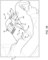
FIGS. 1A and1B illustrate a urinary relief system, in accordance with various embodiments. -
FIG. 2 illustrates a functional diagram of a urinary relief system, in accordance with various embodiments. -
FIGS. 3A, 3B, 3C, and 3D illustrate an integrated pressure regulator and ejector pump, in accordance with various embodiments. -
FIG. 4 illustrates an integrated pressure regulator and ejector pump, in accordance with various embodiments. -
FIG. 5 illustrates an integrated pressure regulator and ejector pump and modular valve housings connected to pressurized gas sources, in accordance with various embodiments. -
FIGS. 6A and 6B illustrate a modular integrated pressure regulator and ejector pump and modular valve housings connected to pressurized gas sources within a housing, in accordance with various embodiments. - The following detailed description of various embodiments herein makes reference to the accompanying drawings, which show various embodiments by way of illustration. While these various embodiments are described in sufficient detail to enable those skilled in the art to practice the disclosure, it should be understood that other embodiments may be realized and that changes may be made without departing from the scope of the disclosure. Thus, the detailed description herein is presented for purposes of illustration only and not of limitation. The steps recited in any of the method or process descriptions may be executed in any order and are not necessarily limited to the order presented. Furthermore, any reference to singular includes plural embodiments, and any reference to more than one component or step may include a singular embodiment or step. Also, any reference to attached, fixed, connected, or the like may include permanent, removable, temporary, partial, full or any other possible attachment option. Additionally, any reference to without contact (or similar phrases) may also include reduced contact or minimal contact. It should also be understood that unless specifically stated otherwise, references to "a," "an" or "the" may include one or more than one and that reference to an item in the singular may also include the item in the plural. Further, all ranges may include upper and lower values and all ranges and ratio limits disclosed herein may be combined.
- Disclosed herein, in various embodiments, is a urinary relief system including a human interface, a storage unit, and a control unit. The human interface is configured to collect and pass a liquid (e.g., urine) from a user (e.g., a pilot) to the storage unit. In various embodiments, the human interface may be designed to be worn under clothing (e.g., flight suit) and close to the body of the user and for prolonged periods of time.. In various embodiments, the human interface may be fluidly coupled to the storage unit by a hose and, in various embodiments, a quick connector coupling. The storage unit is configured to collect and store the liquid (e.g., urine). In various embodiments, the storage unit includes an absorbent material configured to store the liquid in a more viscous form, which may less prone to leakage. The various embodiments, the storage unit includes an input fluidly coupled to the human interface device and an output fluidly coupled to the control unit. In various embodiments, the output includes a liquid restrictor so that little to no liquid is passed to the control unit. In various embodiments, the storage unit and the control unit may be coupled by a hose and, in various embodiments, a quick connector coupling.
- In various embodiments, the control unit includes an ejector head having an integrated pressure regulator and ejector pump. In various embodiments, the control unit includes an ejector head housing, one or more control heads that are removably coupled to each other, a pressurized gas source (e.g., CO2) coupled to each pump housing, and, in various embodiments, a housing to protect the pressurized gas sources. In various embodiments, the control unit includes one or more air ejector pumps driven by one or more CO2 cartridges. In various embodiments, the control unit further includes one or more pressure regulators between the CO2 cartridges and the one or more ejector pumps. In various embodiments, the control unit includes a single housing that encloses the one or more ejector pumps, the one or more pressure regulators, and the one or more CO2 cartridges. In various embodiments, the control heads include couplings to allow multiple control heads to be coupled together to increase the capacity of the control unit.
- In various embodiments, the control unit provides suction to draw the liquid (e.g., urine) from the human interface into the storage unit. In various embodiments, the one or more pressure regulators reduces the working pressure of the control unit by up to 30 times the pressure of each CO2 cartridge. In various embodiments, the reduction in pressure may result in an increase to operation run time of the urinary relief system. In various embodiments, the size of the control unit is reduced by integrating the pressure regulator and the ejector into a single ejector head unit. The control until described herein in its various embodiments may provide a compact design, an extended performance time, a modular control unit, and/or lower cost of fabrication.
- Referring to
FIGS. 1A and1B , aurinary relief system 100 for use by a pilot 102 (e.g., a female pilot) is illustrated, in accordance with various embodiments.Urinary relief system 100 includes ahuman interface device 104, astorage unit 106, and acontrol unit 108.Human interface device 104 is configured to be positioned under the clothing (e.g., flight suit, underwear, pants, etc.) and immediately adjacent the body ofpilot 102 for use in flight. That is, between the body and clothing ofpilot 102 whenpilot 102 is in a seated position. In various embodiments,human interface device 104 may form a seal with the body ofpilot 102.Human interface device 104 may be any size and/or shape conducive for placement under the clothing ofpilot 102 and for collecting the liquid (e.g., urine) while in place.Human interface device 104 includes acollection portion 104a and anoutlet port 104b. -
Storage unit 106 includes astorage inlet port 106a and astorage outlet port 106b.Outlet port 104b ofhuman interface device 104 is connected tostorage inlet port 106a ofstorage unit 106 by aninlet hose 110 andstorage outlet port 106b ofstorage unit 106 is connected to controlunit 108 by anoutlet hose 112. In various embodiments,storage unit 106 may be disposable. In various embodiments,control unit 108 and/orstorage unit 106 may be secured to pilot 102 (e.g., secured to a leg) by one ormore straps 114.Storage unit 106 is configured to receive and trap liquid (e.g., urine) received fromstorage inlet port 106a and not allow the liquid to exit throughstorage outlet port 106b. -
Control unit 108 creates a motive force that draws the liquid (e.g., urine) fromhuman interface device 104 and intostorage unit 106. Air may be drawn, along with the liquid, intostorage unit 106 by the vacuum created bycontrol unit 108. In various embodiments,storage unit 106 includes a filter, or flow restrictor, which allows the air to exitstorage unit 106 throughstorage outlet port 106b and keep the liquid secured instorage unit 106. In various embodiments,control unit 108 provides the motive force by creating a vacuum to draw the liquid fromhuman interface device 104 tostorage unit 106. - Referring now to
FIG. 2 , a functional diagram 200 of a urinary relief system is illustrated, in accordance with various embodiments. Functional diagram 200 may be an example ofurinary relief system 100 described above with respect toFIGS. 1A and1B . Functional diagram 200 includes acollection device 204, astorage device 206, and acontrol device 208. In various embodiments,collection device 204,storage device 206, andcontrol device 208 may be examples ofhuman interface device 104,storage unit 106, andcontrol unit 108, respectively, described above with respect toFIGS. 1A and1B . -
Collection device 204 is configured to collect a liquid 205 (e.g., urine) from a user (e.g., pilot 102).Collection device 204 has anoutlet port 204a,storage device 206 has astorage inlet port 206a and astorage outlet port 206b, andcontrol device 208 has acontrol inlet port 208a and acontrol outlet port 208b.Outlet port 204a ofcollection device 204 is configured to transfer the collected liquid fromcollection device 204 tostorage device 206.Outlet port 204a ofcollection device 204 is connected tostorage inlet port 206a ofstorage device 206.Storage outlet port 206b ofstorage device 206 is connected to controlinlet port 208a ofcontrol device 208. In various embodiments, a hose, or tube, may be used to make the connection between outlet and inlet ports. In various embodiments, there is a firstquick connector interface 212 betweencollection device 204 andstorage device 206 that allows for quick and simple attachment and detachment of a hose, or tube. In various embodiments, there is a second quick connector interface 214 betweenstorage device 206 andcontrol device 208 that allows for quick and simple attachment and detachment the hose, or tube. In various embodiments, a filter, or flowrestrictor 210, is connected tostorage outlet port 206b ofstorage device 206. Flow restrictor 210 prevents liquid (e.g., urine) from passing to controldevice 208 while allowing air to pass to controldevice 208. -
Control device 208 includes anejector head 220 and apressurized gas supply 222.Ejector head 220 includes houses controlinlet port 208a,control outlet port 208b, anejector 224, and apressure regulator 226.Ejector 224 is coupled topressure regulator 226,control inlet port 208a, andcontrol outlet port 208b.Pressurized gas supply 222 includes afirst valve 228a, asecond valve 228b, athird valve 228c, a first CO2 cartridge 230a, a second CO2 cartridge 230b, and a third CO2 cartridge 230c. First CO2 cartridge 230a is coupled tofirst valve 228a, second CO2 cartridge 230b is coupled tosecond valve 228b, and third CO2 cartridge 230c is coupled tothird valve 228c.First valve 228a,second valve 228b, andthird valve 228c are connected in parallel topressure regulator 226 by ahigh pressure line 232. That is, eachvalve high pressure line 232 that is in turn connected topressure regulator 226. While the description herein uses CO2 cartridges, it should be appreciated that any suitable pressurized gas container may be used. - Each CO2 cartridge 230a, 230b, 230c is sealed and connected to the
corresponding valve valve first valve 228a is configured to puncture the seal of first CO2 cartridge 230a, in response to an input, allowing the compressed air in first CO2 cartridge 230a to pass throughfirst valve 228a, intohigh pressure line 232, and topressure regulator 226.Second valve 228b is configured to puncture the seal of second CO2 cartridge 230b, in response to an input, allowing the compressed air in second CO2 cartridge 230b to pass throughsecond valve 228b, intohigh pressure line 232, and topressure regulator 226.Third valve 228c is configured to puncture the seal of third CO2 cartridge 230c, in response to an input, allowing the compressed air in third CO2 cartridge 230c to pass throughthird valve 228c, intohigh pressure line 232, and topressure regulator 226. -
Pressure regulator 226 has ahigh pressure inlet 226a and a reduced pressure outlet 226b.Pressure regulator 226 receives the high pressure air fromhigh pressure line 232 athigh pressure inlet 226a, reduces the pressure of the air (e.g., CO2), and outputs the air at a reduced pressure from reduced pressure outlet 226b. The pressure of the air at reduced pressure outlet 226b is about 15 times to about 45 times less than the pressure of the air received athigh pressure inlet 226a. In various embodiments, the pressure of the air at reduced pressure outlet 226b is about 25 times to about 35 times less than the pressure of the air received athigh pressure inlet 226a. Reducing the pressure of the air bypressure regulator 226 slows the release of the pressurized air (e.g., CO2) and therefore extends the lifespan of each CO2 cartridge 230a, 266b, 226c. Adjusting the release pressure (e.g., air pressure at reduced pressure outlet 226b) either up or down may decrease or increase, respectively, the effective lifespan of each CO2 cartridge 230a, 230b, 230c. -
Ejector 224 has anair inlet 224a, anair outlet 224b, and avacuum port 224c.Air inlet 224a ofejector 224 is connected to reduced pressure outlet 226b ofpressure regulator 226.Air outlet 224b is connected to controloutlet port 208b which is open to the environment (e.g., cockpit, cabin, etc.).Vacuum port 224c is connected tostorage outlet port 206b ofstorage device 206.Ejector 224 receives pressurized air atair inlet 224a and passes the pressurized air toair outlet 224b to create a vacuum atvacuum port 224c. The vacuum creates a motive force that passes throughstorage device 206 tocollection device 204 and draws, or sucks, air and liquid (e.g., urine) fromcollection device 204 intostorage device 206. A combination of the materials insidestorage device 206 and flowrestrictor 210 trap and prevent the liquid from being pulled toejector head 220, and more specifically, intoejector 224. Instead, air present in the system is drawn by the vacuum created byejector 224, continuing to pull liquid fromcollection device 204. - Referring now to
FIGS. 3A-3D , acontrol unit 300 is illustrated, in accordance with various embodiments.Control unit 300 may be an example ofcontrol device 208 described above with respect toFIG. 2 .Control unit 300 includes similar components to those describe above with respect to controldevice 208 inFIG. 2 , including anejector head 320, a pressurized gas supply 322, acontrol inlet port 308a, acontrol outlet port 308b, anejector 324, apressure regulator 326, afirst valve 328a, a second valve 328b, a third valve 328c, a first CO2 cartridge 330a, a second CO2 cartridge 330b, and a third CO2 cartridge 330c. These components are described above with respect toFIG. 2 , the description of which may not be repeated below.Control unit 300 further includes ahousing 302, afast connector 304, afourth valve 328d, a fourth CO2 cartridge 330c, afirst toggle 334a, asecond toggle 334b, athird toggle 334b, afourth toggle 334d. -
Housing 302 includes anupper portion 302a and alower portion 302b that may be detachable fromupper portion 302a.Upper portion 302ahouses ejector head 320 includingcontrol inlet port 308a,control outlet port 308b,ejector 324, andpressure regulator 326.Lower portion 302b enclosesvalves 328a-328d and CO2 cartridges 330a-330d. In various embodiments,lower portion 302b may be coupled toupper portion 302a using snaps, buttons, friction retainers, or press fitting, among others. In various embodiments,lower portion 302b may be coupled toupper portion 302a by sliding a feature oflower portion 302b into a feature ofupper portion 302a, such as rails for example. Ahigh pressure line 332 connectsvalves 328a-328d toejector head 320, and more specifically, topressure regulator 326.Toggles 334a-334d are coupled toupper portion 302a and are configured to engagevalves 328a-328d individually. In various embodiments,housing 302 may further includefinger guards 306 disposed between and separating each of thetoggles 334a-334d. -
Fast connector 304 includes afirst port 304a and asecond port 304b.Fast connector 304 is removable fromhousing 302 and is configured to quickly attach to and detach fromhousing 302 at attachment point 336. In various embodiments,fast connector 304 may include grooves that interface withhousing 302 to guidefast connector 304 securefast connector 304 into place. Whenfast connector 304 is attached tohousing 302,first port 304a is aligned withcontrol inlet port 308a andsecond port 304b is aligned withcontrol outlet port 308b. A hose, tube, or other connector may be connected tofirst port 304a at one end a storage device (e.g., storage device 206) at an opposite end. In various embodiments, a hose, tube, or other connector, may be connected tosecond port 304b to control how air is vented fromcontrol unit 300. - Each
toggle 334a-334d is configured to engage acorresponding valve 328a-328d. Eachtoggle 334a-334d is configured to toggle between an engaged position and a disengaged position. Eachtoggle 334a-334d is initialized in the disengaged position (e.g.,first toggle 334a andsecond toggle 334b). Eachtoggle 334a-334d may be individually flipped, or switched, to the engaged position (e.g.,third toggle 334c andfourth toggle 334d).Toggles 334a-334d are configured to provide tactile and/or audible feedback to the user (e.g., pilot 102), such as a click, allowing the user to know the toggle was engaged without looking. Eachtoggle 334a-334d has a length L1 that allows the user (e.g., pilot 102) to feel and activate, or switch, toggle 334a-334d without looking. Length L1 may be about 0.25 inches (about 0.635 centimeter) to about 1 inch (about 2.54 centimeters), and more specifically, about .4 inches (about 1.02 centimeters) to about .6 inches (about 1.52 centimeters). Flippingtoggle 334a-334d from the disengaged position to the engage position opens thecorresponding valve 328a-328d. - Opening each
valve 328a-328d punctures the corresponding CO2 cartridge 330a-330d, releasing the pressurized air and activatingcontrol unit 300. In various embodiments,valves 328a-328d may be configured to open and stay opened, allowing all, or substantially all, the gas of each CO2 cartridge 330a-330d to exit. In various embodiments,valves 328a-328d may be configured to open and close, allowing the user (e.g., pilot 102) to the control the gas used from each CO2 cartridge 330a-330d, allowing for using one or more CO2 cartridges 330a-330d more than once. Typically, one CO2 cartridge 330a-330d is used at a time. However, in various embodiments, more than onevalve 328a-328d may be opened at one time to increase the pressure and/or the mass flow rate of the pressurized CO2. -
Lower portion 302b may be removed fromupper portion 302a to remove and replace spent CO2 cartridges 330a-330d. After removinglower portion 302b, each CO2 cartridge 330a-330d is removed and replaced. Eachtoggle 334a-334d is moved, or switched, back to the disengaged position.Lower portion 302b may then be reconnected toupper portion 302a. In various embodiments, this may be accomplished whilecontrol unit 300 is connected to a storage device (e.g., storage device 206). - Referring now to
FIG. 4 , acontrol unit 400 is illustrated, in accordance with various embodiments.Control unit 400 may be an example ofcontrol device 208 described above with respect toFIG. 2 .Control unit 400 includes similar components to those describe above with respect to controlunit 300 inFIG. 3 , including anejector head 420, apressurized gas supply 422, acontrol inlet port 408a, a control outlet port 408b, anejector 424, apressure regulator 426, afirst valve 428a, asecond valve 428b, athird valve 428c, afourth valve 428d, a first CO2 cartridge 430a, a second CO2 cartridge 430b, and a third CO2 cartridge 430c, a fourth CO2 cartridge 430d, afirst toggle 434a, asecond toggle 434b, athird toggle 434c, afourth toggle 434d, and afast connector 404. These components are described above with respect toFIG. 3 , the description of which may not be repeated below.Control unit 400 further includes anejector head housing 402, afirst cartridge housing 410a, asecond cartridge housing 410b, athird cartridge housing 410c, and afourth cartridge housing 410d. -
Ejector head housing 402 enclosescontrol inlet port 408a, control outlet port 408b, a controlhigh pressure port 408c,ejector 424, andpressure regulator 426.Fast connector 404 is removably connected toejector head housing 402 overcontrol inlet port 408a and control inlet port 408b.Fast connector 404 has afirst port 404a and asecond port 404b. Whenfast connector 404 is connected toejector head housing 402,first port 404a is in communication withcontrol inlet port 408a andsecond port 404b is in communication with control inlet port 408b. -
Ejector head housing 402 has a height H1 (e.g., in the y-direction) and a width W1 (e.g., in the x-direction). Height H1 is about 3.5 inches (about 8.89 centimeters) to about 6 inches (about 15.2 centimeters), and more specifically, about 4 inches (about 10.2 centimeters) to about 5 inches (about 12.7 centimeters). Width W1 is about 1 inch (about 2.54 centimeters) to about 2.5 inches (about 6.35 centimeters), and more specifically, about 1.25 inches (about 3.17 centimeters) to about 2 inches (about 5.08 centimeters). - Each
cartridge housing 410a-410d encloses acorresponding valve 428a-428d and a corresponding CO2 cartridge 430a-430d. Eachcartridge housing 410a-410d further includes acorresponding toggle 434a-434d configured to engage thecorresponding valve 428a-428d.Cartridge housing 410a-410d has a height H2 (e.g., in the y-direction) and a width W2 (e.g., in the x-direction). Height H2 is about 4 inches (about 10.2 centimeters) to about 7 inches (about 17.8 centimeters), and more specifically, about 4.5 inches (about 11.4 centimeters) to about 6 inches (about 15.2 centimeters). Width W2 is about 1 inch (about 2.54 centimeters) to about 2 inches (about 5.08 centimeters), and more specifically, about 1.25 inches (about 3.17 centimeters) to about 1.75 inches (about 4.44 centimeters). - CO2 cartridge 430a-430d is sized to fit within
cartridge housing 410a-410d having a total height H3, a body height H4, a neck height H5, a body width W3, and a neck width W4. Height H3 is about 3.75 inches (about 9.53 centimeters) to about 5.25 inches (about 13.3 centimeters) and more specifically, about 3.5 inches (about 8.89 centimeters). Body height H4 is about 3.5 inches (about 8.89 centimeters) to about 4.5 inches (about 11.4 centimeters) and more specifically, about 3 inches (about 7.62 centimeters). Neck height H5 is about 0.25 inches (about 0.635 centimeter) to about 0.75 inches (about 1.9 centimeters), and more specifically, about 0.5 inches (about 1.27 centimeters). Body width W3 is about 0.4 inches (about 1.02 centimeters) to about 1 inch (about 2.54 centimeters), and more specifically, about 0.6 inches (about 1.52 centimeters) to about 0.8 inches (about 2.03 centimeters). Neck width W4 is about 0.25 inches (about 0.635 centimeter) to about .5 inches (about 1.27 centimeters), and more specifically, about 0.375 inches (about 0.952 centimeter). -
Cartridge housing 410a-410d further includes afirst connector 412 and asecond connector 414.First connector 412 of eachcartridge housing 410a-410d is configured to engagesecond connector 414 ofejector head housing 402 and/orcartridge housing 410a-410d. In various embodiments,first connector 412 may be press fit ontosecond connector 414. In various embodiments,first connector 412 may slide ontosecond connector 414. In various embodiments, an O-ring may be used to provide an air tight seal betweenfirst connector 412 andsecond connector 414. Connections betweenfirst connector 412 andsecond connector 414 forms a high pressure line 432. In various embodiments, high pressure line 432 may be a conduit, a tube, a passageway, or an opening, among others. - This configuration allows
control unit 400 to be modular. That is,ejector head housing 402 may be connected to one ormore cartridge housings 410a-410d. This allows the user (e.g., pilot 102) to attach asmany cartridge housings 410a-410d as will be used during a specific mission. The user may choose different numbers ofcartridge housings 410a-410d for size, weight, and/or number of uses anticipated for a mission. Additionally, this allows for reloadingcontrol unit 400 by swappingcartridge housings 410a-410d. - Referring now to
FIG. 5 , amodular control unit 500 is illustrated in accordance with various embodiments.Modular control unit 500 includes similar components to controlunit 400 described above inFIG. 4 including anejector head housing 502, afast connector 504, afirst port 504a, asecond port 504b, afirst connector 512, asecond connector 514, anejector head 520, a firstpressurized gas source 530a, a secondpressurized gas source 530b, and a thirdpressurized gas source 530c, a fourthpressurized gas source 530d, afirst toggle 534a, asecond toggle 534b, athird toggle 534c, and afourth toggle 534d, among others which may not be illustrated, descriptions of which may not be repeated below.Modular control unit 500 further includes afirst control head 540a, asecond control head 540b, athird control head 540c, and afourth control head 540d.First control head 540a includes a first valve (e.g.,first valve 428a),second control head 540b includes a second valve (e.g.,second valve 428b),third control head 540c includes a third valve (e.g.,third valve 428c), andfourth control head 540d includes a fourth valve (e.g.,fourth valve 428d). - As previously discussed,
pressurized gas sources 530a-530d may be any pressurized gas source, including pressurized air cartridge, CO2 cartridge, and/or nitrogen cartridge, among others.Pressurized gas sources 530a-530d each include a seal to contain the gas therein and prevent from leaking out. The gas contained in eachpressurized gas source 530a-530d may be expelled from the respectivepressurized gas source 530a-530d in response to the seal being broken, or opened. For simplicity,pressurized gas sources 530a-530d will be referred to as CO2 cartridges 530a-530d below. Each CO2 cartridge 530a-530d may include a threaded neck, such as threadedneck 542 illustrated on fourth CO2 cartridge 530d. Eachcontrol head 540a-540d may include a complimentary pressurized gas source input 544 (e.g., a threaded opening) that is configured to receive threadedneck 542 of CO2 cartridge 530d. In various embodiments, CO2 cartridges 530a-530d may be configured to be press fit intocontrol heads 540a-540d. That is, CO2 cartridge 530d may include an indentation, and in various embodiments, an O-ring, instead of threading around the neck (e.g., threaded neck 542) and pressurizedgas source input 544 offourth control head 540d may be configured to receive and seat fourth CO2 cartridge 530d accordingly. - Each CO2 cartridge 530a-530d, after being coupled to a
respective control head 540a-540d, is in fluid communication with a valve located within eachcontrol head 540a-540d. Each valve is in fluid communication with an output connector (e.g., first connector 512) to allow the pressurized gas to flow from CO2 cartridge (e.g., CO2 cartridge 530b) toejector head 520 through the output connector. - Each
control head 540a-540d further includes an input connector (e.g., second connector 514) that is configured to receive the output connector of anadjacent control head 540a-540d and pass the pressurized gas from the adjacent control head toejector head 520. In various embodiments, the flow pressurized gas from the input connector to the output connector bypasses the valve withincontrol head 540a-540d. - Each
toggle 534a-534d is coupled to arespective control head 540a-540d. As previously discussed, each toggle (e.g.,toggle 534d) is rotational coupled to a respective control head (e.g.,fourth control head 540d).Toggle 534d may rotate from a closed, or off, position to an open, or on, position and in so doing puncture the seal of CO2 cartridge 530d. In various embodiments, the seal may be punctured, or opened, in response to being inserted intofourth control head 540d. The gas is then released from CO2 cartridge 530d and intofourth control head 540d where the valve controls and directs the pressurized CO2 towardejector head 520. - Each output connector (e.g., first connector 512) is configured to mate with, or be coupled to, a respective input connector (e.g., second connector 514) on an adjacent control head. In various embodiments, the input connector and output connector may be press fit together to form a seal and secure a first control head (e.g.,
first control head 540a) to a second control head (e.g.,second control head 540b). In various embodiments, the connection between control heads (e.g.,first control head 540a andsecond control 540b) may be secured using a threaded connection such as, for example, a bolt and nut configuration or a bolt and insert configuration, among others. In various embodiments, there may be a snap coupled around the input connector and output connector that allows the first control head (e.g.,first control head 540a) to snap into the second control head (e.g.,second control head 540b). In various embodiments, one or more O-rings may be utilized to improve the seal between the adjoined control heads (e.g.,first control head 540a andsecond control head 540b). Additionally, or in the alternative, the O-rings may, in various embodiments, act as a shock absorber or cushion to provide a better connection between the adjoined control heads (e.g.,first control head 540a andsecond control head 540b). - In various embodiments, the adjacent control heads (e.g.,
first control head 540a andsecond control head 540b) may be slidably coupled together. In various embodiments, each control head (e.g.,first control head 540a andsecond control head 540b) may include a tongue and groove configuration that is configured to slide into place and secure adjoining control heads (e.g.,first control head 540a andsecond control head 540b) to each other. In various embodiments, each control head may include a set of rails that are configured to interlock and secure the adjoining control heads (e.g.,first control head 540a andsecond control head 540b) to each other. In various embodiments, a latch may be included to prevent the control heads (e.g.,first control head 540a andsecond control head 540b) from separating after being joined. - Referring now to
FIGS. 6A and 6B , amodular control unit 600 including a housing is illustrated, in accordance with various embodiments.Modular control unit 600 includes similar components tomodular control unit 500 described above inFIG. 5 including anejector head housing 602, afast connector 604, afirst port 604a, asecond port 604b, asecond connector 614, anejector head 620, a firstpressurized gas source 630a, a secondpressurized gas source 630b, and a thirdpressurized gas source 630c, a fourthpressurized gas source 630d, afirst toggle 634a, asecond toggle 634b, athird toggle 634c, and afourth toggle 634d, afirst control head 640a, asecond control head 640b, athird control head 640c, and afourth control head 640d, among others which may not be illustrated, descriptions of which may not be repeated below.Modular control unit 600 further includes a housing to secure andsupport control heads 640a-640d andpressurized gas sources 630a-630d.FIG. 6A illustratesmodular control unit 600 including ahousing 650 for fourpressurized gas sources 630a-630d.FIG. 6B illustratesmodular control unit 600 including amodular housing 652 for a singlepressurized gas source 630a. -
Housing 650 includes a first end 650a and a second end 650b and encloses and securespressurized gas sources 630a-630d toejector head 620. In various embodiments,housing 650 may be a single, monolithic component configured to house one or morepressurized gas sources 630a-630d. In various embodiments, first end 650a ofhousing 650 is configured to engageejector head 620, and in various embodiments, secured toejector head 620. In various embodiment, second end 650b is configured to engagesecond connector 614, and in various embodiments, be secured tosecond connector 614. is configured to couple toejector head 620 at a first end and tosecond connector 614 at a second end. - In various embodiments,
modular housing 652 may be configured to house a single pressurized gas source (e.g., firstpressurized gas source 630a).Modular housing 652 may be configured to engage and/or interlock with an adjacentmodular housing 652. Modular housing has a first end 652a and a second end 652b. First end 652a of a firstmodular housing 652 is configured to engageejector head 620 and/or second end 652b of a secondmodular housing 652. That is, eachmodular housing 652 is configured to house a single pressurized gas source (e.g., firstpressurized gas source 630a) and is further configured to be secured to an adjacentmodular housing 652. - As disclosed herein,
housing 650, ormodular housing 652, provide additional support and security forpressurized gas sources 630a-630d. The additional support prevents one or morepressurized gas sources 630a-630d from separating from arespective control head 640a-640d and breaking open the one or morepressurized gas sources 630a-630d.Housing 650, andmodular housing 652, provide added comfort of use and ease of transport by enclosing the individual components ofmodular control unit 600. Furthermore,housing 650 andmodular housing 652 may, in various embodiments, provide a thermal barrier between the pressurized gas source and the user ofmodular control unit 600. Accordingly,housing 650 and/ormodular housing 652 may, in various embodiments, further include an insulator such as rubber, silicone, cork, wood, plastic, or a cloth material, among others. - Benefits, other advantages, and solutions to problems have been described herein with regard to specific embodiments. Furthermore, the connecting lines shown in the various figures contained herein are intended to represent exemplary functional relationships and/or physical couplings between the various elements. It should be noted that many alternative or additional functional relationships or physical connections may be present in a practical system. However, the benefits, advantages, solutions to problems, and any elements that may cause any benefit, advantage, or solution to occur or become more pronounced are not to be construed as critical, required, or essential features or elements of the disclosure. The scope of the disclosure is accordingly to be limited by nothing other than the appended claims, in which reference to an element in the singular is not intended to mean "one and only one" unless explicitly so stated, but rather "one or more." Moreover, where a phrase similar to "at least one of A, B, or C" is used in the claims, it is intended that the phrase be interpreted to mean that A alone may be present in an embodiment, B alone may be present in an embodiment, C alone may be present in an embodiment, or that any combination of the elements A, Band C may be present in a single embodiment; for example, A and B, A and C, B and C, or A and B and C. Different cross-hatching is used throughout the figures to denote different parts but not necessarily to denote the same or different materials.
- Systems, methods, and apparatus are provided herein. In the detailed description herein, references to "one embodiment," "an embodiment," "various embodiments," etc., indicate that the embodiment described may include a particular feature, structure, or characteristic, but every embodiment may not necessarily include the particular feature, structure, or characteristic. Moreover, such phrases are not necessarily referring to the same embodiment. Further, when a particular feature, structure, or characteristic is described in connection with an embodiment, it is submitted that it is within the knowledge of one skilled in the art to affect such feature, structure, or characteristic in connection with other embodiments whether or not explicitly described. After reading the description, it will be apparent to one skilled in the relevant art(s) how to implement the disclosure in alternative embodiments.
- Numbers, percentages, or other values stated herein are intended to include that value, and also other values that are about or approximately equal to the stated value, as would be appreciated by one of ordinary skill in the art encompassed by various embodiments of the present disclosure. A stated value should therefore be interpreted broadly enough to encompass values that are at least close enough to the stated value to perform a desired function or achieve a desired result. The stated values include at least the variation to be expected in a suitable industrial process, and may include values that are within 5% of a stated value. Additionally, the terms "substantially," "about" or "approximately" as used herein represent an amount close to the stated amount that still performs a desired function or achieves a desired result. For example, the term "substantially," "about" or "approximately" may refer to an amount that is within 5% of a stated amount or value.
- Furthermore, no element, component, or method step in the present disclosure is intended to be dedicated to the public regardless of whether the element, component, or method step is explicitly recited in the claims. As used herein, the terms "comprises," "comprising," or any other variation thereof, are intended to cover a non-exclusive inclusion, such that a process, method, article, or apparatus that comprises a list of elements does not include only those elements but may include other elements not expressly listed or inherent to such process, method, article, or apparatus.
- Finally, it should be understood that any of the above-described concepts can be used alone or in combination with any or all of the other above-described concepts. Although various embodiments have been disclosed and described, one of ordinary skill in this art would recognize that certain modifications would come within the scope of this disclosure. Accordingly, the description is not intended to be exhaustive or to limit the principles described or illustrated herein to any precise form. Many modifications and variations are possible in light of the above teaching.
Claims (15)
- A control head (540a-540d) for a modular control unit of a urinary relief system, comprising:a pressurized gas source input;a toggle (534a-534d) configured to activate a pressurized gas source (530a-530d) coupled to the pressurized gas source input;a first connector (512) fluidly coupled to the pressurized gas source input and configured to allow a first gas from the pressurized gas source input to flow through the control head; anda second connector (514) fluidly coupled to the first connector and configured to allow a second gas to pass through the control head.
- The control head of the modular control unit of the urinary relief system of claim 1, further comprising:
a valve coupled to the pressurized gas source input, wherein the first connector (512) is fluidly coupled to the pressurized gas source input through the valve; and optionally wherein the toggle (534a-534d) is further configured to open the valve. - The control head of the modular control unit of the urinary relief system of claim 1 or 2, further comprising:a first connector on the first connector (512); anda second connector on the second connector (514), the second connector configured to engage the first connector.
- The control head of the modular control unit of the urinary relief system of claim 3, wherein the first connector (512) includes a first rail and the second connector (514) includes a second rail that is configured to engage the first rail; orwherein the first connector includes a first threading and the second connector includes a second threading that is configured to engage the first threading; orwherein the first connector includes a first snap connector and the second connector includes a second snap connector that is configured to engage the first snap connector.
- A modular control unit for a urinary relief system, comprising:a first pressurized gas source (530a);a pressure regulator (226) configured to regulate a pressure of the first pressurized gas source;an ejector (224) coupled to the pressure regulator and an output;an ejector head housing the pressure regulator and the ejector;a first control head (540a) coupled to the ejector head housing, the first control head including:a first pressurized gas source input configured to receive the first pressurized gas source;a first toggle (534a) configured to activate the first pressurized gas source;a first connector (512) fluidly coupled to the first pressurized gas source input and fluidly coupled to the ejector head housing, the first connector configured to allow a first gas from the first pressurized gas source input to flow through the first control head and into the ejector head housing; anda second connector (514) fluidly coupled to the first connector and configured to allow a second gas to pass through the first control head.
- The modular control unit for the urinary relief system of claim 5, further comprising:a second pressurized gas source (530b); anda second control head (540b) coupled to the first control head (540a), the second control head including:a second pressurized gas source input configured to receive the second pressurized gas source;a second toggle (534b) configured to activate the second pressurized gas source; anda first connector fluidly coupled to the second pressurized gas source input and fluidly coupled to the first control head, the first connector configured to allow the second gas from the second pressurized gas source input to flow through the second control head and into the first control head through the second connector of the first control head.
- The modular control unit for the urinary relief system of claim 6, wherein the second connector (514) of the first control head is configured to receive the first connector of the second control head.
- The modular control unit for the urinary relief system of claim 7, wherein the second connector (514) of the first control head includes a first rail and the first connector of the second control head includes a second rail that is configured to engage the first rail.
- The modular control unit for the urinary relief system of claim 6, 7 or 8, further comprising:a housing coupled to the ejector head housing and the second control head, the housing being configured to house the first pressurized gas source (530a) and the second pressurized gas source (530b);
orfurther comprising:a first housing coupled to the ejector head housing and the first control head (540a), the first housing configured to house the first pressurized gas source (530a); anda second housing coupled to the first housing and the second control head (540b), the second housing configured to house the second pressurized gas source (530b). - The modular control unit for the urinary relief system of any of claims 5 to 9, wherein the first control head (540a) further comprises:
a first valve coupled to the first pressurized gas source input, wherein the first connector (512) is fluidly coupled to the first pressurized gas source input through the first valve, wherein the first toggle (534a) is further configured to open the first valve. - A urinary relief system, comprising:a human interface device (104);a storage device (106) coupled to the human interface device; anda modular control unit (108) coupled to the storage device, the modular control unit including:a first pressurized gas source (530a);a pressure regulator (226) configured to regulate a pressure of the first pressurized gas source;an ejector (224) coupled to the pressure regulator and an output;an ejector head housing the pressure regulator and the ejector;a first control head (540a) coupled to the ejector head housing, the first control head including:a first pressurized gas source input configured to receive the first pressurized gas source;a first toggle (534a) configured to activate the first pressurized gas source;a first connector (512) fluidly coupled to the first pressurized gas source input and fluidly coupled to the ejector head housing, the first connector configured to allow a first gas from the first pressurized gas source input to flow through the first control head and into the ejector head housing; anda second connector (514) fluidly coupled to the first connector and configured to allow a second gas to pass through the first control head.
- The urinary relief system of claim 11, wherein the modular control unit (108) further comprises:a second pressurized gas source (530b); anda second control head (540b) coupled to the first control head (540a), the second control head including:a second pressurized gas source input configured to receive the second pressurized gas source (530b);a second toggle (534b) configured to activate the second pressurized gas source; anda first connector fluidly coupled to the second pressurized gas source input and fluidly coupled to the first control head, the first connector configured to allow the second gas from the second pressurized gas source input to flow through the second control head and into the first control head through the second connector (514) of the first control head.
- The urinary relief system of claim 12, wherein the second connector (514) of the first control head is configured to receive the first connector of the second control head.
- The urinary relief system of claim 12 or 13,
further comprising:a housing coupled to the ejector head housing and the second control head (540b), the housing being configured to house the first pressurized gas source (530a) and the second pressurized gas source (530b); orfurther comprising:a first housing coupled to the ejector head housing and the first control head (540a), the first housing configured to house the first pressurized gas source (530a); anda second housing coupled to the first housing and the second control head (540b), the second housing configured to house the second pressurized gas source (530b). - The urinary relief system of claim 12, 13 or 14, wherein the first control head (540a) is slidably coupled to the second control head (540b).
Applications Claiming Priority (1)
| Application Number | Priority Date | Filing Date | Title |
|---|---|---|---|
| US18/364,383 US20250041101A1 (en) | 2023-08-02 | 2023-08-02 | Modular suction unit for a urinary relief system |
Publications (2)
| Publication Number | Publication Date |
|---|---|
| EP4501289A1 true EP4501289A1 (en) | 2025-02-05 |
| EP4501289B1 EP4501289B1 (en) | 2026-01-14 |
Family
ID=91924518
Family Applications (1)
| Application Number | Title | Priority Date | Filing Date |
|---|---|---|---|
| EP24187850.3A Active EP4501289B1 (en) | 2023-08-02 | 2024-07-10 | Modular suction unit for a urinary relief system |
Country Status (2)
| Country | Link |
|---|---|
| US (1) | US20250041101A1 (en) |
| EP (1) | EP4501289B1 (en) |
Citations (5)
| Publication number | Priority date | Publication date | Assignee | Title |
|---|---|---|---|---|
| US20040176746A1 (en) * | 2003-03-03 | 2004-09-09 | Arthur Esguerra Forral | Urine collection system for males utilizing a flexible external catheter and vacuum assistance |
| US7135012B2 (en) * | 2002-02-26 | 2006-11-14 | Harvie Mark R | Automatic self cleaning bladder relief system |
| US7448288B2 (en) * | 2006-10-12 | 2008-11-11 | Vincent Montefusco | Scent evidence transfer device |
| EP3977967A1 (en) * | 2020-10-02 | 2022-04-06 | B/E Aerospace, Inc. | Urinary relief device |
| EP4431065A1 (en) * | 2023-03-17 | 2024-09-18 | B/E Aerospace, Inc. | Integrated pressure regulator and ejector pump for urinary relief system |
-
2023
- 2023-08-02 US US18/364,383 patent/US20250041101A1/en active Pending
-
2024
- 2024-07-10 EP EP24187850.3A patent/EP4501289B1/en active Active
Patent Citations (5)
| Publication number | Priority date | Publication date | Assignee | Title |
|---|---|---|---|---|
| US7135012B2 (en) * | 2002-02-26 | 2006-11-14 | Harvie Mark R | Automatic self cleaning bladder relief system |
| US20040176746A1 (en) * | 2003-03-03 | 2004-09-09 | Arthur Esguerra Forral | Urine collection system for males utilizing a flexible external catheter and vacuum assistance |
| US7448288B2 (en) * | 2006-10-12 | 2008-11-11 | Vincent Montefusco | Scent evidence transfer device |
| EP3977967A1 (en) * | 2020-10-02 | 2022-04-06 | B/E Aerospace, Inc. | Urinary relief device |
| EP4431065A1 (en) * | 2023-03-17 | 2024-09-18 | B/E Aerospace, Inc. | Integrated pressure regulator and ejector pump for urinary relief system |
Also Published As
| Publication number | Publication date |
|---|---|
| EP4501289B1 (en) | 2026-01-14 |
| US20250041101A1 (en) | 2025-02-06 |
Similar Documents
| Publication | Publication Date | Title |
|---|---|---|
| CA1281876C (en) | Heating of article using shroud to direct gas to selected portions | |
| CA1328387C (en) | Blood recovery system and method | |
| EP4431065A1 (en) | Integrated pressure regulator and ejector pump for urinary relief system | |
| EP4501289B1 (en) | Modular suction unit for a urinary relief system | |
| JP5683554B2 (en) | Apparatus and method for treatment of damaged tissue | |
| CA1280326C (en) | Fast response tubeless vacuum aspiration collection cassette | |
| US20140171889A1 (en) | Multi-function Hand Pump for Medical Use | |
| US20010029955A1 (en) | Convertible patient isolation pod | |
| SE537810C2 (en) | Iv safety catheter unit with seal | |
| WO1996030076A1 (en) | Connector assembly | |
| WO1991017790A1 (en) | Method, apparatus for delivering or withdrawing fluid | |
| US20040176746A1 (en) | Urine collection system for males utilizing a flexible external catheter and vacuum assistance | |
| US8979810B1 (en) | Nasal aspiration systems and related methods | |
| CS211382B2 (en) | Sucction pump | |
| CN102114289A (en) | Automatic gas source switching device | |
| EP3669910A1 (en) | Disposable syringe for use with pneumatic drivers | |
| US20240307214A1 (en) | Human interface device for urinary relief system | |
| CN112263025A (en) | Liquid cooling suit and body cooling system containing the same | |
| EP4431066B1 (en) | Flexible wall storage unit for urinary relief system | |
| AU600915B2 (en) | Fast response tubeless vacuum aspiration collection cassette | |
| CN201603005U (en) | Pressure regulating device of negative pressure suction in air pressurization oxygen cabin | |
| CN214258001U (en) | Liquid cooling clothes and human body cooling system comprising same | |
| US20230312223A1 (en) | Hydration system adapted for use in cbrn environments | |
| BR112015022916B1 (en) | EXhalation VALVE ASSEMBLY AND RESPIRATOR ASSEMBLY | |
| CN215537099U (en) | Negative pressure suction device |
Legal Events
| Date | Code | Title | Description |
|---|---|---|---|
| PUAI | Public reference made under article 153(3) epc to a published international application that has entered the european phase |
Free format text: ORIGINAL CODE: 0009012 |
|
| STAA | Information on the status of an ep patent application or granted ep patent |
Free format text: STATUS: THE APPLICATION HAS BEEN PUBLISHED |
|
| AK | Designated contracting states |
Kind code of ref document: A1 Designated state(s): AL AT BE BG CH CY CZ DE DK EE ES FI FR GB GR HR HU IE IS IT LI LT LU LV MC ME MK MT NL NO PL PT RO RS SE SI SK SM TR |
|
| STAA | Information on the status of an ep patent application or granted ep patent |
Free format text: STATUS: REQUEST FOR EXAMINATION WAS MADE |
|
| GRAP | Despatch of communication of intention to grant a patent |
Free format text: ORIGINAL CODE: EPIDOSNIGR1 |
|
| STAA | Information on the status of an ep patent application or granted ep patent |
Free format text: STATUS: GRANT OF PATENT IS INTENDED |
|
| 17P | Request for examination filed |
Effective date: 20250804 |
|
| INTG | Intention to grant announced |
Effective date: 20250820 |
|
| RIC1 | Information provided on ipc code assigned before grant |
Ipc: A61F 5/44 20060101AFI20250811BHEP Ipc: A61F 5/451 20060101ALI20250811BHEP Ipc: A61F 5/455 20060101ALI20250811BHEP |
|
| GRAS | Grant fee paid |
Free format text: ORIGINAL CODE: EPIDOSNIGR3 |
|
| GRAA | (expected) grant |
Free format text: ORIGINAL CODE: 0009210 |
|
| STAA | Information on the status of an ep patent application or granted ep patent |
Free format text: STATUS: THE PATENT HAS BEEN GRANTED |
|
| AK | Designated contracting states |
Kind code of ref document: B1 Designated state(s): AL AT BE BG CH CY CZ DE DK EE ES FI FR GB GR HR HU IE IS IT LI LT LU LV MC ME MK MT NL NO PL PT RO RS SE SI SK SM TR |
|
| REG | Reference to a national code |
Ref country code: CH Ref legal event code: F10 Free format text: ST27 STATUS EVENT CODE: U-0-0-F10-F00 (AS PROVIDED BY THE NATIONAL OFFICE) Effective date: 20260114 Ref country code: GB Ref legal event code: FG4D |
|
| REG | Reference to a national code |
Ref country code: DE Ref legal event code: R096 Ref document number: 602024002044 Country of ref document: DE |
|
| REG | Reference to a national code |
Ref country code: IE Ref legal event code: FG4D |