EP4501282A1 - Intelligenter sensorartiger mundspüler - Google Patents
Intelligenter sensorartiger mundspüler Download PDFInfo
- Publication number
- EP4501282A1 EP4501282A1 EP23933801.5A EP23933801A EP4501282A1 EP 4501282 A1 EP4501282 A1 EP 4501282A1 EP 23933801 A EP23933801 A EP 23933801A EP 4501282 A1 EP4501282 A1 EP 4501282A1
- Authority
- EP
- European Patent Office
- Prior art keywords
- machine
- sensing
- assembly
- rack
- data line
- Prior art date
- Legal status (The legal status is an assumption and is not a legal conclusion. Google has not performed a legal analysis and makes no representation as to the accuracy of the status listed.)
- Pending
Links
Images

Classifications
-
- A—HUMAN NECESSITIES
- A61—MEDICAL OR VETERINARY SCIENCE; HYGIENE
- A61C—DENTISTRY; APPARATUS OR METHODS FOR ORAL OR DENTAL HYGIENE
- A61C17/00—Devices for cleaning, polishing, rinsing or drying teeth, teeth cavities or prostheses; Saliva removers; Dental appliances for receiving spittle
- A61C17/02—Rinsing or air-blowing devices, e.g. using fluid jets or comprising liquid medication
- A61C17/0202—Hand-pieces
Definitions
- the present disclosure relates to the technical field of oral cleaning, and in particular, to an intelligent sensing dental irrigator.
- the intelligent sensing dental irrigator comprises a body integration rack, a sensing cover assembly, a sensor assembly, a machine-core assembly, and a data transmission assembly.
- the body integration rack has a wiring constraint structure.
- the sensing cover assembly is disposed above the body integration rack.
- the sensor assembly is disposed on the sensing cover assembly.
- the machine-core assembly is disposed on the body integration rack.
- the data transmission assembly comprises a sensing data line. A laying path of the sensing data line passes through the wiring constraint structure, such that the sensing data line is constrained within the body integration rack. Two ends of the sensing data line are electrically connected to the sensor assembly and the machine-core assembly, respectively.
- the data transmission assembly further comprises display screen connectors, and the display screen connectors are disposed at an end portion of the display data line and/or a machine-core circuit board of the machine-core assembly, respectively, such that the display data line and the machine-core circuit board are configured to be plugged into each other.
- the body integration rack comprises a rack body and a display screen constraining member, and the display screen constraining member is detachably connected to an outer side wall of the rack body.
- the display screen is clamped between the rack body and the display screen constraining member.
- the data transmission assembly further comprises sensor connectors, and the sensor connectors are disposed at an end portion of the sensing data line and/or a machine-core circuit board of the machine-core assembly, respectively, such that the sensing data line and the machine-core circuit board are configured to be plugged into each other.
- the sensing cover assembly comprises a cover, the cover is provided with a groove with a downward opening, and the sensor assembly is disposed within the groove.
- the machine-core assembly comprises a machine-core rack and a machine-core circuit board
- the machine-core circuit board is disposed on the machine-core rack and is electrically connected to the sensing data line
- the machine-core rack has an auxiliary wiring slot for constraining the sensing data line.
- the intelligent sensing dental irrigator further comprises a body housing for accommodating the body integration rack, and the sensing cover assembly serves as part of a top structure of the body housing.
- the intelligent sensing dental irrigator of the present disclosure offers several benefits. It features a layout where the sensor assembly and the machine-core assembly are separated.
- the sensing cover assembly is disposed above the body integration rack, and the sensor assembly is disposed on the sensing cover assembly, allowing the sensor assembly to collect, by the sensing cover assembly, facial information from the user.
- the machine-core assembly is disposed on the body integration rack, and the two ends of the sensing data line are electrically connected to the sensor assembly and the machine-core assembly, respectively, allowing the facial information collected by the sensor assembly to be transmitted to the machine-core assembly by the sensing data line.
- the body integration rack has a wiring constraint structure, and the laying path of the sensing data line passes through the wiring constraint structure to constrain the sensing data line within the body integration rack.
- the laying path from the sensor assembly to the machine-core assembly is smoother, minimizing the risk of entanglement during assembly.
- the sensing data line is more securely attached to the body integration rack, enhancing communication reliability between the sensor assembly and the machine-core assembly.
- the intelligent sensing dental irrigator of the present disclosure enhances communication reliability between the sensor assembly and the machine-core assembly by providing a more robust and streamlined laying path for the sensing data line.
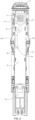
- the intelligent sensing dental irrigator comprises a body housing (not shown) and a body integration rack 1 disposed in an inner cavity of the body housing.
- the body housing is mainly used for accommodating the body integration rack 1 and other components.
- the body integration rack 1 is used for installing multiple components, such as sensing cover assembly 2 and machine-core assembly 4.
- the sensing cover assembly 2 is disposed at a top of the body housing, and may serve as part of a top structure of the body housing.
- the sensing cover assembly 2 (see FIG. 5 for details) is disposed above the body integration rack 1.
- the intelligent sensing dental irrigator features a layout where the sensor assembly 3 and the machine-core assembly 4 are separated.
- the sensing cover assembly 2 is disposed above the body integration rack 1, and the sensor assembly 3 is disposed on the sensing cover assembly 2, allowing the sensor assembly 3 to collect, by the sensing cover assembly 2, the facial information from the user.
- the machine-core assembly 4 is disposed on the body integration rack 1, and the two ends of the sensing data line 51 (which may be a wiring harness, for example, a flat cable) are electrically connected to the sensor assembly 3 and the machine-core assembly 4, respectively, allowing the facial information collected by the sensor assembly 3 to be transmitted to the machine-core assembly 4 by the sensing data line 51.
- the sensing data line 51 which may be a wiring harness, for example, a flat cable
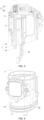
- the intelligent sensing dental irrigator further comprises a display screen 6 disposed on a side wall of the body integration rack 1.
- the data transmission assembly 5 further comprises a display data line 52 (which may also be a wiring harness, for example, a flat cable), and two ends of the display data line 52 are electrically connected to the display screen 6 and the machine-core assembly 4, respectively.
- the display screen 6 can be farther away from the water tank of the intelligent sensing dental irrigator, avoiding any impact on the water tank's capacity and reducing the assembly complexity for display screen 6.
- the display screen 6 can be fixed to the side wall of the body integration rack 1 through buckles.
- the data transmission assembly 5 further comprises display screen connectors 53.
- the display screen connectors 53 are disposed at an end portion of the display data line 52 and/or a machine-core circuit board 41 of the machine-core assembly 4, respectively, such that the display data line 52 and the machine-core circuit board 41 are configured to be plugged into each other.
- the display screen connectors 53 may consist of complementary male and female plugs. One of these plugs is disposed at the end portion of the display data line 52, while the other is disposed at the machine-core circuit board 41 of the machine-core assembly 4.
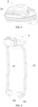
- the sensing cover assembly 2 comprises a cover 21, the cover 21 is provided with a groove 22 with a downward opening, and the sensor assembly 3 is disposed within the groove 22. Further, the sensor assembly 3 may be fixedly amounted onto the cover 21 through slot positioning posts and/or screws.
- the body integration rack 1 is made of transparent materials.
- the machine-core assembly 4 comprises a machine-core rack 42 and a machine-core circuit board 41, the machine-core circuit board 41 is disposed on the machine-core rack 42 and is electrically connected to the sensing data line 51, and the machine-core rack 42 has an auxiliary wiring slot 421 for constraining the sensing data line 51.
- the intelligent sensing dental irrigator of the present disclosure enhances communication reliability between the sensor assembly and the machine-core assembly by providing a more robust and streamlined laying path for the sensing data line. Therefore, the present disclosure effectively overcomes various shortcomings of the prior art and has a high industrial value.
Landscapes
- Health & Medical Sciences (AREA)
- Dentistry (AREA)
- Epidemiology (AREA)
- Life Sciences & Earth Sciences (AREA)
- Animal Behavior & Ethology (AREA)
- General Health & Medical Sciences (AREA)
- Public Health (AREA)
- Veterinary Medicine (AREA)
- Arrangements For Transmission Of Measured Signals (AREA)
- Dental Tools And Instruments Or Auxiliary Dental Instruments (AREA)
Applications Claiming Priority (2)
| Application Number | Priority Date | Filing Date | Title |
|---|---|---|---|
| CN202320861272.5U CN219538542U (zh) | 2023-04-17 | 2023-04-17 | 智能感应型冲牙器 |
| PCT/CN2023/130487 WO2024216934A1 (zh) | 2023-04-17 | 2023-11-08 | 智能感应型冲牙器 |
Publications (2)
| Publication Number | Publication Date |
|---|---|
| EP4501282A1 true EP4501282A1 (de) | 2025-02-05 |
| EP4501282A4 EP4501282A4 (de) | 2025-09-10 |
Family
ID=87705348
Family Applications (1)
| Application Number | Title | Priority Date | Filing Date |
|---|---|---|---|
| EP23933801.5A Pending EP4501282A4 (de) | 2023-04-17 | 2023-11-08 | Intelligenter sensorartiger mundspüler |
Country Status (3)
| Country | Link |
|---|---|
| EP (1) | EP4501282A4 (de) |
| CN (1) | CN219538542U (de) |
| WO (1) | WO2024216934A1 (de) |
Families Citing this family (1)
| Publication number | Priority date | Publication date | Assignee | Title |
|---|---|---|---|---|
| CN219538542U (zh) * | 2023-04-17 | 2023-08-18 | 上海飞象健康科技有限公司 | 智能感应型冲牙器 |
Family Cites Families (10)
| Publication number | Priority date | Publication date | Assignee | Title |
|---|---|---|---|---|
| KR20120113035A (ko) * | 2011-04-04 | 2012-10-12 | 주식회사 엘지생활건강 | 진동효율이 우수한 전동칫솔 |
| US20140250612A1 (en) * | 2013-03-05 | 2014-09-11 | Beam Technologies, Llc | Data Transferring Powered Toothbrush |
| CN213406374U (zh) * | 2020-07-07 | 2021-06-11 | 上海飞象健康科技有限公司 | 抽拉式冲牙器 |
| CN214679065U (zh) * | 2021-02-03 | 2021-11-12 | 上海飞象健康科技有限公司 | 具有唤醒功能的冲牙器 |
| CN214549692U (zh) * | 2021-03-02 | 2021-11-02 | 东莞市艾乐智能科技有限公司 | 一种冲牙器 |
| CN216876670U (zh) * | 2022-01-18 | 2022-07-05 | 上海飞象健康科技有限公司 | 喷嘴激活式冲牙器 |
| CN217472140U (zh) * | 2022-05-27 | 2022-09-23 | 广东小天才科技有限公司 | 可视化智能电动牙刷 |
| CN218356438U (zh) * | 2022-09-08 | 2023-01-24 | 广东美西科技有限公司 | 电动牙刷 |
| CN219538542U (zh) * | 2023-04-17 | 2023-08-18 | 上海飞象健康科技有限公司 | 智能感应型冲牙器 |
| CN219538543U (zh) * | 2023-04-17 | 2023-08-18 | 上海飞象健康科技有限公司 | 冲牙器的传感器组件安装结构 |
-
2023
- 2023-04-17 CN CN202320861272.5U patent/CN219538542U/zh active Active
- 2023-11-08 WO PCT/CN2023/130487 patent/WO2024216934A1/zh active Pending
- 2023-11-08 EP EP23933801.5A patent/EP4501282A4/de active Pending
Also Published As
| Publication number | Publication date |
|---|---|
| WO2024216934A1 (zh) | 2024-10-24 |
| CN219538542U (zh) | 2023-08-18 |
| EP4501282A4 (de) | 2025-09-10 |
Similar Documents
| Publication | Publication Date | Title |
|---|---|---|
| US6462953B2 (en) | Universal serial bus module and system | |
| US6141221A (en) | Universal serial bus docking station | |
| EP4501282A1 (de) | Intelligenter sensorartiger mundspüler | |
| TWM422178U (en) | Photoelectric signal converting module | |
| US20040242066A1 (en) | Differential transmission connector | |
| CN219538543U (zh) | 冲牙器的传感器组件安装结构 | |
| CN206270801U (zh) | 一种头戴显示设备 | |
| US7806732B1 (en) | Connector assembly | |
| CN212725753U (zh) | 具有防尘功能的易插拔串口服务器 | |
| CN210809428U (zh) | 一种方便的腰带 | |
| CN201126545Y (zh) | 一种电脑集线盒 | |
| CN220655545U (zh) | 一种包括内窥镜的口腔医疗器械 | |
| CN207052914U (zh) | 一种应用于立体成像测量系统的采集切换装置及系统 | |
| CN218334577U (zh) | 一种基于86盒的音视频信号网络传输器 | |
| CN219393953U (zh) | 一种多功能传输连接线 | |
| CN207398551U (zh) | 转接线 | |
| CN207490894U (zh) | 红外线人体感应开关 | |
| CN222072360U (zh) | 一种防误拔的自带pcb板的免工具水晶插头 | |
| CN219477186U (zh) | 一种新型USBType-C母座连接器 | |
| CN218112853U (zh) | 配件连接线集成结构及电动单车 | |
| CN105226422B (zh) | 一种可双面插接的USB2.0Micro‑B型USB插头 | |
| CN112290257B (zh) | 一种lvds线端连接器 | |
| CN218732261U (zh) | 一种可替换的多充电口立体插座 | |
| CN216599623U (zh) | 一种便携式光通信光纤巡检仪 | |
| CN211629378U (zh) | 一种内部连接导线用多功能连接器 |
Legal Events
| Date | Code | Title | Description |
|---|---|---|---|
| STAA | Information on the status of an ep patent application or granted ep patent |
Free format text: STATUS: THE INTERNATIONAL PUBLICATION HAS BEEN MADE |
|
| PUAI | Public reference made under article 153(3) epc to a published international application that has entered the european phase |
Free format text: ORIGINAL CODE: 0009012 |
|
| STAA | Information on the status of an ep patent application or granted ep patent |
Free format text: STATUS: REQUEST FOR EXAMINATION WAS MADE |
|
| 17P | Request for examination filed |
Effective date: 20241028 |
|
| AK | Designated contracting states |
Kind code of ref document: A1 Designated state(s): AL AT BE BG CH CY CZ DE DK EE ES FI FR GB GR HR HU IE IS IT LI LT LU LV MC ME MK MT NL NO PL PT RO RS SE SI SK SM TR |
|
| A4 | Supplementary search report drawn up and despatched |
Effective date: 20250808 |
|
| RIC1 | Information provided on ipc code assigned before grant |
Ipc: A61C 17/02 20060101AFI20250804BHEP |