EP4501232A1 - Verfahren und vorrichtung zur überwachung von anomalien bioelektrischer signale - Google Patents
Verfahren und vorrichtung zur überwachung von anomalien bioelektrischer signale Download PDFInfo
- Publication number
- EP4501232A1 EP4501232A1 EP23910270.0A EP23910270A EP4501232A1 EP 4501232 A1 EP4501232 A1 EP 4501232A1 EP 23910270 A EP23910270 A EP 23910270A EP 4501232 A1 EP4501232 A1 EP 4501232A1
- Authority
- EP
- European Patent Office
- Prior art keywords
- electrode
- collection
- noise signal
- digital
- signal
- Prior art date
- Legal status (The legal status is an assumption and is not a legal conclusion. Google has not performed a legal analysis and makes no representation as to the accuracy of the status listed.)
- Pending
Links
Images

Classifications
-
- A—HUMAN NECESSITIES
- A61—MEDICAL OR VETERINARY SCIENCE; HYGIENE
- A61B—DIAGNOSIS; SURGERY; IDENTIFICATION
- A61B5/00—Measuring for diagnostic purposes; Identification of persons
- A61B5/24—Detecting, measuring or recording bioelectric or biomagnetic signals of the body or parts thereof
- A61B5/25—Bioelectric electrodes therefor
- A61B5/276—Protection against electrode failure
-
- A—HUMAN NECESSITIES
- A61—MEDICAL OR VETERINARY SCIENCE; HYGIENE
- A61B—DIAGNOSIS; SURGERY; IDENTIFICATION
- A61B5/00—Measuring for diagnostic purposes; Identification of persons
- A61B5/24—Detecting, measuring or recording bioelectric or biomagnetic signals of the body or parts thereof
- A61B5/316—Modalities, i.e. specific diagnostic methods
-
- A—HUMAN NECESSITIES
- A61—MEDICAL OR VETERINARY SCIENCE; HYGIENE
- A61B—DIAGNOSIS; SURGERY; IDENTIFICATION
- A61B5/00—Measuring for diagnostic purposes; Identification of persons
- A61B5/05—Detecting, measuring or recording for diagnosis by means of electric currents or magnetic fields; Measuring using microwaves or radio waves
- A61B5/053—Measuring electrical impedance or conductance of a portion of the body
-
- A—HUMAN NECESSITIES
- A61—MEDICAL OR VETERINARY SCIENCE; HYGIENE
- A61B—DIAGNOSIS; SURGERY; IDENTIFICATION
- A61B5/00—Measuring for diagnostic purposes; Identification of persons
- A61B5/24—Detecting, measuring or recording bioelectric or biomagnetic signals of the body or parts thereof
- A61B5/25—Bioelectric electrodes therefor
-
- A—HUMAN NECESSITIES
- A61—MEDICAL OR VETERINARY SCIENCE; HYGIENE
- A61B—DIAGNOSIS; SURGERY; IDENTIFICATION
- A61B5/00—Measuring for diagnostic purposes; Identification of persons
- A61B5/24—Detecting, measuring or recording bioelectric or biomagnetic signals of the body or parts thereof
- A61B5/30—Input circuits therefor
- A61B5/305—Common mode rejection
-
- A—HUMAN NECESSITIES
- A61—MEDICAL OR VETERINARY SCIENCE; HYGIENE
- A61B—DIAGNOSIS; SURGERY; IDENTIFICATION
- A61B5/00—Measuring for diagnostic purposes; Identification of persons
- A61B5/24—Detecting, measuring or recording bioelectric or biomagnetic signals of the body or parts thereof
- A61B5/316—Modalities, i.e. specific diagnostic methods
- A61B5/318—Heart-related electrical modalities, e.g. electrocardiography [ECG]
-
- A—HUMAN NECESSITIES
- A61—MEDICAL OR VETERINARY SCIENCE; HYGIENE
- A61B—DIAGNOSIS; SURGERY; IDENTIFICATION
- A61B5/00—Measuring for diagnostic purposes; Identification of persons
- A61B5/24—Detecting, measuring or recording bioelectric or biomagnetic signals of the body or parts thereof
- A61B5/316—Modalities, i.e. specific diagnostic methods
- A61B5/369—Electroencephalography [EEG]
-
- A—HUMAN NECESSITIES
- A61—MEDICAL OR VETERINARY SCIENCE; HYGIENE
- A61B—DIAGNOSIS; SURGERY; IDENTIFICATION
- A61B5/00—Measuring for diagnostic purposes; Identification of persons
- A61B5/24—Detecting, measuring or recording bioelectric or biomagnetic signals of the body or parts thereof
- A61B5/316—Modalities, i.e. specific diagnostic methods
- A61B5/389—Electromyography [EMG]
-
- A—HUMAN NECESSITIES
- A61—MEDICAL OR VETERINARY SCIENCE; HYGIENE
- A61B—DIAGNOSIS; SURGERY; IDENTIFICATION
- A61B5/00—Measuring for diagnostic purposes; Identification of persons
- A61B5/72—Signal processing specially adapted for physiological signals or for diagnostic purposes
- A61B5/7203—Signal processing specially adapted for physiological signals or for diagnostic purposes for noise prevention, reduction or removal
-
- A—HUMAN NECESSITIES
- A61—MEDICAL OR VETERINARY SCIENCE; HYGIENE
- A61B—DIAGNOSIS; SURGERY; IDENTIFICATION
- A61B5/00—Measuring for diagnostic purposes; Identification of persons
- A61B5/72—Signal processing specially adapted for physiological signals or for diagnostic purposes
- A61B5/7221—Determining signal validity, reliability or quality
-
- A—HUMAN NECESSITIES
- A61—MEDICAL OR VETERINARY SCIENCE; HYGIENE
- A61B—DIAGNOSIS; SURGERY; IDENTIFICATION
- A61B5/00—Measuring for diagnostic purposes; Identification of persons
- A61B5/72—Signal processing specially adapted for physiological signals or for diagnostic purposes
- A61B5/7225—Details of analogue processing, e.g. isolation amplifier, gain or sensitivity adjustment, filtering, baseline or drift compensation
-
- A—HUMAN NECESSITIES
- A61—MEDICAL OR VETERINARY SCIENCE; HYGIENE
- A61B—DIAGNOSIS; SURGERY; IDENTIFICATION
- A61B5/00—Measuring for diagnostic purposes; Identification of persons
- A61B5/72—Signal processing specially adapted for physiological signals or for diagnostic purposes
- A61B5/7235—Details of waveform analysis
- A61B5/725—Details of waveform analysis using specific filters therefor, e.g. Kalman or adaptive filters
-
- A—HUMAN NECESSITIES
- A61—MEDICAL OR VETERINARY SCIENCE; HYGIENE
- A61B—DIAGNOSIS; SURGERY; IDENTIFICATION
- A61B5/00—Measuring for diagnostic purposes; Identification of persons
- A61B5/74—Details of notification to user or communication with user or patient; User input means
- A61B5/746—Alarms related to a physiological condition, e.g. details of setting alarm thresholds or avoiding false alarms
-
- A—HUMAN NECESSITIES
- A61—MEDICAL OR VETERINARY SCIENCE; HYGIENE
- A61B—DIAGNOSIS; SURGERY; IDENTIFICATION
- A61B2560/00—Constructional details of operational features of apparatus; Accessories for medical measuring apparatus
- A61B2560/02—Operational features
- A61B2560/0266—Operational features for monitoring or limiting apparatus function
- A61B2560/0276—Determining malfunction
Definitions
- the present application relates to a technical field of sensor circuit design, and, in particular, to a method and device for monitoring abnormal bioelectric signals.
- Electro X gram includes electroencephalography (EEG), electrocardiogram (ECG), and electromyogram (EMG), collecting bioelectrograms is a detection method for studying potential and polarity changes that occur in organs, tissues, and cells during biological activities.
- Circuit systems of bioelectrogram acquisition devices are fundamentally the same, but an accuracy of each signal is slightly different, often, there are a plurality of electrodes used for collecting bioelectrograms in the circuit, if one of the electrodes used for collecting bioelectrograms in the circuit falls off or is poorly connected, the device cannot accurately detect a potential state; even worse, when the electrode is unloaded, various electromagnetic radiation from the air can accumulate on the electrode, causing the device to detect abnormal potential waveforms. Therefore, an electrode detachment detection technology of multi-electrode bioelectrogram acquisition device, furthermore, based on electrode detachment detection technology, abnormal monitoring of bioelectric signals can be achieved, which is a very important technology.
- an additional bioelectric signal abnormal monitoring circuit is connected to each electrode on a basis of being connected to an acquisition circuit, then, through an optocoupler-isolation circuit, IO quantity is output to a microcontroller chip MCU to achieve active abnormal monitoring of bioelectric signals, thereby realizing abnormal monitoring of bioelectric signals.
- each electrode lead wire needs to be connected to a bioelectric signal abnormal monitoring circuit (if there are 100 lead wires, an additional 100 monitoring circuits need to be added to a circuit board), which will increase a size of the circuit board, similarly, shell volume of the bioelectrogram acquisition device will also increase, making a product bulky.
- an embodiment of the present application provides a method and device for monitoring abnormalities in biological electrical signals, aiming to eliminate or improve one or more defects present in the existing technology.
- a multi-electrode bioelectrogram acquisition device comprises a reference electrode, a right leg drive electrode, and a plurality of collection electrodes.
- one of the collection electrodes serves as a positive electrode of the multi-electrode bioelectrogram acquisition device
- the reference electrode serves as a negative electrode of the multi-electrode bioelectrogram acquisition device
- the noise signal is generated using self-excited oscillation of a Wen bridge or produced through a Direct Digital Frequency Synthesis DDS.
- the front-end circuit comprises a differential amplifier circuit, a follower circuit, and a wave filter, the analog signals from the reference electrode and each collection electrode are preprocessed through the differential amplifier circuit, the follower circuit, and the wave filter.
- types of the computation and analysis unit comprise a microcontroller unit MCU, a central processing unit CPU, and a personal computer PC.
- the computation and analysis unit determines the connection state of the collection electrode according to the calculated human impedance and the preset impedance measurement standards, comprising: if a magnitude of the human impedance does not exceed a first standard of the preset impedance measurement standards, determining that the electrode is in a stable connection state; if the magnitude of the human impedance exceeds the first standard but does not exceed a second standard of the preset impedance measurement standards, determining that the electrode is in an unstable connection state; if the magnitude of the human impedance exceeds the second standard, determining that the electrode is in a detached state.
- the method further comprises: generating alert information for the collection electrode in a detected unstable connection state.
- a multi-electrode bioelectrogram acquisition device comprises a reference electrode, a right leg drive electrode, and a plurality of collection electrodes, one of the collection electrodes serves as a positive electrode of the multi-electrode bioelectrogram acquisition device, and the reference electrode serves as a negative electrode of the multi-electrode bioelectrogram acquisition device, the device comprises:
- the method and device for monitoring abnormal bioelectric signals of the present application on an aspect, based on the device of the method, especially a volume of a circuit board will not increase, which can effectively avoid a bulky shell volume of the bioelectrogram acquisition device, on the other aspect, based on the method of passive detachment monitoring, which can effectively avoid interference to an acquisition circuit.
- connection in the article can not only refer to a direct connection, but also to an indirect connection with an intermediate object.
- the present application provides a method and device for monitoring abnormal bioelectric signals.
- Electro X gram includes electroencephalography (EEG), electrocardiography (ECG), and electromyogram (EMG). Collecting bioelectrograms is a detection method for studying potential and polarity changes that occur in organs, tissues, and cells during biological activities.
- a circuit system of the bioelectrogram acquisition device is a same, but a measurement accuracy of each signal is slightly different, often, a plurality of electrodes need to be connected to organisms
- the bioelectrogram acquisition device includes a reference electrode (REF/ref), a right leg drive electrode (RLD), and a plurality of collection electrodes (also directly referred to as electrodes)
- the collection electrode serves as a positive electrode of the multi-electrode bioelectrogram acquisition device
- the reference electrode serves as a negative electrode of the multi-electrodelectrogram acquisition device, configured as a reference for measuring the potential of the collection electrode
- a right leg drive circuit corresponding to the right leg drive electrode is usually configured for biological signal amplification to reduce common-mode interference and eliminate interference noise (mainly for household power supply noise at 50-60Hz).
- a detection process of bioelectrogram if electrode detachment is not detected in a timely manner, it may lead to data contamination.
- the method for monitoring abnormal bioelectric signals proposed by the present application is based on circuit design and detection of an electrode connection state of the multi-electrode bioelectrogram acquisition device to achieve.
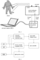
- FIG. 2 is a schematic diagram of the ECG detection system, collection electrode L1 and collection electrode L2 (In a case of electroencephalogram(EEG) acquisition device, there would be more electrodes) are connected to both hands of a subject, and the right leg drive electrode RLD is connected to the right leg of the subject to weaken common-mode interference and improve common-mode rejection ratio, a connection position of the reference electrode is generally in a weak signal area, such as an ear for EEG, and in a muscle-free area like a wrist for electromyography (EMG).
- ECG electrocardiogram
- All electrodes are connected to the ECG detection circuit, which is connected to a multifunctional recorder (Digital Radiography Data Acquisition Equipment, DR DAQ), to jointly detect potential changes between collection electrode L1 and the collection electrode L2, and the multifunctional recorder is connected to a personal computer to display the ECG collected by the ECG acquisition device.
- a multifunctional recorder Digital Radiography Data Acquisition Equipment, DR DAQ
- FIG. 3 illustrates a schematic circuit diagram of an abnormal monitoring circuit for bioelectric signals in the prior art, each electrode is additionally connected to a separate abnormal monitoring circuit for bioelectric signals, which is then connected to an optocoupler-isolation circuit, and the optocoupler-isolation circuit is connected to a microcontroller to achieve abnormal bioelectric signals monitoring. It is manageable when there are only a few electrodes to collect, but if a number of electrodes increases, such as in EEG acquisition device, it will greatly increase a burden of circuit design, resulting in bulky circuit boards and even an entire device.
- Step S130 a front-end circuit preprocesses analog signals from the reference electrode and each collection electrode, and outputs the preprocessed analog signals corresponding to each collection electrode to an analog-to-digital converter (ADC), and the preprocessing includes differential amplification.
- ADC analog-to-digital converter
- the ADC chip is configured to convert analog signals into digital signals.
- the front-end circuit in step S130 includes a differential amplifier circuit, a follower circuit, and a wave filter. The analog signals from the reference electrode and each collection electrode are preprocessed through the differential amplifier circuit, the follower circuit, and the wave filter.
- Step S140 the ADC converts the preprocessed analog signals corresponding to each collection electrode into digital signals, and transmits the digital signals corresponding to each collection electrode to an computation and analysis unit.
- Step S160 the computation and analysis unit determines a connection state of the collection electrode based on a calculated human impedance and preset impedance measurement standards, and abnormal monitoring of bioelectric signals is achieved based on periodic judgment of the connection state of the collection electrode.
- types of the computation and analysis unit in step S150 and S160 include a microcontroller unit (MCU), a central processing unit (CPU), and a personal computer (PC).
- MCU microcontroller unit
- CPU central processing unit
- PC personal computer
- the computation and analysis unit determines the connection state of the collection electrode according to the calculated human impedance and the preset impedance measurement standards, which includes: 1) if a magnitude of the human impedance does not exceed a first standard of the preset impedance measurement standard, the electrode is judged to be in a stable connection state; 2) if the magnitude of the human impedance exceeds the first standard but does not exceed a second standard of the preset impedance measurement standards, the electrode is judged to be in an unstable connection state; 3) if the magnitude of the human impedance exceeds the second standard, the electrode is judged to be in a detached state.
- the electrode when the human impedance is within 1000 ⁇ , the electrode is judged to be in a stable connection state, when the human impedance is greater than 1000 ⁇ but not exceeding 7000 ⁇ , the electrode is judged to be in an unstable connection state, when the human impedance is greater than 7000 ⁇ , the electrode is judged to be in the detached state.
- connection state of the collection electrode is the unstable connection state or the detached state
- alerting for abnormal bioelectric signals can be provided on a human-computer interaction interface GUI.
- the method further includes: generating alert information for the collection electrode in a detected unstable connection state. For example, an alert message pops up on a bioelectrogram display interface, or a serial number of the collection electrode with detachment/unstable connection state is displayed on the bioelectrogram display interface. Alternatively, based on the detected unstable connection state of the collection electrode, the abnormal bioelectric signals is determined and an alert information is generated.
- the noise signal is overlaid on the reference electrode, when a sine wave noise signal is added to the reference electrode, if the impedance increases, this situation can still be recognized, however, if the electrode falls off, it cannot be well recognized because the sine wave signal cannot form a loop at this time, resulting in a measured noise value of almost 0, however, in reality, with good connection and impedance, the noise value is also close to 0.
- this limitation exists, it also has certain application prospects in certain specific scenarios.
- FIG. 4 shows a circuit schematic diagram of a multi-electrode bioelectrogram acquisition device according to an embodiment of the present application.
- Lead wires 1 to n are respectively connected to collection electrodes 1 to n, and the reference electrodes REF and are connected to REF, the signals 1 to n from reference electrodes 1 to n pass through the differential amplifier circuit, the follower circuit, and the wave filter to reach the ADC chip, the ADC chip converts the analog signal into the digital signal and sends it to the microprocessor MCU, the right leg drive electrode is connected to a RLD line, and the noise signal from the signal generator is overlaid on the right leg drive electrode and collected by the collection electrodes 1 to n through an emission in a human body.
- connection state of the right leg drive electrode is good.
- the monitoring method provided by the present application will detecte an anomaly in human impedance at the microprocessor chip MCU, thereby, thereby, determining abnormal bioelectric signals.
- the standard for determining abnormal human impedance is set based on an actual application scenarios of this technology.
- AGND indicates a virtual ground, indicating a connection to an analog ground wire, which is mainly used in analog circuits.
- a principle of the present application is based on a virtual short and virtual break principle of the operational amplifiers.
- the right leg drive is used to weaken common-mode noise, that is, the noise on the negative and positive electrodes of the differential amplifier circuit, the noise on both the negative and positive electrodes is reduced, and the noise obtained by the difference between the negative and positive electrodes will also be weakened.
- common-mode noise that is, the noise on the negative and positive electrodes of the differential amplifier circuit
- the noise on both the negative and positive electrodes is reduced, and the noise obtained by the difference between the negative and positive electrodes will also be weakened.
- differential amplification calculates an original signal from the collection electrodes, and this difference is a result of the filtered values before and after, which is calculated once per second.
- the present application further provides a device for monitoring abnormal bioelectric signals
- the multi-electrode bioelectrogram acquisition device includes a reference electrode, a right leg drive electrode, and a plurality of collection electrodes, the collection electrode serves as a positive electrode of the multi-electrode bioelectrogram acquisition device, and the reference electrode serves as a negative electrode of the multi-electrode bioelectrogram acquisition device, this device includes:
- types of the computation and analysis unit include a microcontroller unit MCU, a central processing unit CPU, and a personal computer PC.
- the method and device for monitoring abnormal bioelectric signals provided by the present application, on one hand, it is unnecessary to add a large number of bioelectric signal abnormal monitoring circuits in a multi-electrode scenario, thus, avoiding an increase in a size of a circuit board and can effectively avoid a bulky shell volume of the bioelectric signal acquisition device, on the other hand, based on a passive bioelectric signal abnormal monitoring method, it can effectively avoid interference with an acquisition circuit.
- active monitoring is a monitoring method triggered by the abnormal monitoring circuit of bioelectric signals, which can interfere with the acquisition circuit and affect an accuracy of bioelectrogram acquisition, however, the method of the present application has no action initiated by the circuit, only an additional step of band-stop filtering is added in an operational unit, a passive monitoring method provided by the present application can effectively avoid interference to the acquisition circuit, and a principle of noise signal target acquisition frequency band is generated and will be processed by band-stop filtering, so it will not affect an accuracy of bioelectrogram acquisition.
- EEG acquisition is a typical scenario with multiple electrodes, if existing technology is used, there should be a corresponding monitoring circuit for each electrode, if it is 100 lead wires, one hundred monitoring circuits need to be added to the circuit board, which will increase the board volume and the shell volume, making a product bulky and very unfavorable for testing and sales.
- the exemplary components, systems, and methods described in conjunction with the disclosed embodiments can be executed in the hardware, software, or a combination of both. Whether to execute it in the hardware or software depends on a specific application and design constraints of the technical solution. Professional and technical personnel can use different methods to achieve the described functions for each specific application, but such implementation should not be considered beyond the scope of the present application.
- the hardware it can be, for example, electronic circuits, application specific integrated circuits (ASICs), appropriate firmware, plugins, function cards, etc.
- ASICs application specific integrated circuits
- the elements of the present application are programs or code segments configured to execute the required tasks.
- the programs or the code segments can be stored in the machine readable media, or transmitted on transmission medium or communication links through the data signals carried by carriers.
Landscapes
- Health & Medical Sciences (AREA)
- Life Sciences & Earth Sciences (AREA)
- Engineering & Computer Science (AREA)
- Surgery (AREA)
- General Health & Medical Sciences (AREA)
- Biophysics (AREA)
- Pathology (AREA)
- Veterinary Medicine (AREA)
- Biomedical Technology (AREA)
- Heart & Thoracic Surgery (AREA)
- Medical Informatics (AREA)
- Molecular Biology (AREA)
- Public Health (AREA)
- Animal Behavior & Ethology (AREA)
- Physics & Mathematics (AREA)
- Signal Processing (AREA)
- Physiology (AREA)
- Psychiatry (AREA)
- Artificial Intelligence (AREA)
- Computer Vision & Pattern Recognition (AREA)
- Power Engineering (AREA)
- Nuclear Medicine, Radiotherapy & Molecular Imaging (AREA)
- Radiology & Medical Imaging (AREA)
- Psychology (AREA)
- Cardiology (AREA)
- Measurement And Recording Of Electrical Phenomena And Electrical Characteristics Of The Living Body (AREA)
Applications Claiming Priority (2)
| Application Number | Priority Date | Filing Date | Title |
|---|---|---|---|
| CN202211735686.XA CN116584950B (zh) | 2022-12-31 | 2022-12-31 | 一种生物电信号异常监测方法和装置 |
| PCT/CN2023/139896 WO2024140340A1 (zh) | 2022-12-31 | 2023-12-19 | 一种生物电信号异常监测方法和装置 |
Publications (2)
| Publication Number | Publication Date |
|---|---|
| EP4501232A1 true EP4501232A1 (de) | 2025-02-05 |
| EP4501232A4 EP4501232A4 (de) | 2025-07-09 |
Family
ID=87597824
Family Applications (1)
| Application Number | Title | Priority Date | Filing Date |
|---|---|---|---|
| EP23910270.0A Pending EP4501232A4 (de) | 2022-12-31 | 2023-12-19 | Verfahren und vorrichtung zur überwachung von anomalien bioelektrischer signale |
Country Status (4)
| Country | Link |
|---|---|
| US (1) | US20250049367A1 (de) |
| EP (1) | EP4501232A4 (de) |
| CN (1) | CN116584950B (de) |
| WO (1) | WO2024140340A1 (de) |
Families Citing this family (1)
| Publication number | Priority date | Publication date | Assignee | Title |
|---|---|---|---|---|
| CN116584950B (zh) * | 2022-12-31 | 2024-05-24 | 北京津发科技股份有限公司 | 一种生物电信号异常监测方法和装置 |
Family Cites Families (10)
| Publication number | Priority date | Publication date | Assignee | Title |
|---|---|---|---|---|
| AU4907385A (en) * | 1984-11-06 | 1986-05-15 | Spacelabs, Inc. | Lead fail detection in electrocardiography |
| JPH11332839A (ja) * | 1998-05-26 | 1999-12-07 | Nec Gumma Ltd | 電極異常検出回路 |
| US6597942B1 (en) * | 2000-08-15 | 2003-07-22 | Cardiac Pacemakers, Inc. | Electrocardiograph leads-off indicator |
| KR101036057B1 (ko) * | 2009-03-24 | 2011-05-19 | 주식회사 바이오스페이스 | 생체 임피던스 측정 장치 및 그 측정 방법 |
| KR101036053B1 (ko) * | 2009-03-30 | 2011-05-19 | 주식회사 바이오스페이스 | 생체 임피던스 측정 장치 및 그 측정 방법 |
| CN102613969B (zh) * | 2012-04-28 | 2016-01-06 | 深圳市理邦精密仪器股份有限公司 | 一种导联脱落判断方法与装置 |
| WO2014051590A1 (en) * | 2012-09-27 | 2014-04-03 | Draeger Medical Systems, Inc. | System and method for detecting a status of electrodes of a patient monitoring device |
| KR101692783B1 (ko) * | 2015-06-09 | 2017-01-04 | (주) 로임시스템 | 임피던스 측정장치 |
| CN205215225U (zh) * | 2015-11-27 | 2016-05-11 | 大连大学 | 人体阻抗测量电路 |
| CN116584950B (zh) * | 2022-12-31 | 2024-05-24 | 北京津发科技股份有限公司 | 一种生物电信号异常监测方法和装置 |
-
2022
- 2022-12-31 CN CN202211735686.XA patent/CN116584950B/zh active Active
-
2023
- 2023-12-19 WO PCT/CN2023/139896 patent/WO2024140340A1/zh not_active Ceased
- 2023-12-19 EP EP23910270.0A patent/EP4501232A4/de active Pending
-
2024
- 2024-10-31 US US18/932,701 patent/US20250049367A1/en active Pending
Also Published As
| Publication number | Publication date |
|---|---|
| CN116584950B (zh) | 2024-05-24 |
| WO2024140340A1 (zh) | 2024-07-04 |
| EP4501232A4 (de) | 2025-07-09 |
| US20250049367A1 (en) | 2025-02-13 |
| CN116584950A (zh) | 2023-08-15 |
Similar Documents
| Publication | Publication Date | Title |
|---|---|---|
| US11337633B1 (en) | Method and system for electrode impedance measurement | |
| EP2688468B1 (de) | Vorrichtung und verfahren zur messung der qualität physiologischer signale | |
| US20250049367A1 (en) | Bioelectrical signal abnormality monitoring method and apparatus | |
| CN202179534U (zh) | 超小型房颤检测装置 | |
| CN113100776B (zh) | 一种融合肌电和心电信号的疲劳监测系统及方法 | |
| Lu et al. | A portable ECG monitor with low power consumption and small size based on AD8232 chip | |
| KR20160107390A (ko) | 심전도 신호 측정장치 | |
| CN104905773A (zh) | 臂带式生命指征采集系统、处理系统及方法、监测系统 | |
| CN118614950A (zh) | 一种基于掌上超声设备的健康状态评估系统及方法 | |
| Bauzha et al. | Electrocardiogram measurement complex based on microcontrollers and wireless networks | |
| CN103222864B (zh) | 一种自适应心电检测方法及其监控系统 | |
| CN115153580B (zh) | 一种用于胎儿心电监测的皮肤阻抗测量方法和系统 | |
| CN105997095A (zh) | 一种基于电极阵列的胎动实时监测的方法及装置 | |
| Choo et al. | Android based self-diagnostic electrocardiogram system for mobile healthcare | |
| Padma et al. | ECG compression and labview implementation | |
| Wu et al. | An ECG extraction and reconstruction system with dynamic EMG filtering implemented on an ARM chip | |
| CN106798546A (zh) | 数据采集处理终端 | |
| CN105249956A (zh) | 一种基于放大电路的心电监护系统 | |
| CN213606426U (zh) | 一种动态抗干扰便携式心电自动分析仪 | |
| CN201814572U (zh) | 一种便携式心电数据实时采集装置 | |
| CN204683576U (zh) | 一种心电监控监护装置 | |
| CN202027575U (zh) | 一种呼吸肌电采集与检测装置 | |
| Feng et al. | The design of low power portable ECG monitor | |
| US20230397873A1 (en) | RRI Measurement Device, RRI Measurement Method and RRI Measurement Program | |
| Luiz et al. | ECG and sEMG Conditioning and Wireless Transmission with a Biosignal Acquisition Board |
Legal Events
| Date | Code | Title | Description |
|---|---|---|---|
| STAA | Information on the status of an ep patent application or granted ep patent |
Free format text: STATUS: THE INTERNATIONAL PUBLICATION HAS BEEN MADE |
|
| PUAI | Public reference made under article 153(3) epc to a published international application that has entered the european phase |
Free format text: ORIGINAL CODE: 0009012 |
|
| STAA | Information on the status of an ep patent application or granted ep patent |
Free format text: STATUS: REQUEST FOR EXAMINATION WAS MADE |
|
| 17P | Request for examination filed |
Effective date: 20241030 |
|
| AK | Designated contracting states |
Kind code of ref document: A1 Designated state(s): AL AT BE BG CH CY CZ DE DK EE ES FI FR GB GR HR HU IE IS IT LI LT LU LV MC ME MK MT NL NO PL PT RO RS SE SI SK SM TR |
|
| STAA | Information on the status of an ep patent application or granted ep patent |
Free format text: STATUS: EXAMINATION IS IN PROGRESS |
|
| A4 | Supplementary search report drawn up and despatched |
Effective date: 20250605 |
|
| RIC1 | Information provided on ipc code assigned before grant |
Ipc: A61B 5/389 20210101ALI20250530BHEP Ipc: A61B 5/369 20210101ALI20250530BHEP Ipc: A61B 5/318 20210101ALI20250530BHEP Ipc: A61B 5/316 20210101ALI20250530BHEP Ipc: A61B 5/25 20210101ALI20250530BHEP Ipc: A61B 5/276 20210101AFI20250530BHEP |
|
| 17Q | First examination report despatched |
Effective date: 20250624 |