EP4498552A1 - Multilane power distribution system - Google Patents
Multilane power distribution system Download PDFInfo
- Publication number
- EP4498552A1 EP4498552A1 EP24182305.3A EP24182305A EP4498552A1 EP 4498552 A1 EP4498552 A1 EP 4498552A1 EP 24182305 A EP24182305 A EP 24182305A EP 4498552 A1 EP4498552 A1 EP 4498552A1
- Authority
- EP
- European Patent Office
- Prior art keywords
- power
- sspc
- pulse
- distribution system
- multilane
- Prior art date
- Legal status (The legal status is an assumption and is not a legal conclusion. Google has not performed a legal analysis and makes no representation as to the accuracy of the status listed.)
- Withdrawn
Links
Images


Classifications
-
- H—ELECTRICITY
- H02—GENERATION; CONVERSION OR DISTRIBUTION OF ELECTRIC POWER
- H02J—ELECTRIC POWER NETWORKS; CIRCUIT ARRANGEMENTS OR SYSTEMS FOR SUPPLYING OR DISTRIBUTING ELECTRIC POWER; SYSTEMS FOR STORING ELECTRIC ENERGY
- H02J1/00—Circuit arrangements for DC mains or DC distribution networks
- H02J1/08—Three-wire DC power distribution systems; Systems having more than three wires
- H02J1/084—Three-wire DC power distribution systems; Systems having more than three wires for selectively connecting the load or loads to one or several among a plurality of power lines or power sources
-
- H—ELECTRICITY
- H02—GENERATION; CONVERSION OR DISTRIBUTION OF ELECTRIC POWER
- H02M—APPARATUS FOR CONVERSION BETWEEN AC AND AC, BETWEEN AC AND DC, OR BETWEEN DC AND DC, AND FOR USE WITH MAINS OR SIMILAR POWER SUPPLY SYSTEMS; CONVERSION OF DC OR AC INPUT POWER INTO SURGE OUTPUT POWER; CONTROL OR REGULATION THEREOF
- H02M3/00—Conversion of DC power input into DC power output
- H02M3/02—Conversion of DC power input into DC power output without intermediate conversion into AC
- H02M3/04—Conversion of DC power input into DC power output without intermediate conversion into AC by static converters
- H02M3/10—Conversion of DC power input into DC power output without intermediate conversion into AC by static converters using discharge tubes with control electrode or semiconductor devices with control electrode
- H02M3/145—Conversion of DC power input into DC power output without intermediate conversion into AC by static converters using discharge tubes with control electrode or semiconductor devices with control electrode using devices of a triode or transistor type requiring continuous application of a control signal
- H02M3/155—Conversion of DC power input into DC power output without intermediate conversion into AC by static converters using discharge tubes with control electrode or semiconductor devices with control electrode using devices of a triode or transistor type requiring continuous application of a control signal using semiconductor devices only
- H02M3/156—Conversion of DC power input into DC power output without intermediate conversion into AC by static converters using discharge tubes with control electrode or semiconductor devices with control electrode using devices of a triode or transistor type requiring continuous application of a control signal using semiconductor devices only with automatic control of output voltage or current, e.g. switching regulators
- H02M3/158—Conversion of DC power input into DC power output without intermediate conversion into AC by static converters using discharge tubes with control electrode or semiconductor devices with control electrode using devices of a triode or transistor type requiring continuous application of a control signal using semiconductor devices only with automatic control of output voltage or current, e.g. switching regulators including plural semiconductor devices as final control devices for a single load
- H02M3/1584—Conversion of DC power input into DC power output without intermediate conversion into AC by static converters using discharge tubes with control electrode or semiconductor devices with control electrode using devices of a triode or transistor type requiring continuous application of a control signal using semiconductor devices only with automatic control of output voltage or current, e.g. switching regulators including plural semiconductor devices as final control devices for a single load with a plurality of power processing stages connected in parallel
-
- H—ELECTRICITY
- H02—GENERATION; CONVERSION OR DISTRIBUTION OF ELECTRIC POWER
- H02J—ELECTRIC POWER NETWORKS; CIRCUIT ARRANGEMENTS OR SYSTEMS FOR SUPPLYING OR DISTRIBUTING ELECTRIC POWER; SYSTEMS FOR STORING ELECTRIC ENERGY
- H02J1/00—Circuit arrangements for DC mains or DC distribution networks
- H02J1/08—Three-wire DC power distribution systems; Systems having more than three wires
- H02J1/084—Three-wire DC power distribution systems; Systems having more than three wires for selectively connecting the load or loads to one or several among a plurality of power lines or power sources
- H02J1/086—Three-wire DC power distribution systems; Systems having more than three wires for selectively connecting the load or loads to one or several among a plurality of power lines or power sources for providing alternative feeding paths between load or loads and source or sources when the main path fails
-
- H—ELECTRICITY
- H02—GENERATION; CONVERSION OR DISTRIBUTION OF ELECTRIC POWER
- H02J—ELECTRIC POWER NETWORKS; CIRCUIT ARRANGEMENTS OR SYSTEMS FOR SUPPLYING OR DISTRIBUTING ELECTRIC POWER; SYSTEMS FOR STORING ELECTRIC ENERGY
- H02J1/00—Circuit arrangements for DC mains or DC distribution networks
- H02J1/10—Parallel operation of DC sources
- H02J1/102—Parallel operation of DC sources being switching converters
-
- H—ELECTRICITY
- H02—GENERATION; CONVERSION OR DISTRIBUTION OF ELECTRIC POWER
- H02J—ELECTRIC POWER NETWORKS; CIRCUIT ARRANGEMENTS OR SYSTEMS FOR SUPPLYING OR DISTRIBUTING ELECTRIC POWER; SYSTEMS FOR STORING ELECTRIC ENERGY
- H02J7/00—Circuit arrangements for charging or discharging batteries or for supplying loads from batteries
- H02J7/34—Parallel operation in networks using both storage and other DC sources, e.g. providing buffering
-
- H—ELECTRICITY
- H02—GENERATION; CONVERSION OR DISTRIBUTION OF ELECTRIC POWER
- H02M—APPARATUS FOR CONVERSION BETWEEN AC AND AC, BETWEEN AC AND DC, OR BETWEEN DC AND DC, AND FOR USE WITH MAINS OR SIMILAR POWER SUPPLY SYSTEMS; CONVERSION OF DC OR AC INPUT POWER INTO SURGE OUTPUT POWER; CONTROL OR REGULATION THEREOF
- H02M3/00—Conversion of DC power input into DC power output
- H02M3/02—Conversion of DC power input into DC power output without intermediate conversion into AC
- H02M3/04—Conversion of DC power input into DC power output without intermediate conversion into AC by static converters
- H02M3/10—Conversion of DC power input into DC power output without intermediate conversion into AC by static converters using discharge tubes with control electrode or semiconductor devices with control electrode
- H02M3/145—Conversion of DC power input into DC power output without intermediate conversion into AC by static converters using discharge tubes with control electrode or semiconductor devices with control electrode using devices of a triode or transistor type requiring continuous application of a control signal
- H02M3/155—Conversion of DC power input into DC power output without intermediate conversion into AC by static converters using discharge tubes with control electrode or semiconductor devices with control electrode using devices of a triode or transistor type requiring continuous application of a control signal using semiconductor devices only
- H02M3/156—Conversion of DC power input into DC power output without intermediate conversion into AC by static converters using discharge tubes with control electrode or semiconductor devices with control electrode using devices of a triode or transistor type requiring continuous application of a control signal using semiconductor devices only with automatic control of output voltage or current, e.g. switching regulators
- H02M3/157—Conversion of DC power input into DC power output without intermediate conversion into AC by static converters using discharge tubes with control electrode or semiconductor devices with control electrode using devices of a triode or transistor type requiring continuous application of a control signal using semiconductor devices only with automatic control of output voltage or current, e.g. switching regulators with digital control
-
- H—ELECTRICITY
- H02—GENERATION; CONVERSION OR DISTRIBUTION OF ELECTRIC POWER
- H02J—ELECTRIC POWER NETWORKS; CIRCUIT ARRANGEMENTS OR SYSTEMS FOR SUPPLYING OR DISTRIBUTING ELECTRIC POWER; SYSTEMS FOR STORING ELECTRIC ENERGY
- H02J2105/00—Networks for supplying or distributing electric power characterised by their spatial reach or by the load
- H02J2105/30—Networks for supplying or distributing electric power characterised by their spatial reach or by the load the load networks being external to vehicles, i.e. exchanging power with vehicles
- H02J2105/32—Networks for supplying or distributing electric power characterised by their spatial reach or by the load the load networks being external to vehicles, i.e. exchanging power with vehicles for aircrafts
Definitions
- the present disclosure relates to a multilane power distribution system, in particular for aerospace DC power systems.
- multiple energy sources such as multiple batteries or fuel cells and multiple loads such as electric propulsion units (EPUs).
- the multiple loads and sources may be connected through a DC distribution system using a multilane architecture, meaning that the DC distribution system comprises a plurality of power buses.
- the present disclosure provides a multilane power distribution system as set out in the appended claims.
- a multilane power distribution system comprises a plurality of DC power sources and a plurality of load devices, wherein each DC power source powers at least two of the load devices, and wherein each of the load devices is powered by at least two of the DC power sources.
- the multilane power distribution system further comprises a DC connection network, the DC connection network comprising power buses for connecting the DC power sources and the load devices, the power buses having a high side voltage rail for the positive voltage and a low side voltage rail for the negative voltage.
- At least two of the power buses are connectable by switchable elements, namely, a first switchable element for the high side voltage rails and a second switchable element for the low side voltage rails, the switchable elements when switched on electrically connecting the terminals of two of the DC power sources connected by the respective power buses.
- one of the switchable elements is a pulse-width modulated switch, wherein the pulse-width modulated switch electrically connects the respective voltage rails in accordance with the pulse-width modulation.
- aspects of the invention are thus based on the idea to provide for a pulse-width modulated switch, wherein the pulse-width modulated switch limits any inrush current when the two DC power sources are connected.
- the pulse-width modulated switch can control any inrush current through its duty cycle, and thereby keep the initial current within safe limits of a DC power source protection such as a battery pack protection.
- a further advantage associated with the present invention lies in that the pulse-width modulated switch allows the voltage levels of the two DC power sources and/or of capacitive loads connected to the DC power sources to slowly align with each other, wherein, after such alignment, the pulse-width modulated switch may operate with a 100% duty cycle (fully closed).
- the first switchable element that that connects the high side voltage rails which is a pulse-width modulated switch.
- the system further includes a control unit which controls the state of the first and second switchable elements.
- the control unit may be configured to control the pulse-width modulated switch such that the duty cycle of the pulse-width modulated switch: is 0 % before the DC power sources are connected; is between 0% and 100% in a transitional period after the voltage rails are being connected, wherein the duty cycle increases over time during the transitional period; and is 100% after the transitional period, when the two DC power sources are fully connected.
- the change of the duty cycle within the transitional period can be adapted to the circumstances.
- the control unit is configured to control the pulse-width modulated switch such that the duty cycle of the pulse-width modulated switch rises linearly during the transitional period.
- a linear increase of the duty cycle within the transitional period is to be understood as an example only.
- the duty cycle may increase at the beginning of the transitional period only very slowly and increase towards the end of the transitional faster.
- the duty cycle is increased in the steps.
- all DC power sources, all switchable elements and all load devices are centrally controlled by the control unit.
- Such central control unit oversees controlling and commanding of each of DC power sources and the load devices, thereby being able to connect particular DC power sources in case need arises (such as when one of the load devices fails).
- Such central control unit may also consider other parameters such as a mission profile and load demands.
- the pulse-width modulated switch is a solid state power controller (SSPC). Due to the fact that SSPCs show, e.g., a fast response time, eliminate arcing during turn-off, and have a high reliability, SSPCs are preferred switches. Also, SSPCs allow to combine the function of connecting batteries and loads to a DC power bus with the function of protecting electrical installations against overload and short circuits.
- SSPCs solid state power controller
- any other switches the pulse-width of which may be modulated may be used as well.
- each DC power source powers at least two of the load devices through a respective power converter such as an inverter, wherein each power converter drives one of the load devices.
- the DC connection network is configured such that one considered DC power source is connectable to one other DC power source only, such that there is at least one pair of associated DC power sources, wherein two DC power sources which are connectable are connectable through the switchable elements.
- pairs of associated DC power sources which may be connected through a switchable element. It is thus provided that a particular DC power source can be electrically connected to a particular associated DC power source only, and not to any of the other DC power sources of the system.
- Such bidirectional association is associated with the advantage that a central control is simplified as two DC power sources have to be considered only when readjusting DC power source connections.
- the DC power source comprises an electric battery.
- the present invention is not limited to such embodiments.
- fuel cells as DC power sources, a mixture of batteries and fuel cells, or a turbo generator/active rectifier.
- the load device comprises an electric motor.
- the present invention is not limited to such embodiments.
- other load devices such as pumps may be provided for.
- E-VTOLs electric Vertical Take Off and Landing aircrafts
- e-VTOLs electric Vertical Take Off and Landing aircrafts
- a DC Electric Power Distribution Unit which is a control unit
- One of the functions of the distribution unit is to connect multiple energy sources, e.g., in case of an engine failure.
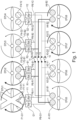
- FIG. 1 shows schematically an example embodiment of a DC multilane power distribution system, wherein the system comprises a plurality of power sources G1, G2, Y1, Y2, B1, B2, R1, R2 and a plurality of load devices EPU 1 to EPU 8 which are connected through a DC distribution system.
- the system may be used in hybrid propulsion system applications.
- the power sources G1, G2, Y1, Y2, B1, B2, R1, R2 may be or comprise batteries and are, in the following, referred to as batteries, without limiting the power sources to batteries.
- the power sources may alternatively be fuel cells or a rectifier extracting power from a turbo generator.
- the load devices EPU 1 to EPU 8 may be electronic propulsion units (EPUs) and are, in the following, referred to as EPUs, without limiting the load devices two EPUs.
- each battery G1, G2, Y1, Y2, B1, B2, R1, R2 powers two EPUs.
- battery G1 powers EPU 1 and EPU 6.
- battery G2 powers EPU 4 and EPU 7.
- each of the EPUs EPU 1 to EPU 8 is powered by two of the batteries G1, G2, Y1, Y2, B1, B2, R1, R2.
- EPU 1 is powered by battery G1 and by battery Y1.
- EPU 2 is powered by battery R1 and battery B1.
- EPU 3 is powered by battery R2 and by battery B2, etc.
- batteries G1, G2 are assigned to each other. They can be connected through a contactor 14 which connects the respective power buses (also referred to as lanes) PB-G1, PB-G2.
- batteries Y1, Y2 are assigned to each other. They can be connected through a contactor 13 which connects the respective power busses PB-Y1, PB-Y2. Further, batteries R1, R2 are assigned to each other. They can be connected through a contactor 12 which connects the respective power buses PB-R1, PB-R2. Also, batteries B1, B2 are assigned to each other. They can be connected through a contactor 11 which connects the respective power buses PB-B1, PB-B2.
- the power busses PB-G1/2, PB-Y1/2, PB-B1/2, PB-R1/2 form a DC distribution network, wherein two associated batteries and their corresponding lanes/power buses (such as batteries G1, G2 and power buses PB-G1, PB-G2) form a sub-distribution system within the overall DC distribution system.
- each power bus comprises a high side voltage rail connected to a positive batterie voltage and a low side voltage rail connected to a negative batterie voltage, as will be seen, e.g., in Figures 2 and 8.
- the contactors 11-14 each comprise a contactor for the high side voltage rail and a contactor for the low side voltage rail, as will also be seen, e.g., in Figures 2 and 8. When two batteries are connected, the high side voltage rails are connected and the low side voltage rails are connected (parallel connection).
- the network of Figure 1 represents an example network only. Other network configurations may be implemented as well.
- three or more of the batteries are assigned to each other in the sense that they may be electrically connected to each other.
- the architecture may include a ring architecture, wherein two or more than two batteries are connected at given time.
- Each of the EPUs EPU 1 to EPU 8 comprises two electrical motors.
- EPU 1 comprises electric motor F1-G1 which is driven by battery G1 through a power converter/inverter (not shown).
- EPU 1 further comprises electric motor F1-Y1 which is driven by battery Y1 through another power converter/inverter (not shown).
- the power converters each provide for a three phase alternating current which drives the respective electric motors F1-G1 and F1-Y1.
- the electric motors such as electric motors F1-G1 and F1-Y1 may be two physically different machines connected to the same shaft, or maybe two sets of windings wound in the same machine, each fed by a different power converter.
- each of the other EPUs EPU 2-8 comprise two electrical motors F2-R1, F2-B1, F3-R2, F3-B2, F4-G2, F4-Y2, A1-R1, A1-B1, A2-G1, A1-Y1, A3-G2, A3-Y2, A4-R2, A4-B2, and corresponding power converters as well.
- the EPUs may include propellers, wherein some of the propellers turn in one direction and the same number of propellers turn in the other direction, such as is used in e-VTOLs.
- propellers wherein some of the propellers turn in one direction and the same number of propellers turn in the other direction, such as is used in e-VTOLs.
- the lanes are kept independent whereas under certain conditions it is preferable that lanes are connected to allow sharing of power from the batteries.
- FIG 1 it is schematically illustrated as an example that EPU 1 fails. In such case, it is sensible to diverge the energies of the batteries G1, Y1 to some of other EPUs by closing contactors 13 and 14.
- batteries which are associated and together form a sub-distribution system such as electrically connecting batteries G1, G2 through contactor 14 or batteries Y1, Y2 through contactor 13.
- a sub-distribution system such as electrically connecting batteries G1, G2 through contactor 14 or batteries Y1, Y2 through contactor 13.
- sharing energy stored in batteries is not straightforward, and different batteries will be discharged differently and will, therefore, have different voltages at the time they are connected. When batteries are connected that have different voltages, this would result in unwanted inrush current and/or current flowing among the batteries.
- load capacities present or associated with the loads of the batteries, wherein such load capacities may also cause an inrush current.
- FIG. 2 depicts a sub-distribution system of the distribution system of Figure 1 in accordance with the present invention.
- the sub-distribution system comprises batteries G1, G2 and EPUs EPU 1 and EPU 4 as depicted in Figure 1 .
- a power bus PB-G1 connected to battery G1 comprises a high side voltage rail PB-G1-H and a low side voltage rail PB-G1-L.
- a power bus PB-G2 connected to battery G2 comprises a high side voltage rail PB-G2-H and a low side voltage rail PB-G2-L.
- a pulse-width modulated switch SSPC 14 which is implemented as an SSPC and which connects the high side voltage rails PB-G1-H, PB-G2-H in accordance with its duty cycle. Further, there is provided a contactor 14-L which connects the low side voltage rails PB-G1-L, PB-G2-L.
- the SSPC 14-SSPC may also be referred to as bus-tie SSPC and the contactor 14-L may also be referred to as bus-tie contactor.
- FIG. 2 further shows filtering capacities C DC-1 , C DC-4 between the respective high side voltage rails and low side voltage rails.
- the voltage rails with mounted filtering capacitors C DC and connected to the battery G1, G2 are often termed as DC link and the filtering capacitors C DC are termed as DC link capacitors which are meant to filter any AC noise present in the DC line mainly when operating at higher voltage levels.
- the filtering capacitors C DC and, possibly, further capacitors within or associated with the load provide for a capacitive load which provide for a high inrush current in the power buses PB-G1, PB-G2 are connected by contactors only.
- an inrush current may be produced by a different voltage the batteries G1, G2 present before the contactors 14-H, 14-L are closed.
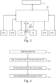
- FIG 3 shows a system design in which a control unit 20 controls operation of the batteries, the EPUs and the switching elements.
- a control unit 20 controls operation of the batteries, the EPUs and the switching elements.
- the batteries G1, G2 for simplicity, only two of the batteries G1, G2, the contactors 14-SSPC and 14-L connecting these batteries G1, G2, and the EPUs which are driven by these batteries (EPUs 1, 6, 4 and 7 in accordance with Figure 1 ) are shown, wherein all the batteries, EPUs, corresponding converters and electric motors and switchable elements communicate with the control unit 20.
- the control unit 20 may further communicate with an aircraft controller 10.
- the batteries G1, G2 provide information to the control unit 20 such as voltage, current and temperature.
- Battery G1 powers EPU 1 and EPU 6.
- battery G2 powers EPU 4 and EPU 7.
- the control unit 20 also controls operation of the EPUs and the amount of energy provided to the EPUs.
- the control unit 20 further controls whether two batteries such as batteries G1, G2 are to be connected. To this end, the control unit 20 provides control signals S1, S2 to the SSPC 14-SSPC and the contactor 14-L.
- the control signal S1 to the contactor regards the state of the contactor, i.e., whether the contactor is switched on (closed) or is switched off (opened).
- the initial value of the duty cycle may be very low and be, e.g., in the range between 0.1% and 10%.
- the SSPC guides current only intermittently in accordance with the pulse width modulation, the current passing the SSPC is highly limited at the beginning of the transitional period, thereby preventing the presence of an inrush current.
- step 43 the duty cycle increases.
- the increase may be linearly or non-linearly such as in steps.
- the course of the increase is programmed.
- step 44 the duty cycle reaches 100%, step 44, at which point the respective power buses are fully collected.
Landscapes
- Engineering & Computer Science (AREA)
- Power Engineering (AREA)
- Direct Current Feeding And Distribution (AREA)
Abstract
A multilane power distribution system which comprises a plurality of DC power sources (G1, G2, Y1, Y2, B1, B2, R1, R2) and a plurality of load devices (EPU 1-8), wherein each DC power source (G1, G2, Y1, Y2, B1, B2, R1, R2) powers at least two of the load devices (EPU 1-8), and each of the load devices (EPU 1-8) is powered by at least two of the DC power sources (G1, G2, Y1, Y2, B1, B2, R1, R2). The system further comprises a DC connection network, the DC connection network comprising power buses for connecting the DC power sources (G1, G2, Y1, Y2, B1, B2, R1, R2) and the load devices (EPU 1-8), the power buses having a high side voltage rail (PB-G1-H, PB-G2-H) for the positive voltage and a low side voltage rail (PB-G1-L, PB-G2-L) for the negative voltage. At least two of the power buses (G1, G2, Y1, Y2, B1, B2, R1, R2) are connectable by switchable elements (11-14, 14-SSPC, 14-L), namely, a first switchable element (14-SSPC) for the high side voltage rails (PB-G1-H, PB-G2-H) and a second switchable element (14-L) for the low side voltage rails (PB-G1-L, PB-G2-L), the switchable elements (14-SSPC, 14-L) when switched on electrically connecting the terminals of two of the DC power sources (G1, G2) connected by the respective power buses (PB-G1, PB-G2). It is provided that one of the switchable elements is a pulse-width modulated switch (14-SSPC), wherein the pulse-width modulated switch (14-SSPC) electrically connects the respective voltage rails (PB-G1-H, PB-G2-H) in accordance with the pulse-width modulation.
Description
- The present disclosure relates to a multilane power distribution system, in particular for aerospace DC power systems.
- In aircraft DC power distribution systems it is known to implement multiple energy sources such as multiple batteries or fuel cells and multiple loads such as electric propulsion units (EPUs). The multiple loads and sources may be connected through a DC distribution system using a multilane architecture, meaning that the DC distribution system comprises a plurality of power buses.
- The multilane architecture provides for the possibility that different lanes are connected to allow sharing of power from the batteries and/or to provide for redundancy. However, when batteries are connected, this may result in unwanted inrush current and/or a current flowing among batteries. In particular, an initial current transient of a different voltage bus can trigger a battery pack main protection, cause battery thermal runaway and/or melt battery cell connections.
- There is a need to provide a method for controlling a multilane power distribution system that allows to connect batteries or other DC power sources of such power distribution system in an efficient manner that addresses the aforementioned problems or at least provides a useful alternative to known multilane power distribution systems.
- The present disclosure provides a multilane power distribution system as set out in the appended claims.
- In a first aspect a multilane power distribution system is provided. The multilane power distribution system comprises a plurality of DC power sources and a plurality of load devices, wherein each DC power source powers at least two of the load devices, and wherein each of the load devices is powered by at least two of the DC power sources. The multilane power distribution system further comprises a DC connection network, the DC connection network comprising power buses for connecting the DC power sources and the load devices, the power buses having a high side voltage rail for the positive voltage and a low side voltage rail for the negative voltage. At least two of the power buses are connectable by switchable elements, namely, a first switchable element for the high side voltage rails and a second switchable element for the low side voltage rails, the switchable elements when switched on electrically connecting the terminals of two of the DC power sources connected by the respective power buses.
- It is provided that one of the switchable elements is a pulse-width modulated switch, wherein the pulse-width modulated switch electrically connects the respective voltage rails in accordance with the pulse-width modulation.
- Aspects of the invention are thus based on the idea to provide for a pulse-width modulated switch, wherein the pulse-width modulated switch limits any inrush current when the two DC power sources are connected. The pulse-width modulated switch can control any inrush current through its duty cycle, and thereby keep the initial current within safe limits of a DC power source protection such as a battery pack protection.
- A further advantage associated with the present invention lies in that the pulse-width modulated switch allows the voltage levels of the two DC power sources and/or of capacitive loads connected to the DC power sources to slowly align with each other, wherein, after such alignment, the pulse-width modulated switch may operate with a 100% duty cycle (fully closed).
- In some embodiments it is the first switchable element that that connects the high side voltage rails which is a pulse-width modulated switch.
- In some embodiments the other switchable element is a contactor. This is associated with the advantage that a full galvanic isolation of the respective positive and negative lanes can be achieved. A contactor is controlled by a circuit which has a much lower power level than the switched circuit. A contactor knows two switching positions and is typically monostable, wherein bi-stable contactors may be provided as well in embodiments of the invention. Typically, a contactor is activated by electromagnets. For example, when a control current flows through a solenoid coil of an electromechanical contactor, the magnetic field pulls the mechanical contacts into the active state. Without current, a spring restores the idle state and all contacts return to their initial position. The connections for control current for the solenoid coil as well as the contacts for auxiliary circuits (if any) and currents to be switched are isolated from each other in the contactor. There is no conductive connection between control and switching contacts. Such contactors are well known to the skilled person.
- In some embodiments the system further includes a control unit which controls the state of the first and second switchable elements. In particular, the control unit may be configured to control the pulse-width modulated switch such that the duty cycle of the pulse-width modulated switch: is 0 % before the DC power sources are connected; is between 0% and 100% in a transitional period after the voltage rails are being connected, wherein the duty cycle increases over time during the transitional period; and is 100% after the transitional period, when the two DC power sources are fully connected.
- By changing the duty cycle within the transitional period, it is possible to limit any inrush current in an efficient manner, wherein at the beginning of the transitional period the duty cycle is small (e.g., within 0.1% and 10%) such that the periods in which the respective lanes are connected is short, this implying that the amount of current which passes the switch is highly limited. Within time, when the voltage difference over the switch decreases and the voltage levels align, the duty cycle can be increased.
- The change of the duty cycle within the transitional period can be adapted to the circumstances. In some embodiments the control unit is configured to control the pulse-width modulated switch such that the duty cycle of the pulse-width modulated switch rises linearly during the transitional period. However, a linear increase of the duty cycle within the transitional period is to be understood as an example only. In some embodiments there may be provided for a nonlinear development. For example, the duty cycle may increase at the beginning of the transitional period only very slowly and increase towards the end of the transitional faster. In another example, the duty cycle is increased in the steps.
- In some embodiments it may be provided that the control unit is configured to control the pulse-width modulated switch such that the initial duty cycle of the pulse-width modulated switch in the transitional period depends on the initial voltage difference over the pulse-width modulated switch. If the initial voltage difference is high, the initial duty cycle in the transitional period can be chosen to be smaller compared to the situation in which the initial voltage difference is low.
- It may be provided for that all DC power sources, all switchable elements and all load devices are centrally controlled by the control unit. Such central control unit oversees controlling and commanding of each of DC power sources and the load devices, thereby being able to connect particular DC power sources in case need arises (such as when one of the load devices fails). Such central control unit may also consider other parameters such as a mission profile and load demands.
- In some embodiments the pulse-width modulated switch is a solid state power controller (SSPC). Due to the fact that SSPCs show, e.g., a fast response time, eliminate arcing during turn-off, and have a high reliability, SSPCs are preferred switches. Also, SSPCs allow to combine the function of connecting batteries and loads to a DC power bus with the function of protecting electrical installations against overload and short circuits.
- However, in principle, any other switches the pulse-width of which may be modulated may be used as well.
- Generally, it may be provided that each DC power source powers at least two of the load devices through a respective power converter such as an inverter, wherein each power converter drives one of the load devices.
- In some embodiments the DC connection network is configured such that one considered DC power source is connectable to one other DC power source only, such that there is at least one pair of associated DC power sources, wherein two DC power sources which are connectable are connectable through the switchable elements.
- According to such embodiments, there are provided pairs of associated DC power sources which may be connected through a switchable element. It is thus provided that a particular DC power source can be electrically connected to a particular associated DC power source only, and not to any of the other DC power sources of the system. Such bidirectional association is associated with the advantage that a central control is simplified as two DC power sources have to be considered only when readjusting DC power source connections.
- In some embodiments the DC power source comprises an electric battery. However, the present invention is not limited to such embodiments. For example, there may be provided fuel cells as DC power sources, a mixture of batteries and fuel cells, or a turbo generator/active rectifier.
- In some embodiments the load device comprises an electric motor. However, the present invention is not limited to such embodiments. For example, other load devices such as pumps may be provided for.
- One application of the present invention lies in electric Vertical Take Off and Landing aircrafts (e-VTOLs). During take-off and landing the propulsion system of e-VTOLs is at its limit. E-VTOLs use several independent engines that provide for redundancy. A DC Electric Power Distribution Unit (which is a control unit) distributes and connects the energy sources to the loads. One of the functions of the distribution unit is to connect multiple energy sources, e.g., in case of an engine failure.
- The skilled person will appreciate that except where mutually exclusive, a feature or parameter described in relation to any one of the above aspects may be applied to any other aspect. Furthermore, except where mutually exclusive, any feature or parameter described herein may be applied to any aspect and/or combined with any other feature or parameter described herein.
- The invention will be explained in more detail on the basis of exemplary embodiments with reference to the accompanying drawings in which:
-
Figure 1 shows an embodiment of multilane power distribution system comprising multiple batteries and multiple electronic propulsion units, wherein two associated lanes and batteries may be electrically connected through contactors; -
Figure 2 is an embodiment of a sub-distribution system of the distribution system ofFigure 1 , wherein the sub-distribution system comprises two batteries connected through a power line that has a high side voltage rail and a low side voltage rail, wherein the subsystem further comprises an SSPC in the high side voltage rail and a contactor in the low side voltage rail; -
Figure 3 shows an embodiment of a control system for controlling a multilane power distribution system such as the system ofFigure 1 ; -
Figure 4 is a flowchart of a method for controlling the SSPC ofFigure 2 , wherein the duty cycle of the SSPC is increased in a transitional period; and -
Figure 5 is a diagram showing schematically different duty cycles within the transitional period ofFigure 4 . - With increased penetration of electrical systems and the progression towards full electric and hybrid propulsion systems, the use of DC multilane power distribution systems has gained increased use.
Figure 1 shows schematically an example embodiment of a DC multilane power distribution system, wherein the system comprises a plurality of power sources G1, G2, Y1, Y2, B1, B2, R1, R2 and a plurality of load devices EPU 1 to EPU 8 which are connected through a DC distribution system. Such system may be used in hybrid propulsion system applications. - The power sources G1, G2, Y1, Y2, B1, B2, R1, R2 may be or comprise batteries and are, in the following, referred to as batteries, without limiting the power sources to batteries. For example, in aerospace applications, the power sources may alternatively be fuel cells or a rectifier extracting power from a turbo generator. The load devices EPU 1 to EPU 8 may be electronic propulsion units (EPUs) and are, in the following, referred to as EPUs, without limiting the load devices two EPUs.
- The architecture of the multilane power distribution system of
Figure 1 implements redundancy and power sharing aspects as follows:
First, each battery G1, G2, Y1, Y2, B1, B2, R1, R2 powers two EPUs. For example, battery G1 powers EPU 1 and EPU 6. In another example, battery G2 powersEPU 4 and EPU 7. - Second, each of the EPUs EPU 1 to EPU 8 is powered by two of the batteries G1, G2, Y1, Y2, B1, B2, R1, R2. For example, EPU 1 is powered by battery G1 and by battery Y1. EPU 2 is powered by battery R1 and battery B1. EPU 3 is powered by battery R2 and by battery B2, etc.
- Third, two of the batteries are assigned to each other in the sense that a particular of the batteries can be electrically connected to another one of the batteries, wherein each battery can be connected to one associated other battery only. For example, batteries G1, G2 are assigned to each other. They can be connected through a
contactor 14 which connects the respective power buses (also referred to as lanes) PB-G1, PB-G2. - In a similar manner, batteries Y1, Y2 are assigned to each other. They can be connected through a
contactor 13 which connects the respective power busses PB-Y1, PB-Y2. Further, batteries R1, R2 are assigned to each other. They can be connected through acontactor 12 which connects the respective power buses PB-R1, PB-R2. Also, batteries B1, B2 are assigned to each other. They can be connected through acontactor 11 which connects the respective power buses PB-B1, PB-B2. - The power busses PB-G1/2, PB-Y1/2, PB-B1/2, PB-R1/2 form a DC distribution network, wherein two associated batteries and their corresponding lanes/power buses (such as batteries G1, G2 and power buses PB-G1, PB-G2) form a sub-distribution system within the overall DC distribution system.
- It is pointed out that each power bus comprises a high side voltage rail connected to a positive batterie voltage and a low side voltage rail connected to a negative batterie voltage, as will be seen, e.g., in
Figures 2 and 8. It is further pointed out that the contactors 11-14 each comprise a contactor for the high side voltage rail and a contactor for the low side voltage rail, as will also be seen, e.g., inFigures 2 and 8. When two batteries are connected, the high side voltage rails are connected and the low side voltage rails are connected (parallel connection). - It is further pointed out that the network of
Figure 1 represents an example network only. Other network configurations may be implemented as well. For example, in other embodiments, three or more of the batteries are assigned to each other in the sense that they may be electrically connected to each other. In another example, the architecture may include a ring architecture, wherein two or more than two batteries are connected at given time. - Each of the EPUs EPU 1 to EPU 8 comprises two electrical motors. For example, EPU 1 comprises electric motor F1-G1 which is driven by battery G1 through a power converter/inverter (not shown). EPU 1 further comprises electric motor F1-Y1 which is driven by battery Y1 through another power converter/inverter (not shown). For example, the power converters each provide for a three phase alternating current which drives the respective electric motors F1-G1 and F1-Y1. In this respect, it is pointed out that the electric motors such as electric motors F1-G1 and F1-Y1 may be two physically different machines connected to the same shaft, or maybe two sets of windings wound in the same machine, each fed by a different power converter.
- In a similar manner, each of the other EPUs EPU 2-8 comprise two electrical motors F2-R1, F2-B1, F3-R2, F3-B2, F4-G2, F4-Y2, A1-R1, A1-B1, A2-G1, A1-Y1, A3-G2, A3-Y2, A4-R2, A4-B2, and corresponding power converters as well.
- In the depicted embodiment, the EPUs may include propellers, wherein some of the propellers turn in one direction and the same number of propellers turn in the other direction, such as is used in e-VTOLs. However, this represents an embodiment only.
- During certain mission profiles, the lanes are kept independent whereas under certain conditions it is preferable that lanes are connected to allow sharing of power from the batteries. For example, in
Figure 1 it is schematically illustrated as an example that EPU 1 fails. In such case, it is sensible to diverge the energies of the batteries G1, Y1 to some of other EPUs by closingcontactors - Accordingly, it is beneficial under certain conditions, for example during a failure condition, to electrically connect batteries which are associated and together form a sub-distribution system, such as electrically connecting batteries G1, G2 through
contactor 14 or batteries Y1, Y2 throughcontactor 13. However, sharing energy stored in batteries is not straightforward, and different batteries will be discharged differently and will, therefore, have different voltages at the time they are connected. When batteries are connected that have different voltages, this would result in unwanted inrush current and/or current flowing among the batteries. - Further, as will be discussed with respect to
Figure 2 , there may be load capacities present or associated with the loads of the batteries, wherein such load capacities may also cause an inrush current. -
Figure 2 depicts a sub-distribution system of the distribution system ofFigure 1 in accordance with the present invention. The sub-distribution system comprises batteries G1, G2 and EPUs EPU 1 andEPU 4 as depicted inFigure 1 . A power bus PB-G1 connected to battery G1 comprises a high side voltage rail PB-G1-H and a low side voltage rail PB-G1-L. In a similar manner, a power bus PB-G2 connected to battery G2 comprises a high side voltage rail PB-G2-H and a low side voltage rail PB-G2-L. - In between the voltage rails is provided a pulse-width modulated
switch SSPC 14 which is implemented as an SSPC and which connects the high side voltage rails PB-G1-H, PB-G2-H in accordance with its duty cycle. Further, there is provided a contactor 14-L which connects the low side voltage rails PB-G1-L, PB-G2-L. The SSPC 14-SSPC may also be referred to as bus-tie SSPC and the contactor 14-L may also be referred to as bus-tie contactor. - It is pointed out that the batteries G1, G2 contact through the voltage rails also the EPUs EPU 1 and
EPU 4, respectively.Figure 2 further shows filtering capacities CDC-1, CDC-4 between the respective high side voltage rails and low side voltage rails. The voltage rails with mounted filtering capacitors CDC and connected to the battery G1, G2 are often termed as DC link and the filtering capacitors CDC are termed as DC link capacitors which are meant to filter any AC noise present in the DC line mainly when operating at higher voltage levels. The filtering capacitors CDC and, possibly, further capacitors within or associated with the load, provide for a capacitive load which provide for a high inrush current in the power buses PB-G1, PB-G2 are connected by contactors only. In addition, an inrush current may be produced by a different voltage the batteries G1, G2 present before the contactors 14-H, 14-L are closed. - To avoid the presence of an inrush current when the two batteries G1, G2 are connected through the switchable elements 14-SSPC, 14-L, wherein the duty cycle of the SSPC is controlled in a specific manner by a control unit, as is discussed with respect to
Figure 3 . -
Figure 3 shows a system design in which acontrol unit 20 controls operation of the batteries, the EPUs and the switching elements. InFigure 3 , for simplicity, only two of the batteries G1, G2, the contactors 14-SSPC and 14-L connecting these batteries G1, G2, and the EPUs which are driven by these batteries (EPUs 1, 6, 4 and 7 in accordance withFigure 1 ) are shown, wherein all the batteries, EPUs, corresponding converters and electric motors and switchable elements communicate with thecontrol unit 20. Thecontrol unit 20 may further communicate with anaircraft controller 10. - More particularly, in
Figure 3 , the batteries G1, G2 provide information to thecontrol unit 20 such as voltage, current and temperature. Battery G1 powers EPU 1 and EPU 6. In a similar manner, battery G2 powersEPU 4 and EPU 7. Thecontrol unit 20 also controls operation of the EPUs and the amount of energy provided to the EPUs. - The
control unit 20 further controls whether two batteries such as batteries G1, G2 are to be connected. To this end, thecontrol unit 20 provides control signals S1, S2 to the SSPC 14-SSPC and the contactor 14-L. The control signal S1 to the contactor regards the state of the contactor, i.e., whether the contactor is switched on (closed) or is switched off (opened). - The control signal S2 to the SSPC defines the duty cycle of the SSPC. A typical control sequence is depicted in
Figure 4 . According toFigure 4 , instep 41, the initial duty cycle is 0%, i.e., the SSPC is switched off and no current can flow through the SSPC. If the batteries G1, G2 shall be electrically connected, a transitional period is implemented in which the duty cycle rises to 100%. More particularly, at the beginning of the transitional period, the duty cycle is set to a value larger than 0%,step 42. This initial value may depend on the voltage difference over the respective voltage rails PB-G1-H and PB-G2-H. The initial value of the duty cycle may be very low and be, e.g., in the range between 0.1% and 10%. As the SSPC guides current only intermittently in accordance with the pulse width modulation, the current passing the SSPC is highly limited at the beginning of the transitional period, thereby preventing the presence of an inrush current. - During the transitional period, the duty cycle increases,
step 43. The increase may be linearly or non-linearly such as in steps. The course of the increase is programmed. At the end of the transitional period, the duty cycle reaches 100%,step 44, at which point the respective power buses are fully collected. - The contactor 14-L may be switched on at the beginning or shortly before the beginning of the transitional period.
-
Figure 5 shows examples of different duty cycles which may be implemented by the SSPC 14-SSPC under the control of thecontrol unit 20. When the duty cycle is at 0%, the SSPC is permanently opened such that no current can flow through the SSPC. If the duty cycle is at 25%, the SSPC is switched on for 25% of the time period T and thus guiding current for 25% percent of the time. This relation may increase to 50 percent and 75 percent. When the duty cycle is 100%, the SSPC is fully closed and thus guiding current constantly. - The use of an SSPC as one of the switches that connect the voltage rails PB-G1 and PB-G2 and thus the respective batteries G1, G2 allows to limit the inrush current due to the interrupted time periods in which the SSPC is guiding current in accordance with the applied pulse-width modulation/duty cycle.
- It should be understood that the above description is intended for illustrative purposes only, and is not intended to limit the scope of the present disclosure in any way. Also, those skilled in the art will appreciate that other aspects of the disclosure can be obtained from a study of the drawings, the disclosure and the appended claims. All methods described herein can be performed in any suitable order unless otherwise indicated herein or otherwise clearly contradicted by context. Various features of the various embodiments disclosed herein can be combined in different combinations to create new embodiments within the scope of the present disclosure. In particular, the disclosure extends to and includes all combinations and sub-combinations of one or more features described herein. Any ranges given herein include any and all specific values within the range and any and all sub-ranges within the given range.
Claims (12)
- A multilane power distribution system comprising:a plurality of DC power sources (G1, G2, Y1, Y2, B1, B2, R1, R2);a plurality of load devices (EPU 1-8), wherein each DC power source (G1, G2, Y1, Y2, B1, B2, R1, R2) powers at least two of the load devices (EPU 1-8), and each of the load devices (EPU 1-8) is powered by at least two of the DC power sources (G1, G2, Y1, Y2, B1, B2, R1, R2); anda DC connection network, the DC connection network comprising power buses (PB-G1/2, PB-Y1/2, PB-B1/2, PB-R1/2) for connecting the DC power sources (G1, G2, Y1, Y2, B1, B2, R1, R2) and the load devices (EPU 1-8), the power buses having a high side voltage rail (PB-G1-H, PB-G2-H) for the positive voltage and a low side voltage rail (PB-G1-L, PB-G2-L) for the negative voltage;wherein at least two of the power buses (G1, G2, Y1, Y2, B1, B2, R1, R2) are connectable by switchable elements (11-14, 14-SSPC, 14-L), namely, a first switchable element (14-SSPC) for the high side voltage rails (PB-G1-H, PB-G2-H) and a second switchable element (14-L) for the low side voltage rails (PB-G1-L, PB-G2-L), the switchable elements (14-SSPC, 14-L) when switched on electrically connecting the terminals of two of the DC power sources (G1, G2) connected by the respective power buses (PB-G1, PB-G2); andwherein one of the switchable elements is a pulse-width modulated switch (14-SSPC), wherein the pulse-width modulated switch (14-SSPC) electrically connects the respective voltage rails (PB-G1-H, PB-G2-H) in accordance with the pulse-width modulation.
- The multilane power distribution system of claim 1, wherein the first switchable element is a pulse-width modulated switch (14-SSPC).
- The multilane power distribution system of claim 1 or 2, wherein the other switchable element is a contactor (14-L).
- The multilane power distribution system of any preceding claim, wherein a control unit (20) controlling the state of the first switchable element (14-SSPC) and the second switchable element (14-L).
- The multilane power distribution system of claim 5, wherein the control unit (20) is configured to control the pulse-width modulated switch (14-SSPC) such that the duty cycle of the pulse-width modulated switch (14-SSPC):is 0 % before the DC power sources (G1, G2) are connected;is between 0% and 100% in a transitional period after the voltage rails (PB-G1-H, PB-G2-H) are being connected, wherein the duty cycle increases over time during the transitional period; andis 100% after the transitional period, when the two DC power sources are fully connected.
- The multilane power distribution system of claim 5, wherein the control unit (20) is configured to control the pulse-width modulated switch (14-SSPC) such that the initial duty cycle of the pulse-width modulated switch (14-SSPC) in the transitional period depends on the initial voltage difference over the pulse-width modulated switch (14-SSPC).
- The multilane power distribution system of claim 5 or 6, wherein the control unit (20) is configured to control the pulse-width modulated switch (14-SSPC) such that the duty cycle of the pulse-width modulated switch (14-SSPC) rises linearly during the transitional period.
- The multilane power distribution system of any one of claims 5 to 7, wherein all DC power sources (G1, G2, Y1, Y2, B1, B2, R1, R2), all switchable elements (11-14, 14-SSPC, 14-L) and all load devices (EPU 1-8) are centrally controlled by the control unit (20).
- The multilane power distribution system of any preceding claim, wherein the pulse-width modulated switch is a solid state power controller.
- The multilane power distribution system of any preceding claim, wherein each DC power source (G1, G2, Y1, Y2, B1, B2, R1, R2) powers at least two of the load devices (EPU 1-8) through a respective power converter (F1-G1, F1-Y1, F2-R1, F2-B1, F3-R2, F3-B2, F4-G2, F4-Y2, A1-R1, A1-B1, A2-G1, A2-Y1, A3-G2, A3-Y2, A4-R2, A4-B2), wherein each power converter drives one of the load devices (EPU 1-8).
- The multilane power distribution system of any preceding claim, wherein the DC connection network is configured such that one considered DC power source (G1, Y1, B1, R1) is connectable to one other DC power source (G2, Y2, B2, R2) only, such that there is at least one pair of associated DC power sources (G1, G2, Y1, Y2, B1, B2, R1, R2), wherein two DC power sources (Y1, Y2, G1, G2, B1, B2, R1, R2) which are connectable are connectable through the switchable elements (11-14, 14-SSPC, 14-L).
- The multilane power distribution system of any preceding claim, wherein the DC power source (G1, G2, Y1, Y2, B1, B2, R1, R2) comprises an electric battery and/or the load device (EPU 1-8) comprises an electric motor.
Applications Claiming Priority (1)
| Application Number | Priority Date | Filing Date | Title |
|---|---|---|---|
| GBGB2311376.4A GB202311376D0 (en) | 2023-07-25 | 2023-07-25 | Multilane power distribution system |
Publications (1)
| Publication Number | Publication Date |
|---|---|
| EP4498552A1 true EP4498552A1 (en) | 2025-01-29 |
Family
ID=87851935
Family Applications (1)
| Application Number | Title | Priority Date | Filing Date |
|---|---|---|---|
| EP24182305.3A Withdrawn EP4498552A1 (en) | 2023-07-25 | 2024-06-14 | Multilane power distribution system |
Country Status (3)
| Country | Link |
|---|---|
| US (1) | US20250038666A1 (en) |
| EP (1) | EP4498552A1 (en) |
| GB (1) | GB202311376D0 (en) |
Citations (8)
| Publication number | Priority date | Publication date | Assignee | Title |
|---|---|---|---|---|
| US20090091187A1 (en) * | 2006-04-05 | 2009-04-09 | Thales | Device for Powering a Plurality of Loads from an Electrical Power Supply Network |
| US20130234508A1 (en) * | 2010-12-01 | 2013-09-12 | Zf Friedrichshafen Ag | Apparatus for use in an electrical drive system, and method for operating an apparatus of this kind |
| EP3421287A1 (en) * | 2017-06-28 | 2019-01-02 | Fico Triad, S.A. | Battery connection system for electric and/or hybrid vehicles |
| WO2019211810A1 (en) * | 2018-05-04 | 2019-11-07 | H55 Sa | Aircraft monitoring system and method for electric or hybrid aircrafts |
| EP3611045A1 (en) * | 2017-04-14 | 2020-02-19 | Hitachi Construction Machinery Co., Ltd. | Electricity storage device controller, electric system, and construction machine |
| EP3699090A1 (en) * | 2019-02-22 | 2020-08-26 | Aurora Flight Sciences Corporation | Programmable battery pack |
| US20220204173A1 (en) * | 2019-04-25 | 2022-06-30 | Safran Helicopter Engines | Aircraft electrical energy supply network |
| US11465532B2 (en) * | 2021-01-22 | 2022-10-11 | Archer Aviation, Inc. | Systems and methods for power distribution in electric aircraft |
-
2023
- 2023-07-25 GB GBGB2311376.4A patent/GB202311376D0/en not_active Ceased
-
2024
- 2024-06-14 EP EP24182305.3A patent/EP4498552A1/en not_active Withdrawn
- 2024-06-18 US US18/746,677 patent/US20250038666A1/en active Pending
Patent Citations (8)
| Publication number | Priority date | Publication date | Assignee | Title |
|---|---|---|---|---|
| US20090091187A1 (en) * | 2006-04-05 | 2009-04-09 | Thales | Device for Powering a Plurality of Loads from an Electrical Power Supply Network |
| US20130234508A1 (en) * | 2010-12-01 | 2013-09-12 | Zf Friedrichshafen Ag | Apparatus for use in an electrical drive system, and method for operating an apparatus of this kind |
| EP3611045A1 (en) * | 2017-04-14 | 2020-02-19 | Hitachi Construction Machinery Co., Ltd. | Electricity storage device controller, electric system, and construction machine |
| EP3421287A1 (en) * | 2017-06-28 | 2019-01-02 | Fico Triad, S.A. | Battery connection system for electric and/or hybrid vehicles |
| WO2019211810A1 (en) * | 2018-05-04 | 2019-11-07 | H55 Sa | Aircraft monitoring system and method for electric or hybrid aircrafts |
| EP3699090A1 (en) * | 2019-02-22 | 2020-08-26 | Aurora Flight Sciences Corporation | Programmable battery pack |
| US20220204173A1 (en) * | 2019-04-25 | 2022-06-30 | Safran Helicopter Engines | Aircraft electrical energy supply network |
| US11465532B2 (en) * | 2021-01-22 | 2022-10-11 | Archer Aviation, Inc. | Systems and methods for power distribution in electric aircraft |
Also Published As
| Publication number | Publication date |
|---|---|
| GB202311376D0 (en) | 2023-09-06 |
| US20250038666A1 (en) | 2025-01-30 |
Similar Documents
| Publication | Publication Date | Title |
|---|---|---|
| CN110168842B (en) | Battery system | |
| US7800254B2 (en) | System for bypassing a power cell of a power supply | |
| US9197088B2 (en) | Module for converting voltage between a high-voltage electrical network of an aircraft and an energy storage element | |
| US6917181B2 (en) | Power supply unit, distributed power supply system and electric vehicle loaded therewith | |
| KR101670002B1 (en) | Battery system, motor vehicle having a battery system, and method for starting up a battery system | |
| US8008923B2 (en) | Method for bypassing a power cell of a power supply | |
| JP6178328B2 (en) | DC voltage source including an electrochemical cell | |
| EP3421287A1 (en) | Battery connection system for electric and/or hybrid vehicles | |
| US12542478B2 (en) | Voltage regulation module, charging module, and charging pile | |
| US20140084864A1 (en) | Method for Charging a Battery | |
| CN116788112B (en) | Power battery system, electric automobile and power battery system control method | |
| KR100630210B1 (en) | Submarine | |
| US20250038666A1 (en) | Multilane power distribution system | |
| EP4425729A1 (en) | Vehicle power supply system and vehicle comprising same | |
| EP3696931A1 (en) | Dual active bridge energy storage module systems | |
| EP4498551A1 (en) | Multilane power distribution system | |
| EP4322353A1 (en) | Electrical arrangement for direct current electric systems | |
| CN116054576B (en) | Energy system for electric vehicle | |
| CN119968748A (en) | DC transformer arrangement, energy supply system and method for discharging an intermediate circuit capacitor | |
| WO2023080793A1 (en) | A circuit module for controlling a plurality of energy cell units | |
| EP4102678B1 (en) | Multi-functional current limiter for energy storage devices | |
| CN222654869U (en) | Power circuit and airborne power system | |
| JP5077489B2 (en) | Power storage device and railway vehicle | |
| CN119483225A (en) | AC to DC device and charging pile | |
| CN118238618A (en) | Circuit arrangement for disconnecting a rechargeable battery from an inverter |
Legal Events
| Date | Code | Title | Description |
|---|---|---|---|
| PUAI | Public reference made under article 153(3) epc to a published international application that has entered the european phase |
Free format text: ORIGINAL CODE: 0009012 |
|
| STAA | Information on the status of an ep patent application or granted ep patent |
Free format text: STATUS: THE APPLICATION HAS BEEN PUBLISHED |
|
| AK | Designated contracting states |
Kind code of ref document: A1 Designated state(s): AL AT BE BG CH CY CZ DE DK EE ES FI FR GB GR HR HU IE IS IT LI LT LU LV MC ME MK MT NL NO PL PT RO RS SE SI SK SM TR |
|
| STAA | Information on the status of an ep patent application or granted ep patent |
Free format text: STATUS: THE APPLICATION IS DEEMED TO BE WITHDRAWN |
|
| 18D | Application deemed to be withdrawn |
Effective date: 20250730 |