EP4498549A1 - Programmable dc power bus over voltage protection - Google Patents
Programmable dc power bus over voltage protection Download PDFInfo
- Publication number
- EP4498549A1 EP4498549A1 EP23204603.7A EP23204603A EP4498549A1 EP 4498549 A1 EP4498549 A1 EP 4498549A1 EP 23204603 A EP23204603 A EP 23204603A EP 4498549 A1 EP4498549 A1 EP 4498549A1
- Authority
- EP
- European Patent Office
- Prior art keywords
- tvss
- tvs
- electrical bus
- airframe
- switches
- Prior art date
- Legal status (The legal status is an assumption and is not a legal conclusion. Google has not performed a legal analysis and makes no representation as to the accuracy of the status listed.)
- Pending
Links
Images


Classifications
-
- H—ELECTRICITY
- H02—GENERATION; CONVERSION OR DISTRIBUTION OF ELECTRIC POWER
- H02H—EMERGENCY PROTECTIVE CIRCUIT ARRANGEMENTS
- H02H9/00—Emergency protective circuit arrangements for limiting excess current or voltage without disconnection
- H02H9/04—Emergency protective circuit arrangements for limiting excess current or voltage without disconnection responsive to excess voltage
- H02H9/041—Emergency protective circuit arrangements for limiting excess current or voltage without disconnection responsive to excess voltage using a short-circuiting device
-
- H—ELECTRICITY
- H02—GENERATION; CONVERSION OR DISTRIBUTION OF ELECTRIC POWER
- H02H—EMERGENCY PROTECTIVE CIRCUIT ARRANGEMENTS
- H02H9/00—Emergency protective circuit arrangements for limiting excess current or voltage without disconnection
- H02H9/04—Emergency protective circuit arrangements for limiting excess current or voltage without disconnection responsive to excess voltage
- H02H9/042—Emergency protective circuit arrangements for limiting excess current or voltage without disconnection responsive to excess voltage comprising means to limit the absorbed power or indicate damaged over-voltage protection device
-
- B—PERFORMING OPERATIONS; TRANSPORTING
- B64—AIRCRAFT; AVIATION; COSMONAUTICS
- B64D—EQUIPMENT FOR FITTING IN OR TO AIRCRAFT; FLIGHT SUITS; PARACHUTES; ARRANGEMENT OR MOUNTING OF POWER PLANTS OR PROPULSION TRANSMISSIONS IN AIRCRAFT
- B64D27/00—Arrangement or mounting of power plants in aircraft; Aircraft characterised by the type or position of power plants
- B64D27/02—Aircraft characterised by the type or position of power plants
- B64D27/24—Aircraft characterised by the type or position of power plants using steam or spring force
-
- B—PERFORMING OPERATIONS; TRANSPORTING
- B64—AIRCRAFT; AVIATION; COSMONAUTICS
- B64D—EQUIPMENT FOR FITTING IN OR TO AIRCRAFT; FLIGHT SUITS; PARACHUTES; ARRANGEMENT OR MOUNTING OF POWER PLANTS OR PROPULSION TRANSMISSIONS IN AIRCRAFT
- B64D2221/00—Electric power distribution systems onboard aircraft
-
- B—PERFORMING OPERATIONS; TRANSPORTING
- B64—AIRCRAFT; AVIATION; COSMONAUTICS
- B64D—EQUIPMENT FOR FITTING IN OR TO AIRCRAFT; FLIGHT SUITS; PARACHUTES; ARRANGEMENT OR MOUNTING OF POWER PLANTS OR PROPULSION TRANSMISSIONS IN AIRCRAFT
- B64D27/00—Arrangement or mounting of power plants in aircraft; Aircraft characterised by the type or position of power plants
- B64D27/02—Aircraft characterised by the type or position of power plants
- B64D27/30—Aircraft characterised by electric power plants
- B64D27/31—Aircraft characterised by electric power plants within, or attached to, wings
Definitions
- This disclose relates to over voltage protection systems.
- Aircraft may include direct current (DC) buses to transport power for various components. Controlling such DC power buses for overvoltage events is a common and important challenge in power system design. With the increasing use of high power and voltage topologies in the aviation industry, over voltages may be a source of system failures. For example, a generator or motor of an aircraft may shed load, and the residual magnetic energy may increase a voltage level of the DC bus voltage to greater than a threshold voltage (e.g., a voltage level above-which damage may occur).
- a threshold voltage e.g., a voltage level above-which damage may occur.
- protection system configured to dynamically adjust a voltage suppression level provided for a DC power bus. Controlling DC power buses for overvoltage events may be a challenge in power system design as over voltages may be a source of system failure or other undesirable events.
- the protection system may include a series of transient voltage suppressors (TVS) across an electrical bus having a high and low side of an aircraft.
- the protection circuitry may include a plurality of switches that may be configured to selectively shunt a corresponding TVS of the plurality of TVSs to the low side of the electrical bus.
- the TVS devices may come in multiple voltage ratings and enable a high degree of programmability for the DC over voltage protection.
- the protection system may also include a controller that may be configured to determine a desired voltage suppression level and control operation of the plurality of switches such that the plurality of TVSs provides the desired voltage suppression level.
- a system includes a plurality of transient voltage suppressors (TVSs) that are connected in series across an electrical bus of an aircraft, the electrical bus having a high side and a low side; a plurality of switches, each switch of the plurality of switches configured to selectively shunt a corresponding TVS of the plurality of TVSs to the low side of the electrical bus; and a controller configured to: determine a desired voltage suppression level; and control operation of the plurality of switches such that the plurality of TVSs provides the desired voltage suppression level.
- TVSs transient voltage suppressors
- an airframe includes an electrical bus having a high side and a low side; a plurality of TVSs that are connected in series across the electrical bus; a plurality of switches, each switch of the plurality of switches configured to selectively shunt a corresponding TVS of the plurality of TVSs to the low side of the electrical bus; and a controller configured to: determine a desired voltage suppression level; and control operation of the plurality of switches such that the plurality of TVSs provides the desired voltage suppression level.
- FIG.1 is a conceptual block diagram illustrating over voltage protection systems 100 including electrical bus 102, electrical safety system 110 that includes transient voltage suppressors (TVSs) 104A-104D (collectively, “TVSs 104"), switches 106A-106C (collectively, “switches 106"), and a controller 108.
- system 100 may contain additional components relative to those shown in FIG. 1 or may omit some components shown in FIG. 1 .
- system 100 may include a multiplexer between controller 108 and switches 106.
- Electrical bus 102 is a plurality of conductors that are configured to provide electrical power to various components of System 100. As shown in FIG. 1 , electrical bus includes high side 102A and low side 102B. In general, high side 102A has a higher potential than low side 102B. Electrical bus 102 provides electrical power interconnection between various components of system 100. Electrical bus 102 may include direct current (DC) bus. As one example, electrical bus 102 may include a DC bus configured to transport electrical power throughout system 100. As one example, electrical bus 102 may transport electrical energy to electric motors that propel a vehicle that includes system 100. Electrical bus 102 may receive electrical energy from one or more sources of a vehicle that includes system 100. For instance, electrical bus 102 may receive electrical energy from as a battery, a generator or alternator.
- DC direct current
- electrical bus 102 may include a DC bus configured to transport electrical power throughout system 100.
- electrical bus 102 may transport electrical energy to electric motors that propel a vehicle that includes system 100.
- Electrical bus 102 may receive electrical energy
- system 100 may include electrical safety system 110, which may be configured to suppresses transient voltages on electrical bus 102.
- Electrical safety system 110 may perform one or more functions to provide for safe operation of electrical bus 102.
- electrical safety system 110 may suppress transient voltage spikes on electrical bus 102.
- electrical safety system 110 may include a transient voltage suppressor (TVS) that prevents or mitigates voltage spikes above a threshold voltage on electrical bus 102.
- TVS transient voltage suppressor
- electrical safety system 110 may the plurality of TVSs 104, switches 106, and controller 108, which may collectively enable suppression of transient voltages on electrical bus 102 with a programmable/adjustable threshold voltage level.
- Each of TVSs 104 may be a component configured to suppress over-voltage conditions.
- the particular TVS may allow current to flow through the particular TVS, thereby reducing the voltage across the particular TVS.
- TVSs 104 may operate by shunting excess current when the induced voltage exceeds the avalanche breakdown potential.
- TVSs 104 may be clamping devices. As shown in FIG.
- TVSs 104 may be connected in series across electrical bus 102.
- TVSs 104 may include a series chain of TVSs connected across high side 102A and low side 102B of electrical bus 102.
- Electrical safety system 110 may include nodes 105A-105C (collectively, "nodes 105") interspersed between TVSs 104.
- TVSs 104 may all have a same breakdown voltage.
- TVS 104A may have a first breakdown voltage V break_104A and TVS 104B may have a second breakdown voltage V break_104B , where V break _ 104A is equal to V break_104B ).
- some of TVSs 104 may have different breakdown voltages.
- TVS 104A may have a first breakdown voltage V break_104A and TVS 104B may have a second breakdown voltage V break_104B , where V break_104A is not equal to V break_104B ).
- the ordering of TVSs 104 may be selected such that TVSs of TVSs 104 with higher breakdown voltage levels are located at a particular position within the series chain. For instance, TVSs 104 may be ordered in descending breakdown voltage order from high side 102A to low side 102B.
- the first TVS may be electrically located closer to high side 102A than the second TVS (e.g., the first TVS may be TVS 104A and the second TVS may be TVS 104B). While illustrated as including four TVSs, it is understood that TVSs 104 may include any number of TVSs greater than one (i.e., TVSs 104 may include at least two TVSs).
- Switches 106 may selectively enable current flow based on one or more control signals. For instance, based on a control signal (e.g., received from controller 108), switch 106A may selectively enable or disable a flow of current through switch 106A. Switches 106 may be electrically positioned to shunt nodes 105 to a low potential, such as low side 102B. As one example, switch 106A may be configured to selectively shunt node 105Ato low side 102B. As another example, switch 106B may be configured to selectively shunt node 105B to low side 102B. As another example, switch 106C may be configured to selectively shunt node 105C to low side 102B. Examples of switches 106 include, but are not limited to, semiconductor switches (e.g., transistors), relays, and the like.
- controller 108 may control the operation of one or more components of system 100.
- controller 108 may control the operation of electrical bus 102, TVSs 104, switches 106, and electrical safety system 110.
- controller 108 may include a single controller that controls all of the components.
- controller 108 may include multiple controllers that each control one or more components. Where controller 108 includes multiple controllers, the controllers may be arranged in any configuration.
- Controller 108 may comprise any suitable arrangement of hardware, software, firmware, or any combination thereof, to perform the techniques attributed to controller 108 herein.
- Examples of controller 108 include any one or more microprocessors, digital signal processors (DSPs), application specific integrated circuits (ASICs), field programmable gate arrays (FPGAs), or any other equivalent integrated or discrete logic circuitry, as well as any combinations of such components.
- controller 108 includes software or firmware
- controller 18 further includes any necessary hardware for storing and executing the software or firmware, such as one or more processors or processing units.
- controller 108 may adjust the effective voltage suppression threshold of electrical safety system 110 by controlling switches 106. For instance, controller 108 may selectively open and close switches 106 to cause the effective voltage suppression threshold provided by electrical safety system 110 (e.g., the voltage threshold at which transients may be suppressed). As one example, to cause the effective voltage suppression threshold to be the breakdown voltage of just TVS 104A (i.e., V break_104A ), controller 108 may cause switches 106B and 106C to open and switch 106Ato close (e.g., thereby shunting node 105A to low side 102B and bypassing TVSs 104B-104D).
- controller 108 may cause switches 106A and 106C to open and switch 106B to close (e.g., thereby shunting node 105B to low side 102B and bypassing TVSs 104C and 104D).
- controller 108 may cause switches 106A and 106B to open and switch 106C to close (e.g., thereby shunting node 105C to low side 102B and bypassing TVS 104D).
- controller 108 may cause switches 106A-106C to open. In this way, electrical safety system 110 may provide dynamic and programmable control of the provided voltage suppression threshold.
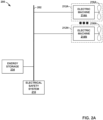
- FIG. 2A is a conceptual block diagram illustrating one example of an overvoltage protection system with adjustable threshold, in accordance with one or more aspects of the disclosure.
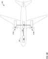
- FIG. 2B is a conceptual diagram illustrating an airframe that includes an overvoltage protection system with adjustable threshold, in accordance with one or more aspects of the disclosure.
- over voltage protection system 200 may include energy storage system 234, electrical safety system 210, electric machines 214.
- Electrical bus 202 and electrical safety system 210 may respectively be examples of electrical bus 102 and electrical safety system 110 of FIG. 1 .
- FIG. 2B is a conceptual diagram illustrating an example aircraft, in accordance with one or more aspects of the disclosure.
- Aircraft 201 of FIG. 2B may be aircraft that includes system 200, which may provide over voltage protection to aircraft 201.
- Examples of aircraft 201 include, but are not limited to fixed wing, rotorcraft, vertical takeoff (e.g., VTOL), short takeoff (e.g., STOL), and the like.
- Energy storage system (ESS) 234 may be configured to output electrical energy an electrical bus, such as electrical bus 202.
- Examples of ESS 234 include, but are not limited to, batteries, generators, and the like.
- Electrical safety system 210 may perform operations similar to electrical safety system 110 of FIG. 1 . For instance, electrical safety system 210 may protect against voltage transients on electrical bus 202 with an adjustable voltage threshold.
- System 200 may include one or more electrical propulsion modules 212A-212N (collectively, “electrical propulsion modules 212").
- Electrical propulsion modules 212 may each include an electric machine of electric machines 214A-214N (collectively, “electric machines 214") and a propulsor of propulsors 216A-216N (collectively, “propulsors 216").
- electrical propulsion modules 212 may include inverters configured to drive electric machines 214.
- electric machines 214 may operate (e.g., provide rotational mechanical energy to) propulsors 216 using electrical energy sourced from electrical bus 202.
- FIG. 3 is a flowchart illustrating example processes for controlling protection systems, in accordance with one or more techniques of this disclosure. The techniques of FIG. 3 are discussed with reference to system 100 of FIG. 1 , however other systems may perform the techniques of FIG. 3 .
- Controller 108 of system 100 may determine desired voltage suppression level for an electrical bus of an aircraft (402). For instance, controller 108 may determine, based on an altitude of aircraft 201, the desired voltage suppression level. In some examples, the desired voltage suppression level may be negatively correlated with the altitude. For instance, as the altitude increases, the desired voltage suppression level may decrease (e.g., due to effects of Paschen's law).
- Controller 108 may control a plurality of transient voltage suppressors (TVSS) 104 connected in series across the electrical bus 102 to provide the desired voltage suppression level (404). For instance, controller 108 may determine length of the chain of TVSs 104 that provide the desired voltage suppression level. As one example, where the desired voltage suppression level is 1500 volts and the breakdown voltages of TVSs 104A-104C are each 500 volts, controller 108 may cause switch 106C to close and switches 106A and 106B to open, thereby controlling operation of switches 106 such that TVSs 104 provide the desired voltage suppression level.
- TVSS transient voltage suppressors
- controller 108 may cause switch 106B to close and switches 106A and 106C to open, thereby controlling operation of switches 106 such that TVSs 104 provide the desired voltage suppression level.
- Example 1 A system comprising: a plurality of transient voltage suppressors (TVSs) that are connected in series across an electrical bus of an aircraft, the electrical bus having a high side and a low side; a plurality of switches, each switch of the plurality of switches configured to selectively shunt a corresponding TVS of the plurality of TVSs to the low side of the electrical bus; and a controller configured to: determine a desired voltage suppression level; and control operation of the plurality of switches such that the plurality of TVSs provides the desired voltage suppression level.
- TVSs transient voltage suppressors
- Example 2 The system of example 1, wherein each TVS of the plurality of TVSs has a same breakdown voltage level.
- Example 3 The system of example 1, wherein a first TVS of the plurality of TVSs provides a first breakdown voltage level, and wherein a second TVS of the plurality of TVSs provides a second breakdown voltage level that is less than the first breakdown voltage level.
- Example 4 The system of example 3, wherein the first TVS is electrically located, in the plurality of TVSs, closer to the high side than the second TVS.
- Example 5 The system of any of examples 1-4, wherein, to determine the desired voltage suppression level, the controller is configured to determine the desired voltage suppression level based on an altitude of the aircraft.
- Example 6 The system of example 5, wherein, to determine the desired voltage suppression level based on the altitude of the aircraft, the controller is configured to adjust the desired voltage suppression level with a negative correlation to the altitude of the aircraft.
- Example 7 The system of any of examples 1-6, wherein the electrical bus comprises a direct current (DC) electrical bus.
- DC direct current
- Example 8 An airframe comprising: an electrical bus having a high side and a low side; a plurality of transient voltage suppressors (TVSs) that are connected in series across the electrical bus; a plurality of switches, each switch of the plurality of switches configured to selectively shunt a corresponding TVS of the plurality of TVSs to the low side of the electrical bus; and a controller configured to: determine a desired voltage suppression level; and control operation of the plurality of switches such that the plurality of TVSs provides the desired voltage suppression level.
- TVSs transient voltage suppressors
- Example 9 The airframe of example 8, further comprising: a propulsor configured to propel the airframe; and an electric motor configured to operate the propulsor using electrical energy received from the electrical bus.
- Example 10 The airframe of example 8 or 9, wherein each TVS of the plurality of TVSs has a same breakdown voltage level.
- Example 11 The airframe of example 8 or 9, wherein a first TVS of the plurality of TVSs provides a first breakdown voltage level, and wherein a second TVS of the plurality of TVSs provides a second breakdown voltage level that is less than the first breakdown voltage level.
- Example 12 The airframe of example 11, wherein the first TVS is electrically located, in the plurality of TVSs, closer to the high side than the second TVS.
- Example 13 The airframe of any of examples 8-12, wherein, to determine the desired voltage suppression level, the controller is configured to determine the desired voltage suppression level based on an altitude of the airframe.
- Example 14 The airframe of example 13, wherein, to determine the desired voltage suppression level based on the airframe of the aircraft, the controller is configured to adjust the desired voltage suppression level with a negative correlation to the altitude of the airframe.
- Example 15 The airframe of any of examples 8-14, wherein the electrical bus comprises a direct current (DC) electrical bus.
- DC direct current
Landscapes
- Engineering & Computer Science (AREA)
- Aviation & Aerospace Engineering (AREA)
- Emergency Protection Circuit Devices (AREA)
Abstract
SUMMARYAn example system includes a plurality of transient voltage suppressors (TVSs) that are connected in series across an electrical bus of an aircraft, the electrical bus having a high side and a low side; a plurality of switches, each switch of the plurality of switches configured to selectively shunt a corresponding TVS of the plurality of TVSs to the low side of the electrical bus; and a controller configured to: determine a desired voltage suppression level; and control operation of the plurality of switches such that the plurality of TVSs provides the desired voltage suppression level.
Description
- This disclose relates to over voltage protection systems.
- Aircraft may include direct current (DC) buses to transport power for various components. Controlling such DC power buses for overvoltage events is a common and important challenge in power system design. With the increasing use of high power and voltage topologies in the aviation industry, over voltages may be a source of system failures. For example, a generator or motor of an aircraft may shed load, and the residual magnetic energy may increase a voltage level of the DC bus voltage to greater than a threshold voltage (e.g., a voltage level above-which damage may occur).
- In general, this disclosure describes protection system configured to dynamically adjust a voltage suppression level provided for a DC power bus. Controlling DC power buses for overvoltage events may be a challenge in power system design as over voltages may be a source of system failure or other undesirable events. The protection system may include a series of transient voltage suppressors (TVS) across an electrical bus having a high and low side of an aircraft. The protection circuitry may include a plurality of switches that may be configured to selectively shunt a corresponding TVS of the plurality of TVSs to the low side of the electrical bus. The TVS devices may come in multiple voltage ratings and enable a high degree of programmability for the DC over voltage protection. The protection system may also include a controller that may be configured to determine a desired voltage suppression level and control operation of the plurality of switches such that the plurality of TVSs provides the desired voltage suppression level.
- As one example, a system includes a plurality of transient voltage suppressors (TVSs) that are connected in series across an electrical bus of an aircraft, the electrical bus having a high side and a low side; a plurality of switches, each switch of the plurality of switches configured to selectively shunt a corresponding TVS of the plurality of TVSs to the low side of the electrical bus; and a controller configured to: determine a desired voltage suppression level; and control operation of the plurality of switches such that the plurality of TVSs provides the desired voltage suppression level.
- As another example, an airframe includes an electrical bus having a high side and a low side; a plurality of TVSs that are connected in series across the electrical bus; a plurality of switches, each switch of the plurality of switches configured to selectively shunt a corresponding TVS of the plurality of TVSs to the low side of the electrical bus; and a controller configured to: determine a desired voltage suppression level; and control operation of the plurality of switches such that the plurality of TVSs provides the desired voltage suppression level.
- The details of one or more examples of the disclosure are set forth in the accompanying drawings and the description below. Other features, objects, and advantages of the disclosure will be apparent from the description and drawings, and from the claims.
-
-
FIG. 1 is a conceptual block diagram illustrating over voltage protection systems including transient voltage suppressors across an electrical bus, a controller, and a plurality of switches, in accordance with one or more techniques of this disclosure. -
FIG. 2A is a conceptual block diagrams illustrating one example of an over voltage protection system configured to control switches, in accordance with one or more techniques of the disclosure. -
FIG. 2B is a conceptual diagram illustrating an example aircraft, in accordance with one or more aspects of the disclosure. -
FIG. 3 is a flowchart illustrating example processes for controlling protection systems, in accordance with one or more techniques of this disclosure. -
FIG.1 is a conceptual block diagram illustrating overvoltage protection systems 100 including electrical bus 102,electrical safety system 110 that includes transient voltage suppressors (TVSs) 104A-104D (collectively, "TVSs 104"),switches 106A-106C (collectively, "switches 106"), and acontroller 108. In some examples,system 100 may contain additional components relative to those shown inFIG. 1 or may omit some components shown inFIG. 1 . As one example,system 100 may include a multiplexer betweencontroller 108 and switches 106. - Electrical bus 102 is a plurality of conductors that are configured to provide electrical power to various components of
System 100. As shown inFIG. 1 , electrical bus includeshigh side 102A andlow side 102B. In general,high side 102A has a higher potential thanlow side 102B. Electrical bus 102 provides electrical power interconnection between various components ofsystem 100. Electrical bus 102 may include direct current (DC) bus. As one example, electrical bus 102 may include a DC bus configured to transport electrical power throughoutsystem 100. As one example, electrical bus 102 may transport electrical energy to electric motors that propel a vehicle that includessystem 100. Electrical bus 102 may receive electrical energy from one or more sources of a vehicle that includessystem 100. For instance, electrical bus 102 may receive electrical energy from as a battery, a generator or alternator. - As discussed above, in some examples, it may be desirable to suppress transient voltages on electrical bus 102. For instance, to avoid or mitigate damage to components connected to electrical bus 102, it may be desirable to suppress transient voltages on electrical bus 102. As such, in some examples,
system 100 may includeelectrical safety system 110, which may be configured to suppresses transient voltages on electrical bus 102. -
Electrical safety system 110 may perform one or more functions to provide for safe operation of electrical bus 102. As one example,electrical safety system 110 may suppress transient voltage spikes on electrical bus 102. For instance,electrical safety system 110 may include a transient voltage suppressor (TVS) that prevents or mitigates voltage spikes above a threshold voltage on electrical bus 102. However, in some examples, it may be desirable the threshold voltage level to be adjustable (e.g., during operation). - In accordance with one or more aspects of this disclosure,
electrical safety system 110 may the plurality of TVSs 104, switches 106, andcontroller 108, which may collectively enable suppression of transient voltages on electrical bus 102 with a programmable/adjustable threshold voltage level. Each of TVSs 104 may be a component configured to suppress over-voltage conditions. When a voltage across a particular TVS of TVSs 104 exceeds a threshold voltage of the particular TVS, the particular TVS may allow current to flow through the particular TVS, thereby reducing the voltage across the particular TVS. For instance, TVSs 104 may operate by shunting excess current when the induced voltage exceeds the avalanche breakdown potential. TVSs 104 may be clamping devices. As shown inFIG. 1 , TVSs 104 may be connected in series across electrical bus 102. For instance, TVSs 104 may include a series chain of TVSs connected acrosshigh side 102A andlow side 102B of electrical bus 102.Electrical safety system 110 may includenodes 105A-105C (collectively, "nodes 105") interspersed between TVSs 104. - In some examples, TVSs 104 may all have a same breakdown voltage. For instance, TVS 104Amay have a first breakdown voltage Vbreak_104A and
TVS 104B may have a second breakdown voltage Vbreak_104B, where Vbreak_104A is equal to Vbreak_104B). In other examples, some of TVSs 104 may have different breakdown voltages. For instance, TVS 104Amay have a first breakdown voltage Vbreak_104A andTVS 104B may have a second breakdown voltage Vbreak_104B, where Vbreak_104A is not equal to Vbreak_104B). In some examples, such as where some of TVSs 104 may have different breakdown voltages, the ordering of TVSs 104 may be selected such that TVSs of TVSs 104 with higher breakdown voltage levels are located at a particular position within the series chain. For instance, TVSs 104 may be ordered in descending breakdown voltage order fromhigh side 102A tolow side 102B. As one example, where a first TVS of TVSs 104 has a first breakdown voltage level and a second TVS of TVSs 104 has a second breakdown voltage level that is less than the first breakdown voltage level, the first TVS may be electrically located closer tohigh side 102A than the second TVS (e.g., the first TVS may be TVS 104A and the second TVS may beTVS 104B). While illustrated as including four TVSs, it is understood that TVSs 104 may include any number of TVSs greater than one (i.e., TVSs 104 may include at least two TVSs). - Switches 106 may selectively enable current flow based on one or more control signals. For instance, based on a control signal (e.g., received from controller 108),
switch 106A may selectively enable or disable a flow of current throughswitch 106A. Switches 106 may be electrically positioned to shunt nodes 105 to a low potential, such aslow side 102B. As one example,switch 106A may be configured to selectively shunt node 105Atolow side 102B. As another example, switch 106B may be configured to selectively shuntnode 105B tolow side 102B. As another example, switch 106C may be configured to selectively shuntnode 105C tolow side 102B. Examples of switches 106 include, but are not limited to, semiconductor switches (e.g., transistors), relays, and the like. - In general,
controller 108 may control the operation of one or more components ofsystem 100. For instance,controller 108 may control the operation of electrical bus 102, TVSs 104, switches 106, andelectrical safety system 110. In some examples,controller 108 may include a single controller that controls all of the components. In other examples,controller 108 may include multiple controllers that each control one or more components. Wherecontroller 108 includes multiple controllers, the controllers may be arranged in any configuration. -
Controller 108 may comprise any suitable arrangement of hardware, software, firmware, or any combination thereof, to perform the techniques attributed tocontroller 108 herein. Examples ofcontroller 108 include any one or more microprocessors, digital signal processors (DSPs), application specific integrated circuits (ASICs), field programmable gate arrays (FPGAs), or any other equivalent integrated or discrete logic circuitry, as well as any combinations of such components. Whencontroller 108 includes software or firmware, controller 18 further includes any necessary hardware for storing and executing the software or firmware, such as one or more processors or processing units. - In operation,
controller 108 may adjust the effective voltage suppression threshold ofelectrical safety system 110 by controlling switches 106. For instance,controller 108 may selectively open and close switches 106 to cause the effective voltage suppression threshold provided by electrical safety system 110 (e.g., the voltage threshold at which transients may be suppressed). As one example, to cause the effective voltage suppression threshold to be the breakdown voltage of just TVS 104A (i.e., Vbreak_104A),controller 108 may causeswitches node 105A tolow side 102B and bypassingTVSs 104B-104D). As another example, to cause the effective voltage suppression threshold to be the combined breakdown voltages ofTVS 104Aand TVS 104B (i.e., Vbreak_104A+Vbreak_104B),controller 108 may causeswitches node 105B tolow side 102B and bypassingTVSs controller 108 may causeswitches node 105C tolow side 102B and bypassingTVS 104D). As another example, to cause the effective voltage suppression threshold to be the combined breakdown voltages of TVS 104A-140D (i.e., Vbreak_104A+Vbreak_104B+Vbreak_104C+Vbreak_1040),controller 108 may causeswitches 106A-106C to open. In this way,electrical safety system 110 may provide dynamic and programmable control of the provided voltage suppression threshold. -
FIG. 2A is a conceptual block diagram illustrating one example of an overvoltage protection system with adjustable threshold, in accordance with one or more aspects of the disclosure.FIG. 2B is a conceptual diagram illustrating an airframe that includes an overvoltage protection system with adjustable threshold, in accordance with one or more aspects of the disclosure. As shown isFIG. 2A , overvoltage protection system 200 may includeenergy storage system 234,electrical safety system 210, electric machines 214.Electrical bus 202 andelectrical safety system 210 may respectively be examples of electrical bus 102 andelectrical safety system 110 ofFIG. 1 . -
FIG. 2B is a conceptual diagram illustrating an example aircraft, in accordance with one or more aspects of the disclosure.Aircraft 201 ofFIG. 2B may be aircraft that includessystem 200, which may provide over voltage protection toaircraft 201. Examples ofaircraft 201 include, but are not limited to fixed wing, rotorcraft, vertical takeoff (e.g., VTOL), short takeoff (e.g., STOL), and the like. - Energy storage system (ESS) 234 may be configured to output electrical energy an electrical bus, such as
electrical bus 202. Examples ofESS 234 include, but are not limited to, batteries, generators, and the like. -
Electrical safety system 210 may perform operations similar toelectrical safety system 110 ofFIG. 1 . For instance,electrical safety system 210 may protect against voltage transients onelectrical bus 202 with an adjustable voltage threshold. -
System 200 may include one or moreelectrical propulsion modules 212A-212N (collectively, "electrical propulsion modules 212"). Electrical propulsion modules 212 may each include an electric machine ofelectric machines 214A-214N (collectively, "electric machines 214") and a propulsor ofpropulsors 216A-216N (collectively, "propulsors 216"). In some examples, such as whereelectrical bus 202 is a DC bus, electrical propulsion modules 212 may include inverters configured to drive electric machines 214. In operation, electric machines 214 may operate (e.g., provide rotational mechanical energy to) propulsors 216 using electrical energy sourced fromelectrical bus 202. -
FIG. 3 is a flowchart illustrating example processes for controlling protection systems, in accordance with one or more techniques of this disclosure. The techniques ofFIG. 3 are discussed with reference tosystem 100 ofFIG. 1 , however other systems may perform the techniques ofFIG. 3 . -
Controller 108 ofsystem 100 may determine desired voltage suppression level for an electrical bus of an aircraft (402). For instance,controller 108 may determine, based on an altitude ofaircraft 201, the desired voltage suppression level. In some examples, the desired voltage suppression level may be negatively correlated with the altitude. For instance, as the altitude increases, the desired voltage suppression level may decrease (e.g., due to effects of Paschen's law). -
Controller 108 may control a plurality of transient voltage suppressors (TVSS) 104 connected in series across the electrical bus 102 to provide the desired voltage suppression level (404). For instance,controller 108 may determine length of the chain of TVSs 104 that provide the desired voltage suppression level. As one example, where the desired voltage suppression level is 1500 volts and the breakdown voltages of TVSs 104A-104C are each 500 volts,controller 108 may causeswitch 106C to close and switches 106A and 106B to open, thereby controlling operation of switches 106 such that TVSs 104 provide the desired voltage suppression level. As another example, where the desired voltage suppression level is 1500 volts and the breakdown voltages of TVS 104A is 1000 volts,TVS 104B is 500 volts, andTVS 104C is 250 volts,controller 108 may causeswitch 106B to close and switches 106A and 106C to open, thereby controlling operation of switches 106 such that TVSs 104 provide the desired voltage suppression level. - Aspects of this disclosure may also be described in the following examples.
- Example 1. A system comprising: a plurality of transient voltage suppressors (TVSs) that are connected in series across an electrical bus of an aircraft, the electrical bus having a high side and a low side; a plurality of switches, each switch of the plurality of switches configured to selectively shunt a corresponding TVS of the plurality of TVSs to the low side of the electrical bus; and a controller configured to: determine a desired voltage suppression level; and control operation of the plurality of switches such that the plurality of TVSs provides the desired voltage suppression level.
- Example 2. The system of example 1, wherein each TVS of the plurality of TVSs has a same breakdown voltage level.
- Example 3. The system of example 1, wherein a first TVS of the plurality of TVSs provides a first breakdown voltage level, and wherein a second TVS of the plurality of TVSs provides a second breakdown voltage level that is less than the first breakdown voltage level.
- Example 4. The system of example 3, wherein the first TVS is electrically located, in the plurality of TVSs, closer to the high side than the second TVS.
- Example 5. The system of any of examples 1-4, wherein, to determine the desired voltage suppression level, the controller is configured to determine the desired voltage suppression level based on an altitude of the aircraft.
- Example 6. The system of example 5, wherein, to determine the desired voltage suppression level based on the altitude of the aircraft, the controller is configured to adjust the desired voltage suppression level with a negative correlation to the altitude of the aircraft.
- Example 7. The system of any of examples 1-6, wherein the electrical bus comprises a direct current (DC) electrical bus.
- Example 8. An airframe comprising: an electrical bus having a high side and a low side; a plurality of transient voltage suppressors (TVSs) that are connected in series across the electrical bus; a plurality of switches, each switch of the plurality of switches configured to selectively shunt a corresponding TVS of the plurality of TVSs to the low side of the electrical bus; and a controller configured to: determine a desired voltage suppression level; and control operation of the plurality of switches such that the plurality of TVSs provides the desired voltage suppression level.
- Example 9. The airframe of example 8, further comprising: a propulsor configured to propel the airframe; and an electric motor configured to operate the propulsor using electrical energy received from the electrical bus.
- Example 10. The airframe of example 8 or 9, wherein each TVS of the plurality of TVSs has a same breakdown voltage level.
- Example 11. The airframe of example 8 or 9, wherein a first TVS of the plurality of TVSs provides a first breakdown voltage level, and wherein a second TVS of the plurality of TVSs provides a second breakdown voltage level that is less than the first breakdown voltage level.
- Example 12. The airframe of example 11, wherein the first TVS is electrically located, in the plurality of TVSs, closer to the high side than the second TVS.
- Example 13. The airframe of any of examples 8-12, wherein, to determine the desired voltage suppression level, the controller is configured to determine the desired voltage suppression level based on an altitude of the airframe.
- Example 14. The airframe of example 13, wherein, to determine the desired voltage suppression level based on the airframe of the aircraft, the controller is configured to adjust the desired voltage suppression level with a negative correlation to the altitude of the airframe.
- Example 15. The airframe of any of examples 8-14, wherein the electrical bus comprises a direct current (DC) electrical bus.
- Various examples of the disclosure have been described. These and other examples are within the scope of the following claims.
Claims (15)
- A system comprising:a plurality of transient voltage suppressors (TVSs) that are connected in series across an electrical bus of an aircraft, the electrical bus having a high side and a low side;a plurality of switches, each switch of the plurality of switches configured to selectively shunt a corresponding TVS of the plurality of TVSs to the low side of the electrical bus; anda controller configured to:determine a desired voltage suppression level; andcontrol operation of the plurality of switches such that the plurality of TVSs provides the desired voltage suppression level.
- The system of claim 1, wherein each TVS of the plurality of TVSs has a same breakdown voltage level.
- The system of claim 1, wherein a first TVS of the plurality of TVSs provides a first breakdown voltage level, and wherein a second TVS of the plurality of TVSs provides a second breakdown voltage level that is less than the first breakdown voltage level.
- The system of claim 3, wherein the first TVS is electrically located, in the plurality of TVSs, closer to the high side than the second TVS.
- The system of any of claims 1-4, wherein, to determine the desired voltage suppression level, the controller is configured to determine the desired voltage suppression level based on an altitude of the aircraft.
- The system of claim 5, wherein, to determine the desired voltage suppression level based on the altitude of the aircraft, the controller is configured to adjust the desired voltage suppression level with a negative correlation to the altitude of the aircraft.
- The system of any of claims 1-6, wherein the electrical bus comprises a direct current (DC) electrical bus.
- An airframe comprising:an electrical bus having a high side and a low side;a plurality of transient voltage suppressors (TVSs) that are connected in series across the electrical bus;a plurality of switches, each switch of the plurality of switches configured to selectively shunt a corresponding TVS of the plurality of TVSs to the low side of the electrical bus; anda controller configured to:determine a desired voltage suppression level; andcontrol operation of the plurality of switches such that the plurality of TVSs provides the desired voltage suppression level.
- The airframe of claim 8, further comprising:a propulsor configured to propel the airframe; andan electric motor configured to operate the propulsor using electrical energy received from the electrical bus.
- The airframe of claim 8, wherein each TVS of the plurality of TVSs has a same breakdown voltage level.
- The airframe of claim 8, wherein a first TVS of the plurality of TVSs provides a first breakdown voltage level, and wherein a second TVS of the plurality of TVSs provides a second breakdown voltage level that is less than the first breakdown voltage level.
- The airframe of claim 11, wherein the first TVS is electrically located, in the plurality of TVSs, closer to the high side than the second TVS.
- The airframe of any of claims 8-12, wherein, to determine the desired voltage suppression level, the controller is configured to determine the desired voltage suppression level based on an altitude of the airframe.
- The airframe of claim 13, wherein, to determine the desired voltage suppression level based on the airframe of the aircraft, the controller is configured to adjust the desired voltage suppression level with a negative correlation to the altitude of the airframe.
- The airframe of any of claims 8-14, wherein the electrical bus comprises a direct current (DC) electrical bus.
Applications Claiming Priority (1)
| Application Number | Priority Date | Filing Date | Title |
|---|---|---|---|
| US18/358,540 US12567737B2 (en) | 2023-07-25 | 2023-07-25 | Programmable DC power bus over voltage protection |
Publications (1)
| Publication Number | Publication Date |
|---|---|
| EP4498549A1 true EP4498549A1 (en) | 2025-01-29 |
Family
ID=88505129
Family Applications (1)
| Application Number | Title | Priority Date | Filing Date |
|---|---|---|---|
| EP23204603.7A Pending EP4498549A1 (en) | 2023-07-25 | 2023-10-19 | Programmable dc power bus over voltage protection |
Country Status (2)
| Country | Link |
|---|---|
| US (1) | US12567737B2 (en) |
| EP (1) | EP4498549A1 (en) |
Citations (5)
| Publication number | Priority date | Publication date | Assignee | Title |
|---|---|---|---|---|
| CH452666A (en) * | 1965-07-16 | 1968-03-15 | Siemens Ag | Circuit for limiting high DC voltages |
| EP2523296A1 (en) * | 2011-05-11 | 2012-11-14 | Siemens Aktiengesellschaft | Switch assembly for providing excess voltage protection and method for operating same |
| US20180331534A1 (en) * | 2017-05-15 | 2018-11-15 | Eaton Corporation | Apparatus and methods for overvoltage protection of electronic devices |
| EP3915880A1 (en) * | 2020-05-29 | 2021-12-01 | Rolls-Royce plc | Aircraft electrical power distribution |
| US20220363402A1 (en) * | 2021-05-14 | 2022-11-17 | Rolls-Royce Corporation | Voltage controlled aircraft electric propulsion system |
Family Cites Families (18)
| Publication number | Priority date | Publication date | Assignee | Title |
|---|---|---|---|---|
| WO2008124587A1 (en) | 2007-04-05 | 2008-10-16 | Georgia Tech Research Corporation | Voltage surge and overvoltage protection |
| US9537307B2 (en) | 2011-07-19 | 2017-01-03 | Hamilton Sundstrand Corporation | Overvoltage protection method and device |
| CN203056572U (en) | 2012-12-30 | 2013-07-10 | 四川九洲电器集团有限责任公司 | A surge voltage suppressing circuit |
| JP6222581B2 (en) | 2013-04-03 | 2017-11-01 | パナソニックIpマネジメント株式会社 | Battery system |
| US9711960B2 (en) | 2015-04-29 | 2017-07-18 | Hamilton Sundstrand Corporation | Built-in test circuits for transient voltage protection devices |
| US9960637B2 (en) | 2015-07-04 | 2018-05-01 | Sunverge Energy, Inc. | Renewable energy integrated storage and generation systems, apparatus, and methods with cloud distributed energy management services |
| JP6441188B2 (en) | 2015-09-01 | 2018-12-19 | 日立オートモティブシステムズ株式会社 | Battery management device, battery system, and hybrid vehicle control system |
| US10283968B2 (en) | 2015-10-08 | 2019-05-07 | Con Edison Battery Storage, Llc | Power control system with power setpoint adjustment based on POI power limits |
| US10250033B2 (en) | 2015-12-01 | 2019-04-02 | Hamilton Sundstrand Corporation | Transient voltage suppressor having built-in-test capability for solid state power controllers |
| CA3097684C (en) | 2017-04-18 | 2023-02-28 | Pascal Chretien | Electric drive train and method for feeding an electric drive train |
| US10594133B2 (en) | 2017-06-26 | 2020-03-17 | Hamilton Sundstrand Corporation | Communication bus overvoltage protection |
| US10759546B2 (en) * | 2017-08-23 | 2020-09-01 | Hamilton Sundstrand Corporation | Transient voltage suppression protection circuit including built in testing and enable-disable functionality |
| EP3512061B1 (en) | 2018-01-10 | 2020-07-22 | AIRBUS HELICOPTERS DEUTSCHLAND GmbH | An override control circuit for the reliable and safe operation of an electrical system |
| FR3090576B1 (en) | 2018-12-20 | 2021-09-10 | Airbus Helicopters | Assistance method for single-engine rotary-wing aircraft during engine failure. |
| US11209475B2 (en) * | 2019-08-06 | 2021-12-28 | Hamilton Sundstrand Corporation | Transient voltage suppressor bit stimulation |
| US11437665B2 (en) | 2020-06-29 | 2022-09-06 | Rocky Research | Battery thermal and power control system |
| US12227166B2 (en) | 2020-07-17 | 2025-02-18 | Rolls-Royce Corporation | Hybrid propulsion system power management |
| US11866162B2 (en) | 2020-12-01 | 2024-01-09 | Textron Innovations Inc. | Power management systems for electrically distributed yaw control systems |
-
2023
- 2023-07-25 US US18/358,540 patent/US12567737B2/en active Active
- 2023-10-19 EP EP23204603.7A patent/EP4498549A1/en active Pending
Patent Citations (5)
| Publication number | Priority date | Publication date | Assignee | Title |
|---|---|---|---|---|
| CH452666A (en) * | 1965-07-16 | 1968-03-15 | Siemens Ag | Circuit for limiting high DC voltages |
| EP2523296A1 (en) * | 2011-05-11 | 2012-11-14 | Siemens Aktiengesellschaft | Switch assembly for providing excess voltage protection and method for operating same |
| US20180331534A1 (en) * | 2017-05-15 | 2018-11-15 | Eaton Corporation | Apparatus and methods for overvoltage protection of electronic devices |
| EP3915880A1 (en) * | 2020-05-29 | 2021-12-01 | Rolls-Royce plc | Aircraft electrical power distribution |
| US20220363402A1 (en) * | 2021-05-14 | 2022-11-17 | Rolls-Royce Corporation | Voltage controlled aircraft electric propulsion system |
Also Published As
| Publication number | Publication date |
|---|---|
| US20250038523A1 (en) | 2025-01-30 |
| US12567737B2 (en) | 2026-03-03 |
Similar Documents
| Publication | Publication Date | Title |
|---|---|---|
| US20220190591A1 (en) | Power converter protection circuit | |
| Maqsood et al. | Integration of Z-source breakers into zonal DC ship power system microgrids | |
| US10250033B2 (en) | Transient voltage suppressor having built-in-test capability for solid state power controllers | |
| EP3051646B1 (en) | Direct current power system | |
| KR102728883B1 (en) | An electric power system | |
| EP3772817B1 (en) | Solid state phase isolation of multi-phase motors | |
| US11056967B2 (en) | Electrical supply system for an aircraft with a legacy AC network and a bipolar DC network | |
| US10608427B2 (en) | DC power system segregated into different protection zones | |
| CA2917611C (en) | Direct current power system | |
| EP3176895B1 (en) | Shared transient voltage suppressor having built-in-test capability for solid state power controllers | |
| EP3744559A1 (en) | Method for controlling auxiliary power supply system of high-speed motor train unit, system and high-speed motor train unit | |
| GB2559730B (en) | Power delivery system for multiple loads | |
| US12567737B2 (en) | Programmable DC power bus over voltage protection | |
| US20250030234A1 (en) | Power protection system | |
| CN114614688A (en) | Protection device for inverter, inverter system, and electric vehicle | |
| EP4633992A1 (en) | Protection system and protection method for power converters | |
| Gudex et al. | Multiple line-to-ground fault characterization and mitigation in mvdc shipboard electrical systems | |
| US11807377B2 (en) | Aircraft propulsion system | |
| US20220393585A1 (en) | Smart power router and protection for medium voltage dc distribution | |
| US11469754B2 (en) | Active voltage balancing for power modulation device | |
| US20260121397A1 (en) | Power supply system, moving object, and control method of power supply system | |
| US20250392117A1 (en) | Aircraft electrical-fault protection | |
| GB2641545A (en) | DC power distribution and protection system | |
| WO2025061356A1 (en) | Dc power distribution and protection system | |
| Henriksen et al. | Variable Frequency Starting Equipment for Pumped Storage Projects |
Legal Events
| Date | Code | Title | Description |
|---|---|---|---|
| PUAI | Public reference made under article 153(3) epc to a published international application that has entered the european phase |
Free format text: ORIGINAL CODE: 0009012 |
|
| STAA | Information on the status of an ep patent application or granted ep patent |
Free format text: STATUS: REQUEST FOR EXAMINATION WAS MADE |
|
| 17P | Request for examination filed |
Effective date: 20231019 |
|
| AK | Designated contracting states |
Kind code of ref document: A1 Designated state(s): AL AT BE BG CH CY CZ DE DK EE ES FI FR GB GR HR HU IE IS IT LI LT LU LV MC ME MK MT NL NO PL PT RO RS SE SI SK SM TR |
|
| P01 | Opt-out of the competence of the unified patent court (upc) registered |
Free format text: CASE NUMBER: APP_12589/2025 Effective date: 20250313 |