EP4498507A1 - Electrochemical device and electrical device - Google Patents
Electrochemical device and electrical device Download PDFInfo
- Publication number
- EP4498507A1 EP4498507A1 EP24185544.4A EP24185544A EP4498507A1 EP 4498507 A1 EP4498507 A1 EP 4498507A1 EP 24185544 A EP24185544 A EP 24185544A EP 4498507 A1 EP4498507 A1 EP 4498507A1
- Authority
- EP
- European Patent Office
- Prior art keywords
- tab group
- adapter piece
- bent
- electrode assembly
- bent section
- Prior art date
- Legal status (The legal status is an assumption and is not a legal conclusion. Google has not performed a legal analysis and makes no representation as to the accuracy of the status listed.)
- Pending
Links
- 239000000565 sealant Substances 0.000 claims description 25
- 238000009413 insulation Methods 0.000 claims description 15
- HBBGRARXTFLTSG-UHFFFAOYSA-N Lithium ion Chemical compound [Li+] HBBGRARXTFLTSG-UHFFFAOYSA-N 0.000 description 11
- 229910001416 lithium ion Inorganic materials 0.000 description 11
- 230000035882 stress Effects 0.000 description 9
- 239000002390 adhesive tape Substances 0.000 description 6
- 230000000052 comparative effect Effects 0.000 description 6
- YWXYYJSYQOXTPL-SLPGGIOYSA-N isosorbide mononitrate Chemical group [O-][N+](=O)O[C@@H]1CO[C@@H]2[C@@H](O)CO[C@@H]21 YWXYYJSYQOXTPL-SLPGGIOYSA-N 0.000 description 6
- 230000002159 abnormal effect Effects 0.000 description 4
- XAGFODPZIPBFFR-UHFFFAOYSA-N aluminium Chemical compound [Al] XAGFODPZIPBFFR-UHFFFAOYSA-N 0.000 description 4
- 229910052782 aluminium Inorganic materials 0.000 description 4
- 238000003466 welding Methods 0.000 description 4
- 238000005452 bending Methods 0.000 description 3
- 230000000694 effects Effects 0.000 description 3
- 230000006355 external stress Effects 0.000 description 3
- 238000004519 manufacturing process Methods 0.000 description 3
- 238000000034 method Methods 0.000 description 3
- 239000004698 Polyethylene Substances 0.000 description 2
- 239000004743 Polypropylene Substances 0.000 description 2
- 239000003792 electrolyte Substances 0.000 description 2
- 239000000463 material Substances 0.000 description 2
- 238000004806 packaging method and process Methods 0.000 description 2
- -1 polyethylene Polymers 0.000 description 2
- 229920000573 polyethylene Polymers 0.000 description 2
- 229920001155 polypropylene Polymers 0.000 description 2
- 238000002360 preparation method Methods 0.000 description 2
- FKNQFGJONOIPTF-UHFFFAOYSA-N Sodium cation Chemical compound [Na+] FKNQFGJONOIPTF-UHFFFAOYSA-N 0.000 description 1
- 230000009286 beneficial effect Effects 0.000 description 1
- 230000005540 biological transmission Effects 0.000 description 1
- 230000015572 biosynthetic process Effects 0.000 description 1
- 238000005520 cutting process Methods 0.000 description 1
- 230000007423 decrease Effects 0.000 description 1
- 238000007599 discharging Methods 0.000 description 1
- 238000005516 engineering process Methods 0.000 description 1
- 238000011156 evaluation Methods 0.000 description 1
- 238000007789 sealing Methods 0.000 description 1
- 239000003566 sealing material Substances 0.000 description 1
- 238000004904 shortening Methods 0.000 description 1
- 229910001415 sodium ion Inorganic materials 0.000 description 1
Images
Classifications
-
- H—ELECTRICITY
- H01—ELECTRIC ELEMENTS
- H01M—PROCESSES OR MEANS, e.g. BATTERIES, FOR THE DIRECT CONVERSION OF CHEMICAL ENERGY INTO ELECTRICAL ENERGY
- H01M50/00—Constructional details or processes of manufacture of the non-active parts of electrochemical cells other than fuel cells, e.g. hybrid cells
- H01M50/50—Current conducting connections for cells or batteries
- H01M50/531—Electrode connections inside a battery casing
- H01M50/54—Connection of several leads or tabs of plate-like electrode stacks, e.g. electrode pole straps or bridges
-
- H—ELECTRICITY
- H01—ELECTRIC ELEMENTS
- H01M—PROCESSES OR MEANS, e.g. BATTERIES, FOR THE DIRECT CONVERSION OF CHEMICAL ENERGY INTO ELECTRICAL ENERGY
- H01M50/00—Constructional details or processes of manufacture of the non-active parts of electrochemical cells other than fuel cells, e.g. hybrid cells
- H01M50/10—Primary casings; Jackets or wrappings
- H01M50/102—Primary casings; Jackets or wrappings characterised by their shape or physical structure
- H01M50/105—Pouches or flexible bags
-
- H—ELECTRICITY
- H01—ELECTRIC ELEMENTS
- H01M—PROCESSES OR MEANS, e.g. BATTERIES, FOR THE DIRECT CONVERSION OF CHEMICAL ENERGY INTO ELECTRICAL ENERGY
- H01M50/00—Constructional details or processes of manufacture of the non-active parts of electrochemical cells other than fuel cells, e.g. hybrid cells
- H01M50/10—Primary casings; Jackets or wrappings
- H01M50/172—Arrangements of electric connectors penetrating the casing
- H01M50/174—Arrangements of electric connectors penetrating the casing adapted for the shape of the cells
- H01M50/178—Arrangements of electric connectors penetrating the casing adapted for the shape of the cells for pouch or flexible bag cells
-
- H—ELECTRICITY
- H01—ELECTRIC ELEMENTS
- H01M—PROCESSES OR MEANS, e.g. BATTERIES, FOR THE DIRECT CONVERSION OF CHEMICAL ENERGY INTO ELECTRICAL ENERGY
- H01M50/00—Constructional details or processes of manufacture of the non-active parts of electrochemical cells other than fuel cells, e.g. hybrid cells
- H01M50/10—Primary casings; Jackets or wrappings
- H01M50/183—Sealing members
- H01M50/186—Sealing members characterised by the disposition of the sealing members
-
- H—ELECTRICITY
- H01—ELECTRIC ELEMENTS
- H01M—PROCESSES OR MEANS, e.g. BATTERIES, FOR THE DIRECT CONVERSION OF CHEMICAL ENERGY INTO ELECTRICAL ENERGY
- H01M50/00—Constructional details or processes of manufacture of the non-active parts of electrochemical cells other than fuel cells, e.g. hybrid cells
- H01M50/50—Current conducting connections for cells or batteries
- H01M50/528—Fixed electrical connections, i.e. not intended for disconnection
-
- H—ELECTRICITY
- H01—ELECTRIC ELEMENTS
- H01M—PROCESSES OR MEANS, e.g. BATTERIES, FOR THE DIRECT CONVERSION OF CHEMICAL ENERGY INTO ELECTRICAL ENERGY
- H01M50/00—Constructional details or processes of manufacture of the non-active parts of electrochemical cells other than fuel cells, e.g. hybrid cells
- H01M50/50—Current conducting connections for cells or batteries
- H01M50/531—Electrode connections inside a battery casing
- H01M50/533—Electrode connections inside a battery casing characterised by the shape of the leads or tabs
-
- H—ELECTRICITY
- H01—ELECTRIC ELEMENTS
- H01M—PROCESSES OR MEANS, e.g. BATTERIES, FOR THE DIRECT CONVERSION OF CHEMICAL ENERGY INTO ELECTRICAL ENERGY
- H01M50/00—Constructional details or processes of manufacture of the non-active parts of electrochemical cells other than fuel cells, e.g. hybrid cells
- H01M50/50—Current conducting connections for cells or batteries
- H01M50/531—Electrode connections inside a battery casing
- H01M50/536—Electrode connections inside a battery casing characterised by the method of fixing the leads to the electrodes, e.g. by welding
-
- H—ELECTRICITY
- H01—ELECTRIC ELEMENTS
- H01M—PROCESSES OR MEANS, e.g. BATTERIES, FOR THE DIRECT CONVERSION OF CHEMICAL ENERGY INTO ELECTRICAL ENERGY
- H01M50/00—Constructional details or processes of manufacture of the non-active parts of electrochemical cells other than fuel cells, e.g. hybrid cells
- H01M50/50—Current conducting connections for cells or batteries
- H01M50/543—Terminals
- H01M50/547—Terminals characterised by the disposition of the terminals on the cells
- H01M50/55—Terminals characterised by the disposition of the terminals on the cells on the same side of the cell
-
- H—ELECTRICITY
- H01—ELECTRIC ELEMENTS
- H01M—PROCESSES OR MEANS, e.g. BATTERIES, FOR THE DIRECT CONVERSION OF CHEMICAL ENERGY INTO ELECTRICAL ENERGY
- H01M50/00—Constructional details or processes of manufacture of the non-active parts of electrochemical cells other than fuel cells, e.g. hybrid cells
- H01M50/50—Current conducting connections for cells or batteries
- H01M50/543—Terminals
- H01M50/552—Terminals characterised by their shape
- H01M50/553—Terminals adapted for prismatic, pouch or rectangular cells
-
- H—ELECTRICITY
- H01—ELECTRIC ELEMENTS
- H01M—PROCESSES OR MEANS, e.g. BATTERIES, FOR THE DIRECT CONVERSION OF CHEMICAL ENERGY INTO ELECTRICAL ENERGY
- H01M50/00—Constructional details or processes of manufacture of the non-active parts of electrochemical cells other than fuel cells, e.g. hybrid cells
- H01M50/50—Current conducting connections for cells or batteries
- H01M50/572—Means for preventing undesired use or discharge
- H01M50/574—Devices or arrangements for the interruption of current
- H01M50/579—Devices or arrangements for the interruption of current in response to shock
-
- H—ELECTRICITY
- H01—ELECTRIC ELEMENTS
- H01M—PROCESSES OR MEANS, e.g. BATTERIES, FOR THE DIRECT CONVERSION OF CHEMICAL ENERGY INTO ELECTRICAL ENERGY
- H01M50/00—Constructional details or processes of manufacture of the non-active parts of electrochemical cells other than fuel cells, e.g. hybrid cells
- H01M50/50—Current conducting connections for cells or batteries
- H01M50/572—Means for preventing undesired use or discharge
- H01M50/584—Means for preventing undesired use or discharge for preventing incorrect connections inside or outside the batteries
- H01M50/586—Means for preventing undesired use or discharge for preventing incorrect connections inside or outside the batteries inside the batteries, e.g. incorrect connections of electrodes
-
- H—ELECTRICITY
- H01—ELECTRIC ELEMENTS
- H01M—PROCESSES OR MEANS, e.g. BATTERIES, FOR THE DIRECT CONVERSION OF CHEMICAL ENERGY INTO ELECTRICAL ENERGY
- H01M50/00—Constructional details or processes of manufacture of the non-active parts of electrochemical cells other than fuel cells, e.g. hybrid cells
- H01M50/50—Current conducting connections for cells or batteries
- H01M50/572—Means for preventing undesired use or discharge
- H01M50/584—Means for preventing undesired use or discharge for preventing incorrect connections inside or outside the batteries
- H01M50/59—Means for preventing undesired use or discharge for preventing incorrect connections inside or outside the batteries characterised by the protection means
- H01M50/595—Tapes
-
- Y—GENERAL TAGGING OF NEW TECHNOLOGICAL DEVELOPMENTS; GENERAL TAGGING OF CROSS-SECTIONAL TECHNOLOGIES SPANNING OVER SEVERAL SECTIONS OF THE IPC; TECHNICAL SUBJECTS COVERED BY FORMER USPC CROSS-REFERENCE ART COLLECTIONS [XRACs] AND DIGESTS
- Y02—TECHNOLOGIES OR APPLICATIONS FOR MITIGATION OR ADAPTATION AGAINST CLIMATE CHANGE
- Y02E—REDUCTION OF GREENHOUSE GAS [GHG] EMISSIONS, RELATED TO ENERGY GENERATION, TRANSMISSION OR DISTRIBUTION
- Y02E60/00—Enabling technologies; Technologies with a potential or indirect contribution to GHG emissions mitigation
- Y02E60/10—Energy storage using batteries
Definitions
- a multi-tab structure can improve a fast-charge capability of the battery, shorten a transmission path of lithium ions, and also reduce an internal resistance and a charge-discharge temperature increment of the battery.
- the multi-tab structure needs to be formed by interconnection welding, and one electrode terminal needs to be led out to serve as an electrode for charging the battery from an external power source or discharging the battery to provide electrical energy outward.
- the secondary battery of a multi-tab structure because the electrode terminal directly extends out of a package after being welded to a plurality of tabs, the multi-tab structure in the package possesses a low degree of freedom for lack of a cushion structure.
- the multi-tab structure is dropped, vibrating, or tugged during production or actual use, the plurality of tabs in the package are prone to be fractured under stress or incur other problems, thereby leading to failure of safety.
- An objective of this application is to provide an electrochemical device and an electrical device to alleviate the problem that tabs in a multi-tab structure in a package are prone to break.
- the electrochemical device includes a package, an electrode assembly, and a first adapter piece.
- the electrode assembly includes a first tab group.
- the electrode assembly is accommodated in the package.
- a first end of the first tab group is electrically connected to the electrode assembly.
- a second end of the first tab group is electrically connected to a first end of the first adapter piece to form a first connecting portion.
- a second end of the first adapter piece extends out of the package.
- a part that, in the first tab group, electrically connects the electrode assembly and the first connecting portion includes at least a first bent section and a second bent section. The first bent section and the second bent section are bent in opposite directions.
- the electrode assembly includes a plurality of first electrode plates, a plurality of separators, and a plurality of second electrode plates.
- Each of the separators is disposed between one of the first electrode plates and one of the second electrode plates.
- the first tab group includes a plurality of first sub-tabs. One of the first sub-tabs is electrically connected to one of the first electrode plates. The plurality of first sub-tabs are stacked together to form a first stacked portion. The first stacked portion is bent to form the first bent section and the second bent section.
- the first tab group further includes a first connecting section and a second connecting section.
- the first bent section, the first connecting section, the second bent section, the second connecting section, and the first adapter piece are connected in sequence. Of the first bent section and the second bent section, one is bent along a first direction, and the other is bent along a second direction. The first direction is opposite to the second direction.
- a length of the first connecting section is greater than or equal to a length of the second connecting section.
- the electrochemical device further includes a first adhesive-sealant.
- the first adhesive-sealant is disposed on the first adapter piece.
- the first adhesive-sealant is configured to seal the first adapter piece and the package.
- a length L1 of the first adapter piece located between the first connecting portion and the first adhesive-sealant satisfies: 0.2 mm ⁇ L1 ⁇ 10 mm.
- the electrochemical device further includes a first insulation tape group.
- the first insulation tape group covers the first tab group and the first adapter piece that is located between the first adhesive-sealant and the first tab group.
- the first insulation tape group further covers a part of the electrode assembly, and covers a part of the first adhesive-sealant.
- the electrochemical device further includes a second adapter piece.
- the electrode assembly further includes a second tab group.
- a first end of the second tab group is electrically connected to the electrode assembly.
- a second end of the second tab group is electrically connected to a first end of the second adapter piece to form a second connecting portion.
- a second end of the second adapter piece extends out of the package.
- a part that, in the second tab group, electrically connects the electrode assembly and the second connecting portion includes at least a third bent section and a fourth bent section. The third bent section and the fourth bent section are bent in opposite directions.
- the electrode assembly includes a plurality of first electrode plates, a plurality of separators, and a plurality of second electrode plates.
- Each of the separators is disposed between one of the first electrode plates and one of the second electrode plates.
- the second tab group includes a plurality of second sub-tabs. One of the second sub-tabs is electrically connected to one of the second electrode plates.
- the plurality of second sub-tabs are stacked together to form a second stacked portion. The second stacked portion is bent to form the third bent section and the fourth bent section.
- the electrical device includes the electrochemical device disclosed above.
- the electrochemical device of this application includes a package, an electrode assembly, and a first adapter piece.
- the electrode assembly is accommodated in the package.
- the electrode assembly includes a first tab group.
- a first end of the first tab group is electrically connected to the electrode assembly.
- the first tab group is electrically connected to a first end of the first adapter piece to form a first connecting portion.
- a second end of the first adapter piece extends out of the package.
- a part that, in the first tab group, electrically connects the electrode assembly and the first connecting portion includes at least a first bent section and a second bent section. The first bent section and the second bent section are bent in opposite directions, so that the first tab group located inside the package is substantially in the shape of an "S".
- the first tab group designed into the above structure, the first tab group that includes a first bent section and a second bent section is stretchable in a specified space when the electrode assembly moves relative to the package during abnormal use such as dropping or violent impact of the electrochemical device, so that the electrode assembly keeps electrically connected to the first adapter piece.
- the first tab group can cushion and reduce the stress transmitted from the first adapter piece to the electrode assembly, so as to reduce the probability of breakage at the junction between the first tab group and the electrode assembly.
- an element referred to herein as being “fixed to” another element may be directly disposed on the other element, or may be fixed to the other element with one or more elements in between.
- An element referred to herein as “connected to” another element may be connected to the other element directly or with one or more elements in between.
- a direction or a positional relationship indicated by the terms such as “up”, “down”, “in”, “out”, “vertical”, and “horizontal” used herein is a direction or positional relationship based on the illustration in the drawings, and is merely intended for ease or brevity of describing this application, but does not indicate or imply that the indicated device or component is necessarily located in the specified direction or constructed or operated in the specified direction. Therefore, such terms are not construed as a limitation on this application.
- the terms “first” and “second” are merely used for descriptive purposes, but not construed as indicating or implying relative importance.
- the electrochemical device 1 of this application includes a package 10, an electrode assembly 20, and a first adapter piece 31.
- the electrode assembly 20 is accommodated in the package 10.
- the first adapter piece 31 is electrically connected to the electrode assembly 20. At least a part of the first adapter piece 31 extends out of the package 10 to form one of electrodes of the electrochemical device 1.
- the package 10 may be a soft packaging bag made of an aluminum laminated film, or a square aluminum shell or a cylindrical aluminum shell made of a rigid aluminum sheet.
- the electrode assembly 20 includes a first tab group 24.
- a first end of the first tab group 24 is electrically connected to the electrode assembly 20.
- a second end of the first tab group 24 is electrically connected to a first end of the first adapter piece 31 to form a first connecting portion 247.
- a second end of the first adapter piece 31 extends out of the package 10.
- the first end of the first tab group 24 is electrically connected to the electrode assembly 20, and a non-end part of the first tab group 24 is electrically connected to the first end of the first adapter piece 31.
- a part between the first end and the second end of the first tab group 24 is welded to the first end of the first adapter piece 31 to form a first connecting portion 247.
- the second end of the first tab group 24 is a free end.
- a part that, in the first tab group 24, electrically connects the electrode assembly 20 and the first connecting portion 247 includes at least a first bent section 243 and a second bent section 244.
- the first bent section 243 and the second bent section 244 are bent in opposite directions, so that the first tab group 24 located inside the package 10 is substantially in the shape of an "S".
- the first tab group 24 that includes a first bent section 243 and a second bent section 244 is stretchable in a specified space when the electrode assembly 20 moves relative to the package 10 during abnormal use such as dropping or violent impact of the electrochemical device 1, so that the electrode assembly 20 keeps electrically connected to the first adapter piece 31.
- the first tab group 24 can cushion and reduce the stress transmitted from the first adapter piece 31 to the electrode assembly 20, so as to reduce the probability of breakage at the junction between the first tab group 24 and the electrode assembly 20.
- the electrode assembly 20 includes a first electrode plate 21, a second electrode plate 22, and a separator 23.
- the separator 23 is disposed between the first electrode plate 21 and the second electrode plate 22.
- the polarity of the first electrode plate 21 is opposite to the polarity of the second electrode plate 22.
- the first electrode plate 21 is a positive electrode plate
- the second electrode plate 22 is a negative electrode plate
- the first electrode plate 21 is a negative electrode plate
- the second electrode plate 22 is a positive electrode plate.
- the separator 23 is configured to separate the first electrode plate 21 from the second electrode plate 22.
- the electrode assembly 20 may be a stacked-type electrode assembly 20 or a jelly-roll electrode assembly 20.
- the electrode assembly 20 includes a first tab group 24.
- a first end of the first tab group 24 is electrically connected to the first electrode plate 21.
- a second end of the first tab group 24 is electrically connected to the first adapter piece 31.
- a part that, in the first tab group 24, electrically connects the electrode assembly 20 and the first connecting portion 247, includes a first bent section 243 and a second bent section 244.
- the first bent section 243 and the second bent section 244 are bent in opposite directions.
- the first tab group 24 further includes a first connecting section 245 and a second connecting section 246.
- the first connecting section 245 connects the first bent section 243 and the second bent section 244.
- the second connecting section 246 connects the second bent section 244 and the first adapter piece 31.
- first connecting section 245 and the second connecting section 246 may be in a flat straight state (as shown in FIG. 2 ) or in a wavy state. This application is described by an example in which the first connecting section 245 and the second connecting section 246 are in a flat straight state.
- an extension length of the first connecting section 245 is equal to an extension length of the second connecting section 246. Setting the first connecting section 245 and the second connecting section 246 to be of the same length facilitates the processing and manufacturing of the first tab group 24. It is worth noting that the extension length is deemed to be equal between the first connecting section and the second connecting section as long as a difference between the extension length of the first connecting section 245 and the extension length of the second connecting section 246 in this application is controlled to be 1 mm or less.
- the extension length of the first connecting section 245 is greater than the extension length of the second connecting section 246.
- the deformation amount of the first adapter piece 31 is extremely small. Because the strength and rigidity of the first tab group 24 are relatively small, the first tab group is prone to deform.
- the electrochemical device 1 is subjected to an external stress, the tensile stress borne by the second connecting section 246 and the first adapter piece 31 is relatively large in the vicinity of the first connecting portion 247.
- the stress transmitted to the electrode assembly 20 from the second connecting section 244 decreases gradually.
- the length of the first connecting section 243 is greater than the length of the second connecting section 244, thereby further reducing the stress transmitted to the electrode assembly 20.
- the strength and rigidity of the second connecting section 244 may be set to be higher than those of the first connecting section 243.
- the number of first bent sections 243 and the number of second bent sections 244 are two or more, the number of first connecting sections 245 and the number of second connecting sections 246 correspond to such numbers so that the bent sections can be connected to the connecting sections alternately.
- the first bent section 243, the first connecting section 245, the second bent section 244, the second connecting section 246, the first bent section 243, the second connecting section 246, the second bent section 244, and the second connecting section 246 are connected sequentially.
- the second connecting section 246 is welded to the first adapter piece 31.
- the number of first sub-tabs 241 is equal to the number of first electrode plates 21, and one first sub-tab 241 is electrically connected to each first electrode plate 21.
- the first sub-tab 241 may be welded to the first electrode plate 21 to form an electrical connection, or, the first sub-tab 241 and the first electrode plate 21 formed in one piece by cutting.
- the number of first sub-tabs 241 is greater than the number of first electrode plates 21, and at least one first sub-tab 241 is electrically connected to each first electrode plate 21. In other words, two first sub-tabs 241 are electrically connected to one of the first electrode plates 21. The above setting can further reduce the probability that the first sub-tab 241 or the first electrode plate 21 connected to the first sub-tab breaks off and the breakage leads to failure of the first electrode plate 21.
- the flow capacity of the first adapter piece 31 needs to be greater than or equal to the flow capacity of the first tab group 24.
- the thickness of the first sub-tab 241 is much smaller than the thickness of the first adapter piece 31, and the thickness of the first stacked portion 242 formed by stacking a plurality of first sub-tabs 241 is also smaller than or equal to the thickness of the first adapter piece 31. This means that the strength and rigidity of the first adapter piece 31 are greater than the strength and rigidity of the first tab group 24.
- the first bent section 243 and the second bent section 244 can be easily formed by bending the first stacked portion 242 of the first tab group 24.
- the rigidity of the first tab group 24 is low, so that the first tab group 24 is stretchable in an ample space.
- a plurality of first sub-tabs 241 are stacked to form a first stacked portion 242.
- the first sub-tab 241a close to the first bent section 243 in FIG. 2 needs to be bent.
- the above setting provides a margin of space for the first sub-tab 241a to deform, and avoids the formation of a rigid tensile connection between the first sub-tab 241a and the first stacked portion 242.
- the second end of the first tab group 24 and the first end of the first adapter piece 31 may be electrically connected by welding, bonding, or other means of connection. This application is described by using an example in which the means of connection is welding. Referring to FIG. 1 and FIG. 2 , the second end of the first tab group 24 is welded to the first end of the first adapter piece 31 to form a first connecting portion 247.
- the electrochemical device 1 further includes a first adhesive-sealant 32.
- the first adhesive-sealant 32 is disposed on the first adapter piece 31.
- the first adhesive-sealant 32 is connected to the package 10 and the first adapter piece 31 separately.
- the first adhesive-sealant 32 is configured to seal a gap between the first adapter piece 31 and the package 10, thereby ensuring airtightness inside the package 10.
- the first adhesive-sealant 32 may be made of any sealing material available in the prior art and suitable for sealing the gap between the adapter piece and the package 10.
- the material of the first adhesive-sealant 32 is not limited herein.
- the material of the first adhesive-sealant 32 may be polyethylene (PE), polypropylene (PP), or the like.
- the length L1 of the first adapter piece 31 located between the first connecting portion 247 and the first adhesive-sealant 32 satisfies: 0.2 mm ⁇ L1 ⁇ 3 mm.
- the space occupied by the first adapter piece 31 in the package 10 can be reduced by shortening the length of the first adapter piece 31 between the first connecting portion 247 and the first adhesive-sealant 32.
- the first end of the first adapter piece 31 is closer to the electrode assembly 20 than the second end of the first tab group 24.
- the second bent section 244 is disposed on the first tab group 24, which means that a clearance exists between the first connecting section 245 and the second connecting section 246.
- the electrochemical device 1 further includes a first insulation tape group 33.
- the first insulation tape group 33 covers at least the first tab group 24 and the first adapter piece 31 that is located between the first adhesive-sealant 32 and the first tab group 24, that is, covers the first tab group 24 and the first adapter piece 31 that is located inside the package 10.
- the first insulation tape group 33 is configured to wrap the first tab group 24 and the first adapter piece 31 that is located inside the package 10, so as to insulate the first tab group and the first adapter piece from the package 10, and avoid an electrical leak caused by electrical conduction between the first tab group or the first adapter piece and the package 10.
- the first insulation tape group 33 may further cover a part of the electrode assembly 20 and a part of the first adhesive-sealant 32.
- the above settings can further enhance the insulation effect on the first tab group 24 and the first adapter piece 31 located in the package 10, increase the firmness of bonding of the first insulation tape group 33, and avoid detachment and failure of the first insulation tape group 33.
- the first insulation tape group 33 includes a first adhesive tape 331 and a second adhesive tape 332.
- the first adhesive tape 331 covers a surface of the first tab group 24 and the first adapter piece 31 on one side
- the second adhesive tape 332 covers a surface of the first tab group 24 and the first adapter piece 31 on the other side. The coverage of both the first adhesive tape 331 and the second adhesive tape 332 goes beyond the contours of the first tab group 24 and the first adapter piece.
- the electrochemical device 1 of this application further includes a second adapter piece 41.
- the second adapter piece 41 is electrically connected to the electrode assembly 20. At least a part of the second adapter piece extends out of the package 10 to form another electrode of the electrochemical device 1.
- the first adapter piece 31 is a positive electrode
- the second adapter piece 41 is a negative electrode
- the first adapter piece 31 is a negative electrode
- the second adapter piece 41 is a positive electrode.
- the electrode assembly 20 further includes a second tab group 25.
- a first end of the second tab group 25 is electrically connected to the electrode assembly 20.
- a second end of the second tab group 25 is electrically connected to a first end of the second adapter piece 41 to form a second connecting portion 257.
- a second end of the first adapter piece 31 extends out of the package 10.
- the structure of the second tab group 25 may be a tab structure designed in the prior art, and the structure of the second tab group 25 may be the same as or similar to the structure of the first tab group 24. The latter is described herein as an example.
- the first end of the second tab group 25 is electrically connected to the electrode assembly 20, and a non-end part of the second tab group 25 is electrically connected to the first end of the second adapter piece 41 to form a second connecting portion 257.
- a part between the first end and the second end of the second tab group 25 is welded to the first end of the second adapter piece 41 to form the second connecting portion 257.
- the second end of the second tab group 25 is a free end.
- a part that, in the second tab group 25, electrically connects the electrode assembly 20 and the second connecting portion 257 includes at least a third bent section 253 and a fourth bent section 254.
- the third bent section 253 and the fourth bent section 254 are bent in opposite directions, so that the second tab group 25 located inside the package 10 is substantially in the shape of an "S".
- the second tab group 25 that includes a third bent section 253 and a fourth bent section 254 is stretchable in a specified space when the electrode assembly 20 moves relative to the package 10 during abnormal use such as dropping or violent impact of the electrochemical device 1, so that the electrode assembly 20 keeps electrically connected to the second adapter piece 41.
- the second tab group 25 can cushion and reduce the stress transmitted from the second adapter piece 41 to the electrode assembly 20, so as to reduce the probability of breakage at the junction between the second tab group 25 and the electrode assembly 20.
- the second tab group 25 further includes a third connecting section 255 and a fourth connecting section 256.
- the third connecting section 255 connects the third bent section 253 and the fourth bent section 254.
- the fourth connecting section 256 connects the fourth bent section 254 and the second adapter piece 41.
- the second tab group 25 includes a plurality of second sub-tabs 251.
- the second sub-tabs 251 are electrically connected to the second electrode plate 22.
- the plurality of second sub-tabs 251 are stacked together to form a second stacked portion 252.
- the second stacked portion 252 is bent at least twice in opposite directions to form the third bent section 253 and the fourth bent section 254.
- the second stacked portion 252 is bent counterclockwise to form the third bent section 253, and then the second stacked portion 252 extends upward to form a third connecting section 255.
- the second stacked portion is bent clockwise to form a fourth bent section 254.
- the second stacked portion 252 extends downward to form a fourth connecting section 256.
- the fourth connecting section 256 is connected to the second adapter piece 41.
- the structures not described in the description about the second tab group 25 may be learned by referring to the structure of the first tab group 24 described above, details of which are omitted here.
- the structure of the second adapter piece 41 is the same as or similar to the structure of the first adapter piece 31, the structures not described in the description about the second adapter piece 41 may be learned by referring to the structure of the first adapter piece 31 described above, details of which are omitted here.
- the electrochemical device 1 of this application includes a package 10, an electrode assembly 20, and a first adapter piece 31.
- the electrode assembly 20 is accommodated in the package 10.
- the electrode assembly 20 includes a first tab group 24.
- a first end of the first tab group 24 is electrically connected to the electrode assembly 20.
- the first tab group 24 is electrically connected to a first end of the first adapter piece 31 to form a first connecting portion 247.
- a second end of the first adapter piece 31 extends out of the package 10.
- a part that, in the first tab group 24, electrically connects the electrode assembly 20 and the first connecting portion 247 includes at least a first bent section 243 and a second bent section 244.
- the first bent section 243 and the second bent section 244 are bent in opposite directions, so that the first tab group 24 located inside the package 10 is substantially in the shape of an "S".
- the first tab group 24 that includes a first bent section 243 and a second bent section 244 possesses elastic stretch properties when the electrode assembly 20 moves relative to the package 10 during abnormal use such as dropping or violent impact of the electrochemical device 1, so that the electrode assembly 20 keeps electrically connected to the first adapter piece 31.
- the first tab group 24 can cushion and reduce the stress transmitted from the first adapter piece 31 to the electrode assembly 20, so as to reduce the probability of breakage at the junction between the first tab group 24 and the electrode assembly 20.
- the electrical device includes the electrochemical device.
- the specific structure and effects of the electrochemical device may be learned by referring to the above embodiment, details of which are omitted here.
- This application improves the structures of the first tab group and the second tab group of the electrode assembly in the lithium-ion pouch battery.
- the preparation process and the structure of the packaging bag, the first electrode plate, the second electrode plate, and the separator may be the corresponding preparation process and structure available in the prior art.
- a part that, in the first tab group in the electrode assembly, electrically connects the electrode assembly and the first connecting portion includes one first bent section and one second bent section (as shown in FIG. 2 or FIG. 3 ).
- the first bent section, the first connecting section, the second bent section, and the second connecting section are connected in sequence.
- a part that, in the second tab group in the electrode assembly, electrically connects the electrode assembly and the second connecting portion includes one third bent section and one fourth bent section.
- the third bent section, the third connecting section, the fourth bent section, and the fourth connecting section are connected in sequence.
- a part that, in the first tab group in the electrode assembly, electrically connects the electrode assembly and the first connecting portion includes two first bent sections and one second bent section.
- the first bent section, the first connecting section, the second bent section, the second connecting section, and the first bent section are connected in sequence.
- the second tab group in the electrode assembly, electrically connects the electrode assembly and the second connecting portion includes two third bent sections and one fourth bent section.
- the third bent section, the third connecting section, the fourth bent section, the fourth connecting section, and the third bent section are connected in sequence.
- a part that, in the first tab group in the electrode assembly, electrically connects the electrode assembly and the first connecting portion includes two first bent sections and two second bent sections (as shown in FIG. 4 ).
- the first bent section, the first connecting section, the second bent section, the second connecting section, the first bent section, the second connecting section, and the second bent section are connected in sequence.
- a part that, in the second tab group in the electrode assembly, electrically connects the electrode assembly and the second connecting portion includes two third bent sections and two fourth bent sections.
- the third bent section, the third connecting section, the fourth bent section, the fourth connecting section, the third bent section, the fourth connecting section, and the fourth bent section are connected in sequence.
- a part that, in the first tab group in the electrode assembly, electrically connects the electrode assembly and the first connecting portion includes one first bent section (as shown in FIG. 8 ), but includes no second bent section. In other words, the first tab group is bent once and then connected to the first adapter piece.
- a part that, in the second tab group, electrically connects the electrode assembly and the second connecting portion includes one third bent section. In other words, the second tab group is bent once and then connected to the second adapter piece.
- Drop test The batteries in the above embodiments and comparative embodiments are subjected to a drop test in groups, and each group includes 20 lithium-ion pouch batteries.
- a drop test process is as follows: 1. Pre-treating a lithium-ion battery at 25 °C, leaving the battery to stand at a normal temperature for 60 minutes, and then measuring the voltage, internal resistance, and capacity. 2. Fixing the lithium-ion battery into a special-purpose jig. 3. Dropping the battery downward freely from a height of 1.8 m for 7 rounds by using a special-purpose drop tester. In each round, letting the following 6 parts of the battery hit the landing point sequentially: head, tail, right head corner, right tail corner, left head corner, left tail corner (angle: 45 ⁇ 15 degrees). 4.
- a part that, in the first tab group of the electrode assembly, electrically connects the electrode assembly and the first connecting portion is set to include at least one first bent section and one second bent section, thereby effectively reducing the probability of breakage at the junction between the first tab group and the electrode assembly, and improving the safety of the lithium-ion battery.
Landscapes
- Chemical & Material Sciences (AREA)
- Chemical Kinetics & Catalysis (AREA)
- Electrochemistry (AREA)
- General Chemical & Material Sciences (AREA)
- Connection Of Batteries Or Terminals (AREA)
Abstract
An electrochemical device (1) includes a package (10), an electrode assembly (20), and a first adapter piece (31). The electrode assembly (20) includes a first tab group (24). The first tab group (24) is electrically connected to the electrode assembly (20). The first tab group (24) is electrically connected to the first adapter piece (31) to form a first connecting portion (247). The first adapter piece (31) extends out of the package (10). A part that, in the first tab group (24), electrically connects the electrode assembly (20) and the first connecting portion (247), includes at least a first bent section (243) and a second bent section (244). The first bent section (243) and the second bent section (244) are bent in opposite directions.
Description
- This application relates to the field of battery technology, and in particular, to an electrochemical device and an electrical device.
- In lithium-ion and sodium-ion secondary batteries and other types of secondary batteries, a multi-tab structure can improve a fast-charge capability of the battery, shorten a transmission path of lithium ions, and also reduce an internal resistance and a charge-discharge temperature increment of the battery. The multi-tab structure needs to be formed by interconnection welding, and one electrode terminal needs to be led out to serve as an electrode for charging the battery from an external power source or discharging the battery to provide electrical energy outward.
- The secondary battery of a multi-tab structure, because the electrode terminal directly extends out of a package after being welded to a plurality of tabs, the multi-tab structure in the package possesses a low degree of freedom for lack of a cushion structure. When the multi-tab structure is dropped, vibrating, or tugged during production or actual use, the plurality of tabs in the package are prone to be fractured under stress or incur other problems, thereby leading to failure of safety.
- An objective of this application is to provide an electrochemical device and an electrical device to alleviate the problem that tabs in a multi-tab structure in a package are prone to break.
- One technical solution of this application is to provide an electrochemical device. The electrochemical device includes a package, an electrode assembly, and a first adapter piece. The electrode assembly includes a first tab group. The electrode assembly is accommodated in the package. A first end of the first tab group is electrically connected to the electrode assembly. A second end of the first tab group is electrically connected to a first end of the first adapter piece to form a first connecting portion. A second end of the first adapter piece extends out of the package. A part that, in the first tab group, electrically connects the electrode assembly and the first connecting portion, includes at least a first bent section and a second bent section. The first bent section and the second bent section are bent in opposite directions.
- In some embodiments, the electrode assembly includes a plurality of first electrode plates, a plurality of separators, and a plurality of second electrode plates. Each of the separators is disposed between one of the first electrode plates and one of the second electrode plates. The first tab group includes a plurality of first sub-tabs. One of the first sub-tabs is electrically connected to one of the first electrode plates. The plurality of first sub-tabs are stacked together to form a first stacked portion. The first stacked portion is bent to form the first bent section and the second bent section.
- In some embodiments, the first tab group further includes a first connecting section and a second connecting section. The first bent section, the first connecting section, the second bent section, the second connecting section, and the first adapter piece are connected in sequence. Of the first bent section and the second bent section, one is bent along a first direction, and the other is bent along a second direction. The first direction is opposite to the second direction.
- In some embodiments, a length of the first connecting section is greater than or equal to a length of the second connecting section.
- In some embodiments, the electrochemical device further includes a first adhesive-sealant. The first adhesive-sealant is disposed on the first adapter piece. The first adhesive-sealant is configured to seal the first adapter piece and the package.
- In some embodiments, a length L1 of the first adapter piece located between the first connecting portion and the first adhesive-sealant satisfies: 0.2 mm ≤ L1 ≤ 10 mm.
- In some embodiments, the electrochemical device further includes a first insulation tape group. The first insulation tape group covers the first tab group and the first adapter piece that is located between the first adhesive-sealant and the first tab group. The first insulation tape group further covers a part of the electrode assembly, and covers a part of the first adhesive-sealant.
- In some embodiments, the electrochemical device further includes a second adapter piece. The electrode assembly further includes a second tab group. A first end of the second tab group is electrically connected to the electrode assembly. A second end of the second tab group is electrically connected to a first end of the second adapter piece to form a second connecting portion. A second end of the second adapter piece extends out of the package. A part that, in the second tab group, electrically connects the electrode assembly and the second connecting portion, includes at least a third bent section and a fourth bent section. The third bent section and the fourth bent section are bent in opposite directions.
- In some embodiments, the electrode assembly includes a plurality of first electrode plates, a plurality of separators, and a plurality of second electrode plates. Each of the separators is disposed between one of the first electrode plates and one of the second electrode plates. The second tab group includes a plurality of second sub-tabs. One of the second sub-tabs is electrically connected to one of the second electrode plates. The plurality of second sub-tabs are stacked together to form a second stacked portion. The second stacked portion is bent to form the third bent section and the fourth bent section.
- Another technical solution disclosed in an embodiment of this application is to provide an electrical device. The electrical device includes the electrochemical device disclosed above.
- The electrochemical device of this application includes a package, an electrode assembly, and a first adapter piece. The electrode assembly is accommodated in the package. The electrode assembly includes a first tab group. A first end of the first tab group is electrically connected to the electrode assembly. The first tab group is electrically connected to a first end of the first adapter piece to form a first connecting portion. A second end of the first adapter piece extends out of the package. A part that, in the first tab group, electrically connects the electrode assembly and the first connecting portion, includes at least a first bent section and a second bent section. The first bent section and the second bent section are bent in opposite directions, so that the first tab group located inside the package is substantially in the shape of an "S".
- With the first tab group designed into the above structure, the first tab group that includes a first bent section and a second bent section is stretchable in a specified space when the electrode assembly moves relative to the package during abnormal use such as dropping or violent impact of the electrochemical device, so that the electrode assembly keeps electrically connected to the first adapter piece. The first tab group can cushion and reduce the stress transmitted from the first adapter piece to the electrode assembly, so as to reduce the probability of breakage at the junction between the first tab group and the electrode assembly.
- To describe the technical solutions of this application more clearly, the following outlines the drawings to be used in some embodiments of this application. In all the drawings, similar elements or parts are generally identified by similar reference numerals. The elements or parts in the drawings are not necessarily drawn to scale.
-
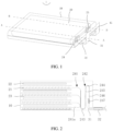
FIG. 1 is a perspective view of an electrochemical device according to an embodiment of this application; -
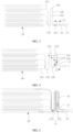
FIG. 2 is a cross-sectional view of an electrochemical device sectioned along an A-A line shown inFIG. 1 according to an embodiment of this application; -
FIG. 3 is a cross-sectional view of an electrochemical device sectioned along an A-A line shown inFIG. 1 with an unbent first adapter piece according to an embodiment of this application; -
FIG. 4 is a cross-sectional view of an electrochemical device sectioned along an A-A line shown inFIG. 1 according to another embodiment of this application; -
FIG. 5 is a cross-sectional view of an electrochemical device containing a first insulation tape group and sectioned along an A-A line shown inFIG. 1 according to another embodiment of this application; -
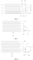
FIG. 6 is a cross-sectional view of an electrochemical device sectioned along a B-B line shown inFIG. 1 according to an embodiment of this application; -
FIG. 7 is a cross-sectional view of an electrochemical device containing no bent section and sectioned along an A-A line shown inFIG. 1 in the prior art; and -
FIG. 8 is a cross-sectional view of an electrochemical device containing merely a first bent section and sectioned along an A-A line shown inFIG. 1 in the prior art. - For ease of understanding this application, the following describes this application in more detail with reference to drawings and specific embodiments. It is hereby noted that an element referred to herein as being "fixed to" another element may be directly disposed on the other element, or may be fixed to the other element with one or more elements in between. An element referred to herein as "connected to" another element may be connected to the other element directly or with one or more elements in between. A direction or a positional relationship indicated by the terms such as "up", "down", "in", "out", "vertical", and "horizontal" used herein is a direction or positional relationship based on the illustration in the drawings, and is merely intended for ease or brevity of describing this application, but does not indicate or imply that the indicated device or component is necessarily located in the specified direction or constructed or operated in the specified direction. Therefore, such terms are not construed as a limitation on this application. In addition, the terms "first" and "second" are merely used for descriptive purposes, but not construed as indicating or implying relative importance.
- Unless otherwise defined, all technical and scientific terms used herein bear the same meanings as what is normally understood by a person skilled in the technical field of this application. The terms used in the specification of this application are merely intended to describe specific embodiments but not to limit this application. The term "and/or" used herein is intended to include any and all combinations of one or more relevant items recited.
- In addition, to the extent that no mutual conflict occurs, the technical features described below in different embodiments of this application may be combined with each other.
- Referring to
FIG. 1 , theelectrochemical device 1 of this application includes apackage 10, anelectrode assembly 20, and afirst adapter piece 31. Theelectrode assembly 20 is accommodated in thepackage 10. Thefirst adapter piece 31 is electrically connected to theelectrode assembly 20. At least a part of thefirst adapter piece 31 extends out of thepackage 10 to form one of electrodes of theelectrochemical device 1. - The
package 10 may be a soft packaging bag made of an aluminum laminated film, or a square aluminum shell or a cylindrical aluminum shell made of a rigid aluminum sheet. - As an example, still referring to
FIG. 1 , theelectrode assembly 20 includes afirst tab group 24. A first end of thefirst tab group 24 is electrically connected to theelectrode assembly 20. A second end of thefirst tab group 24 is electrically connected to a first end of thefirst adapter piece 31 to form a first connectingportion 247. A second end of thefirst adapter piece 31 extends out of thepackage 10. - In other embodiments, alternatively, the first end of the
first tab group 24 is electrically connected to theelectrode assembly 20, and a non-end part of thefirst tab group 24 is electrically connected to the first end of thefirst adapter piece 31. To be specific, a part between the first end and the second end of thefirst tab group 24 is welded to the first end of thefirst adapter piece 31 to form a first connectingportion 247. The second end of thefirst tab group 24 is a free end. - Referring to
FIG. 2 , a part that, in thefirst tab group 24, electrically connects theelectrode assembly 20 and the first connectingportion 247, includes at least a firstbent section 243 and a secondbent section 244. The firstbent section 243 and the secondbent section 244 are bent in opposite directions, so that thefirst tab group 24 located inside thepackage 10 is substantially in the shape of an "S". - With the
first tab group 24 designed into the above structure, thefirst tab group 24 that includes a firstbent section 243 and a secondbent section 244 is stretchable in a specified space when theelectrode assembly 20 moves relative to thepackage 10 during abnormal use such as dropping or violent impact of theelectrochemical device 1, so that theelectrode assembly 20 keeps electrically connected to thefirst adapter piece 31. Thefirst tab group 24 can cushion and reduce the stress transmitted from thefirst adapter piece 31 to theelectrode assembly 20, so as to reduce the probability of breakage at the junction between thefirst tab group 24 and theelectrode assembly 20. - For the
above electrode assembly 20, referring toFIG. 2 , theelectrode assembly 20 includes afirst electrode plate 21, asecond electrode plate 22, and aseparator 23. Theseparator 23 is disposed between thefirst electrode plate 21 and thesecond electrode plate 22. In some embodiments, the polarity of thefirst electrode plate 21 is opposite to the polarity of thesecond electrode plate 22. For example, when thefirst electrode plate 21 is a positive electrode plate, thesecond electrode plate 22 is a negative electrode plate; or, when thefirst electrode plate 21 is a negative electrode plate, thesecond electrode plate 22 is a positive electrode plate. When a plurality offirst electrode plates 21 and a plurality ofsecond electrode plates 22 are disposed, thefirst electrode plates 21 and thesecond electrode plates 22 are disposed alternately. Theseparator 23 is configured to separate thefirst electrode plate 21 from thesecond electrode plate 22. Theelectrode assembly 20 may be a stacked-type electrode assembly 20 or a jelly-roll electrode assembly 20. - Referring to
FIG. 1 and FIG. 2 , theelectrode assembly 20 includes afirst tab group 24. A first end of thefirst tab group 24 is electrically connected to thefirst electrode plate 21. A second end of thefirst tab group 24 is electrically connected to thefirst adapter piece 31. A part that, in thefirst tab group 24, electrically connects theelectrode assembly 20 and the first connectingportion 247, includes a firstbent section 243 and a secondbent section 244. The firstbent section 243 and the secondbent section 244 are bent in opposite directions. In some embodiments, thefirst tab group 24 further includes a first connectingsection 245 and a second connectingsection 246. The first connectingsection 245 connects the firstbent section 243 and the secondbent section 244. The second connectingsection 246 connects the secondbent section 244 and thefirst adapter piece 31. - As a result of the above structural configuration, for example, in
FIG. 2 , thefirst tab group 24 is stretchable in a space in the left-right direction. In this way, when theelectrode assembly 20 moves relatively inside thepackage 10 in the left-right direction, thefirst tab group 24 can extend or retract in the left-right direction, so that thefirst tab group 24 can maintain the electrical connection between theelectrode assembly 20 and thefirst adapter piece 31. - In some embodiments, referring to
FIG. 2 , thefirst tab group 24 includes a plurality offirst sub-tabs 241. Thefirst sub-tabs 241 are electrically connected to thefirst electrode plate 21. The plurality of first sub-tabs 241 are stacked together to form a firststacked portion 242. The firststacked portion 242 is bent at least twice in opposite directions to form the firstbent section 243 and the secondbent section 244. For example, as shown inFIG. 2 , the firststacked portion 242 is bent counterclockwise to form the firstbent section 243, and then the firststacked portion 242 extends upward to form a first connectingsection 245. Subsequently, the first stacked portion is bent clockwise to form a secondbent section 244. Afterward, the firststacked portion 242 extends downward to form a second connectingsection 246. The second connectingsection 246 is connected to thefirst adapter piece 31. - In some embodiments, the first connecting
section 245 and the second connectingsection 246 may be in a flat straight state (as shown inFIG. 2 ) or in a wavy state. This application is described by an example in which the first connectingsection 245 and the second connectingsection 246 are in a flat straight state. - In an example, referring to
FIG. 3 , an extension length of the first connectingsection 245 is equal to an extension length of the second connectingsection 246. Setting the first connectingsection 245 and the second connectingsection 246 to be of the same length facilitates the processing and manufacturing of thefirst tab group 24. It is worth noting that the extension length is deemed to be equal between the first connecting section and the second connecting section as long as a difference between the extension length of the first connectingsection 245 and the extension length of the second connectingsection 246 in this application is controlled to be 1 mm or less. - In another example, referring to
FIG. 2 andFIG. 4 , the extension length of the first connectingsection 245 is greater than the extension length of the second connectingsection 246. With the above setting, when theelectrochemical device 1 is subjected to an external stress, theelectrode assembly 20 moves relative to thepackage 10. Because the length of the first connectingsection 245 is greater, the external stress borne by thefirst tab group 24 may be reduced to provide the best protection effect. - Specifically, referring to
FIG. 2 , because the strength and rigidity of thefirst adapter piece 31 are relatively great, the deformation amount of thefirst adapter piece 31 is extremely small. Because the strength and rigidity of thefirst tab group 24 are relatively small, the first tab group is prone to deform. When theelectrochemical device 1 is subjected to an external stress, the tensile stress borne by the second connectingsection 246 and thefirst adapter piece 31 is relatively large in the vicinity of the first connectingportion 247. Under the action of the firstbent section 243 and the secondbent section 244, the stress transmitted to theelectrode assembly 20 from the second connectingsection 244 decreases gradually. The length of the first connectingsection 243 is greater than the length of the second connectingsection 244, thereby further reducing the stress transmitted to theelectrode assembly 20. - In other embodiments, because the stress borne by the second connecting
section 244 is greater than that borne by the first connectingsection 243, the strength and rigidity of the second connectingsection 244 may be set to be higher than those of the first connectingsection 243. - Referring to
FIG. 4 , when the number of firstbent sections 243 and the number of secondbent sections 244 are two or more, the number of first connectingsections 245 and the number of second connectingsections 246 correspond to such numbers so that the bent sections can be connected to the connecting sections alternately. Referring toFIG. 4 , the firstbent section 243, the first connectingsection 245, the secondbent section 244, the second connectingsection 246, the firstbent section 243, the second connectingsection 246, the secondbent section 244, and the second connectingsection 246 are connected sequentially. Finally, the second connectingsection 246 is welded to thefirst adapter piece 31. - In some embodiments, the number of
first sub-tabs 241 is equal to the number offirst electrode plates 21, and onefirst sub-tab 241 is electrically connected to eachfirst electrode plate 21. The first sub-tab 241 may be welded to thefirst electrode plate 21 to form an electrical connection, or, the first sub-tab 241 and thefirst electrode plate 21 formed in one piece by cutting. - In some other embodiments, the number of
first sub-tabs 241 is greater than the number offirst electrode plates 21, and at least onefirst sub-tab 241 is electrically connected to eachfirst electrode plate 21. In other words, twofirst sub-tabs 241 are electrically connected to one of thefirst electrode plates 21. The above setting can further reduce the probability that the first sub-tab 241 or thefirst electrode plate 21 connected to the first sub-tab breaks off and the breakage leads to failure of thefirst electrode plate 21. - Because the
first adapter piece 31 serves as a current output electrode or a current input electrode of theelectrochemical device 1, the flow capacity of thefirst adapter piece 31 needs to be greater than or equal to the flow capacity of thefirst tab group 24. Further, the thickness of the first sub-tab 241 is much smaller than the thickness of thefirst adapter piece 31, and the thickness of the firststacked portion 242 formed by stacking a plurality offirst sub-tabs 241 is also smaller than or equal to the thickness of thefirst adapter piece 31. This means that the strength and rigidity of thefirst adapter piece 31 are greater than the strength and rigidity of thefirst tab group 24. Therefore, during manufacturing and processing, the firstbent section 243 and the secondbent section 244 can be easily formed by bending the firststacked portion 242 of thefirst tab group 24. In addition, the rigidity of thefirst tab group 24 is low, so that thefirst tab group 24 is stretchable in an ample space. - In some embodiments, referring to
FIG. 2 , a plurality of first sub-tabs 241 are stacked to form a firststacked portion 242. In order to reduce the probability that the first sub-tab 241a close to the firstbent portion 243 is prone to break off from the correspondingfirst electrode plate 21 in the process of bending the firststacked portion 242 to form the firstbent section 243, the first sub-tab 241a close to the firstbent section 243 inFIG. 2 needs to be bent. The above setting provides a margin of space for the first sub-tab 241a to deform, and avoids the formation of a rigid tensile connection between the first sub-tab 241a and the firststacked portion 242. - The second end of the
first tab group 24 and the first end of thefirst adapter piece 31 may be electrically connected by welding, bonding, or other means of connection. This application is described by using an example in which the means of connection is welding. Referring toFIG. 1 and FIG. 2 , the second end of thefirst tab group 24 is welded to the first end of thefirst adapter piece 31 to form a first connectingportion 247. In an embodiment of this application, theelectrochemical device 1 further includes a first adhesive-sealant 32. The first adhesive-sealant 32 is disposed on thefirst adapter piece 31. The first adhesive-sealant 32 is connected to thepackage 10 and thefirst adapter piece 31 separately. The first adhesive-sealant 32 is configured to seal a gap between thefirst adapter piece 31 and thepackage 10, thereby ensuring airtightness inside thepackage 10. - The first adhesive-
sealant 32 may be made of any sealing material available in the prior art and suitable for sealing the gap between the adapter piece and thepackage 10. The material of the first adhesive-sealant 32 is not limited herein. For example, the material of the first adhesive-sealant 32 may be polyethylene (PE), polypropylene (PP), or the like. - In some embodiments, a length L1 of the
first adapter piece 31 located between the first connectingportion 247 and the first adhesive-sealant 32 satisfies: 0.2 mm ≤ L1 ≤ 10 mm. - Referring to
FIG. 3 , when thefirst adapter piece 31 is not bent, the length L1 of thefirst adapter piece 31 located between the first connectingportion 247 and the first adhesive-sealant 32 satisfies: 0.2 mm ≤ L1 ≤ 3 mm. When thefirst adapter piece 31 is electrically connected in a straight state to the second end of thefirst tab group 24, the space occupied by thefirst adapter piece 31 in thepackage 10 can be reduced by shortening the length of thefirst adapter piece 31 between the first connectingportion 247 and the first adhesive-sealant 32. - Referring to
FIG. 4 , when thefirst adapter piece 31 is bent, the length L1 of thefirst adapter piece 31 located between the first connectingportion 247 and the first adhesive-sealant 32 satisfies: 3 mm ≤ L1 ≤ 10 mm. When thefirst adapter piece 31 located in thepackage 10 is bent and then electrically connected to thefirst tab group 24, the length of thefirst adapter piece 31 may be increased by an appropriate amount. By bending thefirst adapter piece 31 located in thepackage 10 and then connecting the first adapter piece to thefirst tab group 24, the welding area of the first connectingportion 247 can be increased, so as to ensure firmness of the connection between thefirst adapter piece 31 and thefirst tab group 24. Thefirst adapter piece 31 is bent, so as to reduce occupation of the space inside thepackage 10. - In an embodiment in which the
first adapter piece 31 is bent and then electrically connected to thefirst tab group 24, as shown inFIG. 2 andFIG. 4 , the first end of thefirst adapter piece 31 is closer to theelectrode assembly 20 than the second end of thefirst tab group 24. The secondbent section 244 is disposed on thefirst tab group 24, which means that a clearance exists between the first connectingsection 245 and the second connectingsection 246. By placing thefirst adapter piece 31 on a side closer to theelectrode assembly 20, this application can fully utilize the clearance, and further reduce the space occupied by thefirst adapter piece 31 and thefirst tab group 24 inside thepackage 10. - Referring to
FIG. 5 , theelectrochemical device 1 further includes a firstinsulation tape group 33. The firstinsulation tape group 33 covers at least thefirst tab group 24 and thefirst adapter piece 31 that is located between the first adhesive-sealant 32 and thefirst tab group 24, that is, covers thefirst tab group 24 and thefirst adapter piece 31 that is located inside thepackage 10. The firstinsulation tape group 33 is configured to wrap thefirst tab group 24 and thefirst adapter piece 31 that is located inside thepackage 10, so as to insulate the first tab group and the first adapter piece from thepackage 10, and avoid an electrical leak caused by electrical conduction between the first tab group or the first adapter piece and thepackage 10. - The first
insulation tape group 33 may further cover a part of theelectrode assembly 20 and a part of the first adhesive-sealant 32. The above settings can further enhance the insulation effect on thefirst tab group 24 and thefirst adapter piece 31 located in thepackage 10, increase the firmness of bonding of the firstinsulation tape group 33, and avoid detachment and failure of the firstinsulation tape group 33. - In some embodiments, the first
insulation tape group 33 includes a firstadhesive tape 331 and a secondadhesive tape 332. The firstadhesive tape 331 covers a surface of thefirst tab group 24 and thefirst adapter piece 31 on one side, and the secondadhesive tape 332 covers a surface of thefirst tab group 24 and thefirst adapter piece 31 on the other side. The coverage of both the firstadhesive tape 331 and the secondadhesive tape 332 goes beyond the contours of thefirst tab group 24 and the first adapter piece. - Referring to
FIG. 1 , theelectrochemical device 1 of this application further includes asecond adapter piece 41. Thesecond adapter piece 41 is electrically connected to theelectrode assembly 20. At least a part of the second adapter piece extends out of thepackage 10 to form another electrode of theelectrochemical device 1. For example, thefirst adapter piece 31 is a positive electrode, and thesecond adapter piece 41 is a negative electrode; or, thefirst adapter piece 31 is a negative electrode, and thesecond adapter piece 41 is a positive electrode. - As an example, referring to
FIG. 6 , theelectrode assembly 20 further includes asecond tab group 25. A first end of thesecond tab group 25 is electrically connected to theelectrode assembly 20. A second end of thesecond tab group 25 is electrically connected to a first end of thesecond adapter piece 41 to form a second connectingportion 257. A second end of thefirst adapter piece 31 extends out of thepackage 10. Understandably, the structure of thesecond tab group 25 may be a tab structure designed in the prior art, and the structure of thesecond tab group 25 may be the same as or similar to the structure of thefirst tab group 24. The latter is described herein as an example. - In other embodiments, alternatively, the first end of the
second tab group 25 is electrically connected to theelectrode assembly 20, and a non-end part of thesecond tab group 25 is electrically connected to the first end of thesecond adapter piece 41 to form a second connectingportion 257. To be specific, a part between the first end and the second end of thesecond tab group 25 is welded to the first end of thesecond adapter piece 41 to form the second connectingportion 257. The second end of thesecond tab group 25 is a free end. - Referring to
FIG. 6 , a part that, in thesecond tab group 25, electrically connects theelectrode assembly 20 and the second connectingportion 257, includes at least a thirdbent section 253 and a fourthbent section 254. The thirdbent section 253 and the fourthbent section 254 are bent in opposite directions, so that thesecond tab group 25 located inside thepackage 10 is substantially in the shape of an "S". - With the
second tab group 25 designed into the above structure, thesecond tab group 25 that includes a thirdbent section 253 and a fourthbent section 254 is stretchable in a specified space when theelectrode assembly 20 moves relative to thepackage 10 during abnormal use such as dropping or violent impact of theelectrochemical device 1, so that theelectrode assembly 20 keeps electrically connected to thesecond adapter piece 41. Thesecond tab group 25 can cushion and reduce the stress transmitted from thesecond adapter piece 41 to theelectrode assembly 20, so as to reduce the probability of breakage at the junction between thesecond tab group 25 and theelectrode assembly 20. - Referring to
FIG. 6 , in some embodiments, thesecond tab group 25 further includes a third connectingsection 255 and a fourth connectingsection 256. The third connectingsection 255 connects the thirdbent section 253 and the fourthbent section 254. The fourth connectingsection 256 connects the fourthbent section 254 and thesecond adapter piece 41. - Referring to
FIG. 6 , in some embodiments, thesecond tab group 25 includes a plurality ofsecond sub-tabs 251. Thesecond sub-tabs 251 are electrically connected to thesecond electrode plate 22. The plurality of second sub-tabs 251 are stacked together to form a secondstacked portion 252. The secondstacked portion 252 is bent at least twice in opposite directions to form the thirdbent section 253 and the fourthbent section 254. For example, as shown inFIG. 3 , the secondstacked portion 252 is bent counterclockwise to form the thirdbent section 253, and then the secondstacked portion 252 extends upward to form a third connectingsection 255. Subsequently, the second stacked portion is bent clockwise to form a fourthbent section 254. Afterward, the secondstacked portion 252 extends downward to form a fourth connectingsection 256. The fourth connectingsection 256 is connected to thesecond adapter piece 41. - Because the structure of the
second tab group 25 in this embodiment of this application is the same as or similar to the structure of thefirst tab group 24, the structures not described in the description about thesecond tab group 25 may be learned by referring to the structure of thefirst tab group 24 described above, details of which are omitted here. Similarly, because the structure of thesecond adapter piece 41 is the same as or similar to the structure of thefirst adapter piece 31, the structures not described in the description about thesecond adapter piece 41 may be learned by referring to the structure of thefirst adapter piece 31 described above, details of which are omitted here. - The
electrochemical device 1 of this application includes apackage 10, anelectrode assembly 20, and afirst adapter piece 31. Theelectrode assembly 20 is accommodated in thepackage 10. Theelectrode assembly 20 includes afirst tab group 24. A first end of thefirst tab group 24 is electrically connected to theelectrode assembly 20. Thefirst tab group 24 is electrically connected to a first end of thefirst adapter piece 31 to form a first connectingportion 247. A second end of thefirst adapter piece 31 extends out of thepackage 10. A part that, in thefirst tab group 24, electrically connects theelectrode assembly 20 and the first connectingportion 247, includes at least a firstbent section 243 and a secondbent section 244. The firstbent section 243 and the secondbent section 244 are bent in opposite directions, so that thefirst tab group 24 located inside thepackage 10 is substantially in the shape of an "S". - With the
first tab group 24 designed into the above structure, thefirst tab group 24 that includes a firstbent section 243 and a secondbent section 244 possesses elastic stretch properties when theelectrode assembly 20 moves relative to thepackage 10 during abnormal use such as dropping or violent impact of theelectrochemical device 1, so that theelectrode assembly 20 keeps electrically connected to thefirst adapter piece 31. Thefirst tab group 24 can cushion and reduce the stress transmitted from thefirst adapter piece 31 to theelectrode assembly 20, so as to reduce the probability of breakage at the junction between thefirst tab group 24 and theelectrode assembly 20. - This application further provides an electrical device embodiment. The electrical device includes the electrochemical device. The specific structure and effects of the electrochemical device may be learned by referring to the above embodiment, details of which are omitted here.
- For ease of understanding the technical solutions and beneficial effects of the electrochemical device according to an embodiment of this application, the following describes a lithium-ion pouch battery as an example.
- This application improves the structures of the first tab group and the second tab group of the electrode assembly in the lithium-ion pouch battery. For the lithium-ion pouch battery, the preparation process and the structure of the packaging bag, the first electrode plate, the second electrode plate, and the separator may be the corresponding preparation process and structure available in the prior art.
- A part that, in the first tab group in the electrode assembly, electrically connects the electrode assembly and the first connecting portion, includes one first bent section and one second bent section (as shown in
FIG. 2 orFIG. 3 ). In other words, the first bent section, the first connecting section, the second bent section, and the second connecting section are connected in sequence. A part that, in the second tab group in the electrode assembly, electrically connects the electrode assembly and the second connecting portion, includes one third bent section and one fourth bent section. In other words, the third bent section, the third connecting section, the fourth bent section, and the fourth connecting section are connected in sequence. - A part that, in the first tab group in the electrode assembly, electrically connects the electrode assembly and the first connecting portion, includes two first bent sections and one second bent section. In other words, the first bent section, the first connecting section, the second bent section, the second connecting section, and the first bent section are connected in sequence. Apart that, in the second tab group in the electrode assembly, electrically connects the electrode assembly and the second connecting portion, includes two third bent sections and one fourth bent section. In other words, the third bent section, the third connecting section, the fourth bent section, the fourth connecting section, and the third bent section are connected in sequence.
- A part that, in the first tab group in the electrode assembly, electrically connects the electrode assembly and the first connecting portion, includes two first bent sections and two second bent sections (as shown in
FIG. 4 ). In other words, the first bent section, the first connecting section, the second bent section, the second connecting section, the first bent section, the second connecting section, and the second bent section are connected in sequence. A part that, in the second tab group in the electrode assembly, electrically connects the electrode assembly and the second connecting portion, includes two third bent sections and two fourth bent sections. In other words, the third bent section, the third connecting section, the fourth bent section, the fourth connecting section, the third bent section, the fourth connecting section, and the fourth bent section are connected in sequence. - A part that, in the first tab group in the electrode assembly, electrically connects the electrode assembly and the first connecting portion, includes no bent section (as shown in
FIG. 7 ). In other words, the first tab group is directly connected to the first adapter piece. A part that, in the second tab group, electrically connects the electrode assembly and the second connecting portion, includes no bent section. In other words, the second tab group is directly connected to the second adapter piece. - A part that, in the first tab group in the electrode assembly, electrically connects the electrode assembly and the first connecting portion, includes one first bent section (as shown in
FIG. 8 ), but includes no second bent section. In other words, the first tab group is bent once and then connected to the first adapter piece. A part that, in the second tab group, electrically connects the electrode assembly and the second connecting portion, includes one third bent section. In other words, the second tab group is bent once and then connected to the second adapter piece. - Drop test: The batteries in the above embodiments and comparative embodiments are subjected to a drop test in groups, and each group includes 20 lithium-ion pouch batteries.
- A drop test process is as follows:
1. Pre-treating a lithium-ion battery at 25 °C, leaving the battery to stand at a normal temperature for 60 minutes, and then measuring the voltage, internal resistance, and capacity.
2. Fixing the lithium-ion battery into a special-purpose jig.
3. Dropping the battery downward freely from a height of 1.8 m for 7 rounds by using a special-purpose drop tester. In each round, letting the following 6 parts of the battery hit the landing point sequentially: head, tail, right head corner, right tail corner, left head corner, left tail corner (angle: 45±15 degrees).
4. Checking the battery status after completion of each round of test, and stopping the drop test if the lithium-ion battery leaks electrolyte, heats up, smokes, catches fire, or incurs a voltage drop of 50 mV or more. Leaving the lithium-ion battery to stand at a normal temperature for 24 hours after completion of the drop test, and then measuring the voltage and internal resistance of the battery.
5. Evaluation criteria: The test is passed if no fire or electrolyte leak occurs and the voltage drop is less than 50 mV. The test results are recorded in Table 1 below.Table 1 Embodiment Number of failed specimens/total number of specimens Comparative Embodiment 120/20 Comparative Embodiment 2 18/20 Embodiment 10/20 Embodiment 2 0/20 Embodiment 3 0/20 - Conclusion: As can be seen from
Comparative Embodiments 1 and 2 andEmbodiments 1 to 3, a part that, in the first tab group of the electrode assembly, electrically connects the electrode assembly and the first connecting portion, is set to include at least one first bent section and one second bent section, thereby effectively reducing the probability of breakage at the junction between the first tab group and the electrode assembly, and improving the safety of the lithium-ion battery. - What is described above is merely some embodiments of this application, and does not limit the patent scope of this application in any way. All equivalent structural variations and equivalent process variations made by using the content of the specification and the drawings of this application, and the content hereof used directly or indirectly in other related technical fields, still fall within the patent protection scope of this application.
Claims (10)
- An electrochemical device (1), comprising a package (10), an electrode assembly (20), and a first adapter piece (31); wherein the electrode assembly (20) comprises a first tab group (24); the electrode assembly (20) is accommodated in the package (10); a first end of the first tab group (24) is electrically connected to the electrode assembly (20); a second end of the first tab group (24) is electrically connected to a first end of the first adapter piece (31) to form a first connecting portion (247); and a second end of the first adapter piece (31) extends out of the package (10); characterized in that,a part of the first tab group (24) electrically connects the electrode assembly (20) and the first connecting portion (247), the part of the first tab group (24) comprises a first bent section (243) and a second bent section (244); andthe first bent section (243) and the second bent section (244) are bent in opposite directions.
- The electrochemical device (1) according to claim 1, characterized in that,the electrode assembly (20) comprises a plurality of first electrode plates (21), a plurality of separators (23), and a plurality of second electrode plates (22);each of the separators (23) is provided between one of the first electrode plates (21) and one of the second electrode plates (22);the first tab group (24) comprises a plurality of first sub-tabs (241);one of the first sub-tabs (241) is electrically connected to one of the first electrode plates (21);the plurality of first sub-tabs (241) are stacked together to form a first stacked portion (242); andthe first stacked portion (242) is bent to form the first bent section (243) and the second bent section (244).
- The electrochemical device (1) according to claim 2, characterized in that,the first tab group (24) further comprises a first connecting section (245) and a second connecting section (246);the first bent section (243), the first connecting section (245), the second bent section (244), the second connecting section (246), and the first adapter piece (31) are connected in sequence;of the first bent section (243) and the second bent section (244), one is bent along a first direction, and the other is bent along a second direction, andthe first direction is opposite to the second direction.
- The electrochemical device (1) according to claim 3, characterized in that,
a length of the first connecting section (245) is greater than or equal to a length of the second connecting section (246). - The electrochemical device (1) according to any one of claims 1 to 4, characterized in that,the electrochemical device (1) further comprises a first adhesive-sealant (32);the first adhesive-sealant (32) is provided on the first adapter piece (31); andthe first adhesive-sealant (32) seals the first adapter piece (31) and the package (10).
- The electrochemical device (1) according to claim 5, characterized in that,
a length L1 of the first adapter piece (31) located between the first connecting portion (247) and the first adhesive-sealant (32) satisfies: 0.2 mm ≤ L1 ≤ 10 mm. - The electrochemical device (1) according to claim 5, characterized in that,the electrochemical device (1) further comprises a first insulation tape group (33);the first insulation tape group (33) covers the first tab group (24) and a part of the first adapter piece (31), the part of the first adapter piece (31) is located between the first adhesive-sealant (32) and the first tab group (24); andthe first insulation tape group (33) further covers a part of the electrode assembly (20) and a part of the first adhesive-sealant (32).
- The electrochemical device (1) according to any one of claims 1 to 7, characterized in that,the electrochemical device (1) further comprises a second adapter piece (41);the electrode assembly (20) further comprises a second tab group (25);a first end of the second tab group (25) is electrically connected to the electrode assembly (20);a second end of the second tab group (25) is electrically connected to a first end of the second adapter piece (41) to form a second connecting portion (257);a second end of the second adapter piece (41) extends out of the package (10);a part of the second tab group (25) electrically connects the electrode assembly (20) and the second connecting portion (257), the part of the second tab group (25) comprises a third bent section (253) and a fourth bent section (254); andthe third bent section (253) and the fourth bent section (254) are bent in opposite directions.
- The electrochemical device (1) according to claim 8, characterized in that,the second tab group (25) comprises a plurality of second sub-tabs (251);one of the second sub-tabs (251) is electrically connected to one of the second electrode plates (22);the plurality of second sub-tabs (251) are stacked together to form a second stacked portion (252); andthe second stacked portion (252) is bent to form the third bent section (253) and the fourth bent section (254).
- An electrical device, characterized in that, the electrical device comprises the electrochemical device (1) according to any one of claims 1 to 9.
Applications Claiming Priority (1)
| Application Number | Priority Date | Filing Date | Title |
|---|---|---|---|
| CN202310936246.9A CN116885399A (en) | 2023-07-27 | 2023-07-27 | Electrochemical devices and electrical equipment |
Publications (1)
| Publication Number | Publication Date |
|---|---|
| EP4498507A1 true EP4498507A1 (en) | 2025-01-29 |
Family
ID=88271413
Family Applications (1)
| Application Number | Title | Priority Date | Filing Date |
|---|---|---|---|
| EP24185544.4A Pending EP4498507A1 (en) | 2023-07-27 | 2024-06-28 | Electrochemical device and electrical device |
Country Status (3)
| Country | Link |
|---|---|
| US (1) | US20250038374A1 (en) |
| EP (1) | EP4498507A1 (en) |
| CN (1) | CN116885399A (en) |
Families Citing this family (5)
| Publication number | Priority date | Publication date | Assignee | Title |
|---|---|---|---|---|
| CN117578039A (en) * | 2023-12-11 | 2024-02-20 | 宁德新能源科技有限公司 | A kind of electric core and battery |
| CN117791053A (en) * | 2023-12-28 | 2024-03-29 | 宁德新能源科技有限公司 | Batteries and electrical equipment |
| CN117832774A (en) * | 2024-01-08 | 2024-04-05 | 宁德新能源科技有限公司 | Electrode assembly and electrochemical device |
| CN118281498A (en) * | 2024-03-30 | 2024-07-02 | 宁德新能源科技有限公司 | Battery cell and manufacturing method thereof, battery and electrical equipment |
| CN118872144A (en) * | 2024-03-30 | 2024-10-29 | 宁德新能源科技有限公司 | Secondary batteries and electronic devices |
Citations (5)
| Publication number | Priority date | Publication date | Assignee | Title |
|---|---|---|---|---|
| EP2485298A1 (en) * | 2011-02-04 | 2012-08-08 | Sanyo Electric Co., Ltd. | Stack type battery and method of manufacturing the same |
| CN113363642A (en) * | 2021-05-31 | 2021-09-07 | 宁德新能源科技有限公司 | Battery cell and power utilization device |
| CN114649559A (en) * | 2022-03-31 | 2022-06-21 | 东莞新能安科技有限公司 | Electrochemical device and electronic device |
| EP4207477A1 (en) * | 2021-06-23 | 2023-07-05 | Dongguan Poweramp Technology Limited | Electrochemical device and electronic device |
| EP4213295A1 (en) * | 2022-01-14 | 2023-07-19 | Samsung SDI Co., Ltd. | Secondary battery |
Family Cites Families (6)
| Publication number | Priority date | Publication date | Assignee | Title |
|---|---|---|---|---|
| CN112913076A (en) * | 2018-11-21 | 2021-06-04 | 深圳市大疆创新科技有限公司 | Smart battery and its lithium battery |
| CN113270671B (en) * | 2021-05-13 | 2024-04-16 | 宁德新能源科技有限公司 | Battery cells and electrical devices |
| CN114373885B (en) * | 2021-12-31 | 2023-09-15 | 东莞新能源科技有限公司 | Electrochemical device and electric equipment |
| CN218414893U (en) * | 2022-09-16 | 2023-01-31 | 宁德时代新能源科技股份有限公司 | Battery cells, batteries and electrical equipment |
| CN219123421U (en) * | 2022-11-30 | 2023-06-02 | 深圳欣旺达智能科技有限公司 | Positive electrode tab, tab structure with positive electrode tab and battery |
| CN115832450A (en) * | 2022-12-14 | 2023-03-21 | 东莞新能源科技有限公司 | Electrode assembly and electrochemical device |
-
2023
- 2023-07-27 CN CN202310936246.9A patent/CN116885399A/en active Pending
-
2024
- 2024-06-28 EP EP24185544.4A patent/EP4498507A1/en active Pending
- 2024-07-26 US US18/785,605 patent/US20250038374A1/en active Pending
Patent Citations (5)
| Publication number | Priority date | Publication date | Assignee | Title |
|---|---|---|---|---|
| EP2485298A1 (en) * | 2011-02-04 | 2012-08-08 | Sanyo Electric Co., Ltd. | Stack type battery and method of manufacturing the same |
| CN113363642A (en) * | 2021-05-31 | 2021-09-07 | 宁德新能源科技有限公司 | Battery cell and power utilization device |
| EP4207477A1 (en) * | 2021-06-23 | 2023-07-05 | Dongguan Poweramp Technology Limited | Electrochemical device and electronic device |
| EP4213295A1 (en) * | 2022-01-14 | 2023-07-19 | Samsung SDI Co., Ltd. | Secondary battery |
| CN114649559A (en) * | 2022-03-31 | 2022-06-21 | 东莞新能安科技有限公司 | Electrochemical device and electronic device |
Also Published As
| Publication number | Publication date |
|---|---|
| CN116885399A (en) | 2023-10-13 |
| US20250038374A1 (en) | 2025-01-30 |
Similar Documents
| Publication | Publication Date | Title |
|---|---|---|
| US20250038374A1 (en) | Electrochemical device and electrical device | |
| US12068506B2 (en) | Flexible battery | |
| CN101517806B (en) | Electrode assembly having stable lead-tap bonding and electrochemical cell comprising same | |
| US20120040235A1 (en) | Pouch having improved safety, pouch-type secondary battery including the same, and medium-to-large battery pack | |
| EP2680361A1 (en) | Jelly roll-type electrode assembly with active material pattern-coated thereon, and secondary battery having same | |
| KR102300870B1 (en) | An electrode assembly | |
| KR20140123007A (en) | Battery Cell Having Round Corner | |
| KR101255171B1 (en) | secondary battery and manufacturing method thereof | |
| KR101367751B1 (en) | secondary battery and manufacturing method thereof | |
| US10651457B2 (en) | Battery module | |
| KR20190024451A (en) | Flexible battery having exterior part formed pattern | |
| WO2013122448A1 (en) | Lithium-ion battery | |
| US9012064B2 (en) | Current collecting plate and secondary battery including current collecting plate | |
| CN111630699B (en) | Secondary battery | |
| US12500295B2 (en) | Exterior material, method of forming pattern on exterior material, and method of manufacturing battery including exterior material | |
| KR102522701B1 (en) | The Secondary Battery | |
| US20240387833A1 (en) | Current collector for secondary battery and cylindrical battery cell comprising the same | |
| KR101924424B1 (en) | Flexible battery assembly having bending structure of electrode lead | |
| JP5756638B2 (en) | Square battery electrode unit | |
| KR20180122073A (en) | Flexible electrode assembly having strengthening structure using expanded metal on outermost electrode | |
| KR102959636B1 (en) | Battery module with busbar frame for preventing spring back of cell lead and battery pack including the same | |
| KR20180105995A (en) | Flexible battery assembly having strengthening tab joint structure between electrode tab and electrode lead | |
| KR102908460B1 (en) | Secondary battery with a vent | |
| US20250105473A1 (en) | Battery cell, battery module including battery cell, and battery pack including battery module | |
| KR20250132189A (en) | Battery cell and battery module intcluding the same |
Legal Events
| Date | Code | Title | Description |
|---|---|---|---|
| PUAI | Public reference made under article 153(3) epc to a published international application that has entered the european phase |
Free format text: ORIGINAL CODE: 0009012 |
|
| STAA | Information on the status of an ep patent application or granted ep patent |
Free format text: STATUS: REQUEST FOR EXAMINATION WAS MADE |
|
| 17P | Request for examination filed |
Effective date: 20240628 |
|
| AK | Designated contracting states |
Kind code of ref document: A1 Designated state(s): AL AT BE BG CH CY CZ DE DK EE ES FI FR GB GR HR HU IE IS IT LI LT LU LV MC ME MK MT NL NO PL PT RO RS SE SI SK SM TR |