EP4498498A1 - Battery storage tray - Google Patents
Battery storage tray Download PDFInfo
- Publication number
- EP4498498A1 EP4498498A1 EP24191305.2A EP24191305A EP4498498A1 EP 4498498 A1 EP4498498 A1 EP 4498498A1 EP 24191305 A EP24191305 A EP 24191305A EP 4498498 A1 EP4498498 A1 EP 4498498A1
- Authority
- EP
- European Patent Office
- Prior art keywords
- battery
- insert
- battery storage
- storage tray
- inserts
- Prior art date
- Legal status (The legal status is an assumption and is not a legal conclusion. Google has not performed a legal analysis and makes no representation as to the accuracy of the status listed.)
- Pending
Links
Images








Classifications
-
- H—ELECTRICITY
- H01—ELECTRIC ELEMENTS
- H01M—PROCESSES OR MEANS, e.g. BATTERIES, FOR THE DIRECT CONVERSION OF CHEMICAL ENERGY INTO ELECTRICAL ENERGY
- H01M50/00—Constructional details or processes of manufacture of the non-active parts of electrochemical cells other than fuel cells, e.g. hybrid cells
- H01M50/20—Mountings; Secondary casings or frames; Racks, modules or packs; Suspension devices; Shock absorbers; Transport or carrying devices; Holders
- H01M50/267—Mountings; Secondary casings or frames; Racks, modules or packs; Suspension devices; Shock absorbers; Transport or carrying devices; Holders having means for adapting to batteries or cells of different types or different sizes
-
- B—PERFORMING OPERATIONS; TRANSPORTING
- B65—CONVEYING; PACKING; STORING; HANDLING THIN OR FILAMENTARY MATERIAL
- B65D—CONTAINERS FOR STORAGE OR TRANSPORT OF ARTICLES OR MATERIALS, e.g. BAGS, BARRELS, BOTTLES, BOXES, CANS, CARTONS, CRATES, DRUMS, JARS, TANKS, HOPPERS, FORWARDING CONTAINERS; ACCESSORIES, CLOSURES, OR FITTINGS THEREFOR; PACKAGING ELEMENTS; PACKAGES
- B65D88/00—Large containers
- B65D88/005—Large containers of variable capacity, e.g. with movable or adjustable walls or wall parts, modular
-
- B—PERFORMING OPERATIONS; TRANSPORTING
- B65—CONVEYING; PACKING; STORING; HANDLING THIN OR FILAMENTARY MATERIAL
- B65D—CONTAINERS FOR STORAGE OR TRANSPORT OF ARTICLES OR MATERIALS, e.g. BAGS, BARRELS, BOTTLES, BOXES, CANS, CARTONS, CRATES, DRUMS, JARS, TANKS, HOPPERS, FORWARDING CONTAINERS; ACCESSORIES, CLOSURES, OR FITTINGS THEREFOR; PACKAGING ELEMENTS; PACKAGES
- B65D25/00—Details of other kinds or types of rigid or semi-rigid containers
- B65D25/02—Internal fittings
- B65D25/04—Partitions
- B65D25/06—Partitions adapted to be fitted in two or more alternative positions
-
- B—PERFORMING OPERATIONS; TRANSPORTING
- B65—CONVEYING; PACKING; STORING; HANDLING THIN OR FILAMENTARY MATERIAL
- B65D—CONTAINERS FOR STORAGE OR TRANSPORT OF ARTICLES OR MATERIALS, e.g. BAGS, BARRELS, BOTTLES, BOXES, CANS, CARTONS, CRATES, DRUMS, JARS, TANKS, HOPPERS, FORWARDING CONTAINERS; ACCESSORIES, CLOSURES, OR FITTINGS THEREFOR; PACKAGING ELEMENTS; PACKAGES
- B65D25/00—Details of other kinds or types of rigid or semi-rigid containers
- B65D25/02—Internal fittings
- B65D25/10—Devices to locate articles in containers
- B65D25/107—Grooves, ribs, or the like, situated on opposed walls and between which the articles are located
-
- B—PERFORMING OPERATIONS; TRANSPORTING
- B65—CONVEYING; PACKING; STORING; HANDLING THIN OR FILAMENTARY MATERIAL
- B65D—CONTAINERS FOR STORAGE OR TRANSPORT OF ARTICLES OR MATERIALS, e.g. BAGS, BARRELS, BOTTLES, BOXES, CANS, CARTONS, CRATES, DRUMS, JARS, TANKS, HOPPERS, FORWARDING CONTAINERS; ACCESSORIES, CLOSURES, OR FITTINGS THEREFOR; PACKAGING ELEMENTS; PACKAGES
- B65D90/00—Component parts, details or accessories for large containers
- B65D90/004—Contents retaining means
- B65D90/0066—Partition walls
-
- H—ELECTRICITY
- H01—ELECTRIC ELEMENTS
- H01M—PROCESSES OR MEANS, e.g. BATTERIES, FOR THE DIRECT CONVERSION OF CHEMICAL ENERGY INTO ELECTRICAL ENERGY
- H01M50/00—Constructional details or processes of manufacture of the non-active parts of electrochemical cells other than fuel cells, e.g. hybrid cells
- H01M50/20—Mountings; Secondary casings or frames; Racks, modules or packs; Suspension devices; Shock absorbers; Transport or carrying devices; Holders
- H01M50/204—Racks, modules or packs for multiple batteries or multiple cells
-
- H—ELECTRICITY
- H01—ELECTRIC ELEMENTS
- H01M—PROCESSES OR MEANS, e.g. BATTERIES, FOR THE DIRECT CONVERSION OF CHEMICAL ENERGY INTO ELECTRICAL ENERGY
- H01M50/00—Constructional details or processes of manufacture of the non-active parts of electrochemical cells other than fuel cells, e.g. hybrid cells
- H01M50/20—Mountings; Secondary casings or frames; Racks, modules or packs; Suspension devices; Shock absorbers; Transport or carrying devices; Holders
- H01M50/244—Secondary casings; Racks; Suspension devices; Carrying devices; Holders characterised by their mounting method
-
- H—ELECTRICITY
- H01—ELECTRIC ELEMENTS
- H01M—PROCESSES OR MEANS, e.g. BATTERIES, FOR THE DIRECT CONVERSION OF CHEMICAL ENERGY INTO ELECTRICAL ENERGY
- H01M50/00—Constructional details or processes of manufacture of the non-active parts of electrochemical cells other than fuel cells, e.g. hybrid cells
- H01M50/20—Mountings; Secondary casings or frames; Racks, modules or packs; Suspension devices; Shock absorbers; Transport or carrying devices; Holders
- H01M50/256—Carrying devices, e.g. belts
-
- H—ELECTRICITY
- H01—ELECTRIC ELEMENTS
- H01M—PROCESSES OR MEANS, e.g. BATTERIES, FOR THE DIRECT CONVERSION OF CHEMICAL ENERGY INTO ELECTRICAL ENERGY
- H01M50/00—Constructional details or processes of manufacture of the non-active parts of electrochemical cells other than fuel cells, e.g. hybrid cells
- H01M50/20—Mountings; Secondary casings or frames; Racks, modules or packs; Suspension devices; Shock absorbers; Transport or carrying devices; Holders
- H01M50/262—Mountings; Secondary casings or frames; Racks, modules or packs; Suspension devices; Shock absorbers; Transport or carrying devices; Holders with fastening means, e.g. locks
- H01M50/264—Mountings; Secondary casings or frames; Racks, modules or packs; Suspension devices; Shock absorbers; Transport or carrying devices; Holders with fastening means, e.g. locks for cells or batteries, e.g. straps, tie rods or peripheral frames
-
- H—ELECTRICITY
- H01—ELECTRIC ELEMENTS
- H01M—PROCESSES OR MEANS, e.g. BATTERIES, FOR THE DIRECT CONVERSION OF CHEMICAL ENERGY INTO ELECTRICAL ENERGY
- H01M50/00—Constructional details or processes of manufacture of the non-active parts of electrochemical cells other than fuel cells, e.g. hybrid cells
- H01M50/20—Mountings; Secondary casings or frames; Racks, modules or packs; Suspension devices; Shock absorbers; Transport or carrying devices; Holders
- H01M50/289—Mountings; Secondary casings or frames; Racks, modules or packs; Suspension devices; Shock absorbers; Transport or carrying devices; Holders characterised by spacing elements or positioning means within frames, racks or packs
- H01M50/291—Mountings; Secondary casings or frames; Racks, modules or packs; Suspension devices; Shock absorbers; Transport or carrying devices; Holders characterised by spacing elements or positioning means within frames, racks or packs characterised by their shape
-
- H—ELECTRICITY
- H01—ELECTRIC ELEMENTS
- H01M—PROCESSES OR MEANS, e.g. BATTERIES, FOR THE DIRECT CONVERSION OF CHEMICAL ENERGY INTO ELECTRICAL ENERGY
- H01M50/00—Constructional details or processes of manufacture of the non-active parts of electrochemical cells other than fuel cells, e.g. hybrid cells
- H01M50/50—Current conducting connections for cells or batteries
- H01M50/543—Terminals
- H01M50/547—Terminals characterised by the disposition of the terminals on the cells
-
- B—PERFORMING OPERATIONS; TRANSPORTING
- B65—CONVEYING; PACKING; STORING; HANDLING THIN OR FILAMENTARY MATERIAL
- B65D—CONTAINERS FOR STORAGE OR TRANSPORT OF ARTICLES OR MATERIALS, e.g. BAGS, BARRELS, BOTTLES, BOXES, CANS, CARTONS, CRATES, DRUMS, JARS, TANKS, HOPPERS, FORWARDING CONTAINERS; ACCESSORIES, CLOSURES, OR FITTINGS THEREFOR; PACKAGING ELEMENTS; PACKAGES
- B65D2585/00—Containers, packaging elements or packages specially adapted for particular articles or materials
- B65D2585/68—Containers, packaging elements or packages specially adapted for particular articles or materials for machines, engines, or vehicles in assembled or dismantled form
- B65D2585/86—Containers, packaging elements or packages specially adapted for particular articles or materials for machines, engines, or vehicles in assembled or dismantled form for electrical components
- B65D2585/88—Batteries
-
- H—ELECTRICITY
- H01—ELECTRIC ELEMENTS
- H01M—PROCESSES OR MEANS, e.g. BATTERIES, FOR THE DIRECT CONVERSION OF CHEMICAL ENERGY INTO ELECTRICAL ENERGY
- H01M50/00—Constructional details or processes of manufacture of the non-active parts of electrochemical cells other than fuel cells, e.g. hybrid cells
- H01M50/20—Mountings; Secondary casings or frames; Racks, modules or packs; Suspension devices; Shock absorbers; Transport or carrying devices; Holders
- H01M50/204—Racks, modules or packs for multiple batteries or multiple cells
- H01M50/207—Racks, modules or packs for multiple batteries or multiple cells characterised by their shape
- H01M50/211—Racks, modules or packs for multiple batteries or multiple cells characterised by their shape adapted for pouch cells
-
- Y—GENERAL TAGGING OF NEW TECHNOLOGICAL DEVELOPMENTS; GENERAL TAGGING OF CROSS-SECTIONAL TECHNOLOGIES SPANNING OVER SEVERAL SECTIONS OF THE IPC; TECHNICAL SUBJECTS COVERED BY FORMER USPC CROSS-REFERENCE ART COLLECTIONS [XRACs] AND DIGESTS
- Y02—TECHNOLOGIES OR APPLICATIONS FOR MITIGATION OR ADAPTATION AGAINST CLIMATE CHANGE
- Y02E—REDUCTION OF GREENHOUSE GAS [GHG] EMISSIONS, RELATED TO ENERGY GENERATION, TRANSMISSION OR DISTRIBUTION
- Y02E60/00—Enabling technologies; Technologies with a potential or indirect contribution to GHG emissions mitigation
- Y02E60/10—Energy storage using batteries
Definitions
- the disclosed technology relates to battery storage tray.
- the disclosed technology can be implemented in some embodiments to provide a battery storage tray that can accommodate various types or sizes of battery cells.
- the disclosed technology can be implemented in some embodiments to provide a battery storage tray that implements an area for accommodating battery cells through a convenient assembly method.
- a battery storage tray based on one aspect of the disclosed technology may be widely applied in the field of green technologies such as electric vehicles, battery charging stations, and other technologies that use batteries such as solar power generation and wind power generation.
- a battery storage tray based on one aspect of the disclosed technology may be applied to a battery manufacturing process used for eco-friendly electric vehicles or hybrid vehicles to help prevent climate change by reducing air pollution and greenhouse gas emissions.
- a battery storage tray may comprise an accommodating portion configured to accommodate one or more battery cells, and one or more inserts configured to accommodate at least a portion of the one or more battery cells, wherein the accommodating portion includes: an inner space in which the one or more inserts are embedded, and one or more first coupling portions disposed in the inner space, wherein each of the one or more first coupling portions includes a plurality of auxiliary coupling portions, and wherein each of the one or more inserts includes: a storage groove configured to accommodate at least the portion of the one or more battery cells, and a second coupling portion coupled to one or more auxiliary coupling portions of the plurality of auxiliary coupling portions included in the one or more first coupling portions.
- adjacent auxiliary coupling portions of the plurality of auxiliary coupling portions may be spaced apart from each other by a first gap.
- a portion of the second coupling portion may pass through the first gap between the adjacent auxiliary coupling portions.
- the first coupling portion may include a protruding member that protrudes from one surface in the inner space and does contact other surfaces in the inner space.
- the first coupling portion may be spaced apart from another adjacent surface by a second gap.
- a portion of the second coupling portion may pass through the second gap between the first coupling portion and the other adjacent surface.
- the first coupling portion may be disposed on one surface in the inner space, and the one surface may include one or more edges, and one or more first coupling portions are disposed along each edge.
- the first coupling portion may be spaced apart from an edge of the one surface by a predetermined gap.
- each of the one or more inserts may include a support body including the second coupling portion disposed at both ends and a plurality of storage frame portions disposed on the support body and each including a bent member that may be at least partially bent, and the storage groove may be disposed in the storage frame portion.
- each of the one or more inserts may be arranged across the inner space of the accommodating portion.
- the one or more inserts may include a plurality of inserts, and all of the plurality of inserts may be arranged across the inner space of the accommodating portion in a same direction as each other.
- the plurality of inserts may include a first insert and a second insert, and the first insert and the second insert may be adjacent to each other while having structures symmetrical to each other.
- the battery storage tray may further comprise a battery storage portion disposed between the first insert and the second insert and configured to accommodate a battery cell, wherein the battery storage portion may be located in a region in which the storage groove of the first insert and the storage groove of the second insert may face each other.
- a first maximum number of battery cells to be housed in one direction when all of the plurality of inserts are arranged across the inner space of the accommodating portion in a first direction and a second maximum number of battery cells to be housed in the one direction when all of the plurality of inserts are arranged across the inner space of the accommodating portion in a second direction may be equal to each other.
- a first array of battery storage portions when the plurality of inserts are arranged across the inner space of the accommodating portion in the first direction to allow the first maximum number of battery cells to be housed, and a second array of battery storage portions when the plurality of inserts are arranged across the inner space of the accommodating portion in the second direction to allow the second maximum number of battery cells to be housed may be the same as each other.
- the first direction and the second direction may be perpendicular to each other.
- the battery cell may include an outer material including an electrode assembly embedded therein and one or more terminals electrically connected to the electrode assembly and configured to protrude in one direction from the outer material in a direction not facing the inner space of the accommodating portion.
- lithium secondary batteries have advantages in that they have low self-discharge rates, high energy density, and minimal memory effect, allowing for free charging and discharging.
- the secondary batteries when manufacturing the secondary batteries, are housed in trays tailored to the shape of each of the secondary batteries, and the trays containing the secondary batteries are transferred to each process, where it is used in a manufacturing process, a testing process, and others.
- the disclosed technology can be implemented in some embodiments to provide a tray that can accommodate various types or sizes of secondary batteries.
- a battery storage tray 10 that can accommodate various types (e.g., multiple models) or sizes of battery cells 300 may be provided.
- a battery storage tray 10 in which regions for accommodating battery cells 300 may be implemented through a convenient assembly method may be provided.
- the battery storage tray 10 may be mainly used in an activation process in a process of manufacturing the battery cells 300.
- the activation process may be a process for activating battery cells by applying a low electrical current to inject electric charge to transition the raw lithium-ion battery raw materials in a deactivated state into an activated state after an electrode process and an assembly process are performed so that the activated battery cells become stable and active electrochemical systems in an operable state to perform charging operations by converting electrical energy into chemical energy stored in the cells and discharging operations by converting stored chemical energy into electricity.
- the activation process undergoes a formation process, an aging process, and a performance testing process and may include a degassing process when necessary.
- the battery storage tray 10 may be used in the overall activation process. However, the use of the battery storage tray 10 is not limited to the activation process, and the battery storage tray 10 may also be used in other processes or conditions.
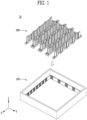
- FIG. 1 is a perspective view schematically illustrating the battery storage tray 10 based on one embodiment of the disclosed technology.
- battery cells 300 are accommodated in the battery storage tray 10 (see FIG. 8 ).
- the battery storage tray 10 may include an accommodating portion 100.
- the battery storage tray 10 may include an insert 200.
- the battery storage tray 10 may include an accommodating portion 100 and an insert 200 embedded in the accommodating portion 100.
- the insert 200 may be embedded in the accommodating portion 100 and may be embedded while coupled and fixed to a portion of the accommodating portion 100.
- the insert 200 may be coupled and fixed to a portion of the accommodating portion 100 or may be decoupled and separated therefrom. Details thereof will be described below.
- FIG. 2 is a perspective view schematically illustrating the accommodating portion 100 of the battery storage tray 10 based on one embodiment of the disclosed technology.
- FIG. 3 is a perspective view schematically illustrating a portion of the accommodating portion 100 of the battery storage tray 10 based on one embodiment of the disclosed technology and is an enlarged view of region A of FIG. 2 .
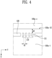
- FIG. 4 schematically illustrates a portion of the accommodating portion 100 of the battery storage tray 10 based on one embodiment of the disclosed technology. Specifically, FIG. 4 is an XY plan view of region A of FIG. 2 .
- FIG. 5 schematically illustrates the accommodating portion 100 of the battery storage tray 10 based on one embodiment of the disclosed technology. Specifically, FIG. 5 is an XY plan view of FIG. 2 .
- the accommodating portion 100 based on one aspect of the disclosed technology will be described in detail using FIGS. 2 to 5 .
- the accommodating portion 100 may include a plastic material.
- the structure of the accommodating portion 100 may be designed appropriately in consideration of the insert 200 to be embedded and the battery cells 300 to be housed.
- structures of components such as a first coupling portion 110 of the accommodating portion 100, which will be described below, may also be appropriately designed.
- the accommodating portion 100 may be implemented by injection molding or the like.
- the accommodating portion 100 may include an inner space 100a in which the insert 200 is embedded and one or more first coupling portions 110 provided in the inner space 100a.
- the accommodating portion 100 based on one aspect of the disclosed technology may have a polyhedral shape with one open surface.
- the accommodating portion 100 may have a hexahedral shape with one open surface.
- the accommodating portion 100 based on another aspect of the disclosed technology may have a polyhedral shape with multiple open surfaces.
- the accommodating portion 100 based on another aspect of the disclosed technology may have a polyhedral shape with one open surface and another surface that is different from the one surface and is at least partially open.
- one terminal 340 of a bidirectional battery cell 300 may protrude outward through the one open surface, and the other terminal 340 may protrude outward through the open portion of the other surface that is at least partially open.
- the other surface may be locally and/or partially open to allow the terminal 340 to protrude outward.
- the accommodating portion 100 may be designed in various different shapes as necessary as long as the terminals 340 can appropriately protrude outward and easily come in contact with a probe used in formation or testing.
- the accommodating portion 100 may have one open surface as described above for the insert 200 to be embedded therein and may include the inner space 100a formed by being surrounded by surfaces other than the open surface. That is, the inner space 100a may be a space formed by being surrounded by surfaces of the accommodating portion 100 other than the open surface thereof for the insert 200 to be embedded therein. Accordingly, the insert 200 may be embedded in the inner space 100a.
- the accommodating portion 100 may include one open surface and another surface that is locally open to allow the terminal 340 to protrude outward.
- the accommodating portion 100 may include outer walls 100b to protect the insert 200 embedded therein from the outside.
- the outer walls 100b may be substantial components that form the inner space 100a described above.
- the accommodating portion 100 may fix the insert 200 embedded therein and may include one or more first coupling portions 110 disposed in the inner space 100a for the insert 200 to be fixed in the accommodating portion 100.
- the insert 200 may be embedded in the inner space 100a of the accommodating portion 100 and fixed therein while being coupled to the first coupling portion 110.
- the first coupling portion 110 may include a plurality of auxiliary coupling portions 111.
- the number of the auxiliary coupling portions 111 is not particularly limited as long as the number is plural but may be determined based on the shape or size of a second coupling portion 220 of the insert 200 which will be described below.
- the number of auxiliary coupling portions 111 of a specific (one) first coupling portion 110 may be four.
- the first coupling portion 110 may include the plurality of auxiliary coupling portions 111, and the plurality of auxiliary coupling portions 111 may be provided to be continuous.
- the word "continuous" may be used to indicate a situation where other components are not present between the auxiliary coupling portions 111. That is, a portion where the auxiliary coupling portions 111 are arranged continuously may be referred to as the first coupling portion 110.
- the accommodating portion 100 may include a plurality of first coupling portions 110 and may optionally include a sidewall 120 configured to partition between adjacent first coupling portions 110.
- a gap between adjacent first coupling portions 110 may be designed appropriately in consideration of the insert 200 to be embedded and the battery cells 300 to be accommodated.
- the accommodating portion 100 includes the sidewall 120, the size (which is a term encompassing the width, length, and height), shape, and position of the sidewall 120 and a gap between the sidewall 120 and the first coupling portion 110 adjacent thereto may also be designed appropriately in consideration of the insert 200 to be embedded and the battery cells 300 to be accommodated.
- the accommodating portion 100 may include a plurality of first coupling portions 110 as described above.
- Each of the first coupling portions 110 may independently include a plurality of auxiliary coupling portions 111, and here, each of the first coupling portions 110 may independently include a different number of auxiliary coupling portions 111.
- one first coupling portion 110 may include four auxiliary coupling portions 111, and another first coupling portion 110 may include seven auxiliary coupling portions 111.
- the number of first coupling portions 110 and the number of auxiliary coupling portions 111 that each of the first coupling portions 110 includes in the accommodating portion 100 based on one aspect of the disclosed technology are determined based on the sizes and numbers of inserts 200 and battery cells 300 to be housed therein, which will be described below, and thus are not particularly limited to specific ranges.
- the auxiliary coupling portions 111 may be arranged in parallel in one direction.
- the first coupling portion 110 may include a plurality of auxiliary coupling portions 111, and the auxiliary coupling portions 111 may be arranged in parallel in the Y-axis direction. That is, all of the auxiliary coupling portions 111 that one first coupling portion 110 includes may be arranged in parallel in one direction.
- the auxiliary coupling portions 111 may have widths, lengths, and heights that are the same as or different from each other. That is, the sizes (which is a term encompassing the widths, lengths, and heights) of the auxiliary coupling portions 111 may be independent from each other.
- the width may be a gap between both ends in the X-axis direction.
- the length may be a gap between both ends in the Y-axis direction.
- the height may be a gap between both ends in the Z-axis direction (see FIG. 3 ).
- the widths, lengths, and heights H of the auxiliary coupling portions 111 may be the same as or different from each other.
- the auxiliary coupling portions 111 of the first coupling portion 110 based on one aspect of the disclosed technology may all have the same heights.
- “same” may mean being substantially the same and may indicate a case where values are different and a difference between the values is within 10% as well as a case where the values are completely the same.
- the height H may be a distance from the lowest position to the highest position in the Z-axis direction.
- the widths, lengths, and heights of the auxiliary coupling portions 111 may be determined based on the shape or size of the second coupling portion 220 of the insert 200 which will be described below.
- the height H of the auxiliary coupling portion 111 may be at least 5% or more or 10% or more of the height of the accommodating portion 100 to secure stability of coupling to the insert 200.
- the height of the accommodating portion 100 may be a distance from the lowest position to the highest position in the accommodating portion 100 in the Z-axis direction.
- a predetermined gap d1 may be present between adjacent auxiliary coupling portions 111.
- a plurality of auxiliary coupling portions 111 may be present in the first coupling portion 110, and the predetermined gap d1 may be present between the auxiliary coupling portions 111 adjacent to each other.
- gaps d1 between different pairs of adjacent auxiliary coupling portions 111 may be different from or the same as each other.
- the size of the gap d1 may be determined based on the shape or size of the second coupling portion 220 of the insert 200 which will be described below.
- the battery storage tray 10 When the predetermined gap d1 is present between adjacent auxiliary coupling portions 111, it is possible to provide the battery storage tray 10 that can accommodate various types (e.g., multiple models) or sizes of battery cells 300 and allows regions for accommodating the battery cells 300 to be implemented through a convenient assembly method.
- the first coupling portion 110 of the battery storage tray 10 may be provided to protrude from one surface 100a-1 in the inner space 100a.
- the first coupling portion 110 may be provided on the one surface 100a-1 in the inner space 100a.
- the first coupling portion 110 may be provided on the one surface 100a-1 and may be provided to protrude from the one surface 100a-1 in the positive Z-axis direction.
- the positive Z-axis direction may be a direction indicated by an arrow of the Z-axis shown in the drawings.
- the protruding shape may be implemented by injection molding or the like.
- the auxiliary coupling portions 111 may be provided to protrude from the one surface 100a-1 in the inner space 100a.
- the auxiliary coupling portions 111 may be provided on the one surface 100a-1 in the inner space 100a.
- the auxiliary coupling portions 111 may be provided on the one surface 100a-1 and may be provided to protrude from the one surface 100a-1 in the positive Z-axis direction.
- the accommodating portion 100 of the battery storage tray 10 may further include other surfaces 100a-c in addition to the one surface 100a-1 on which the first coupling portion 110 is provided.
- the other surfaces 100a-c of the inner space 100a may be other surfaces of the inner space 100a excluding the one surface 100a-1.
- the accommodating portion 100 may include four other surfaces 100a-c that surround the one surface 100a-1 on which the first coupling portion 110 is provided.
- the first coupling portion 110 of the battery storage tray 10 may be provided to face at least some of the other surfaces 100a-c of the inner space 100a.
- any first coupling portion 110 may be provided to face two of the four other surfaces 100a-c while being provided on the one surface 100a-1 of the inner space 100a.
- the first coupling portion 110 in region A may be provided to face two other surfaces 100a-c, which are positioned parallel to the Y-axis direction, while being provided on the one surface 100a-1 of the inner space 100a.
- the auxiliary coupling portions 111 may be provided to face at least some of the other surfaces 100a-c of the inner space 100a as above.
- the auxiliary coupling portions 111 of the first coupling portion 110 may be arranged in parallel in one direction as described above, and the arrangement direction may be a direction facing the other surfaces 100a-c. That is, the auxiliary coupling portions 111 may be arranged in parallel in the Y-axis direction, and the auxiliary coupling portions 111 may be provided to face the other surfaces 100a-c positioned parallel to the Y-axis direction.
- the first coupling portion 110 of the battery storage tray 10 based on one aspect of the disclosed technology may not come in contact with the other surfaces 100a-c in the inner space 100a.
- the auxiliary coupling portions 111 may not come in contact with the other surfaces 100a-c in the inner space 100a.
- the first coupling portion 110 of the battery storage tray 10 may be provided with a predetermined gap d2 from the other surface 100a-c adjacent thereto.
- the other surface 100a-c adjacent thereto may be the other surface 100a-c that is the closest to the first coupling portion 110, which is provided on the one surface 100a-1 of the inner space 100a, while facing the first coupling portion 110.
- the auxiliary coupling portions 111 of the first coupling portion 110 may be provided with the predetermined gap d2 from the other surface 100a-c adjacent thereto.
- the size of the gap d2 may be determined based on the shape or size of the second coupling portion 220 of the insert 200 which will be described below.
- the predetermined gap d2 is present between the first coupling portion 110 and the other surface 100a-c adjacent thereto, it is possible to provide the battery storage tray 10 that can accommodate various types (e.g., multiple models) or sizes of battery cells 300 and allows regions for accommodating the battery cells 300 to be implemented through a convenient assembly method.
- the first coupling portion 110 based on one aspect of the disclosed technology may be provided on the one surface 100a-1 in the inner space 100a, and the one surface 100a-1 may include one or more edges 100a-1E. Due to the edges 100a-1E, a closed area in which the first coupling portion 110 may be provided may be formed. In some implementations, the edges 100a-1E may indicate boundaries of the one surface 100a-1 itself or indicate boundary lines between the one surface 100a-1 and the other surfaces 100a-c.
- the edges 100a-1E may be straight or curved.
- the number of edges 100a-1E may be calculated based on whether the directions and positions of the straight lines are different, and when the edges 100a-1E are curved, the number of edges 100a-1E may be calculated based on whether the curvatures and positions of the curved lines are different.
- the positions may be described as different from each other when any one edge 100a-1E should be moved to overlap another edge 100a-1E in the same coordinate system.
- the one surface 100a-1 of the accommodating portion 100 has four straight lines with different directions and positions and thus may be described as including four straight edges 100a-1E.
- one or more first coupling portions 110 may be provided along each edge 100a-1E.
- being provided along the edge 100a-1E means being provided parallel to the edge 100a-1E.
- the one surface 100a-1 based on one aspect of the disclosed technology may include a plurality of edges 100a-1E. In some implementations, the one surface 100a-1 may include one or more pairs of edges 100a-1E that face each other.
- the one surface 100a-1 includes two x edges 100a-1Ex that are parallel to the X-axis and two y edges 100a-1Ey that are parallel to the Y-axis. That is, referring to FIG. 5 , the one surface 100a-1 includes two pairs of edges 100a-1E that face each other and includes a total of four straight edges 100a-1E. In some implementations, referring to FIG. 5 , seven first coupling portions 110 are provided along each x edge 100a-1Ex, and five first coupling portions 110 are provided along each y edge 100a-1Ey.
- the numbers and positions of the first coupling portions 110 provided along the edges 100a-1E that face each other may correspond to each other. That is, the number and positions of the first coupling portions 110 provided along one x edge 100a-1Ex and the number and positions of the first coupling portions 110 provided along the other x edge 100a-1Ex that faces the one x edge 100a-1Ex may correspond to each other.
- “correspond” may mean that the numbers of first coupling portions 110 are the same, and the positions thereof are symmetrical.
- the numbers and positions of the first coupling portions 110 provided along the edges 100a-1E that face each other correspond to each other in this way, it may be advantageous in implementing regions for accommodating the battery cells 300 through a convenient assembly method.
- this is only an example, and the numbers and positions of the first coupling portions 110 may vary based on design.
- the first coupling portion 110 based on one aspect of the disclosed technology may be provided on the one surface 100a-1 in the inner space 100a and may be provided with a predetermined gap d3 from an edge 100a-1E of the one surface 100a-1 that is adjacent thereto.
- the edge 100a-1E adjacent thereto may be the edge 100a-1E that is the closest to the first coupling portion 110 while facing the first coupling portion 110.
- the size of the gap d3 may be determined based on the shape or size of the second coupling portion 220 of the insert 200 which will be described below.
- the above-described predetermined gap d2 between the first coupling portion 110 and the other surface 100a-c adjacent thereto and the predetermined gap d3 between the first coupling portion 110 and the edge 100a-1E adjacent thereto may be the same.
- the battery storage tray 10 When the predetermined gap d3 is present between the first coupling portion 110 and the edge 100a-1E adjacent thereto, it is possible to provide the battery storage tray 10 that can accommodate various types (e.g., multiple models) or sizes of battery cells 300 and allows regions for accommodating the battery cells 300 to be implemented through a convenient assembly method.
- the auxiliary coupling portions 111 may be provided on the one surface 100a-1 in the inner space 100a and may be provided with the predetermined gap d3 from an edge 100a-1E of the one surface 100a-1 that is adjacent thereto.
- the sizes of the above-described gaps d1, d2, and d3 may be determined based on the shape or size of the second coupling portion 220 of the insert 200 which will be described below.
- representative values of the gaps d1, d2, and d3 may indicate average values when the values are not constant due to varying the position at which measurement is performed or the object to be measured.
- a plurality of auxiliary coupling portions 111 may be provided, and the gap d3 between the auxiliary coupling portion 111 and the edge 100a-1E adjacent thereto may be the same or different for each auxiliary coupling portion 111.
- the size thereof may be a representative value of the gap d3, and when the gap d3 between the auxiliary coupling portion 111 and the edge 100a-1E adjacent thereto is different in one or more auxiliary coupling portions 111, the size of an arithmetic mean of the gaps d3 may be a representative value of the gap d3.
- FIG. 6 is a perspective view schematically illustrating the insert 200 of the battery storage tray 10 based on one embodiment of the disclosed technology.
- FIG. 7 is a perspective view schematically illustrating a portion of the insert 200 of the battery storage tray 10 based on one embodiment of the disclosed technology. Specifically, FIG. 7 is an enlarged view of region B of FIG. 6 .
- the battery cells 300 may be housed in the insert 200 of the battery storage tray 10 based on one aspect of the disclosed technology.
- the insert 200 may be coupled to the accommodating portion 100 to form regions for accommodating the battery cells 300, and the battery cells 300 may be housed in the regions for accommodating the battery cells 300 (battery storage portions 260 to be described below, see FIG. 8 ).
- the battery storage tray 10 in which the battery cells 300 are housed may be mainly used in the activation process or the like.
- the insert 200 may include a plastic material.
- the structure of the insert 200 may be designed appropriately in consideration of the type or size of the battery cells 300 to be accommodated.
- structures of components such as the second coupling portion 220 of the insert 200, which will be described below, may also be appropriately designed.
- the insert 200 may be implemented by injection molding or the like.
- the insert 200 may include storage grooves 210.
- the storage grooves 210 may be grooves for accommodating at least a portion of each battery cell 300.
- the storage grooves 210 may allow the battery storage tray 10 to have the battery storage portions 260 for accommodating the battery cells 300 (see FIG. 8 ).
- the insert 200 may include the second coupling portion 220 that may be coupled to the first coupling portion 110 included in the accommodating portion 100. That is, when the insert 200 is embedded in the accommodating portion 100, the first coupling portion 110 and the second coupling portion 220 may be coupled, and the insert 200 may be fixed to the inner space 100a of the accommodating portion 100. Conversely, the first coupling portion 110 and the second coupling portion 220 coupled to each other may be decoupled, and due to the decoupling thereof, the accommodating portion 100 and the insert 200 may be separated.
- the insert 200 may include the second coupling portion 220 configured to be coupled to one or more auxiliary coupling portions 111 selected from the plurality of auxiliary coupling portions 111 included in one first coupling portion 110. That is, one first coupling portion 110 may include a plurality of auxiliary coupling portions 111 as described above (see FIGS. 2 to 5 ), and the second coupling portion 220 of the insert 200 may be coupled to one or more of the plurality of auxiliary coupling portions 111. When the second coupling portion 220 is coupled to one or more of the plurality of auxiliary coupling portions 111, the insert 200 may be coupled and fixed to the accommodating portion 100. Details of coupling between the first coupling portion 110 of the accommodating portion 100 and the second coupling portion 220 of the insert 200 will be described below.
- the insert 200 may include a support body 230 having the second coupling portion 220.
- the second coupling portion 220 may be provided at an appropriate position on the support body 230 for space utilization when the insert 200 is coupled to the accommodating portion 100 and the battery cells 300 are housed.
- the insert 200 may include a plurality of second coupling portions 220 for stable coupling with the accommodating portion 100.
- the insert 200 may include the support body 230 having the second coupling portions 220 provided at both ends.
- the support body 230 is a component for supporting each component of the insert 200 and may have a shape that is long in the longitudinal direction, and for example, may have the shape of a beam or a pipe but is not limited thereto. That is, referring to FIG. 6 , in the support body 230 having the shape that is long in the longitudinal direction along the Y-axis, the second coupling portions 220 may be positioned at both ends along the Y-axis.
- the second coupling portions 220 may be integrally formed with the support body 230 and may be joined and coupled thereto by welding, adhesion, or hardware (bolts or the like).
- the second coupling portions 220 and the support body 230 may be integrally formed.
- the insert 200 may include a plurality of storage frame portions 240 disposed on the support body 230 and including a bent member 250 that is at least partially bent.
- a plurality of bent members 250 each of which is at least partially bent may be provided on the support body 230, and in this way, the insert 200 may also include the plurality of storage frame portions 240 including the bent members 250.
- the bent members 250 may protrude from one surface of the support body 230.
- the bent members 250 may be integrally formed with the support body 230 and may be joined and coupled thereto by welding, adhesion, or hardware (bolts or the like).
- the bent members 250 and the support body 230 may be integrally formed.
- the storage grooves 210 may be provided in the storage frame portions 240 of the insert 200 based on one aspect of the disclosed technology through the structures of the bent members 250.
- the storage frame portion 240 may include one bent member 250 or a plurality of bent members 250 and may have various forms of storage grooves 210 based on the structures of the bent members 250.
- the number of times the bent member 250 is bent and the direction in which the bent member 250 is bent may be independent for each bent member 250 provided on the support body 230.
- the number of times the bent member 250 is bent and the direction in which the bent member 250 is bent may be designed appropriately in consideration of the type or size of the battery cells 300 to be accommodated.
- the insert 200 may include the plurality of storage frame portions 240, and the structure and shape of the storage frame portion 240 may be independent for each storage frame portion 240.
- the storage frame portions 240 may include a first storage frame portion 240a including a plurality of first bent members 250a and a second storage frame portion 240b including a single second bent member 250b. That is, the bent members 250 may include one or more selected from the group consisting of the plurality of first bent members 250a and the single second bent member 250b.
- the ordinals added to the beginning of "first bent members 250a" and "second bent member 250b" are simply added for distinguishing the two, regardless of the order or importance.
- the first storage frame portion 240a may include the storage groove 210 due to the plurality of first bent members 250a.
- the plurality of first bent members 250a may be provided while spaced apart from each other, and bent portions of the first bent members 250a may be arranged to face each other.
- the bent portions may be protruding portions 250a-1. Referring to FIG. 6 , when the protruding portions 250a-1 of the first bent members 250a are arranged to face each other as described above, the storage groove 210 may be formed naturally.
- a passage region 250a-2 may be formed between the protruding portions 250a-1.
- first storage frame portion 240a has been defined as the storage frame portion 240 including the plurality of first bent members 250a
- the storage frame portion 240 having the passage region 250a-2 formed therein as described above may be the first storage frame portion 240a.
- a separation gap between the plurality of first bent members 250a may be determined based on the shape and size of the battery cells 300.
- the second storage frame portion 240b may include the storage groove 210 due to the single second bent member 250b.
- the single second bent member 250b may be provided, and the second bent member 250b may have a shape that is bent multiple times.
- the positions at which the second bent member 250b is bent and the number of times the second bent member 250b is bent may be determined based on the shape and size of the battery cells 300. That is, the second bent member 250b may be bent multiple times and form the storage groove 210 in which at least a portion of the battery cell 300 may be housed.
- the second storage frame portion 240b may include a protruding portion 240b-1 that protrudes more than the first storage frame portion 240a due to the bent shape of the second bent member 250b.
- the second storage frame portion 240b includes the protruding portion 240b-1 that protrudes more than the first storage frame portion 240a, and the protruding portion 240b-1 protrudes in the negative X-axis direction.
- the negative X-axis direction may be a direction that is 180° from the positive X-axis direction.
- the insert 200 may include the first storage frame portion 240a and the second storage frame portion 240b.
- the insert 200 may include the first storage frame portion 240a and the second storage frame portion 240b and may include a structure in which the first storage frame portion 240a and the second storage frame portion 240b are sequentially arranged. That is, the insert 200 may include a structure in which, in the support body 230 having a shape that is long in the longitudinal direction, the first storage frame portion 240a and the second storage frame portion 240b are sequentially arranged while spaced apart from each other in the longitudinal direction of the support body 230.
- a separation gap between the first storage frame portion 240a and the second storage frame portion 240b may be determined based on the shape and size of the battery cells 300.
- the number of structures in which the first storage frame portion 240a and the second storage frame portion 240b are sequentially arranged while spaced apart from each other may be plural.
- the separation gap between the first storage frame portion 240a and the second storage frame portion 240b may be independent for each structure.
- the separation distances may be the same as or different from each other.
- the number of structures in which the first storage frame portion 240a and the second storage frame portion 240b are sequentially arranged while spaced apart from each other may be plural, and the separation gap between the first storage frame portion 240a and the second storage frame portion 240b may be the same for each structure.
- the number of structures in which the first storage frame portion 240a and the second storage frame portion 240b are sequentially arranged while spaced apart from each other may be plural, and an appropriate separation distance may also be present between the structures that are sequentially arranged.
- the separation distances may be independent from one another, and for example, the separation distances may be the same as or different from one another. In consideration of space efficiency, the separation distances between the sequentially arranged structures may be the same.
- the support body 230 has the shape that is long in the direction along the Y-axis, and the insert 200 includes a plurality of structures in which the first storage frame portion 240a and the second storage frame portion 240b are sequentially arranged in this order in the direction along the Y-axis.
- the insert 200 may continuously include the structures in which the first storage frame portion 240a and the second storage frame portion 240b are sequentially arranged in this order.
- “may continuously include” may mean that the structure in which the first storage frame portion 240a and the second storage frame portion 240b are sequentially arranged in this order is repeated at least two or more times.
- the first storage frame portion 240a, the second storage frame portion 240b, the first storage frame portion 240a, the second storage frame portion 240b, and the first storage frame portion 240a may be sequentially arranged in this order.
- separation distances between different pairs of the first storage frame portion 240a and the second storage frame portion 240b may be independent from one another and may be the same as each other referring to FIG. 6 .
- the insert 200 may include a plurality of structures in which the first storage frame portion 240a and the second storage frame portion 240b are sequentially arranged while spaced apart from each other and may continuously include the structures that are sequentially arranged.
- the separation distances between the sequentially arranged structures may be independent from one another and may be the same as each other referring to FIG. 6 .
- the insert 200 may include the structure in which the first storage frame portion 240a and the second storage frame portion 240b are sequentially arranged in this order or may continuously include structures in which the first storage frame portion 240a and the second storage frame portion 240b are sequentially arranged in this order, but it is not necessary for the insert 200 to start with the first storage frame portion 240a or end with the second storage frame portion 240b.
- the structure of the insert 200 may be determined based on the shape and size of the battery cells 300.
- the insert 200 includes a structure in which the first storage frame portion 240a, the second storage frame portion 240b, the first storage frame portion 240a, the second storage frame portion 240b, and the first storage frame portion 240a, the second storage frame portion 240b, and the first storage frame portion 240a are sequentially arranged in this order. That is, referring to FIG. 6 , the insert 200 may include the structure in which the first storage frame portion 240a and the second storage frame portion 240b are sequentially arranged in this order and may also include a structure in which such structures are continuously arranged.
- the storage groove 210 may be provided due to protruding portions 240b-1 of one second storage frame portion 240b and another second storage frame portion 240b adjacent thereto.
- the storage groove 210 in which at least a portion of the battery cell 300 may be housed may be provided between adjacent second storage frame portions 240b, each of which includes the protruding portion 240b-1 protruding in the negative X-axis direction.
- the insert 200 may include the storage frame portion 240 in which the storage groove 210 is provided by the bent member 250 itself.
- the first storage frame portion 240a may have the storage groove 210 provided therein by the plurality of first bent members 250a
- the second storage frame portion 240b may have the storage groove 210 provided therein by the single second bent member 250b.
- the insert 200 may have the storage groove 210 provided between the protruding portions 240b-1 of the second storage frame portions 240b when the first storage frame portions 240a and the second storage frame portions 240b are arranged appropriately.
- the insert 200 may include the second coupling portion 220 that has an appropriate shape in consideration of the shape and size of the first coupling portion 110 of the accommodating portion 100.
- the second coupling portion 220 may be provided at the support body 230, and specifically, the second coupling portions 220 may be positioned at both ends of the support body 230.
- the second coupling portion 220 may include a fixed portion 221.
- the fixed portion 221 may pass through the gap d2 between the first coupling portion 110 and the other surface 100a-c adjacent thereto. That is, a portion of the second coupling portion 220 may pass through the gap d2 between the first coupling portion 110 and the other surface 100a-c adjacent thereto as described above (see FIG. 2 ), and the portion of the second coupling portion 220 may be the fixed portion 221.
- the accommodating portion 100 and the insert 200 may be more stably coupled.
- the fixed portion 221 may pass through the predetermined gap d3 between the first coupling portion 110 and the edge 100a-1E adjacent thereto. That is, a portion of the second coupling portion 220 may pass through the predetermined gap d3 between the first coupling portion 110 and the edge 100a-IE adjacent thereto, and the portion of the second coupling portion 220 may be the fixed portion 221.
- the accommodating portion 100 and the insert 200 may be more stably coupled.
- the fixed portion 221 may pass through both the gap d2 and the gap d3.
- the second coupling portion 220 may include a coupling through-hole 222. At least a portion of the first coupling portion 110 may pass through the coupling through-hole 222 and fix the insert 200 and the accommodating portion 100. Specifically, the first coupling portion 110 provided to protrude from the one surface 100a-1 of the accommodating portion 100 may pass through the coupling through-hole 222 of the insert 200.
- the second coupling portion 220 may include a connecting portion 223.
- the connecting portion 223 may mechanically connect the support body 230 and the fixed portion 221 and form the coupling through-hole 222.
- the second coupling portion 220 may include a plurality of connecting portions 223. That is, referring to FIG. 7 , the second coupling portion 220 may include a first connecting portion 223a and a second connecting portion 223b.
- first connecting portion 223a and “second connecting portion 223b” are simply added for distinguishing the two, regardless of the order or importance.
- the first connecting portion 223a and the second connecting portion 223b may be configured to mechanically connect the support body 230 and the fixed portion 221 and face each other while spaced apart from each other, and the coupling through-hole 222 may be provided between the first connecting portion 223a and the second connecting portion 223b.
- a portion of the second coupling portion 220 may pass through the gap d1 between the auxiliary coupling portions 111.
- the portion of the second coupling portion 220 may be the connecting portion 223 described above, and the connecting portion 223 may pass through the gap d1.
- the connecting portion 223 may also pass through a gap between the auxiliary coupling portion 111 and the sidewall 120 as well as the gap d1 between the auxiliary coupling portions 111.
- FIG. 8 is a perspective view schematically illustrating an example of the battery storage tray 10 based on one embodiment of the disclosed technology.
- FIG. 8 is a view illustrating a state in which the plurality of inserts 200 are coupled to the accommodating portion 100 in FIG. 1 .
- the accommodating portion 100 and the plurality of inserts 200 are coupled to each other, and as will be described below, the battery storage portions 260 for accommodating the battery cells 300 may be provided due to the inserts 200 coupled to the accommodating portion 100.
- the sizes of the battery storage portions 260 may be determined based on the sizes of the storage grooves 210 of the inserts 200, and the sizes of the storage grooves 210 may be designed in consideration of the sizes of the battery cells 300.
- a single battery storage portion 260 or a plurality of battery storage portions 260 may be provided, and the housed battery cells 300 may be equal in number to the battery storage portions 260.
- FIG. 9 schematically illustrates an example of the battery storage tray 10 based on one embodiment of the disclosed technology.
- FIG. 9 is an XY plan view of FIG. 8 .
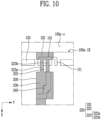
- FIG. 10 schematically illustrates an example of the battery storage tray 10 based on one embodiment of the disclosed technology.
- FIG. 10 is an XY plan view of FIG. 8 .
- FIG. 11 schematically illustrates an example of the battery storage tray 10 based on one embodiment of the disclosed technology.
- FIG. 11 is an XY plan view of FIG. 8 .
- the second coupling portion 220 of the insert 200 may be coupled to the first coupling portion 110.
- the inserts 200 may slide downward in the negative Z-axis direction and be coupled to the accommodating portion 100.
- the first coupling portion 110 and the second coupling portion 220 may be coupled to each other as one or more of the auxiliary coupling portions 111 of the first coupling portion 110 that protrude to have an appropriate height from the one surface 100a-1 in the inner space 100a pass through the coupling through-hole 222 of the second coupling portion 220.
- the fixed portion 221 of the second coupling portion 220 may pass through the gap d2 between the first coupling portion 110 and the other surface 100a-c adjacent thereto. In some implementations, referring to FIG. 9 , the fixed portion 221 may also pass through the predetermined gap d3 between the first coupling portion 110 and the edge 100a-1E adjacent thereto.
- the connecting portions 223 of the second coupling portion 220 may pass through the gap d1 between the auxiliary coupling portions 111 and the gap between the auxiliary coupling portion 111 and the sidewall 120.
- the first connecting portion 223a of the connecting portions 223 may pass through the gap between the auxiliary coupling portion 111 and the sidewall 120
- the second connecting portion 223b may pass through the gap d1 between the auxiliary coupling portions 111.
- the insert 200 may include the second coupling portion 220 configured to be coupled to one or more auxiliary coupling portions 111 selected from the plurality of auxiliary coupling portions 111 included in one first coupling portion 110. That is, the second coupling portion 220 of the insert 200 may be coupled to one or more auxiliary coupling portions 111 selected from the plurality of auxiliary coupling portions 111, in consideration of the type or size of the battery cells 300.
- the size (width, length, and the like) of the battery storage portion 260 to be described below may be changed. That is, the size of the battery storage portion 260 may be designed in consideration of the type or size of the battery cells 300 to be housed in the battery storage tray 10, and the size of the battery storage portion 260 may vary based on the auxiliary coupling portion 111 that passes through the coupling through-hole 222.
- the second coupling portion 220 of the insert 200 may be coupled to the first coupling portion 110 by the method shown in FIG. 9 .
- the connecting portions 223 of the second coupling portion 220 pass through the gaps d1 between the auxiliary coupling portions 111. That is, the first connecting portion 223a of the connecting portions 223 may pass through the gap d1 between one pair of auxiliary coupling portions 111, and the second connecting portion 223b may pass through the gap d1 between another pair of auxiliary coupling portions 111.
- first coupling portion 110 and the second coupling portion 220 may be coupled to each other through the above method.
- the plurality of inserts 200 may be coupled to the first coupling portion 110.
- the plurality of second coupling portions 220 may be coupled to the first coupling portion 110.
- the plurality of inserts 200 coupled to one first coupling portion 110 may have or not have certain intervals therebetween. That is, the plurality of inserts 200 may at least partially come in contact with each other or not come in contact with each other.
- the inserts 200 may be implemented by injection molding or the like.
- the plurality of inserts 200 may be coupled to the first coupling portion 110 while spaced apart at minimum intervals from each other.
- the plurality of inserts 200 may be easier to couple and decouple the inserts 200 and the first coupling portion 110 to and from each other, and damage to the inserts 200 or the first coupling portion 110 may be minimized.
- the plurality of inserts 200 may be in contact with each other in consideration of space utilization.
- the relationship between the plurality of inserts 200 is not limited to the above.
- At least two inserts 200 may have structures symmetrical to each other.
- two inserts 200 coupled to the first coupling portion 110 have structures that are symmetrical to each other about the X-axis.
- the battery storage portion 260 to be described below may be provided in the battery storage tray 10.
- FIG. 12 schematically illustrates an example of the battery storage tray 10 based on one embodiment of the disclosed technology.
- FIG. 12 is an XY plan view of FIG. 8 .
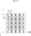
- FIG. 13 is an XY plan view schematically illustrating examples of the battery cells 300 housed in the battery storage tray 10 based on one embodiment of the disclosed technology.
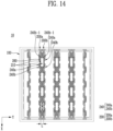
- FIG. 14 schematically illustrates the battery storage tray 10 based on one embodiment of the disclosed technology and is an XY plan view of FIG. 8 .
- FIG. 15 is an XY plan view schematically illustrating examples of the battery cells 300 housed in the battery storage tray 10 based on one embodiment of the disclosed technology.
- FIG. 16 is an XY plan view schematically illustrating an example of the battery storage tray 10 based on one embodiment of the disclosed technology.
- FIG. 17 is an XY plan view schematically illustrating examples of the battery cells 300 housed in the battery storage tray 10 based on one embodiment of the disclosed technology.
- the inserts 200 may be provided across the inner space 100a of the accommodating portion 100. Referring to FIGS. 1 and 8 , the inserts 200 may be provided across the inner space 100a of the accommodating portion 100. In some implementations, referring to FIG. 8 , the inserts 200 may be provided across the inner space 100a of the accommodating portion 100 in the X-axis direction.
- the inserts 200 may be provided across the inner space 100a of the accommodating portion 100 in one specific direction. Referring to FIG. 12 , one or more inserts 200 may be provided across the inner space 100a of the accommodating portion 100 in the X-axis direction.
- the battery storage tray 10 may include the plurality of inserts 200 as described above. In some implementations, at least two or more of the plurality of inserts 200 may be provided across the inner space 100a of the accommodating portion 100 in the same direction. In some implementations, all of the plurality of inserts 200 may be provided across the inner space 100a of the accommodating portion 100 in the same direction. When all of the plurality of inserts 200 are provided in the same direction, the battery storage tray 10 may efficiently utilize space and store more battery cells 300.
- the plurality of inserts 200 may include a first insert 200a and a second insert 200b, and the first insert 200a and the second insert 200b may be positioned adjacent to each other while having structures symmetrical to each other.
- first insert 200a and second insert 200b are simply added for distinguishing the two, regardless of the order or importance.
- the first insert 200a and the second insert 200b having structures symmetrical to each other may mean that the first insert 200a and the second insert 200b are symmetrical about the direction across the inner space 100a at the center between the first insert 200a and the second insert 200b (when the first insert 200a and the second insert 200b are in contact, a contact line thereof).
- the first insert 200a and the second insert 200b being adjacent to each other may mean that another insert 200 is not present between the first insert 200a and the second insert 200b.
- the battery storage tray 10 may include the plurality of inserts 200.
- at least two or more or all of the plurality of inserts 200 may be provided across the inner space 100a of the accommodating portion 100 in the same direction.
- all of the plurality of inserts 200 may be provided across the inner space 100a of the accommodating portion 100 in the X-axis direction, and the first insert 200a and the second insert 200b, which are some of the plurality of inserts 200, may be positioned adjacent to each other while having structures symmetrical to each other.
- the battery storage portion 260 for accommodating the battery cell 300 may be included between the first insert 200a and the second insert 200b.
- the battery storage portion 260 may be positioned in a region in which the storage groove 210 of the first insert 200a and the storage groove 210 of the second insert 200b face each other.
- the inserts 200 may include the first insert 200a and the second insert 200b.
- the first insert 200a and the second insert 200b may be positioned adjacent to each other while having structures symmetrical to each other.
- the battery storage portion 260 may be positioned in a region in which the storage groove 210 provided in the first storage frame portion 240a of the first insert 200a and the storage groove 210 provided in the first storage frame portion 240a of the second insert 200b face each other.
- the battery storage portion 260 may be positioned in a region in which the storage groove 210 provided in the second storage frame portion 240b of the first insert 200a and the storage groove 210 provided in the second storage frame portion 240b of the second insert 200b face each other.
- all of the dotted boxes may represent the battery storage portions 260, and the battery cells 300 may be housed in the battery storage portions 260.
- a width W and a length L of the battery storage portion 260 provided due to the storage grooves 210 of the first insert 200a and the second insert 200b may vary based on appropriate structural design of each insert 200, positions of the inserts 200 and the auxiliary coupling portions 111 to which the inserts 200 are coupled, and the like. That is, by changing the structural design, coupling positions, and the like of the inserts 200, the battery storage tray 10 may include the battery storage portions 260 whose width W and length L are suitable for the battery cells 300 to be housed therein.
- the contents related to the width W and the length L of the battery storage portions 260 are as described above, and thus description thereof will be omitted below unless contents are different.
- the width W may be a size between two points on the battery storage portion 260 between which a linear distance is the largest
- the length L may be perpendicular to the width W and may be a size between two points on the battery storage portion 260 between which a linear distance is the shortest. That is, in the battery storage portion 260, the width W may be larger than the length L.
- both of them may be referred to as either the width W or the length L.
- the battery cells 300 may each include an outer material 310 that may have an electrode assembly 320 embedded therein.
- the battery cells 300 may each include one or more terminals 340 (see FIGS. 18 and 19 ) that protrude in one direction of the outer material 310 in a direction not facing the inner space 100a of the accommodating portion 100 while electrically connected to the electrode assembly 320. That is, in FIG. 13 , the battery cells 300 may be housed in the battery storage portions 260 so that at least some of the terminals 340 of the battery cells 300 protrude in the positive Z-axis direction.
- formation or testing that may be performed in the activation process may be more easily performed.
- formation or testing that may be performed in the activation process may be more easily performed as a probe used in the formation or testing comes in contact with the protruding terminals 340. Details of the battery cells 300 will be described below.
- the shape of the battery storage portion 260 may be determined based on the shape of the outer material 310 of the battery cell 300 to be housed. Referring to FIG. 13 , when the outer material 310 of the battery cell 300 has a hexahedral shape which is prismatic, the battery storage portion 260 may have an appropriate shape to store the hexahedral shape which is prismatic, and to this end, the storage frame portions 240 or the bent members 250 of the inserts 200 may be designed to be suitable therefor.
- the battery cells 300 housed in the battery storage portions 260 based on one aspect of the disclosed technology may be housed in one direction.
- the direction may be based on the width W direction of the battery storage portions 260. That is, referring to FIG. 13 , the battery cells 300 housed in the battery storage portions 260 may be described as housed in the Y-axis direction, which is the width W direction of the battery storage portions 260.
- a direction in which the battery cells 300 are housed may be determined based on a width W direction of the battery cells 300.
- the width W of the battery cells 300 may be a size of a long side on a plane (XY plane) excluding a direction in which the terminals 340 of the battery cells 300 protrude (for example, the Z-axis direction).
- the length L may be less than the width W and may be a size of a short side.
- a direction in which the battery cells 300 are housed may be determined based on a width W direction of the accommodating portion 100.
- the width W of the accommodating portion 100 may be a size of a long side in a plane (XY plane) excluding a direction in which the terminals 340 of the battery cells 300 protrude (for example, the Z-axis direction).
- the length L may be less than the width W and may be a size of a short side.
- a direction in which the battery cells 300 are housed may not be determined.
- a state of the battery storage tray 10 illustrated in FIG. 14 shows that, although the battery storage tray 10 has the same structure as the battery storage tray 10 illustrated in FIG. 12 , the battery storage portions 260 may be interpreted differently.
- the inserts 200 may include the first insert 200a and the second insert 200b, and the first insert 200a and the second insert 200b may be positioned adjacent to each other while having structures symmetrical to each other.
- the inserts 200 in FIG. 14 continuously include structures in which the first storage frame portion 240a and the second storage frame portion 240b are sequentially arranged in this order.
- the storage groove 210 may be provided due to protruding portions 240b-1 of one second storage frame portion 240b and another second storage frame portion 240b adjacent thereto (see FIGS. 6 and 14 ).
- the battery storage portion 260 may be positioned in a region in which the storage groove 210 provided due to the above-described protruding portions 240b-1 on the first insert 200a and the storage groove 210 provided due to the above-described protruding portions 240b-1 on the second insert 200b face each other.
- all of the dotted boxes may represent the battery storage portions 260, and the battery cells 300 may be housed in the battery storage portions 260.
- FIG. 15 a state in which all of the battery cells 300 are housed in the battery storage portions 260 illustrated in FIG. 14 is shown.
- the housed battery cells 300 may be described as housed in the X-axis direction, which is the width W direction of the battery storage portions 260.
- certain directions in which the battery cells 300 are housed may allow more battery cells 300 to be housed.
- FIG. 13 when the battery cells 300 are housed in the Y-axis direction, a maximum of twenty-eight battery cells 300 may be housed.
- FIG. 15 when the battery cells 300 are housed in the X-axis direction, a maximum of twelve battery cells 300 may be housed.
- the inserts 200 may be provided across the inner space 100a of the accommodating portion 100 in one specific direction. Referring to FIG. 16 , one or more inserts 200 may be provided across the inner space 100a of the accommodating portion 100 in the Y-axis direction. Since the inserts 200 are the same as described above except for the direction in which the inserts 200 are provided across the inner space 100a of the accommodating portion 100, further description of the inserts 200 will be omitted below.
- all of the plurality of inserts 200 may be provided across the inner space 100a of the accommodating portion 100 in the Y-axis direction, and the first insert 200a and the second insert 200b, which are some of the plurality of inserts 200, may be positioned adjacent to each other while having structures symmetrical to each other.
- the inserts 200 in FIG. 16 continuously include structures in which the first storage frame portion 240a and the second storage frame portion 240b are sequentially arranged in this order.
- the storage groove 210 may be provided due to protruding portions 240b-1 of one second storage frame portion 240b and another second storage frame portion 240b adjacent thereto (see FIGS. 6 and 16 ). That is, the battery storage portion 260 may be positioned in a region in which the storage groove 210 provided due to the above-described protruding portions 240b-1 on the first insert 200a and the storage groove 210 provided due to the above-described protruding portions 240b-1 on the second insert 200b face each other.
- all of the dotted boxes may represent the battery storage portions 260, and the battery cells 300 may be housed in the battery storage portions 260.
- FIG. 17 a state in which all of the battery cells 300 are housed in the battery storage portions 260 illustrated in FIG. 16 is shown.
- the housed battery cells 300 may be described as housed in the Y-axis direction, which is the width W direction of the battery storage portions 260. Referring to FIG. 17 , when the battery cells 300 are housed in the Y-axis direction, a maximum of twenty-eight battery cells 300 may be housed.
- the maximum number N1 of the battery cells 300 that are able to be housed in one direction when all of the plurality of inserts 200 are provided across the inner space 100a of the accommodating portion 100 in a first direction and the maximum number N2 of the battery cells 300 that are able to be housed in the one direction when all of the plurality of inserts 200 are provided across the inner space 100a of the accommodating portion 100 in a second direction may be equal to each other.
- the maximum number N1 of the battery cells 300 that are able to be housed in the Y-axis direction may be twenty-eight.
- the maximum number N2 of the battery cells 300 that are able to be housed in the Y-axis direction may also be twenty-eight.
- the first direction and the second direction may be perpendicular to each other.
- an array P1 of the battery storage portions 260 when the plurality of inserts 200 are provided across the inner space 100a of the accommodating portion 100 in the first direction to allow the maximum number N1 of the battery cells 300 to be housed and an array P2 of the battery storage portions 260 when the plurality of inserts 200 are provided across the inner space 100a of the accommodating portion 100 in the second direction to allow the maximum number N2 of the battery cells 300 to be housed may be the same as each other.
- an array of the battery storage portions 260 may be positions of rows and columns of all of the battery storage portions 260 provided in the battery storage tray 10 and widths W and lengths L related to the positions.
- the array P1 of the battery storage portions 260 when the plurality of inserts 200 are provided across the inner space 100a of the accommodating portion 100 in the X-axis direction (that is, the first direction) to allow the maximum number N1 of the battery cells 300 to be housed is shown with dotted boxes.
- the array P2 of the battery storage portions 260 when the plurality of inserts 200 are provided across the inner space 100a of the accommodating portion 100 in the Y-axis direction (that is, the second direction) to allow the maximum number N2 of the battery cells 300 to be housed is shown with dotted boxes.
- the array P1 and the array P2 may be the same. In this way, formation or testing that may be performed in the activation process may be more easily performed.
- the centers of the terminals 340 of the battery cells 300 may be the same. Since the centers of the terminals 340 are the same in the same arrays P1 and P2, while performing formation or other tests, even when the type of the battery cells 300 changes, it may not be necessary to change the structures of the accommodating portion 100 and/or the inserts 200 themselves or change the position of the probe. In this way, it is possible to provide the battery storage tray 10 that can accommodate various types (e.g., multiple models) of battery cells 300 and allows regions for accommodating the battery cells 300 to be implemented through a convenient assembly method.
- FIGS. 18 and 19 are exploded perspective views schematically illustrating a structure of the battery cell 300 to be housed in the battery storage tray 10 based on one embodiment of the disclosed technology.
- the structure of the battery cell 300 based on one aspect of the disclosed technology may be known.
- the battery cell 300 may have a structure in which the outer material 310 is embedded with the electrode assembly 320 and filled with an electrolyte.
- the battery cell 300 may include electrodes (a cathode 321 and an anode 322) and a solid electrolyte layer, and the solid electrolyte layer may serve as a separator 323 while allowing passage of an electron transport material.
- the electron transport material may be lithium ions (Li+).
- the battery cell 300 including the solid electrolyte layer may be an all-solid battery.
- the electrode assembly 320 may include electrodes.
- the electrodes may be a term encompassing the cathode 321 and the anode 322.
- the electrode assembly 320 may include the separator 323 to prevent short circuit between the cathode 321 and the anode 322.
- the separator 323 may be interposed between the cathode 321 and the anode 322.
- the electrode assembly 320 may be manufactured by winding the cathode 321, the anode 322, and the separator 323 in the shape of a sheet that is long in the vertical direction.
- the electrode assembly 320 may be manufactured by a stacking method (for example, Z-stacking method) in which the cathode 321 and the anode 322 cut into appropriate sizes are inserted between the separator 323 in the shape of a sheet that is long in the vertical direction.
- the electrode assembly 320 disclosed in FIGS. 18 and 19 is the electrode assembly 320 manufactured based on the stacking method, and in the disclosed technology, the method of manufacturing the electrode assembly 320 is not limited to any one method.
- the cathode 321 may be a reduction electrode in which an electron transport material receives electrons when the battery cells 300 are discharged.
- the anode 322 is an oxidation electrode in which the electron transport material transports electrons when the battery cells 300 are discharged.
- the separator 323 is a membrane that prevents electrical short circuit between the cathode 321 and the anode 322 and allows passage of the electron transport material therethrough.
- the electron transport material may be lithium ions (Li+).
- the battery cell 300 may have a structure in which a space sealed by the outer material 310 is embedded with the electrode assembly 320 and filled with an electrolyte.
- space sealed used in the disclosed technology may mean that a space is closed to a degree in which, when a liquid material is present in the corresponding space, the liquid material does not leak to the outside.
- the electrolyte is a medium that causes movement of an electron transport material (for example, lithium ions) to facilitate an electrochemical reaction between the cathode 321 and the anode 322.
- the electrolyte may generally include an organic solvent and a lithium salt, and the organic solvent and the lithium salt may be those known in the art.
- batteries are classified into various types based on the type of the electron transport material.
- the electron transport material is lithium (Li, including ions)
- the battery is referred to as a lithium-ion battery.
- the outer material 310 may protect the electrode assembly 320 from external impact and prevent leakage of the electrolyte to the outside (that is, seal the electrolyte from the outside).
- the battery cells 300 may be classified into a prismatic type, a cylindrical type, and a pouch type based on the shape of the outer material 310. In the disclosed technology, the battery cells 300 being prismatic battery cells 300 may be advantageous.
- the electrode assembly 320 may include tabs 324.
- the tabs 324 may include a cathode tab 324a electrically connected to the cathode 321 and an anode tab 324b electrically connected to the anode 322.
- the tabs 324 may protrude from at least one surface of the electrode assembly 320.
- the cathode tab 324a and the anode tab 324b may protrude in different directions.
- the tabs 324 in this case may be referred to as bidirectional tabs 324.
- the cathode tab 324a and the anode tab 324b may protrude in the same direction.
- the tabs 324 in this case may be referred to as unidirectional tabs 324.
- the battery cell 300 may include a cap 330 including the terminals 340.
- the cap 330 may seal a surface that is open to embed the electrode assembly 320 or the like in the outer material 310 of the battery cell 300.
- the terminals 340 included in the cap 330 may be electrically connected to the tabs 324 of the electrode assembly 320 by welding or the like, and the terminals 340 may protrude from at least one surface of the cap 330.
- the cap 330 may be coupled to the outer material 310 and sealed, and generally, the coupling may be performed by welding. When the cap 330 and the outer material 310 are coupled, the terminals 340 may protrude from the outer material 310 in one direction.
- the cathode tab 324a may be electrically connected to a cathode terminal 340a
- the anode tab 324b may be electrically connected to an anode terminal 340b.
- the cathode terminal 340a and the anode terminal 340b protrude in directions different from each other, and the battery cell 300 in this case may be referred to as a bidirectional battery cell 300.
- the cathode terminal 340a and the anode terminal 340b protrude in directions identical to each other, and the battery cell 300 in this case may be referred to as a unidirectional battery cell 300.
- a battery storage tray that can accommodate various types or sizes of battery cells.
- a battery storage tray in which regions for accommodating battery cells are implemented through a convenient assembly method.
- the disclosed technology can be implemented for manufacturing rechargeable secondary batteries that are widely used in battery-powered devices or systems, including, e.g., digital cameras, mobile phones, notebook computers, hybrid vehicles, electric vehicles, uninterruptible power supplies, battery storage power stations, and others including battery power storage for solar panels, wind power generators and other green tech power generators.
- the disclosed technology can be implemented in some embodiments to manufacture improved electrochemical devices such as a battery used in various power sources and power supplies, thereby mitigating climate changes in connection with uses of power sources and power supplies.
- the secondary batteries made by using the disclosed technology can be used to address various adverse effects such as air pollution and greenhouse emissions by powering electric vehicles (EVs) as alternatives to vehicles using fossil fuel-based engines and by providing battery-based energy storage systems (ESSs).
- Such secondary batteries may include, for example, lithium ion batteries, nickel-cadmium batteries, nickel-metal hydride batteries, and nickel-hydrogen batteries.
Landscapes
- Chemical & Material Sciences (AREA)
- Chemical Kinetics & Catalysis (AREA)
- Electrochemistry (AREA)
- General Chemical & Material Sciences (AREA)
- Engineering & Computer Science (AREA)
- Mechanical Engineering (AREA)
- Battery Mounting, Suspending (AREA)
Abstract
The disclosed technology may provide a battery storage tray comprising an accommodating portion configured to accommodate one or more battery cells, and one or more inserts configured to accommodate at least a portion of the one or more battery cells, wherein the accommodating portion includes: an inner space in which the one or more inserts are embedded; and one or more first coupling portions disposed in the inner space, wherein each of the one or more first coupling portions includes a plurality of auxiliary coupling portions, and wherein each of the one or more inserts includes a storage groove configured to accommodate at least the portion of the one or more battery cells, and a second coupling portion coupled to one or more auxiliary coupling portions of the plurality of auxiliary coupling portions included in the one or more first coupling portions.
Description
- The disclosed technology relates to battery storage tray.
- The demand for mobile devices such as smartphones, tablet personal computers (PCs), and wireless earphones is increasing. With the development of electric vehicles, energy storage batteries, robots, and satellites, research on high-performance secondary batteries that can be repeatedly charged and discharged as an energy source is actively underway.
- The disclosed technology can be implemented in some embodiments to provide a battery storage tray that can accommodate various types or sizes of battery cells. In addition, the disclosed technology can be implemented in some embodiments to provide a battery storage tray that implements an area for accommodating battery cells through a convenient assembly method.
- A battery storage tray based on one aspect of the disclosed technology may be widely applied in the field of green technologies such as electric vehicles, battery charging stations, and other technologies that use batteries such as solar power generation and wind power generation. In addition, a battery storage tray based on one aspect of the disclosed technology may be applied to a battery manufacturing process used for eco-friendly electric vehicles or hybrid vehicles to help prevent climate change by reducing air pollution and greenhouse gas emissions.
- In an aspect of the disclosed technology, a battery storage tray may comprise an accommodating portion configured to accommodate one or more battery cells, and one or more inserts configured to accommodate at least a portion of the one or more battery cells, wherein the accommodating portion includes: an inner space in which the one or more inserts are embedded, and one or more first coupling portions disposed in the inner space, wherein each of the one or more first coupling portions includes a plurality of auxiliary coupling portions, and wherein each of the one or more inserts includes: a storage groove configured to accommodate at least the portion of the one or more battery cells, and a second coupling portion coupled to one or more auxiliary coupling portions of the plurality of auxiliary coupling portions included in the one or more first coupling portions.
- In the battery storage tray based on an aspect of the disclosed technology, adjacent auxiliary coupling portions of the plurality of auxiliary coupling portions may be spaced apart from each other by a first gap.
- In the battery storage tray based on an aspect of the disclosed technology, a portion of the second coupling portion may pass through the first gap between the adjacent auxiliary coupling portions.
- In the battery storage tray based on an aspect of the disclosed technology, the first coupling portion may include a protruding member that protrudes from one surface in the inner space and does contact other surfaces in the inner space.
- In the battery storage tray based on an aspect of the disclosed technology, the first coupling portion may be spaced apart from another adjacent surface by a second gap.
- In the battery storage tray based on an aspect of the disclosed technology, a portion of the second coupling portion may pass through the second gap between the first coupling portion and the other adjacent surface.
- In the battery storage tray based on an aspect of the disclosed technology, the first coupling portion may be disposed on one surface in the inner space, and the one surface may include one or more edges, and one or more first coupling portions are disposed along each edge.
- In the battery storage tray based on an aspect of the disclosed technology, the first coupling portion may be spaced apart from an edge of the one surface by a predetermined gap.
- In the battery storage tray based on an aspect of the disclosed technology, each of the one or more inserts may include a support body including the second coupling portion disposed at both ends and a plurality of storage frame portions disposed on the support body and each including a bent member that may be at least partially bent, and the storage groove may be disposed in the storage frame portion.
- In the battery storage tray based on an aspect of the disclosed technology, each of the one or more inserts may be arranged across the inner space of the accommodating portion.
- In the battery storage tray based on an aspect of the disclosed technology, the one or more inserts may include a plurality of inserts, and all of the plurality of inserts may be arranged across the inner space of the accommodating portion in a same direction as each other.
- In the battery storage tray based on an aspect of the disclosed technology, the plurality of inserts may include a first insert and a second insert, and the first insert and the second insert may be adjacent to each other while having structures symmetrical to each other.
- In the battery storage tray based on an aspect of the disclosed technology, the battery storage tray may further comprise a battery storage portion disposed between the first insert and the second insert and configured to accommodate a battery cell, wherein the battery storage portion may be located in a region in which the storage groove of the first insert and the storage groove of the second insert may face each other.
- In the battery storage tray based on an aspect of the disclosed technology, a first maximum number of battery cells to be housed in one direction when all of the plurality of inserts are arranged across the inner space of the accommodating portion in a first direction and a second maximum number of battery cells to be housed in the one direction when all of the plurality of inserts are arranged across the inner space of the accommodating portion in a second direction may be equal to each other.
- In the battery storage tray based on an aspect of the disclosed technology, a first array of battery storage portions when the plurality of inserts are arranged across the inner space of the accommodating portion in the first direction to allow the first maximum number of battery cells to be housed, and a second array of battery storage portions when the plurality of inserts are arranged across the inner space of the accommodating portion in the second direction to allow the second maximum number of battery cells to be housed may be the same as each other.
- In the battery storage tray based on an aspect of the disclosed technology, the first direction and the second direction may be perpendicular to each other.
- In the battery storage tray based on an aspect of the disclosed technology, the battery cell may include an outer material including an electrode assembly embedded therein and one or more terminals electrically connected to the electrode assembly and configured to protrude in one direction from the outer material in a direction not facing the inner space of the accommodating portion.
-
-
FIG. 1 is a perspective view schematically illustrating a battery storage tray based on one embodiment of the disclosed technology. -
FIG. 2 is a perspective view schematically illustrating an accommodating portion of the battery storage tray based on one embodiment of the disclosed technology. -
FIG. 3 is a perspective view schematically illustrating a portion of the accommodating portion of the battery storage tray based on one embodiment of the disclosed technology. Specifically,FIG. 3 is an enlarged view of region A ofFIG. 2 . -
FIG. 4 schematically illustrates a portion of the accommodating portion of the battery storage tray based on one embodiment of the disclosed technology. Specifically,FIG. 4 is an XY plan view of region A ofFIG. 2 . -
FIG. 5 schematically illustrates an example of the accommodating portion of the battery storage tray based on one embodiment of the disclosed technology. Specifically,FIG. 5 is an XY plan view ofFIG. 2 . -
FIG. 6 is a perspective view schematically illustrating an insert of the battery storage tray based on one embodiment of the disclosed technology. -
FIG. 7 is a perspective view schematically illustrating a portion of the insert of the battery storage tray based on one embodiment of the disclosed technology. Specifically,FIG. 7 is an enlarged view of region B ofFIG. 6 . -
FIG. 8 is a perspective view schematically illustrating an example of the battery storage tray based on one embodiment of the disclosed technology. -
FIG. 9 schematically illustrates an example of the battery storage tray based on one embodiment of the disclosed technology. Specifically,FIG. 9 is an XY plan view ofFIG. 8 . -
FIG. 10 schematically illustrates an example of the battery storage tray based on one embodiment of the disclosed technology. Specifically,FIG. 10 is an XY plan view ofFIG. 8 . -
FIG. 11 schematically illustrates an example of the battery storage tray based on one embodiment of the disclosed technology. Specifically,FIG. 11 is an XY plan view ofFIG. 8 . -
FIG. 12 schematically illustrates an example of the battery storage tray based on one embodiment of the disclosed technology. Specifically,FIG. 12 is an XY plan view ofFIG. 8 . -
FIG. 13 is an XY plan view schematically illustrating examples of battery cells housed in the battery storage tray based on one embodiment of the disclosed technology. -
FIG. 14 schematically illustrates an example of the battery storage tray based on one embodiment of the disclosed technology and is an XY plan view ofFIG. 8 . -
FIG. 15 is an XY plan view schematically illustrating examples of battery cells housed in the battery storage tray based on one embodiment of the disclosed technology. -
FIG. 16 is an XY plan view schematically illustrating an example of the battery storage tray based on one embodiment of the disclosed technology. -
FIG. 17 is an XY plan view schematically illustrating examples of battery cells housed in the battery storage tray based on one embodiment of the disclosed technology. -
FIG. 18 is an exploded perspective view schematically illustrating an example structure of a battery cell to be housed in the battery storage tray based on one embodiment of the disclosed technology. -
FIG. 19 is an exploded perspective view schematically illustrating an example structure of a battery cell to be housed in the battery storage tray based on one embodiment of the disclosed technology. - Hereinafter, some embodiments of the disclosed technology will be described in detail with reference to the accompanying drawings.
- Currently, commercialized secondary batteries include nickel-cadmium batteries, nickel-hydrogen batteries, nickel-zinc batteries, and lithium secondary batteries. Among these, lithium secondary batteries have advantages in that they have low self-discharge rates, high energy density, and minimal memory effect, allowing for free charging and discharging.
- In some implementations, when manufacturing the secondary batteries, the secondary batteries are housed in trays tailored to the shape of each of the secondary batteries, and the trays containing the secondary batteries are transferred to each process, where it is used in a manufacturing process, a testing process, and others. However, the disclosed technology can be implemented in some embodiments to provide a tray that can accommodate various types or sizes of secondary batteries.
- In one aspect of the disclosed technology, a battery storage tray 10 that can accommodate various types (e.g., multiple models) or sizes of
battery cells 300 may be provided. In another aspect of the disclosed technology, a battery storage tray 10 in which regions for accommodatingbattery cells 300 may be implemented through a convenient assembly method (seeFIG. 8 ) may be provided. - The battery storage tray 10 based on one aspect of the disclosed technology may be mainly used in an activation process in a process of manufacturing the
battery cells 300. In one example, the activation process may be a process for activating battery cells by applying a low electrical current to inject electric charge to transition the raw lithium-ion battery raw materials in a deactivated state into an activated state after an electrode process and an assembly process are performed so that the activated battery cells become stable and active electrochemical systems in an operable state to perform charging operations by converting electrical energy into chemical energy stored in the cells and discharging operations by converting stored chemical energy into electricity. In some implementations, the activation process undergoes a formation process, an aging process, and a performance testing process and may include a degassing process when necessary. In some implementations, thebattery storage tray 10 may be used in the overall activation process. However, the use of thebattery storage tray 10 is not limited to the activation process, and thebattery storage tray 10 may also be used in other processes or conditions. -
FIG. 1 is a perspective view schematically illustrating thebattery storage tray 10 based on one embodiment of the disclosed technology. In some implementations,battery cells 300 are accommodated in the battery storage tray 10 (seeFIG. 8 ). - Referring to
FIG. 1 , thebattery storage tray 10 based on one aspect of the disclosed technology may include anaccommodating portion 100. In some implementations, thebattery storage tray 10 may include aninsert 200. In some implementations, thebattery storage tray 10 may include anaccommodating portion 100 and aninsert 200 embedded in theaccommodating portion 100. Theinsert 200 may be embedded in theaccommodating portion 100 and may be embedded while coupled and fixed to a portion of theaccommodating portion 100. Theinsert 200 may be coupled and fixed to a portion of theaccommodating portion 100 or may be decoupled and separated therefrom. Details thereof will be described below. -
FIG. 2 is a perspective view schematically illustrating theaccommodating portion 100 of thebattery storage tray 10 based on one embodiment of the disclosed technology.FIG. 3 is a perspective view schematically illustrating a portion of theaccommodating portion 100 of thebattery storage tray 10 based on one embodiment of the disclosed technology and is an enlarged view of region A ofFIG. 2 .FIG. 4 schematically illustrates a portion of theaccommodating portion 100 of thebattery storage tray 10 based on one embodiment of the disclosed technology. Specifically,FIG. 4 is an XY plan view of region A ofFIG. 2 .FIG. 5 schematically illustrates theaccommodating portion 100 of thebattery storage tray 10 based on one embodiment of the disclosed technology. Specifically,FIG. 5 is an XY plan view ofFIG. 2 . Theaccommodating portion 100 based on one aspect of the disclosed technology will be described in detail usingFIGS. 2 to 5 . - The
accommodating portion 100 based on one aspect of the disclosed technology may include a plastic material. The structure of theaccommodating portion 100 may be designed appropriately in consideration of theinsert 200 to be embedded and thebattery cells 300 to be housed. In some implementations, structures of components such as afirst coupling portion 110 of theaccommodating portion 100, which will be described below, may also be appropriately designed. Through the design, theaccommodating portion 100 may be implemented by injection molding or the like. - Referring to
FIG. 2 , theaccommodating portion 100 based on one aspect of the disclosed technology may include aninner space 100a in which theinsert 200 is embedded and one or morefirst coupling portions 110 provided in theinner space 100a. - The
accommodating portion 100 based on one aspect of the disclosed technology may have a polyhedral shape with one open surface. For example, referring toFIG. 2 , theaccommodating portion 100 may have a hexahedral shape with one open surface. In some implementations, theaccommodating portion 100 based on another aspect of the disclosed technology may have a polyhedral shape with multiple open surfaces. In some implementations, theaccommodating portion 100 based on another aspect of the disclosed technology may have a polyhedral shape with one open surface and another surface that is different from the one surface and is at least partially open. For example, oneterminal 340 of abidirectional battery cell 300, which will be described below, may protrude outward through the one open surface, and theother terminal 340 may protrude outward through the open portion of the other surface that is at least partially open. In another example, the other surface may be locally and/or partially open to allow the terminal 340 to protrude outward. However, these are only examples, and theaccommodating portion 100 may be designed in various different shapes as necessary as long as theterminals 340 can appropriately protrude outward and easily come in contact with a probe used in formation or testing. - The
accommodating portion 100 based on one aspect of the disclosed technology may have one open surface as described above for theinsert 200 to be embedded therein and may include theinner space 100a formed by being surrounded by surfaces other than the open surface. That is, theinner space 100a may be a space formed by being surrounded by surfaces of theaccommodating portion 100 other than the open surface thereof for theinsert 200 to be embedded therein. Accordingly, theinsert 200 may be embedded in theinner space 100a. In some implementations, as described above, theaccommodating portion 100 may include one open surface and another surface that is locally open to allow the terminal 340 to protrude outward. - In some implementations, referring to
FIG. 2 , theaccommodating portion 100 may includeouter walls 100b to protect theinsert 200 embedded therein from the outside. Theouter walls 100b may be substantial components that form theinner space 100a described above. - The
accommodating portion 100 based on one aspect of the disclosed technology may fix theinsert 200 embedded therein and may include one or morefirst coupling portions 110 disposed in theinner space 100a for theinsert 200 to be fixed in theaccommodating portion 100. Theinsert 200 may be embedded in theinner space 100a of theaccommodating portion 100 and fixed therein while being coupled to thefirst coupling portion 110. - In some implementations, in the
accommodating portion 100 based on one aspect of the disclosed technology, thefirst coupling portion 110 may include a plurality ofauxiliary coupling portions 111. The number of theauxiliary coupling portions 111 is not particularly limited as long as the number is plural but may be determined based on the shape or size of asecond coupling portion 220 of theinsert 200 which will be described below. For example, inFIG. 2 , the number ofauxiliary coupling portions 111 of a specific (one)first coupling portion 110 may be four. - In some implementations, the
first coupling portion 110 may include the plurality ofauxiliary coupling portions 111, and the plurality ofauxiliary coupling portions 111 may be provided to be continuous. Here, in some implementations, the word "continuous" may be used to indicate a situation where other components are not present between theauxiliary coupling portions 111. That is, a portion where theauxiliary coupling portions 111 are arranged continuously may be referred to as thefirst coupling portion 110. - Referring to
FIG. 2 , theaccommodating portion 100 may include a plurality offirst coupling portions 110 and may optionally include asidewall 120 configured to partition between adjacentfirst coupling portions 110. When theaccommodating portion 100 includes the plurality offirst coupling portions 110, a gap between adjacentfirst coupling portions 110 may be designed appropriately in consideration of theinsert 200 to be embedded and thebattery cells 300 to be accommodated. In some implementations, when theaccommodating portion 100 includes thesidewall 120, the size (which is a term encompassing the width, length, and height), shape, and position of thesidewall 120 and a gap between thesidewall 120 and thefirst coupling portion 110 adjacent thereto may also be designed appropriately in consideration of theinsert 200 to be embedded and thebattery cells 300 to be accommodated. - In some implementations, the
accommodating portion 100 based on one aspect of the disclosed technology may include a plurality offirst coupling portions 110 as described above. Each of thefirst coupling portions 110 may independently include a plurality ofauxiliary coupling portions 111, and here, each of thefirst coupling portions 110 may independently include a different number ofauxiliary coupling portions 111. For example, onefirst coupling portion 110 may include fourauxiliary coupling portions 111, and anotherfirst coupling portion 110 may include sevenauxiliary coupling portions 111. - The number of
first coupling portions 110 and the number ofauxiliary coupling portions 111 that each of thefirst coupling portions 110 includes in theaccommodating portion 100 based on one aspect of the disclosed technology are determined based on the sizes and numbers ofinserts 200 andbattery cells 300 to be housed therein, which will be described below, and thus are not particularly limited to specific ranges. - Referring to
FIG. 2 , theauxiliary coupling portions 111 may be arranged in parallel in one direction. For example, referring to the region marked as "A" inFIG. 2 , thefirst coupling portion 110 may include a plurality ofauxiliary coupling portions 111, and theauxiliary coupling portions 111 may be arranged in parallel in the Y-axis direction. That is, all of theauxiliary coupling portions 111 that onefirst coupling portion 110 includes may be arranged in parallel in one direction. - In some implementations, the
auxiliary coupling portions 111 based on one aspect of the disclosed technology may have widths, lengths, and heights that are the same as or different from each other. That is, the sizes (which is a term encompassing the widths, lengths, and heights) of theauxiliary coupling portions 111 may be independent from each other. Here, the width may be a gap between both ends in the X-axis direction. In some implementations, the length may be a gap between both ends in the Y-axis direction. In some implementations, the height may be a gap between both ends in the Z-axis direction (seeFIG. 3 ). - Referring to
FIG. 3 , the widths, lengths, and heights H of theauxiliary coupling portions 111 may be the same as or different from each other. Theauxiliary coupling portions 111 of thefirst coupling portion 110 based on one aspect of the disclosed technology may all have the same heights. Here, "same" may mean being substantially the same and may indicate a case where values are different and a difference between the values is within 10% as well as a case where the values are completely the same. In some implementations, the height H may be a distance from the lowest position to the highest position in the Z-axis direction. When the heights H of theauxiliary coupling portions 111 are the same, higher coupling stability can be secured when theinsert 200 is embedded in theaccommodating portion 100. - In some implementations, the widths, lengths, and heights of the
auxiliary coupling portions 111 may be determined based on the shape or size of thesecond coupling portion 220 of theinsert 200 which will be described below. In particular, the height H of theauxiliary coupling portion 111 may be at least 5% or more or 10% or more of the height of theaccommodating portion 100 to secure stability of coupling to theinsert 200. The height of theaccommodating portion 100 may be a distance from the lowest position to the highest position in theaccommodating portion 100 in the Z-axis direction. - In the
auxiliary coupling portions 111 based on one aspect of the disclosed technology, a predetermined gap d1 may be present between adjacentauxiliary coupling portions 111. Referring toFIGS. 3 and4 , a plurality ofauxiliary coupling portions 111 may be present in thefirst coupling portion 110, and the predetermined gap d1 may be present between theauxiliary coupling portions 111 adjacent to each other. In some implementations, gaps d1 between different pairs of adjacentauxiliary coupling portions 111 may be different from or the same as each other. In some implementations, the size of the gap d1 may be determined based on the shape or size of thesecond coupling portion 220 of theinsert 200 which will be described below. When the predetermined gap d1 is present between adjacentauxiliary coupling portions 111, it is possible to provide thebattery storage tray 10 that can accommodate various types (e.g., multiple models) or sizes ofbattery cells 300 and allows regions for accommodating thebattery cells 300 to be implemented through a convenient assembly method. - Referring to
FIG. 3 , thefirst coupling portion 110 of thebattery storage tray 10 based on one aspect of the disclosed technology may be provided to protrude from onesurface 100a-1 in theinner space 100a. Specifically, referring toFIGS. 2 and3 , thefirst coupling portion 110 may be provided on the onesurface 100a-1 in theinner space 100a. In some implementations, thefirst coupling portion 110 may be provided on the onesurface 100a-1 and may be provided to protrude from the onesurface 100a-1 in the positive Z-axis direction. Here, the positive Z-axis direction may be a direction indicated by an arrow of the Z-axis shown in the drawings. The protruding shape may be implemented by injection molding or the like. - In some implementations, referring to
FIG. 3 , in thefirst coupling portion 110 of thebattery storage tray 10 based on one aspect of the disclosed technology, theauxiliary coupling portions 111 may be provided to protrude from the onesurface 100a-1 in theinner space 100a. Referring toFIGS. 2 and3 , theauxiliary coupling portions 111 may be provided on the onesurface 100a-1 in theinner space 100a. In some implementations, theauxiliary coupling portions 111 may be provided on the onesurface 100a-1 and may be provided to protrude from the onesurface 100a-1 in the positive Z-axis direction. - In some implementations, the
accommodating portion 100 of thebattery storage tray 10 based on one aspect of the disclosed technology may further includeother surfaces 100a-c in addition to the onesurface 100a-1 on which thefirst coupling portion 110 is provided. In the disclosed technology, theother surfaces 100a-c of theinner space 100a may be other surfaces of theinner space 100a excluding the onesurface 100a-1. Referring toFIG. 2 , theaccommodating portion 100 may include fourother surfaces 100a-c that surround the onesurface 100a-1 on which thefirst coupling portion 110 is provided. - In some implementations, the
first coupling portion 110 of thebattery storage tray 10 based on one aspect of the disclosed technology may be provided to face at least some of theother surfaces 100a-c of theinner space 100a. Here, referring toFIG. 2 , anyfirst coupling portion 110 may be provided to face two of the fourother surfaces 100a-c while being provided on the onesurface 100a-1 of theinner space 100a. For example, referring toFIG. 2 , thefirst coupling portion 110 in region A may be provided to face twoother surfaces 100a-c, which are positioned parallel to the Y-axis direction, while being provided on the onesurface 100a-1 of theinner space 100a. - In some implementations, in the
first coupling portion 110 of thebattery storage tray 10 based on one aspect of the disclosed technology, theauxiliary coupling portions 111 may be provided to face at least some of theother surfaces 100a-c of theinner space 100a as above. Theauxiliary coupling portions 111 of thefirst coupling portion 110 may be arranged in parallel in one direction as described above, and the arrangement direction may be a direction facing theother surfaces 100a-c. That is, theauxiliary coupling portions 111 may be arranged in parallel in the Y-axis direction, and theauxiliary coupling portions 111 may be provided to face theother surfaces 100a-c positioned parallel to the Y-axis direction. - Referring to
FIG. 2 , thefirst coupling portion 110 of thebattery storage tray 10 based on one aspect of the disclosed technology may not come in contact with theother surfaces 100a-c in theinner space 100a. Specifically, referring toFIG. 2 , in thefirst coupling portion 110 of thebattery storage tray 10 based on one aspect of the disclosed technology, theauxiliary coupling portions 111 may not come in contact with theother surfaces 100a-c in theinner space 100a. - Referring to
FIG. 2 , thefirst coupling portion 110 of thebattery storage tray 10 based on one aspect of the disclosed technology may be provided with a predetermined gap d2 from theother surface 100a-c adjacent thereto. Here, theother surface 100a-c adjacent thereto may be theother surface 100a-c that is the closest to thefirst coupling portion 110, which is provided on the onesurface 100a-1 of theinner space 100a, while facing thefirst coupling portion 110. - In some implementations, referring to
FIG. 2 , theauxiliary coupling portions 111 of thefirst coupling portion 110 may be provided with the predetermined gap d2 from theother surface 100a-c adjacent thereto. In some implementations, the size of the gap d2 may be determined based on the shape or size of thesecond coupling portion 220 of theinsert 200 which will be described below. When the predetermined gap d2 is present between thefirst coupling portion 110 and theother surface 100a-c adjacent thereto, it is possible to provide thebattery storage tray 10 that can accommodate various types (e.g., multiple models) or sizes ofbattery cells 300 and allows regions for accommodating thebattery cells 300 to be implemented through a convenient assembly method. - In some implementations, the
first coupling portion 110 based on one aspect of the disclosed technology may be provided on the onesurface 100a-1 in theinner space 100a, and the onesurface 100a-1 may include one ormore edges 100a-1E. Due to theedges 100a-1E, a closed area in which thefirst coupling portion 110 may be provided may be formed. In some implementations, theedges 100a-1E may indicate boundaries of the onesurface 100a-1 itself or indicate boundary lines between the onesurface 100a-1 and theother surfaces 100a-c. - In some implementations, the
edges 100a-1E may be straight or curved. When theedges 100a-1E are straight, the number ofedges 100a-1E may be calculated based on whether the directions and positions of the straight lines are different, and when theedges 100a-1E are curved, the number ofedges 100a-1E may be calculated based on whether the curvatures and positions of the curved lines are different. Here, the positions may be described as different from each other when any oneedge 100a-1E should be moved to overlap anotheredge 100a-1E in the same coordinate system. For example, referring toFIG. 5 , the onesurface 100a-1 of theaccommodating portion 100 has four straight lines with different directions and positions and thus may be described as including fourstraight edges 100a-1E. - In the
accommodating portion 100 based on one aspect of the disclosed technology, one or morefirst coupling portions 110 may be provided along eachedge 100a-1E. Here, being provided along theedge 100a-1E means being provided parallel to theedge 100a-1E. - In some implementations, the one
surface 100a-1 based on one aspect of the disclosed technology may include a plurality ofedges 100a-1E. In some implementations, the onesurface 100a-1 may include one or more pairs ofedges 100a-1E that face each other. - Referring to
FIG. 5 , the onesurface 100a-1 includes twox edges 100a-1Ex that are parallel to the X-axis and twoy edges 100a-1Ey that are parallel to the Y-axis. That is, referring toFIG. 5 , the onesurface 100a-1 includes two pairs ofedges 100a-1E that face each other and includes a total of fourstraight edges 100a-1E. In some implementations, referring toFIG. 5 , sevenfirst coupling portions 110 are provided along eachx edge 100a-1Ex, and fivefirst coupling portions 110 are provided along eachy edge 100a-1Ey. - Referring to
FIG. 5 , the numbers and positions of thefirst coupling portions 110 provided along theedges 100a-1E that face each other may correspond to each other. That is, the number and positions of thefirst coupling portions 110 provided along onex edge 100a-1Ex and the number and positions of thefirst coupling portions 110 provided along theother x edge 100a-1Ex that faces the onex edge 100a-1Ex may correspond to each other. Here, "correspond" may mean that the numbers offirst coupling portions 110 are the same, and the positions thereof are symmetrical. When the numbers and positions of thefirst coupling portions 110 provided along theedges 100a-1E that face each other correspond to each other in this way, it may be advantageous in implementing regions for accommodating thebattery cells 300 through a convenient assembly method. However, this is only an example, and the numbers and positions of thefirst coupling portions 110 may vary based on design. - Referring to
FIG. 4 , thefirst coupling portion 110 based on one aspect of the disclosed technology may be provided on the onesurface 100a-1 in theinner space 100a and may be provided with a predetermined gap d3 from anedge 100a-1E of the onesurface 100a-1 that is adjacent thereto. Here, theedge 100a-1E adjacent thereto may be theedge 100a-1E that is the closest to thefirst coupling portion 110 while facing thefirst coupling portion 110. In some implementations, the size of the gap d3 may be determined based on the shape or size of thesecond coupling portion 220 of theinsert 200 which will be described below. - When the case in which the
edges 100a-1E indicate boundary lines between the onesurface 100a-1 and theother surfaces 100a-c adjacent thereto is included, the above-described predetermined gap d2 between thefirst coupling portion 110 and theother surface 100a-c adjacent thereto and the predetermined gap d3 between thefirst coupling portion 110 and theedge 100a-1E adjacent thereto may be the same. - When the predetermined gap d3 is present between the
first coupling portion 110 and theedge 100a-1E adjacent thereto, it is possible to provide thebattery storage tray 10 that can accommodate various types (e.g., multiple models) or sizes ofbattery cells 300 and allows regions for accommodating thebattery cells 300 to be implemented through a convenient assembly method. - Specifically, referring to
FIG. 4 , theauxiliary coupling portions 111 based on one aspect of the disclosed technology may be provided on the onesurface 100a-1 in theinner space 100a and may be provided with the predetermined gap d3 from anedge 100a-1E of the onesurface 100a-1 that is adjacent thereto. - In the disclosed technology, as described above, the sizes of the above-described gaps d1, d2, and d3 may be determined based on the shape or size of the
second coupling portion 220 of theinsert 200 which will be described below. In some implementations, representative values of the gaps d1, d2, and d3 may indicate average values when the values are not constant due to varying the position at which measurement is performed or the object to be measured. For example, referring toFIG. 4 , a plurality ofauxiliary coupling portions 111 may be provided, and the gap d3 between theauxiliary coupling portion 111 and theedge 100a-1E adjacent thereto may be the same or different for eachauxiliary coupling portion 111. When the gap d3 between eachauxiliary coupling portion 111 and theedge 100a-1E adjacent thereto is the same, the size thereof may be a representative value of the gap d3, and when the gap d3 between theauxiliary coupling portion 111 and theedge 100a-1E adjacent thereto is different in one or moreauxiliary coupling portions 111, the size of an arithmetic mean of the gaps d3 may be a representative value of the gap d3. -
FIG. 6 is a perspective view schematically illustrating theinsert 200 of thebattery storage tray 10 based on one embodiment of the disclosed technology.FIG. 7 is a perspective view schematically illustrating a portion of theinsert 200 of thebattery storage tray 10 based on one embodiment of the disclosed technology. Specifically,FIG. 7 is an enlarged view of region B ofFIG. 6 . - The
battery cells 300 may be housed in theinsert 200 of thebattery storage tray 10 based on one aspect of the disclosed technology. In thebattery storage tray 10, theinsert 200 may be coupled to theaccommodating portion 100 to form regions for accommodating thebattery cells 300, and thebattery cells 300 may be housed in the regions for accommodating the battery cells 300 (battery storage portions 260 to be described below, seeFIG. 8 ). Thebattery storage tray 10 in which thebattery cells 300 are housed may be mainly used in the activation process or the like. - The
insert 200 based on one aspect of the disclosed technology may include a plastic material. The structure of theinsert 200 may be designed appropriately in consideration of the type or size of thebattery cells 300 to be accommodated. In some implementations, structures of components such as thesecond coupling portion 220 of theinsert 200, which will be described below, may also be appropriately designed. Through the design, theinsert 200 may be implemented by injection molding or the like. - The
insert 200 based on one aspect of the disclosed technology may includestorage grooves 210. Thestorage grooves 210 may be grooves for accommodating at least a portion of eachbattery cell 300. In some implementations, when a plurality ofinserts 200 are arranged and combined, thestorage grooves 210 may allow thebattery storage tray 10 to have thebattery storage portions 260 for accommodating the battery cells 300 (seeFIG. 8 ). - In some implementations, the
insert 200 based on one aspect of the disclosed technology may include thesecond coupling portion 220 that may be coupled to thefirst coupling portion 110 included in theaccommodating portion 100. That is, when theinsert 200 is embedded in theaccommodating portion 100, thefirst coupling portion 110 and thesecond coupling portion 220 may be coupled, and theinsert 200 may be fixed to theinner space 100a of theaccommodating portion 100. Conversely, thefirst coupling portion 110 and thesecond coupling portion 220 coupled to each other may be decoupled, and due to the decoupling thereof, theaccommodating portion 100 and theinsert 200 may be separated. - In some implementations, the
insert 200 based on one aspect of the disclosed technology may include thesecond coupling portion 220 configured to be coupled to one or moreauxiliary coupling portions 111 selected from the plurality ofauxiliary coupling portions 111 included in onefirst coupling portion 110. That is, onefirst coupling portion 110 may include a plurality ofauxiliary coupling portions 111 as described above (seeFIGS. 2 to 5 ), and thesecond coupling portion 220 of theinsert 200 may be coupled to one or more of the plurality ofauxiliary coupling portions 111. When thesecond coupling portion 220 is coupled to one or more of the plurality ofauxiliary coupling portions 111, theinsert 200 may be coupled and fixed to theaccommodating portion 100. Details of coupling between thefirst coupling portion 110 of theaccommodating portion 100 and thesecond coupling portion 220 of theinsert 200 will be described below. - The
insert 200 based on one aspect of the disclosed technology may include asupport body 230 having thesecond coupling portion 220. Thesecond coupling portion 220 may be provided at an appropriate position on thesupport body 230 for space utilization when theinsert 200 is coupled to theaccommodating portion 100 and thebattery cells 300 are housed. In some implementations, theinsert 200 may include a plurality ofsecond coupling portions 220 for stable coupling with theaccommodating portion 100. - Referring to
FIG. 6 , theinsert 200 based on one aspect of the disclosed technology may include thesupport body 230 having thesecond coupling portions 220 provided at both ends. Thesupport body 230 is a component for supporting each component of theinsert 200 and may have a shape that is long in the longitudinal direction, and for example, may have the shape of a beam or a pipe but is not limited thereto. That is, referring toFIG. 6 , in thesupport body 230 having the shape that is long in the longitudinal direction along the Y-axis, thesecond coupling portions 220 may be positioned at both ends along the Y-axis. - In some implementations, the
second coupling portions 220 may be integrally formed with thesupport body 230 and may be joined and coupled thereto by welding, adhesion, or hardware (bolts or the like). Preferably, when the structure of theinsert 200 is implemented by injection molding or the like, thesecond coupling portions 220 and thesupport body 230 may be integrally formed. - The
insert 200 based on one aspect of the disclosed technology may include a plurality ofstorage frame portions 240 disposed on thesupport body 230 and including abent member 250 that is at least partially bent. Referring toFIG. 6 , a plurality ofbent members 250 each of which is at least partially bent may be provided on thesupport body 230, and in this way, theinsert 200 may also include the plurality ofstorage frame portions 240 including thebent members 250. Specifically, referring toFIG. 6 , thebent members 250 may protrude from one surface of thesupport body 230. - In some implementations, the
bent members 250 may be integrally formed with thesupport body 230 and may be joined and coupled thereto by welding, adhesion, or hardware (bolts or the like). Preferably, when the structure of theinsert 200 is implemented by injection molding or the like, thebent members 250 and thesupport body 230 may be integrally formed. - In some implementations, the
storage grooves 210 may be provided in thestorage frame portions 240 of theinsert 200 based on one aspect of the disclosed technology through the structures of thebent members 250. Referring toFIG. 6 , thestorage frame portion 240 may include onebent member 250 or a plurality ofbent members 250 and may have various forms ofstorage grooves 210 based on the structures of thebent members 250. - Referring to
FIG. 6 , the number of times thebent member 250 is bent and the direction in which thebent member 250 is bent may be independent for eachbent member 250 provided on thesupport body 230. The number of times thebent member 250 is bent and the direction in which thebent member 250 is bent may be designed appropriately in consideration of the type or size of thebattery cells 300 to be accommodated. - In some implementations, the
insert 200 based on one aspect of the disclosed technology may include the plurality ofstorage frame portions 240, and the structure and shape of thestorage frame portion 240 may be independent for eachstorage frame portion 240. Thestorage frame portions 240 may include a firststorage frame portion 240a including a plurality of firstbent members 250a and a secondstorage frame portion 240b including a single secondbent member 250b. That is, thebent members 250 may include one or more selected from the group consisting of the plurality of firstbent members 250a and the single secondbent member 250b. Here, the ordinals added to the beginning of "firstbent members 250a" and "secondbent member 250b" are simply added for distinguishing the two, regardless of the order or importance. - In the
insert 200 based on one aspect of the disclosed technology, the firststorage frame portion 240a may include thestorage groove 210 due to the plurality of firstbent members 250a. Referring toFIG. 6 , in the firststorage frame portion 240a, the plurality of firstbent members 250a may be provided while spaced apart from each other, and bent portions of the firstbent members 250a may be arranged to face each other. Referring toFIG. 6 , the bent portions may be protrudingportions 250a-1. Referring toFIG. 6 , when the protrudingportions 250a-1 of the firstbent members 250a are arranged to face each other as described above, thestorage groove 210 may be formed naturally. In some implementations, when the protrudingportions 250a-1 of the firstbent members 250a are arranged to face each other while the plurality of firstbent members 250a are spaced apart from each other as described above, apassage region 250a-2 may be formed between the protrudingportions 250a-1. - Here, although the first
storage frame portion 240a has been defined as thestorage frame portion 240 including the plurality of firstbent members 250a, thestorage frame portion 240 having thepassage region 250a-2 formed therein as described above may be the firststorage frame portion 240a. - In some implementations, a separation gap between the plurality of first
bent members 250a may be determined based on the shape and size of thebattery cells 300. - In the
insert 200 based on one aspect of the disclosed technology, the secondstorage frame portion 240b may include thestorage groove 210 due to the single secondbent member 250b. Referring toFIG. 6 , in the secondstorage frame portion 240b, the single secondbent member 250b may be provided, and the secondbent member 250b may have a shape that is bent multiple times. The positions at which the secondbent member 250b is bent and the number of times the secondbent member 250b is bent may be determined based on the shape and size of thebattery cells 300. That is, the secondbent member 250b may be bent multiple times and form thestorage groove 210 in which at least a portion of thebattery cell 300 may be housed. - In some implementations, the second
storage frame portion 240b may include a protrudingportion 240b-1 that protrudes more than the firststorage frame portion 240a due to the bent shape of the secondbent member 250b. Referring toFIG. 6 , the secondstorage frame portion 240b includes the protrudingportion 240b-1 that protrudes more than the firststorage frame portion 240a, and the protrudingportion 240b-1 protrudes in the negative X-axis direction. Here, when a direction indicated by an arrow of the X-axis shown in the drawings is the positive X-axis direction, the negative X-axis direction may be a direction that is 180° from the positive X-axis direction. - In some implementations, referring to
FIG. 6 , since the single secondbent member 250b is bent multiple times to form thestorage groove 210, components such as thepassage region 250a-2 formed due to the plurality of firstbent members 250a may not be formed. Here, although the secondstorage frame portion 240b has been defined as thestorage frame portion 240 including the single secondbent member 250b, thestorage frame portion 240 in which components such as thepassage region 250a-2 are not formed, unlike in the firststorage frame portion 240a, as described above may be the secondstorage frame portion 240b. - In some implementations, referring to
FIG. 6 , theinsert 200 based on one aspect of the disclosed technology may include the firststorage frame portion 240a and the secondstorage frame portion 240b. In some implementations, theinsert 200 may include the firststorage frame portion 240a and the secondstorage frame portion 240b and may include a structure in which the firststorage frame portion 240a and the secondstorage frame portion 240b are sequentially arranged. That is, theinsert 200 may include a structure in which, in thesupport body 230 having a shape that is long in the longitudinal direction, the firststorage frame portion 240a and the secondstorage frame portion 240b are sequentially arranged while spaced apart from each other in the longitudinal direction of thesupport body 230. Here, a separation gap between the firststorage frame portion 240a and the secondstorage frame portion 240b may be determined based on the shape and size of thebattery cells 300. - Referring to
FIG. 6 , the number of structures in which the firststorage frame portion 240a and the secondstorage frame portion 240b are sequentially arranged while spaced apart from each other may be plural. Here, the separation gap between the firststorage frame portion 240a and the secondstorage frame portion 240b may be independent for each structure. For example, the separation distances may be the same as or different from each other. In consideration of space efficiency, the number of structures in which the firststorage frame portion 240a and the secondstorage frame portion 240b are sequentially arranged while spaced apart from each other may be plural, and the separation gap between the firststorage frame portion 240a and the secondstorage frame portion 240b may be the same for each structure. - In some implementations, referring to
FIG. 6 , the number of structures in which the firststorage frame portion 240a and the secondstorage frame portion 240b are sequentially arranged while spaced apart from each other may be plural, and an appropriate separation distance may also be present between the structures that are sequentially arranged. Here, the separation distances may be independent from one another, and for example, the separation distances may be the same as or different from one another. In consideration of space efficiency, the separation distances between the sequentially arranged structures may be the same. - Specifically, for example, referring to
FIG. 6 , thesupport body 230 has the shape that is long in the direction along the Y-axis, and theinsert 200 includes a plurality of structures in which the firststorage frame portion 240a and the secondstorage frame portion 240b are sequentially arranged in this order in the direction along the Y-axis. In some implementations, referring toFIG. 6 , theinsert 200 may continuously include the structures in which the firststorage frame portion 240a and the secondstorage frame portion 240b are sequentially arranged in this order. Here, "may continuously include" may mean that the structure in which the firststorage frame portion 240a and the secondstorage frame portion 240b are sequentially arranged in this order is repeated at least two or more times. For example, the firststorage frame portion 240a, the secondstorage frame portion 240b, the firststorage frame portion 240a, the secondstorage frame portion 240b, and the firststorage frame portion 240a may be sequentially arranged in this order. - In some implementations, separation distances between different pairs of the first
storage frame portion 240a and the secondstorage frame portion 240b may be independent from one another and may be the same as each other referring toFIG. 6 . - In some implementations, the
insert 200 may include a plurality of structures in which the firststorage frame portion 240a and the secondstorage frame portion 240b are sequentially arranged while spaced apart from each other and may continuously include the structures that are sequentially arranged. Here, the separation distances between the sequentially arranged structures may be independent from one another and may be the same as each other referring toFIG. 6 . In some implementations, theinsert 200 may include the structure in which the firststorage frame portion 240a and the secondstorage frame portion 240b are sequentially arranged in this order or may continuously include structures in which the firststorage frame portion 240a and the secondstorage frame portion 240b are sequentially arranged in this order, but it is not necessary for theinsert 200 to start with the firststorage frame portion 240a or end with the secondstorage frame portion 240b. The structure of theinsert 200 may be determined based on the shape and size of thebattery cells 300. - Referring to
FIG. 6 , theinsert 200 includes a structure in which the firststorage frame portion 240a, the secondstorage frame portion 240b, the firststorage frame portion 240a, the secondstorage frame portion 240b, and the firststorage frame portion 240a, the secondstorage frame portion 240b, and the firststorage frame portion 240a are sequentially arranged in this order. That is, referring toFIG. 6 , theinsert 200 may include the structure in which the firststorage frame portion 240a and the secondstorage frame portion 240b are sequentially arranged in this order and may also include a structure in which such structures are continuously arranged. - When the
insert 200 includes the structure in which the firststorage frame portion 240a and the secondstorage frame portion 240b are sequentially arranged in this order as described above, it is possible to provide thebattery storage tray 10 that can accommodate various types (e.g., multiple models) or sizes ofbattery cells 300 and allows regions for accommodating thebattery cells 300 to be implemented through a convenient assembly method. - In some implementations, when the
insert 200 continuously includes the structures in which the firststorage frame portion 240a and the secondstorage frame portion 240b are sequentially arranged in this order, thestorage groove 210 may be provided due to protrudingportions 240b-1 of one secondstorage frame portion 240b and another secondstorage frame portion 240b adjacent thereto. Referring toFIG. 6 , thestorage groove 210 in which at least a portion of thebattery cell 300 may be housed may be provided between adjacent secondstorage frame portions 240b, each of which includes the protrudingportion 240b-1 protruding in the negative X-axis direction. - That is, the
insert 200 may include thestorage frame portion 240 in which thestorage groove 210 is provided by thebent member 250 itself. For example, the firststorage frame portion 240a may have thestorage groove 210 provided therein by the plurality of firstbent members 250a, and the secondstorage frame portion 240b may have thestorage groove 210 provided therein by the single secondbent member 250b. In some implementations, theinsert 200 may have thestorage groove 210 provided between the protrudingportions 240b-1 of the secondstorage frame portions 240b when the firststorage frame portions 240a and the secondstorage frame portions 240b are arranged appropriately. - The
insert 200 based on one aspect of the disclosed technology may include thesecond coupling portion 220 that has an appropriate shape in consideration of the shape and size of thefirst coupling portion 110 of theaccommodating portion 100. Referring toFIG. 6 , thesecond coupling portion 220 may be provided at thesupport body 230, and specifically, thesecond coupling portions 220 may be positioned at both ends of thesupport body 230. - Referring to
FIG. 7 , in theinsert 200 based on one aspect of the disclosed technology, thesecond coupling portion 220 may include a fixedportion 221. As will be described below, the fixedportion 221 may pass through the gap d2 between thefirst coupling portion 110 and theother surface 100a-c adjacent thereto. That is, a portion of thesecond coupling portion 220 may pass through the gap d2 between thefirst coupling portion 110 and theother surface 100a-c adjacent thereto as described above (seeFIG. 2 ), and the portion of thesecond coupling portion 220 may be the fixedportion 221. When the fixedportion 221 passes through the gap d2, theaccommodating portion 100 and theinsert 200 may be more stably coupled. - In some implementations, the fixed
portion 221 may pass through the predetermined gap d3 between thefirst coupling portion 110 and theedge 100a-1E adjacent thereto. That is, a portion of thesecond coupling portion 220 may pass through the predetermined gap d3 between thefirst coupling portion 110 and theedge 100a-IE adjacent thereto, and the portion of thesecond coupling portion 220 may be the fixedportion 221. When the fixedportion 221 passes through the gap d3, theaccommodating portion 100 and theinsert 200 may be more stably coupled. - In some implementations, when the case in which the
edges 100a-1E indicate boundary lines between the onesurface 100a-1 and theother surfaces 100a-c adjacent thereto is included as described above, since the above-described predetermined gap d2 between thefirst coupling portion 110 and theother surface 100a-c adjacent thereto and the predetermined gap d3 between thefirst coupling portion 110 and theedge 100a-1E adjacent thereto are the same, the fixedportion 221 may pass through both the gap d2 and the gap d3. - In some implementations, referring to
FIG. 7 , in theinsert 200 based on one aspect of the disclosed technology, thesecond coupling portion 220 may include a coupling through-hole 222. At least a portion of thefirst coupling portion 110 may pass through the coupling through-hole 222 and fix theinsert 200 and theaccommodating portion 100. Specifically, thefirst coupling portion 110 provided to protrude from the onesurface 100a-1 of theaccommodating portion 100 may pass through the coupling through-hole 222 of theinsert 200. - In some implementations, referring to
FIG. 7 , in theinsert 200 based on one aspect of the disclosed technology, thesecond coupling portion 220 may include a connectingportion 223. The connectingportion 223 may mechanically connect thesupport body 230 and the fixedportion 221 and form the coupling through-hole 222. Thesecond coupling portion 220 may include a plurality of connectingportions 223. That is, referring toFIG. 7 , thesecond coupling portion 220 may include a first connectingportion 223a and a second connectingportion 223b. Here, the ordinals added to the beginning of "first connectingportion 223a" and "second connectingportion 223b" are simply added for distinguishing the two, regardless of the order or importance. The first connectingportion 223a and the second connectingportion 223b may be configured to mechanically connect thesupport body 230 and the fixedportion 221 and face each other while spaced apart from each other, and the coupling through-hole 222 may be provided between the first connectingportion 223a and the second connectingportion 223b. - In some implementations, in the
insert 200 based on one aspect of the disclosed technology, a portion of thesecond coupling portion 220 may pass through the gap d1 between theauxiliary coupling portions 111. Here, the portion of thesecond coupling portion 220 may be the connectingportion 223 described above, and the connectingportion 223 may pass through the gap d1. Specifically, the connectingportion 223 may also pass through a gap between theauxiliary coupling portion 111 and thesidewall 120 as well as the gap d1 between theauxiliary coupling portions 111. When the connecting portion passes through the above-described gaps, theaccommodating portion 100 and theinsert 200 may be more stably coupled. -
FIG. 8 is a perspective view schematically illustrating an example of thebattery storage tray 10 based on one embodiment of the disclosed technology.FIG. 8 is a view illustrating a state in which the plurality ofinserts 200 are coupled to theaccommodating portion 100 inFIG. 1 . - Referring to
FIG. 8 , theaccommodating portion 100 and the plurality ofinserts 200 are coupled to each other, and as will be described below, thebattery storage portions 260 for accommodating thebattery cells 300 may be provided due to theinserts 200 coupled to theaccommodating portion 100. The sizes of thebattery storage portions 260 may be determined based on the sizes of thestorage grooves 210 of theinserts 200, and the sizes of thestorage grooves 210 may be designed in consideration of the sizes of thebattery cells 300. A singlebattery storage portion 260 or a plurality ofbattery storage portions 260 may be provided, and the housedbattery cells 300 may be equal in number to thebattery storage portions 260. -
FIG. 9 schematically illustrates an example of thebattery storage tray 10 based on one embodiment of the disclosed technology. Specifically,FIG. 9 is an XY plan view ofFIG. 8 .FIG. 10 schematically illustrates an example of thebattery storage tray 10 based on one embodiment of the disclosed technology. Specifically,FIG. 10 is an XY plan view ofFIG. 8 .FIG. 11 schematically illustrates an example of thebattery storage tray 10 based on one embodiment of the disclosed technology. Specifically,FIG. 11 is an XY plan view ofFIG. 8 . - Hereinafter, how the
accommodating portion 100 and theinserts 200 are coupled to each other will be described in detail with reference toFIGS. 9 to 11 . - Referring to
FIG. 9 , thesecond coupling portion 220 of theinsert 200 may be coupled to thefirst coupling portion 110. Referring toFIG. 1 , theinserts 200 may slide downward in the negative Z-axis direction and be coupled to theaccommodating portion 100. Specifically, thefirst coupling portion 110 and thesecond coupling portion 220 may be coupled to each other as one or more of theauxiliary coupling portions 111 of thefirst coupling portion 110 that protrude to have an appropriate height from the onesurface 100a-1 in theinner space 100a pass through the coupling through-hole 222 of thesecond coupling portion 220. - In some implementations, referring to
FIG. 9 , the fixedportion 221 of thesecond coupling portion 220 may pass through the gap d2 between thefirst coupling portion 110 and theother surface 100a-c adjacent thereto. In some implementations, referring toFIG. 9 , the fixedportion 221 may also pass through the predetermined gap d3 between thefirst coupling portion 110 and theedge 100a-1E adjacent thereto. - In some implementations, referring to
FIG. 9 , the connectingportions 223 of thesecond coupling portion 220 may pass through the gap d1 between theauxiliary coupling portions 111 and the gap between theauxiliary coupling portion 111 and thesidewall 120. Specifically, the first connectingportion 223a of the connectingportions 223 may pass through the gap between theauxiliary coupling portion 111 and thesidewall 120, and the second connectingportion 223b may pass through the gap d1 between theauxiliary coupling portions 111. - Referring to
FIG. 9 , thefirst coupling portion 110 and thesecond coupling portion 220 may be coupled to each other through the above method. - Referring to
FIG. 10 , theauxiliary coupling portion 111 that passes through the coupling through-hole 222 may be changed. Theinsert 200 based on one embodiment of the disclosed technology may include thesecond coupling portion 220 configured to be coupled to one or moreauxiliary coupling portions 111 selected from the plurality ofauxiliary coupling portions 111 included in onefirst coupling portion 110. That is, thesecond coupling portion 220 of theinsert 200 may be coupled to one or moreauxiliary coupling portions 111 selected from the plurality ofauxiliary coupling portions 111, in consideration of the type or size of thebattery cells 300. When theauxiliary coupling portion 111 that passes through the coupling through-hole 222 is changed, the size (width, length, and the like) of thebattery storage portion 260 to be described below (seeFIG. 8 ) may be changed. That is, the size of thebattery storage portion 260 may be designed in consideration of the type or size of thebattery cells 300 to be housed in thebattery storage tray 10, and the size of thebattery storage portion 260 may vary based on theauxiliary coupling portion 111 that passes through the coupling through-hole 222. - Referring to
FIG. 10 , thesecond coupling portion 220 of theinsert 200 may be coupled to thefirst coupling portion 110 by the method shown inFIG. 9 . However, the connectingportions 223 of thesecond coupling portion 220 pass through the gaps d1 between theauxiliary coupling portions 111. That is, the first connectingportion 223a of the connectingportions 223 may pass through the gap d1 between one pair ofauxiliary coupling portions 111, and the second connectingportion 223b may pass through the gap d1 between another pair ofauxiliary coupling portions 111. - Referring to
FIGS. 9 and10 , thefirst coupling portion 110 and thesecond coupling portion 220 may be coupled to each other through the above method. - Referring to
FIG. 11 , the plurality ofinserts 200 may be coupled to thefirst coupling portion 110. Specifically, referring toFIG. 11 , the plurality ofsecond coupling portions 220 may be coupled to thefirst coupling portion 110. Here, the plurality ofinserts 200 coupled to onefirst coupling portion 110 may have or not have certain intervals therebetween. That is, the plurality ofinserts 200 may at least partially come in contact with each other or not come in contact with each other. In some implementations, as described above, theinserts 200 may be implemented by injection molding or the like. In consideration of an injection molding tolerance that occurs in the injection molding process or an assembly tolerance that occurs when coupling the plurality ofinserts 200 to thefirst coupling portion 110, the plurality ofinserts 200 may be coupled to thefirst coupling portion 110 while spaced apart at minimum intervals from each other. When the plurality ofinserts 200 are coupled to thefirst coupling portion 110 while spaced apart at minimum intervals from each other, it may be easier to couple and decouple theinserts 200 and thefirst coupling portion 110 to and from each other, and damage to theinserts 200 or thefirst coupling portion 110 may be minimized. In another example, referring toFIG. 11 , when there is no injection molding tolerance or assembly tolerance, the plurality ofinserts 200 may be in contact with each other in consideration of space utilization. However, the relationship between the plurality ofinserts 200 is not limited to the above. - In some implementations, referring to
FIG. 11 , when the plurality ofinserts 200 are coupled to thefirst coupling portion 110, at least twoinserts 200 may have structures symmetrical to each other. For example, referring toFIG. 11 , twoinserts 200 coupled to thefirst coupling portion 110 have structures that are symmetrical to each other about the X-axis. When at least twoinserts 200 among the plurality ofinserts 200 coupled to thefirst coupling portion 110 have structures symmetrical to each other as described above, thebattery storage portion 260 to be described below may be provided in thebattery storage tray 10. - In some implementations, referring to
FIG. 11 , when the plurality ofinserts 200 are coupled to thefirst coupling portion 110, thebattery storage tray 10 may efficiently utilize space and storemore battery cells 300. -
FIG. 12 schematically illustrates an example of thebattery storage tray 10 based on one embodiment of the disclosed technology. Specifically,FIG. 12 is an XY plan view ofFIG. 8 .FIG. 13 is an XY plan view schematically illustrating examples of thebattery cells 300 housed in thebattery storage tray 10 based on one embodiment of the disclosed technology.FIG. 14 schematically illustrates thebattery storage tray 10 based on one embodiment of the disclosed technology and is an XY plan view ofFIG. 8 .FIG. 15 is an XY plan view schematically illustrating examples of thebattery cells 300 housed in thebattery storage tray 10 based on one embodiment of the disclosed technology.FIG. 16 is an XY plan view schematically illustrating an example of thebattery storage tray 10 based on one embodiment of the disclosed technology.FIG. 17 is an XY plan view schematically illustrating examples of thebattery cells 300 housed in thebattery storage tray 10 based on one embodiment of the disclosed technology. - In the
battery storage tray 10 based on one aspect of the disclosed technology, theinserts 200 may be provided across theinner space 100a of theaccommodating portion 100. Referring toFIGS. 1 and8 , theinserts 200 may be provided across theinner space 100a of theaccommodating portion 100. In some implementations, referring toFIG. 8 , theinserts 200 may be provided across theinner space 100a of theaccommodating portion 100 in the X-axis direction. - In the
battery storage tray 10 based on one aspect of the disclosed technology, theinserts 200 may be provided across theinner space 100a of theaccommodating portion 100 in one specific direction. Referring toFIG. 12 , one ormore inserts 200 may be provided across theinner space 100a of theaccommodating portion 100 in the X-axis direction. - The
battery storage tray 10 based on one aspect of the disclosed technology may include the plurality ofinserts 200 as described above. In some implementations, at least two or more of the plurality ofinserts 200 may be provided across theinner space 100a of theaccommodating portion 100 in the same direction. In some implementations, all of the plurality ofinserts 200 may be provided across theinner space 100a of theaccommodating portion 100 in the same direction. When all of the plurality ofinserts 200 are provided in the same direction, thebattery storage tray 10 may efficiently utilize space and storemore battery cells 300. - In some implementations, in the
battery storage tray 10 based on one aspect of the disclosed technology, the plurality ofinserts 200 may include afirst insert 200a and asecond insert 200b, and thefirst insert 200a and thesecond insert 200b may be positioned adjacent to each other while having structures symmetrical to each other. Here, the ordinals added to the beginning of "first insert 200a" and "second insert 200b" are simply added for distinguishing the two, regardless of the order or importance. In some implementations, thefirst insert 200a and thesecond insert 200b having structures symmetrical to each other may mean that thefirst insert 200a and thesecond insert 200b are symmetrical about the direction across theinner space 100a at the center between thefirst insert 200a and thesecond insert 200b (when thefirst insert 200a and thesecond insert 200b are in contact, a contact line thereof). In some implementations, thefirst insert 200a and thesecond insert 200b being adjacent to each other may mean that anotherinsert 200 is not present between thefirst insert 200a and thesecond insert 200b. - Referring to
FIG. 12 , thebattery storage tray 10 based on one aspect of the disclosed technology may include the plurality ofinserts 200. In some implementations, at least two or more or all of the plurality ofinserts 200 may be provided across theinner space 100a of theaccommodating portion 100 in the same direction. - In some implementations, referring to
FIG. 12 , in thebattery storage tray 10 based on one aspect of the disclosed technology, all of the plurality ofinserts 200 may be provided across theinner space 100a of theaccommodating portion 100 in the X-axis direction, and thefirst insert 200a and thesecond insert 200b, which are some of the plurality ofinserts 200, may be positioned adjacent to each other while having structures symmetrical to each other. - In some implementations, in the
battery storage tray 10 based on one aspect of the disclosed technology, thebattery storage portion 260 for accommodating thebattery cell 300 may be included between thefirst insert 200a and thesecond insert 200b. Thebattery storage portion 260 may be positioned in a region in which thestorage groove 210 of thefirst insert 200a and thestorage groove 210 of thesecond insert 200b face each other. - Referring to
FIG. 12 , theinserts 200 based on one aspect of the disclosed technology may include thefirst insert 200a and thesecond insert 200b. In some implementations, thefirst insert 200a and thesecond insert 200b may be positioned adjacent to each other while having structures symmetrical to each other. In some implementations, thebattery storage portion 260 may be positioned in a region in which thestorage groove 210 provided in the firststorage frame portion 240a of thefirst insert 200a and thestorage groove 210 provided in the firststorage frame portion 240a of thesecond insert 200b face each other. - In some implementations, referring to
FIG. 12 , thebattery storage portion 260 may be positioned in a region in which thestorage groove 210 provided in the secondstorage frame portion 240b of thefirst insert 200a and thestorage groove 210 provided in the secondstorage frame portion 240b of thesecond insert 200b face each other. - In
FIG. 12 , based on the above description, all of the dotted boxes may represent thebattery storage portions 260, and thebattery cells 300 may be housed in thebattery storage portions 260. - In some implementations, referring to
FIG. 12 , a width W and a length L of thebattery storage portion 260 provided due to thestorage grooves 210 of thefirst insert 200a and thesecond insert 200b may vary based on appropriate structural design of eachinsert 200, positions of theinserts 200 and theauxiliary coupling portions 111 to which theinserts 200 are coupled, and the like. That is, by changing the structural design, coupling positions, and the like of theinserts 200, thebattery storage tray 10 may include thebattery storage portions 260 whose width W and length L are suitable for thebattery cells 300 to be housed therein. The contents related to the width W and the length L of thebattery storage portions 260 are as described above, and thus description thereof will be omitted below unless contents are different. - In some implementations, here, the width W may be a size between two points on the
battery storage portion 260 between which a linear distance is the largest, and the length L may be perpendicular to the width W and may be a size between two points on thebattery storage portion 260 between which a linear distance is the shortest. That is, in thebattery storage portion 260, the width W may be larger than the length L. In the disclosed technology, when the sizes of the width W and the length L are the same, both of them may be referred to as either the width W or the length L. - Referring to
FIG. 13 , a state in which all of thebattery cells 300 are housed in thebattery storage portions 260 illustrated inFIG. 12 is shown. Thebattery cells 300 may each include anouter material 310 that may have anelectrode assembly 320 embedded therein. In some implementations, thebattery cells 300 may each include one or more terminals 340 (seeFIGS. 18 and19 ) that protrude in one direction of theouter material 310 in a direction not facing theinner space 100a of theaccommodating portion 100 while electrically connected to theelectrode assembly 320. That is, inFIG. 13 , thebattery cells 300 may be housed in thebattery storage portions 260 so that at least some of theterminals 340 of thebattery cells 300 protrude in the positive Z-axis direction. When theterminals 340 protrude as described above, formation or testing that may be performed in the activation process may be more easily performed. For example, formation or testing that may be performed in the activation process may be more easily performed as a probe used in the formation or testing comes in contact with the protrudingterminals 340. Details of thebattery cells 300 will be described below. - Referring to
FIG. 13 , the shape of thebattery storage portion 260 may be determined based on the shape of theouter material 310 of thebattery cell 300 to be housed. Referring toFIG. 13 , when theouter material 310 of thebattery cell 300 has a hexahedral shape which is prismatic, thebattery storage portion 260 may have an appropriate shape to store the hexahedral shape which is prismatic, and to this end, thestorage frame portions 240 or thebent members 250 of theinserts 200 may be designed to be suitable therefor. - In some implementations, the
battery cells 300 housed in thebattery storage portions 260 based on one aspect of the disclosed technology may be housed in one direction. The direction may be based on the width W direction of thebattery storage portions 260. That is, referring toFIG. 13 , thebattery cells 300 housed in thebattery storage portions 260 may be described as housed in the Y-axis direction, which is the width W direction of thebattery storage portions 260. - Here, when the width W and the length L of the
battery storage portions 260 are the same, a direction in which thebattery cells 300 are housed may be determined based on a width W direction of thebattery cells 300. The width W of thebattery cells 300 may be a size of a long side on a plane (XY plane) excluding a direction in which theterminals 340 of thebattery cells 300 protrude (for example, the Z-axis direction). Likewise, the length L may be less than the width W and may be a size of a short side. - When the width W and the length L of the
battery cells 300 are also the same, a direction in which thebattery cells 300 are housed may be determined based on a width W direction of theaccommodating portion 100. The width W of theaccommodating portion 100 may be a size of a long side in a plane (XY plane) excluding a direction in which theterminals 340 of thebattery cells 300 protrude (for example, the Z-axis direction). Likewise, the length L may be less than the width W and may be a size of a short side. In some implementations, when the width W and the length L of theaccommodating portion 100 are also the same, a direction in which thebattery cells 300 are housed may not be determined. - A state of the
battery storage tray 10 illustrated inFIG. 14 shows that, although thebattery storage tray 10 has the same structure as thebattery storage tray 10 illustrated inFIG. 12 , thebattery storage portions 260 may be interpreted differently. - Referring to
FIG. 14 , as inFIG. 12 , theinserts 200 may include thefirst insert 200a and thesecond insert 200b, and thefirst insert 200a and thesecond insert 200b may be positioned adjacent to each other while having structures symmetrical to each other. In some implementations, theinserts 200 inFIG. 14 continuously include structures in which the firststorage frame portion 240a and the secondstorage frame portion 240b are sequentially arranged in this order. In such a structure, thestorage groove 210 may be provided due to protrudingportions 240b-1 of one secondstorage frame portion 240b and another secondstorage frame portion 240b adjacent thereto (seeFIGS. 6 and14 ). That is, thebattery storage portion 260 may be positioned in a region in which thestorage groove 210 provided due to the above-describedprotruding portions 240b-1 on thefirst insert 200a and thestorage groove 210 provided due to the above-describedprotruding portions 240b-1 on thesecond insert 200b face each other. - In
FIG. 14 , based on the above description, all of the dotted boxes may represent thebattery storage portions 260, and thebattery cells 300 may be housed in thebattery storage portions 260. - Referring to
FIG. 15 , a state in which all of thebattery cells 300 are housed in thebattery storage portions 260 illustrated inFIG. 14 is shown. The housedbattery cells 300 may be described as housed in the X-axis direction, which is the width W direction of thebattery storage portions 260. - Referring to
FIGS. 13 and15 , certain directions in which thebattery cells 300 are housed may allowmore battery cells 300 to be housed. Referring toFIG. 13 , when thebattery cells 300 are housed in the Y-axis direction, a maximum of twenty-eightbattery cells 300 may be housed. On the other hand, referring toFIG. 15 , when thebattery cells 300 are housed in the X-axis direction, a maximum of twelvebattery cells 300 may be housed. - In the
battery storage tray 10 based on one aspect of the disclosed technology, theinserts 200 may be provided across theinner space 100a of theaccommodating portion 100 in one specific direction. Referring toFIG. 16 , one ormore inserts 200 may be provided across theinner space 100a of theaccommodating portion 100 in the Y-axis direction. Since theinserts 200 are the same as described above except for the direction in which theinserts 200 are provided across theinner space 100a of theaccommodating portion 100, further description of theinserts 200 will be omitted below. - Referring to
FIG. 16 , in thebattery storage tray 10 based on one aspect of the disclosed technology, all of the plurality ofinserts 200 may be provided across theinner space 100a of theaccommodating portion 100 in the Y-axis direction, and thefirst insert 200a and thesecond insert 200b, which are some of the plurality ofinserts 200, may be positioned adjacent to each other while having structures symmetrical to each other. In some implementations, theinserts 200 inFIG. 16 continuously include structures in which the firststorage frame portion 240a and the secondstorage frame portion 240b are sequentially arranged in this order. In such a structure, thestorage groove 210 may be provided due to protrudingportions 240b-1 of one secondstorage frame portion 240b and another secondstorage frame portion 240b adjacent thereto (seeFIGS. 6 and16 ). That is, thebattery storage portion 260 may be positioned in a region in which thestorage groove 210 provided due to the above-describedprotruding portions 240b-1 on thefirst insert 200a and thestorage groove 210 provided due to the above-describedprotruding portions 240b-1 on thesecond insert 200b face each other. - In
FIG. 16 , based on the above description, all of the dotted boxes may represent thebattery storage portions 260, and thebattery cells 300 may be housed in thebattery storage portions 260. - Referring to
FIG. 17 , a state in which all of thebattery cells 300 are housed in thebattery storage portions 260 illustrated inFIG. 16 is shown. The housedbattery cells 300 may be described as housed in the Y-axis direction, which is the width W direction of thebattery storage portions 260. Referring toFIG. 17 , when thebattery cells 300 are housed in the Y-axis direction, a maximum of twenty-eightbattery cells 300 may be housed. - In the
battery storage tray 10 based on one aspect of the disclosed technology, the maximum number N1 of thebattery cells 300 that are able to be housed in one direction when all of the plurality ofinserts 200 are provided across theinner space 100a of theaccommodating portion 100 in a first direction and the maximum number N2 of thebattery cells 300 that are able to be housed in the one direction when all of the plurality ofinserts 200 are provided across theinner space 100a of theaccommodating portion 100 in a second direction may be equal to each other. - For example, referring to
FIG. 13 , when all of the plurality ofinserts 200 are provided across theinner space 100a of theaccommodating portion 100 in the X-axis direction (that is, a first direction), the maximum number N1 of thebattery cells 300 that are able to be housed in the Y-axis direction (that is, one direction) may be twenty-eight. In some implementations, referring toFIG. 17 , when all of the plurality ofinserts 200 are provided across theinner space 100a of theaccommodating portion 100 in the Y-axis direction (that is, a second direction), the maximum number N2 of thebattery cells 300 that are able to be housed in the Y-axis direction (that is, the one direction) may also be twenty-eight. - In some implementations, the first direction and the second direction may be perpendicular to each other.
- In the
battery storage tray 10 based on one aspect of the disclosed technology, an array P1 of thebattery storage portions 260 when the plurality ofinserts 200 are provided across theinner space 100a of theaccommodating portion 100 in the first direction to allow the maximum number N1 of thebattery cells 300 to be housed and an array P2 of thebattery storage portions 260 when the plurality ofinserts 200 are provided across theinner space 100a of theaccommodating portion 100 in the second direction to allow the maximum number N2 of thebattery cells 300 to be housed may be the same as each other. In the disclosed technology, an array of thebattery storage portions 260 may be positions of rows and columns of all of thebattery storage portions 260 provided in thebattery storage tray 10 and widths W and lengths L related to the positions. - For example, in
FIG. 12 , the array P1 of thebattery storage portions 260 when the plurality ofinserts 200 are provided across theinner space 100a of theaccommodating portion 100 in the X-axis direction (that is, the first direction) to allow the maximum number N1 of thebattery cells 300 to be housed is shown with dotted boxes. In some implementations, inFIG. 16 , the array P2 of thebattery storage portions 260 when the plurality ofinserts 200 are provided across theinner space 100a of theaccommodating portion 100 in the Y-axis direction (that is, the second direction) to allow the maximum number N2 of thebattery cells 300 to be housed is shown with dotted boxes. Here, the array P1 and the array P2 may be the same. In this way, formation or testing that may be performed in the activation process may be more easily performed. - In some implementations, since the array P1 and the array P2 are the same, the centers of the
terminals 340 of thebattery cells 300 may be the same. Since the centers of theterminals 340 are the same in the same arrays P1 and P2, while performing formation or other tests, even when the type of thebattery cells 300 changes, it may not be necessary to change the structures of theaccommodating portion 100 and/or theinserts 200 themselves or change the position of the probe. In this way, it is possible to provide thebattery storage tray 10 that can accommodate various types (e.g., multiple models) ofbattery cells 300 and allows regions for accommodating thebattery cells 300 to be implemented through a convenient assembly method. -
FIGS. 18 and19 are exploded perspective views schematically illustrating a structure of thebattery cell 300 to be housed in thebattery storage tray 10 based on one embodiment of the disclosed technology. - The structure of the
battery cell 300 based on one aspect of the disclosed technology may be known. Thebattery cell 300 may have a structure in which theouter material 310 is embedded with theelectrode assembly 320 and filled with an electrolyte. In another example, thebattery cell 300 may include electrodes (acathode 321 and an anode 322) and a solid electrolyte layer, and the solid electrolyte layer may serve as aseparator 323 while allowing passage of an electron transport material. Here, the electron transport material may be lithium ions (Li+). In some implementations, thebattery cell 300 including the solid electrolyte layer may be an all-solid battery. - The
electrode assembly 320 may include electrodes. The electrodes may be a term encompassing thecathode 321 and theanode 322. In some implementations, theelectrode assembly 320 may include theseparator 323 to prevent short circuit between thecathode 321 and theanode 322. Theseparator 323 may be interposed between thecathode 321 and theanode 322. - The
electrode assembly 320 may be manufactured by winding thecathode 321, theanode 322, and theseparator 323 in the shape of a sheet that is long in the vertical direction. Alternatively, theelectrode assembly 320 may be manufactured by a stacking method (for example, Z-stacking method) in which thecathode 321 and theanode 322 cut into appropriate sizes are inserted between theseparator 323 in the shape of a sheet that is long in the vertical direction. Theelectrode assembly 320 disclosed inFIGS. 18 and19 is theelectrode assembly 320 manufactured based on the stacking method, and in the disclosed technology, the method of manufacturing theelectrode assembly 320 is not limited to any one method. - The
cathode 321 may be a reduction electrode in which an electron transport material receives electrons when thebattery cells 300 are discharged. Theanode 322 is an oxidation electrode in which the electron transport material transports electrons when thebattery cells 300 are discharged. In some implementations, theseparator 323 is a membrane that prevents electrical short circuit between thecathode 321 and theanode 322 and allows passage of the electron transport material therethrough. Here, the electron transport material may be lithium ions (Li+). - In some implementations, the
battery cell 300 may have a structure in which a space sealed by theouter material 310 is embedded with theelectrode assembly 320 and filled with an electrolyte. The term "space sealed" used in the disclosed technology may mean that a space is closed to a degree in which, when a liquid material is present in the corresponding space, the liquid material does not leak to the outside. - The electrolyte is a medium that causes movement of an electron transport material (for example, lithium ions) to facilitate an electrochemical reaction between the
cathode 321 and theanode 322. The electrolyte may generally include an organic solvent and a lithium salt, and the organic solvent and the lithium salt may be those known in the art. - Here, batteries are classified into various types based on the type of the electron transport material. For example, when the electron transport material is lithium (Li, including ions), the battery is referred to as a lithium-ion battery.
- In some implementations, as described above, the
outer material 310 may protect theelectrode assembly 320 from external impact and prevent leakage of the electrolyte to the outside (that is, seal the electrolyte from the outside). Thebattery cells 300 may be classified into a prismatic type, a cylindrical type, and a pouch type based on the shape of theouter material 310. In the disclosed technology, thebattery cells 300 beingprismatic battery cells 300 may be advantageous. - In the
battery cell 300 based on one aspect of the disclosed technology, theelectrode assembly 320 may includetabs 324. Thetabs 324 may include acathode tab 324a electrically connected to thecathode 321 and ananode tab 324b electrically connected to theanode 322. Thetabs 324 may protrude from at least one surface of theelectrode assembly 320. - Referring to
FIG. 18 , thecathode tab 324a and theanode tab 324b may protrude in different directions. Thetabs 324 in this case may be referred to asbidirectional tabs 324. In some implementations, referring toFIG. 19 , thecathode tab 324a and theanode tab 324b may protrude in the same direction. Thetabs 324 in this case may be referred to asunidirectional tabs 324. - The
battery cell 300 based on one aspect of the disclosed technology may include acap 330 including theterminals 340. Thecap 330 may seal a surface that is open to embed theelectrode assembly 320 or the like in theouter material 310 of thebattery cell 300. In some implementations, theterminals 340 included in thecap 330 may be electrically connected to thetabs 324 of theelectrode assembly 320 by welding or the like, and theterminals 340 may protrude from at least one surface of thecap 330. Thecap 330 may be coupled to theouter material 310 and sealed, and generally, the coupling may be performed by welding. When thecap 330 and theouter material 310 are coupled, theterminals 340 may protrude from theouter material 310 in one direction. - In some implementations, referring to
FIGS. 18 and19 , thecathode tab 324a may be electrically connected to acathode terminal 340a, and theanode tab 324b may be electrically connected to ananode terminal 340b. Referring toFIG. 18 , thecathode terminal 340a and theanode terminal 340b protrude in directions different from each other, and thebattery cell 300 in this case may be referred to as abidirectional battery cell 300. In some implementations, referring toFIG. 19 , thecathode terminal 340a and theanode terminal 340b protrude in directions identical to each other, and thebattery cell 300 in this case may be referred to as aunidirectional battery cell 300. - In one aspect of the disclosed technology, it is possible to provide a battery storage tray that can accommodate various types or sizes of battery cells. In some implementations, based on another aspect of the disclosed technology, it is possible to provide a battery storage tray in which regions for accommodating battery cells are implemented through a convenient assembly method.
- The disclosed technology can be implemented for manufacturing rechargeable secondary batteries that are widely used in battery-powered devices or systems, including, e.g., digital cameras, mobile phones, notebook computers, hybrid vehicles, electric vehicles, uninterruptible power supplies, battery storage power stations, and others including battery power storage for solar panels, wind power generators and other green tech power generators. Specifically, the disclosed technology can be implemented in some embodiments to manufacture improved electrochemical devices such as a battery used in various power sources and power supplies, thereby mitigating climate changes in connection with uses of power sources and power supplies. The secondary batteries made by using the disclosed technology can be used to address various adverse effects such as air pollution and greenhouse emissions by powering electric vehicles (EVs) as alternatives to vehicles using fossil fuel-based engines and by providing battery-based energy storage systems (ESSs). Such secondary batteries may include, for example, lithium ion batteries, nickel-cadmium batteries, nickel-metal hydride batteries, and nickel-hydrogen batteries.
- Only a few embodiments and examples are described. Enhancements and variations of the disclosed embodiments and other embodiments can be made based on what is described and illustrated in this patent document.
Claims (15)
- A battery storage tray comprising:an accommodating portion configured to accommodate one or more battery cells; andone or more inserts configured to accommodate at least a portion of the one or more battery cells,wherein the accommodating portion includes: an inner space in which the one or more inserts are embedded; and one or more first coupling portions disposed in the inner space, wherein each of the one or more first coupling portions includes a plurality of auxiliary coupling portions, andwherein each of the one or more inserts includes: a storage groove configured to accommodate at least the portion of the one or more battery cells; and a second coupling portion coupled to one or more auxiliary coupling portions of the plurality of auxiliary coupling portions included in the one or more first coupling portions.
- The battery storage tray of claim 1, wherein adjacent auxiliary coupling portions of the plurality of auxiliary coupling portions are spaced apart from each other by a first gap.
- The battery storage tray of claim 2, wherein a portion of the second coupling portion passes through the first gap between the adjacent auxiliary coupling portions.
- The battery storage tray of any one of the preceding claims, wherein the first coupling portion includes a protruding member that protrudes from one surface in the inner space and does contact other surfaces in the inner space.
- The battery storage tray of any one of the preceding claims, wherein the first coupling portion is spaced apart from another adjacent surface by a second gap.
- The battery storage tray of any one of the preceding claims, wherein a portion of the second coupling portion passes through the second gap between the first coupling portion and the other adjacent surface.
- The battery storage tray of any one of the preceding claims, wherein:the first coupling portion is disposed on one surface in the inner space, and the one surface includes one or more edges; andone or more first coupling portions are disposed along each edge.
- The battery storage tray of claim 7, wherein the first coupling portion is spaced apart from an edge of the one surface by a predetermined gap.
- The battery storage tray of any one of the preceding claims, wherein:each of the one or more inserts includes a support body including the second coupling portion disposed at both ends and a plurality of storage frame portions disposed on the support body and each including a bent member that is at least partially bent; andthe storage groove is disposed in the storage frame portion.
- The battery storage tray of any one of the preceding claims, wherein each of the one or more inserts is arranged across the inner space of the accommodating portion.
- The battery storage tray of claim 10, wherein:the one or more inserts include a plurality of inserts; andall of the plurality of inserts are arranged across the inner space of the accommodating portion in a same direction as each other.
- The battery storage tray of claim 10 or 11, wherein:the plurality of inserts includes a first insert and a second insert; andthe first insert and the second insert are adjacent to each other while having structures symmetrical to each other.
- The battery storage tray of claim 12, further comprising:a battery storage portion disposed between the first insert and the second insert and configured to accommodate a battery cell,wherein the battery storage portion is located in a region in which the storage groove of the first insert and the storage groove of the second insert face each other.
- The battery storage tray of one of claims 11 to 13, wherein a first maximum number of battery cells to be housed in one direction when all of the plurality of inserts are arranged across the inner space of the accommodating portion in a first direction and a second maximum number of battery cells to be housed in the one direction when all of the plurality of inserts are arranged across the inner space of the accommodating portion in a second direction are equal to each other.
- The battery storage tray of any one of the preceding claims, wherein the battery cell includes an outer material including an electrode assembly embedded therein and one or more terminals electrically connected to the electrode assembly and configured to protrude in one direction from the outer material in a direction not facing the inner space of the accommodating portion.
Applications Claiming Priority (1)
| Application Number | Priority Date | Filing Date | Title |
|---|---|---|---|
| KR1020230098356A KR20250017511A (en) | 2023-07-27 | 2023-07-27 | Battery storage tray |
Publications (1)
| Publication Number | Publication Date |
|---|---|
| EP4498498A1 true EP4498498A1 (en) | 2025-01-29 |
Family
ID=92106482
Family Applications (1)
| Application Number | Title | Priority Date | Filing Date |
|---|---|---|---|
| EP24191305.2A Pending EP4498498A1 (en) | 2023-07-27 | 2024-07-26 | Battery storage tray |
Country Status (4)
| Country | Link |
|---|---|
| US (1) | US20250038340A1 (en) |
| EP (1) | EP4498498A1 (en) |
| KR (1) | KR20250017511A (en) |
| CN (1) | CN119381680A (en) |
Citations (4)
| Publication number | Priority date | Publication date | Assignee | Title |
|---|---|---|---|---|
| KR101839120B1 (en) * | 2016-04-06 | 2018-03-15 | 주식회사 한일하이테크 | Tray for carrying battery |
| US20220294063A1 (en) * | 2019-10-08 | 2022-09-15 | Lg Energy Solution, Ltd. | Battery transporting apparatus |
| EP4105144A1 (en) * | 2020-12-15 | 2022-12-21 | LG Energy Solution, Ltd. | Internal tray for conveying battery cells and tray for conveying battery cell including same |
| US20230060014A1 (en) * | 2021-08-19 | 2023-02-23 | Hanil Hightech Co., Ltd. | Battery carrying tray provided with protecting structure |
Family Cites Families (1)
| Publication number | Priority date | Publication date | Assignee | Title |
|---|---|---|---|---|
| JP2002298806A (en) | 2001-03-29 | 2002-10-11 | Tdk Corp | Battery tray, battery manufacturing method, and secondary battery manufacturing method |
-
2023
- 2023-07-27 KR KR1020230098356A patent/KR20250017511A/en active Pending
-
2024
- 2024-07-25 US US18/784,705 patent/US20250038340A1/en active Pending
- 2024-07-26 EP EP24191305.2A patent/EP4498498A1/en active Pending
- 2024-07-26 CN CN202411014147.6A patent/CN119381680A/en active Pending
Patent Citations (4)
| Publication number | Priority date | Publication date | Assignee | Title |
|---|---|---|---|---|
| KR101839120B1 (en) * | 2016-04-06 | 2018-03-15 | 주식회사 한일하이테크 | Tray for carrying battery |
| US20220294063A1 (en) * | 2019-10-08 | 2022-09-15 | Lg Energy Solution, Ltd. | Battery transporting apparatus |
| EP4105144A1 (en) * | 2020-12-15 | 2022-12-21 | LG Energy Solution, Ltd. | Internal tray for conveying battery cells and tray for conveying battery cell including same |
| US20230060014A1 (en) * | 2021-08-19 | 2023-02-23 | Hanil Hightech Co., Ltd. | Battery carrying tray provided with protecting structure |
Also Published As
| Publication number | Publication date |
|---|---|
| CN119381680A (en) | 2025-01-28 |
| US20250038340A1 (en) | 2025-01-30 |
| KR20250017511A (en) | 2025-02-04 |
Similar Documents
| Publication | Publication Date | Title |
|---|---|---|
| KR101057869B1 (en) | Battery pack, battery manufacturing method and vehicle with battery pack | |
| US20240243444A1 (en) | Electrode plate, electrode assembly, battery cell, battery, and electric device | |
| KR20140064418A (en) | Secondary battery module | |
| KR102890100B1 (en) | Batteries, devices, methods and facilities for manufacturing batteries | |
| EP4258441A1 (en) | Battery, electric device, and battery preparation method and device | |
| US20140255762A1 (en) | Secondary battery including plurality of electrode assemblies | |
| KR101888207B1 (en) | Zig for stacking battery cell | |
| CN120184499A (en) | Secondary battery | |
| US11545705B2 (en) | Secondary battery and battery pack including the same | |
| KR20140019241A (en) | Rolling member, rolling device for lithium ion secondary battery of using the same, rolling method of using the same | |
| KR20190082180A (en) | Secondary Battery Module | |
| US20250070321A1 (en) | Battery and power consuming device | |
| US12166242B2 (en) | Electrode plate, electrode assembly, battery cell, battery, and electric device | |
| US20250038340A1 (en) | Battery storage tray | |
| US20240332541A1 (en) | Electrode plate, electrode assembly, battery cell, battery, and electric device | |
| JP5299434B2 (en) | Manufacturing method of battery pack | |
| US20250118848A1 (en) | Battery Storage Tray | |
| US20260031496A1 (en) | Connecting member, battery cell, battery, and electric apparatus | |
| US20250158101A1 (en) | Clamping assembly, conveying mechanism, and device for assembling battery cell | |
| KR20210154423A (en) | Electrode assembly including an auxiliary tab, a secondary battery comprising the same and a battery evaluation method | |
| US20250279529A1 (en) | Battery Module Including Module Case and Battery Pack Including Battery Module | |
| US20260011874A1 (en) | Busbar assembly and battery module | |
| US20260011864A1 (en) | Battery module and battery pack | |
| CN220672722U (en) | Battery cell, battery and electricity utilization device | |
| EP4614716A1 (en) | Electrode assembly set and secondary battery comprising same |
Legal Events
| Date | Code | Title | Description |
|---|---|---|---|
| PUAI | Public reference made under article 153(3) epc to a published international application that has entered the european phase |
Free format text: ORIGINAL CODE: 0009012 |
|
| STAA | Information on the status of an ep patent application or granted ep patent |
Free format text: STATUS: REQUEST FOR EXAMINATION WAS MADE |
|
| 17P | Request for examination filed |
Effective date: 20240726 |
|
| AK | Designated contracting states |
Kind code of ref document: A1 Designated state(s): AL AT BE BG CH CY CZ DE DK EE ES FI FR GB GR HR HU IE IS IT LI LT LU LV MC ME MK MT NL NO PL PT RO RS SE SI SK SM TR |