EP4498492A1 - Battery module and assembly method therefor - Google Patents
Battery module and assembly method therefor Download PDFInfo
- Publication number
- EP4498492A1 EP4498492A1 EP23816257.2A EP23816257A EP4498492A1 EP 4498492 A1 EP4498492 A1 EP 4498492A1 EP 23816257 A EP23816257 A EP 23816257A EP 4498492 A1 EP4498492 A1 EP 4498492A1
- Authority
- EP
- European Patent Office
- Prior art keywords
- sub frame
- frame
- main frame
- welding
- sub
- Prior art date
- Legal status (The legal status is an assumption and is not a legal conclusion. Google has not performed a legal analysis and makes no representation as to the accuracy of the status listed.)
- Pending
Links
Images




Classifications
-
- B—PERFORMING OPERATIONS; TRANSPORTING
- B23—MACHINE TOOLS; METAL-WORKING NOT OTHERWISE PROVIDED FOR
- B23K—SOLDERING OR UNSOLDERING; WELDING; CLADDING OR PLATING BY SOLDERING OR WELDING; CUTTING BY APPLYING HEAT LOCALLY, e.g. FLAME CUTTING; WORKING BY LASER BEAM
- B23K26/00—Working by laser beam, e.g. welding, cutting or boring
- B23K26/20—Bonding
- B23K26/21—Bonding by welding
- B23K26/22—Spot welding
-
- B—PERFORMING OPERATIONS; TRANSPORTING
- B23—MACHINE TOOLS; METAL-WORKING NOT OTHERWISE PROVIDED FOR
- B23K—SOLDERING OR UNSOLDERING; WELDING; CLADDING OR PLATING BY SOLDERING OR WELDING; CUTTING BY APPLYING HEAT LOCALLY, e.g. FLAME CUTTING; WORKING BY LASER BEAM
- B23K26/00—Working by laser beam, e.g. welding, cutting or boring
- B23K26/20—Bonding
- B23K26/21—Bonding by welding
-
- B—PERFORMING OPERATIONS; TRANSPORTING
- B23—MACHINE TOOLS; METAL-WORKING NOT OTHERWISE PROVIDED FOR
- B23K—SOLDERING OR UNSOLDERING; WELDING; CLADDING OR PLATING BY SOLDERING OR WELDING; CUTTING BY APPLYING HEAT LOCALLY, e.g. FLAME CUTTING; WORKING BY LASER BEAM
- B23K26/00—Working by laser beam, e.g. welding, cutting or boring
- B23K26/36—Removing material
- B23K26/38—Removing material by boring or cutting
- B23K26/382—Removing material by boring or cutting by boring
-
- B—PERFORMING OPERATIONS; TRANSPORTING
- B23—MACHINE TOOLS; METAL-WORKING NOT OTHERWISE PROVIDED FOR
- B23K—SOLDERING OR UNSOLDERING; WELDING; CLADDING OR PLATING BY SOLDERING OR WELDING; CUTTING BY APPLYING HEAT LOCALLY, e.g. FLAME CUTTING; WORKING BY LASER BEAM
- B23K26/00—Working by laser beam, e.g. welding, cutting or boring
- B23K26/70—Auxiliary operations or equipment
- B23K26/702—Auxiliary equipment
-
- B—PERFORMING OPERATIONS; TRANSPORTING
- B23—MACHINE TOOLS; METAL-WORKING NOT OTHERWISE PROVIDED FOR
- B23K—SOLDERING OR UNSOLDERING; WELDING; CLADDING OR PLATING BY SOLDERING OR WELDING; CUTTING BY APPLYING HEAT LOCALLY, e.g. FLAME CUTTING; WORKING BY LASER BEAM
- B23K37/00—Auxiliary devices or processes, not specially adapted for a procedure covered by only one of the other main groups of this subclass
- B23K37/04—Auxiliary devices or processes, not specially adapted for a procedure covered by only one of the other main groups of this subclass for holding or positioning work
- B23K37/0426—Fixtures for other work
- B23K37/0435—Clamps
- B23K37/0443—Jigs
-
- H—ELECTRICITY
- H01—ELECTRIC ELEMENTS
- H01M—PROCESSES OR MEANS, e.g. BATTERIES, FOR THE DIRECT CONVERSION OF CHEMICAL ENERGY INTO ELECTRICAL ENERGY
- H01M10/00—Secondary cells; Manufacture thereof
- H01M10/60—Heating or cooling; Temperature control
- H01M10/61—Types of temperature control
- H01M10/613—Cooling or keeping cold
-
- H—ELECTRICITY
- H01—ELECTRIC ELEMENTS
- H01M—PROCESSES OR MEANS, e.g. BATTERIES, FOR THE DIRECT CONVERSION OF CHEMICAL ENERGY INTO ELECTRICAL ENERGY
- H01M10/00—Secondary cells; Manufacture thereof
- H01M10/60—Heating or cooling; Temperature control
- H01M10/64—Heating or cooling; Temperature control characterised by the shape of the cells
- H01M10/647—Prismatic or flat cells, e.g. pouch cells
-
- H—ELECTRICITY
- H01—ELECTRIC ELEMENTS
- H01M—PROCESSES OR MEANS, e.g. BATTERIES, FOR THE DIRECT CONVERSION OF CHEMICAL ENERGY INTO ELECTRICAL ENERGY
- H01M10/00—Secondary cells; Manufacture thereof
- H01M10/60—Heating or cooling; Temperature control
- H01M10/65—Means for temperature control structurally associated with the cells
- H01M10/655—Solid structures for heat exchange or heat conduction
-
- H—ELECTRICITY
- H01—ELECTRIC ELEMENTS
- H01M—PROCESSES OR MEANS, e.g. BATTERIES, FOR THE DIRECT CONVERSION OF CHEMICAL ENERGY INTO ELECTRICAL ENERGY
- H01M50/00—Constructional details or processes of manufacture of the non-active parts of electrochemical cells other than fuel cells, e.g. hybrid cells
- H01M50/20—Mountings; Secondary casings or frames; Racks, modules or packs; Suspension devices; Shock absorbers; Transport or carrying devices; Holders
- H01M50/204—Racks, modules or packs for multiple batteries or multiple cells
-
- H—ELECTRICITY
- H01—ELECTRIC ELEMENTS
- H01M—PROCESSES OR MEANS, e.g. BATTERIES, FOR THE DIRECT CONVERSION OF CHEMICAL ENERGY INTO ELECTRICAL ENERGY
- H01M50/00—Constructional details or processes of manufacture of the non-active parts of electrochemical cells other than fuel cells, e.g. hybrid cells
- H01M50/20—Mountings; Secondary casings or frames; Racks, modules or packs; Suspension devices; Shock absorbers; Transport or carrying devices; Holders
- H01M50/204—Racks, modules or packs for multiple batteries or multiple cells
- H01M50/207—Racks, modules or packs for multiple batteries or multiple cells characterised by their shape
- H01M50/211—Racks, modules or packs for multiple batteries or multiple cells characterised by their shape adapted for pouch cells
-
- H—ELECTRICITY
- H01—ELECTRIC ELEMENTS
- H01M—PROCESSES OR MEANS, e.g. BATTERIES, FOR THE DIRECT CONVERSION OF CHEMICAL ENERGY INTO ELECTRICAL ENERGY
- H01M50/00—Constructional details or processes of manufacture of the non-active parts of electrochemical cells other than fuel cells, e.g. hybrid cells
- H01M50/20—Mountings; Secondary casings or frames; Racks, modules or packs; Suspension devices; Shock absorbers; Transport or carrying devices; Holders
- H01M50/218—Mountings; Secondary casings or frames; Racks, modules or packs; Suspension devices; Shock absorbers; Transport or carrying devices; Holders characterised by the material
- H01M50/22—Mountings; Secondary casings or frames; Racks, modules or packs; Suspension devices; Shock absorbers; Transport or carrying devices; Holders characterised by the material of the casings or racks
- H01M50/222—Inorganic material
- H01M50/224—Metals
-
- H—ELECTRICITY
- H01—ELECTRIC ELEMENTS
- H01M—PROCESSES OR MEANS, e.g. BATTERIES, FOR THE DIRECT CONVERSION OF CHEMICAL ENERGY INTO ELECTRICAL ENERGY
- H01M50/00—Constructional details or processes of manufacture of the non-active parts of electrochemical cells other than fuel cells, e.g. hybrid cells
- H01M50/20—Mountings; Secondary casings or frames; Racks, modules or packs; Suspension devices; Shock absorbers; Transport or carrying devices; Holders
- H01M50/244—Secondary casings; Racks; Suspension devices; Carrying devices; Holders characterised by their mounting method
-
- H—ELECTRICITY
- H01—ELECTRIC ELEMENTS
- H01M—PROCESSES OR MEANS, e.g. BATTERIES, FOR THE DIRECT CONVERSION OF CHEMICAL ENERGY INTO ELECTRICAL ENERGY
- H01M50/00—Constructional details or processes of manufacture of the non-active parts of electrochemical cells other than fuel cells, e.g. hybrid cells
- H01M50/20—Mountings; Secondary casings or frames; Racks, modules or packs; Suspension devices; Shock absorbers; Transport or carrying devices; Holders
- H01M50/249—Mountings; Secondary casings or frames; Racks, modules or packs; Suspension devices; Shock absorbers; Transport or carrying devices; Holders specially adapted for aircraft or vehicles, e.g. cars or trains
-
- H—ELECTRICITY
- H01—ELECTRIC ELEMENTS
- H01M—PROCESSES OR MEANS, e.g. BATTERIES, FOR THE DIRECT CONVERSION OF CHEMICAL ENERGY INTO ELECTRICAL ENERGY
- H01M50/00—Constructional details or processes of manufacture of the non-active parts of electrochemical cells other than fuel cells, e.g. hybrid cells
- H01M50/20—Mountings; Secondary casings or frames; Racks, modules or packs; Suspension devices; Shock absorbers; Transport or carrying devices; Holders
- H01M50/271—Lids or covers for the racks or secondary casings
-
- H—ELECTRICITY
- H01—ELECTRIC ELEMENTS
- H01M—PROCESSES OR MEANS, e.g. BATTERIES, FOR THE DIRECT CONVERSION OF CHEMICAL ENERGY INTO ELECTRICAL ENERGY
- H01M50/00—Constructional details or processes of manufacture of the non-active parts of electrochemical cells other than fuel cells, e.g. hybrid cells
- H01M50/20—Mountings; Secondary casings or frames; Racks, modules or packs; Suspension devices; Shock absorbers; Transport or carrying devices; Holders
- H01M50/271—Lids or covers for the racks or secondary casings
- H01M50/273—Lids or covers for the racks or secondary casings characterised by the material
- H01M50/276—Inorganic material
-
- B—PERFORMING OPERATIONS; TRANSPORTING
- B23—MACHINE TOOLS; METAL-WORKING NOT OTHERWISE PROVIDED FOR
- B23K—SOLDERING OR UNSOLDERING; WELDING; CLADDING OR PLATING BY SOLDERING OR WELDING; CUTTING BY APPLYING HEAT LOCALLY, e.g. FLAME CUTTING; WORKING BY LASER BEAM
- B23K2101/00—Articles made by soldering, welding or cutting
- B23K2101/36—Electric or electronic devices
-
- Y—GENERAL TAGGING OF NEW TECHNOLOGICAL DEVELOPMENTS; GENERAL TAGGING OF CROSS-SECTIONAL TECHNOLOGIES SPANNING OVER SEVERAL SECTIONS OF THE IPC; TECHNICAL SUBJECTS COVERED BY FORMER USPC CROSS-REFERENCE ART COLLECTIONS [XRACs] AND DIGESTS
- Y02—TECHNOLOGIES OR APPLICATIONS FOR MITIGATION OR ADAPTATION AGAINST CLIMATE CHANGE
- Y02E—REDUCTION OF GREENHOUSE GAS [GHG] EMISSIONS, RELATED TO ENERGY GENERATION, TRANSMISSION OR DISTRIBUTION
- Y02E60/00—Enabling technologies; Technologies with a potential or indirect contribution to GHG emissions mitigation
- Y02E60/10—Energy storage using batteries
Definitions
- the present invention relates to a battery module in which a cell block, in which a plurality of battery cells are stacked (coupled) is mounted in a space in which a sub frame and a main frame are coupled to each other, and a method for assembling the same, and more particularly, to a battery module, which is capable of increasing in cooling efficiency, more easily performing an assembly process and a welding process, and preventing spatter generated during the welding from being introduced therein, and a method for assembling the same.
- a secondary battery having a high energy density is mounted on an electric vehicle (EV) or a hybrid vehicle (HEV) driven by an electric driving source as well as a portable device.
- EV electric vehicle
- HEV hybrid vehicle
- Such a secondary battery is not only a primary advantage that the use of fossil fuels is significantly reduced, but also an additional advantage that is attracting attention as a new energy source for enhancing environment-friendliness and energy efficiency in that by-products due to the use of energy are not generated at all, and thus, studies on the secondary battery are actively carried out.
- Secondary batteries that are widely used in recent years include lithium ion batteries, lithium polymer batteries, nickel-cadmium batteries, nickel-metal hydride batteries, and nickel-zinc batteries.
- the unit battery cell i.e., an operating voltage of the unit battery cell is about 2.5 V to about 4.2 V.
- a plurality of individual battery cells are connected to form a secondary battery module, and a plurality of battery modules are assembled to form a battery pack.
- the secondary battery module is configured by gathering cylindrical secondary batteries or by gathering pouch-type secondary batteries.
- FIG. 1 that illustrates a longitudinal cross-section of a battery module according to the related art
- a cell block 1 in which a plurality of battery cells manufactured as pouch-type secondary batteries are stacked by a predetermined number is mounted in a frame 2 having a 'U'-shaped cross-section, and the upper frame 2 has an opened upper side and is disposed to face a bottom surface and both surfaces of the cell block 1.
- a plate-shaped cover 3 is seated on the opened upper side of the frame 2 to close the opened upper side of the frame 2.
- the cover 3 is welded and bonded in a brazing manner in a state of being seated on an upper end of the frame 2.
- a cooling part 4 in which a coolant is calculated to cool the cell block 1 and the frame is coupled below a bottom surface of the frame 2.
- the battery module provided with the above configuration according to the related art has to be managed in dimension of flatness and bending angle when the frame is bent in a 'U' shape, there is a problem in that productivity and quality are deteriorated.
- a thickness of the frame 2 has to be minimized at a portion disposed between the cell block 1 and the cooling part 4, but there is a problem in that the thickness is partially reduced due to processing characteristics of the frame 1, which is bent in the 'U' shape.
- a main object of the present invention is to provide a battery module, which is capable of improving cooling efficiency and more easily and reliably performing to improve production efficiency and reduce a defect rate so as to solve problems of the battery module according to the related art (a problem in which a frame is deformed and/or cracked, a problem in which cooling performance of a cooling part is deteriorated due to a thickness of the frame, and a problem spatter is introduced into the inside due to its own weight during welding), and a method for assembling the same.
- a method for assembling a battery module according to the present invention for achieving the above object includes: a sub frame providing process of providing a sub frame having a plate shape; a cell block seating process of seating a cell block (in which a plurality of pouch-type battery cells are stacked), on a top surface of the sub frame; a temporary assembly process of temporarily fixing a main frame having a 'U'-shaped cross-sectional shape, of which one side is opened, and three surfaces are closed, to the sub frame so that the cell block is accommodated into the inside; and a welding process of welding a point at which the main frame and the sub frame are in contact with each other.
- a fitting hole may be punched in the main frame at a point facing each of both ends of the sub frame, and a protrusion that is insertable into the fitting hole may be disposed on each of both the ends of the sub frame, and as the protrusion is inserted into the fitting hole, the main frame and the sub frame may be fitted to match each other so as to be temporarily fixed.
- a support part protruding downward from each of both sides may be disposed on a bottom surface of the sub frame, and when the upper protrusion is inserted into the fitting hole, the main frame may be in contact with the bottom part.
- the support part When the protrusion is fitted into the fitting hole, the support part may have a height at which an end of the main frame is spaced apart from the ground.
- the method may further include a jig pressing process of applying a pressure through a jig to allow the main frame and the sub frame to be in close contact with each other so that there is no gap at a point at which the main frame and the sub frame are fitted into each other, wherein the jig pressing process may be performed before the welding process starts, and while the welding is performed, the jig may be configured to apply a pressure to the portion at which the main frame and the sub frame are temporarily fixed to fix the main frame and the sub frame.
- the jig pressing process may include a correction process of adjusting a direction in which the pressure of the jig is applied to suppress generation of a height difference between the main frame and the sub frame and twisting of the main frame and the sub frame.
- a through-hole through which laser for welding passes may be punched in the jig, and while the jig applies a pressure to the main frame and the sub frame, the laser for welding may be irradiated through the through-hole to weld the fitted point.
- the method may further include a cooling part bonding process of bonding a cooling part configured to cool the sub frame by exchanging heat with the sub frame on a bottom surface of the sub frame.
- the prevent invention additionally provide a battery module that is manufactured through the method for manufacturing the battery module.
- a battery module provided in the present invention includes: a sub frame having a plate shape; a cell block configured by coupling a plurality of battery cells to each other and seated on a top surface of the sub frame; and a main frame having a 'U'-shaped cross-sectional shape of which one side is opened, and three surfaces are closed, coupled to the sub frame so that the opened side is closed by the sub frame, and configured to accommodate the cell block therein, wherein the main frame and the sub frame are bonded and fixed to each other through welding.
- a fitting hole may be punched in the main frame at a point facing each of both ends of the sub frame, and a protrusion that is insertable into the fitting hole may be disposed on each of both the ends of the sub frame, wherein the protrusion may be inserted into the fitting hole.
- a support part protruding downward from each of both sides may be disposed on a bottom surface of the sub frame, and when the protrusion is inserted into the fitting hole, the support part may have a height at which an end of the main frame is spaced apart from the ground.
- the protrusion may be inserted into the fitting hole so that the welding is performed at a point at which the main frame is in contact with the support part.
- the battery module may further include a cooling part coupled to a bottom surface of the sub frame to cool the sub frame.
- the cell block since the cell block is seated on the sub frame having the plate shape, there may be no need to apply the excessive pressure to both the sidewall surfaces of the main frame, thereby suppressing the occurrence of the deformation and defects.
- the production efficiency since the dimensions of the sub frame and the main frame are stabilized, the production efficiency may be more improved to be optimized.
- the fitting hole is defined in the main frame, and the protrusion is disposed on the sub frame so that the main frame and the sub frame are welded in the state in which the protrusion is temporarily fixed in the fitting hole, the welding quality may be improved, and the uniform welding may be achieved.
- the fitting hole and the protrusion may be provided to provide the guide function when the main frame is coupled.
- the support part may be disposed on the sub frame to increase in weldable area, and the main frame may be maintained in close contact with the sub frame.
- the support part supports the load instead of the cooling part coupled to the bottom surface of the sub frame, the load may be prevented from being applied to the cooling part.
- the cooling performance of the cooling part may be improved by reducing the thickness of the sub frame.
- the spatter generated during the welding may be prevented from being introduced into the inside.
- the present invention relates to a cell block 10, in which a battery module in which a plurality of battery cells are coupled (stacked) in a space in which a sub frame 20 and a main frame 30 are coupled to each other, is mounted, and a method for assembling the same.
- a battery module in which a plurality of battery cells are coupled (stacked) in a space in which a sub frame 20 and a main frame 30 are coupled to each other, is mounted, and a method for assembling the same.
- the prevent invention provides a battery module according to a first embodiment.
- FIG. 2 is an exploded perspective view illustrating a state in which a battery module is disassembled according to the present invention
- FIG. 3 is a perspective view of the battery module according to the present invention
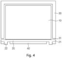
- FIG. 4 is a cross-sectional view taken along line A-A in FIG. 3 .
- a battery module provided in this embodiment includes a cell block 10 provided by stacking a plurality of battery cells, a sub frame 20 having a plate shape, and a main frame 30 welded to be coupled to the sub frame 20.
- the cell block 10 has a rectangular parallelepiped shape with a predetermined thickness as a whole because the cell block 10 is provided by stacking the battery cells, each of which has a thin rectangular parallelepiped shape.
- the cell block 10 is seated on a top surface of the sub frame 10 having the plate shape.
- the sub frame 20 is provided in a rectangular shape having an area that is slightly larger than that of the cell block 10.
- the main frame 30 has a 'U'-shaped cross-sectional shape, of which one side is opened, and three surfaces are closed, and is coupled to the sub frame 20 in a state in which the opened one side faces downward. That is, the main frame 30 is coupled to the sub frame 20 so that the opened side is closed by the sub frame 20.
- the main frame 30 has a flat top surface 30b placed on the cell block 10 and a sidewall surfaces 30a extending to each of both sides of the top surface 30b and bent downward, and the cell block 101 is accommodated in an inner space defined by the main frame 30 and the sub frame 20.
- main frame 30 and the sub frame 20 are welded to be bonded at a point at which the main frame 30 and the sub frame 20 are in contact with each other.
- the sub frame 20 and the main frame 30 are configured to be fitted to match each other so that the sub frame 20 and the main frame 30 are temporarily fixed before the welding is performed.
- a plurality of fitting holes 31 are punched in lower ends of both the sidewall surfaces 30a of the main frame 30 at intervals therebetween at points facing both ends of the sub frame 20, respectively.
- the fitting hole 31 may have a circular or other shapes, but is provided in a rectangular shape (as illustrated in FIG. 2 ) so that the fitting hole 31 is adjustable in vertical, horizontal, and front and rear directions when the welding is performed.
- a protrusion 21 that is insertable into the fitting hole 31 at a point at which the fitting hole 31 is disposed when the main frame 30 enters is disposed on each of both ends (both sides in a longitudinal direction) of the sub frame 20.
- the main frame 30 and the sub frame 20 may be temporarily fixed by inserting the protrusion 21 into the fitting hole 31.
- the support part 22 protrudes downward from both sides of a bottom surface of the sub frame 20 with a gap therebetween.
- the support part 22 has a height that allows an end of the main frame 30 (more precisely, an end of each of the sidewall surfaces of the main frame) to be spaced from the ground when the protrusion 21 enters the fitting hole 31.
- both the sidewall surfaces 30a of the main frame 30 may be in contact with the support part 22, and the welding may be performed at the contact point.
- a cooling part 40 may be coupled to the bottom surface of the sub frame 20 to cool the sub frame 20 and the cell block 10 by exchanging heat with the sub frame 20.
- the prevent invention provides a method for assembling a battery module according to a second embodiment.
- FIG. 5 is a view sequentially illustrating processes of performing an assembly according to a method for assembling a battery module provided in the present invention
- FIG. 6 is an enlarged view of portions at which welding is performed in FIG. 5 .
- a method for assembling a battery module includes a sub frame providing process, a cell block seating process, a temporary assembly process, and a welding process.
- a plate-shaped sub frame 20 is provided, and in the cell block seating process, the cell block 10 is seated on a top surface of the sub frame 20.
- the cell block 10 is disposed at a center so as not to be deviated from a support part 22 protruding from a bottom surface of the sub frame 20 to each of both sides.
- the temporary assembly process of temporarily fixing the main frame 30 to the sub frame 20 is performed in a state in which the cell block 10 is seated on the sub frame 20.
- the main frame 30 is inserted to be slightly spread in a state in which the sidewall surface 30a bent at each of both sides of a top surface 30b is elastically deformed, and when force applied to the sidewall surface 30a is released, as illustrated in ⁇ c> of Fig. 5 , the sidewall surface 30a is elastically restored, and the protrusion 21 of the sub frame 20 is inserted into the fitting hole 31 defined in the main frame 30 and then is temporarily fixed.
- two support parts 22 protrude downward at an interval from each other on the bottom surface of the sub frame 20, and when the protrusion 21 is inserted into the fitting hole 31, the sidewall surface 30a of the main frame 30 is in contact with the support part 22.
- the support part 22 has a height at which a lower end of the sidewall surface 30a of the main frame 30 is spaced apart from the ground.
- a jig pressing process of applying a pressure through a jig 50 so as to allow the main frame 30 and the sub frame 20 to be in close contact with each other so that there is no gap at the point at which the main frame 30 and the sub frame 20 are fitted with each other.
- the jig pressing process is performed before or at the same time as the welding process starts, and the jig 50 applies a pressure to the portion at which the main frame 30 and the sub frame 20 are temporarily fixed to prevent the main frame 30 and the sub frame 20 from being shaken.
- the jig 50 continuously applies a pressure while the welding is in progress to fix the main frame 30 and the sub frame 20.
- the jig pressing process may include a correction process of adjusting a direction in which the pressure of the jig 50 is applied to suppress generation of a height difference between the main frame 30 and the sub frame 20 and twisting of the main frame 30 and the sub frame 20.
- the pressure may be applied so that the welding is performed ( ⁇ II> state) in a state in which the protrusion 21 is in contact with an upper side of the fitting hole 31 ( ⁇ I> state), or the protrusion 21 is in contact with a lower side of the fitting hole 31 according to the position of the main frame 30.
- the jig 50 may be divided into two portions 50a and 50b, which are movable individually, and a space may be defined between the two portions 50a and 50b so that a laser passes therethrough (a through-hole may be defined).
- a through-hole 51 is punched in the jig 50 as a space through which the laser for welding passes so that the welding is performed at the point at which the sidewall surface 30a of the main frame 30 and the support part 22 of the sub frame 20 are in contact with each other. While the jig 50 applies the pressure to the main frame 30 and the sub frame 20, the laser for the welding may be irradiated through the through-hole 51 to perform the welding at the fitted point.
- a cooling part bonding process of bonding a cooling part 40, which cools the sub frame 20 by exchanging heat with the sub frame 20, to the bottom surface of the sub frame 20 may be performed.
- the cooling part 40 may be mounted to be disposed between the two support parts 22.
- the cell block 10 since the cell block 10 is seated on the sub frame 20 having the plate shape, there may be no need to apply an excessive pressure to both the sidewall surfaces 30a of the main frame 30, thereby suppressing an occurrence of the deformation and defects. Thus, since dimensions of the sub frame 20 and the main frame 30 may be stabilized to improve production efficiency.
- the fitting hole 31 is defined in the main frame 30, and the protrusion 21 is disposed on the sub frame 20 so that welding is performed in the state in which the protrusion 21 is temporarily fixed in the fitting hole 31, the welding quality may be improved, and the uniform welding may be achieved.
- the fitting hole 31 and the protrusion 21 may be provided to provide a guide function when the main frame 30 is coupled.
- the support part 22 may be disposed on the sub frame 20 to increase in weldable area, and the main frame 30 may be maintained in close contact with the sub frame 20.
- the support part 22 supports a load instead of the cooling part 40 coupled to the bottom surface of the sub frame 20, the load may be prevented from being applied to the cooling part 40.
- cooling performance of the cooling part 40 may be improved by reducing a thickness of the sub frame 20.
Landscapes
- Chemical & Material Sciences (AREA)
- Engineering & Computer Science (AREA)
- General Chemical & Material Sciences (AREA)
- Electrochemistry (AREA)
- Chemical Kinetics & Catalysis (AREA)
- Physics & Mathematics (AREA)
- Optics & Photonics (AREA)
- Mechanical Engineering (AREA)
- Manufacturing & Machinery (AREA)
- Plasma & Fusion (AREA)
- Inorganic Chemistry (AREA)
- Aviation & Aerospace Engineering (AREA)
- Battery Mounting, Suspending (AREA)
Abstract
Description
- The present application claims the benefit of the priority of
Korean Patent Application No. 10-2022-0067848, filed on June 02, 2022 - The present invention relates to a battery module in which a cell block, in which a plurality of battery cells are stacked (coupled) is mounted in a space in which a sub frame and a main frame are coupled to each other, and a method for assembling the same, and more particularly, to a battery module, which is capable of increasing in cooling efficiency, more easily performing an assembly process and a welding process, and preventing spatter generated during the welding from being introduced therein, and a method for assembling the same.
- A secondary battery having a high energy density is mounted on an electric vehicle (EV) or a hybrid vehicle (HEV) driven by an electric driving source as well as a portable device.
- Such a secondary battery is not only a primary advantage that the use of fossil fuels is significantly reduced, but also an additional advantage that is attracting attention as a new energy source for enhancing environment-friendliness and energy efficiency in that by-products due to the use of energy are not generated at all, and thus, studies on the secondary battery are actively carried out.
- Secondary batteries that are widely used in recent years include lithium ion batteries, lithium polymer batteries, nickel-cadmium batteries, nickel-metal hydride batteries, and nickel-zinc batteries. In addition, the unit battery cell, i.e., an operating voltage of the unit battery cell is about 2.5 V to about 4.2 V.
- Therefore, when a higher output voltage is required, a plurality of individual battery cells are connected to form a secondary battery module, and a plurality of battery modules are assembled to form a battery pack.
- Here, the secondary battery module is configured by gathering cylindrical secondary batteries or by gathering pouch-type secondary batteries.
- Among them, in the battery module constituted by pouch-type secondary batteries, as illustrated in
FIG. 1 that illustrates a longitudinal cross-section of a battery module according to the related art, acell block 1 in which a plurality of battery cells manufactured as pouch-type secondary batteries are stacked by a predetermined number is mounted in aframe 2 having a 'U'-shaped cross-section, and theupper frame 2 has an opened upper side and is disposed to face a bottom surface and both surfaces of thecell block 1. - In addition, a plate-
shaped cover 3 is seated on the opened upper side of theframe 2 to close the opened upper side of theframe 2. Thecover 3 is welded and bonded in a brazing manner in a state of being seated on an upper end of theframe 2. - In addition, a
cooling part 4 in which a coolant is calculated to cool thecell block 1 and the frame is coupled below a bottom surface of theframe 2. - Since the battery module provided with the above configuration according to the related art has to be managed in dimension of flatness and bending angle when the frame is bent in a 'U' shape, there is a problem in that productivity and quality are deteriorated.
- In addition, when the
cell block 1 is mounted, a pressure is applied to theframe 2 to forcibly spread the frame 2 (both wall surfaces) out, but in this process, deformation and/or cracks of theframe 2 may occur. - In addition, when swelling of the battery cells constituting the
cell block 1 occurs, cracks may occur at a brazing portion (welding portion) of theframe 2 and thecover 3. In addition, in order to increase in cooling performance of thecooling part 4, a thickness of theframe 2 has to be minimized at a portion disposed between thecell block 1 and thecooling part 4, but there is a problem in that the thickness is partially reduced due to processing characteristics of theframe 1, which is bent in the 'U' shape. - In addition, as an upper end of the
frame 2 is welded, spatter generated during the welding is introduced into theframe 2, and there is a risk of damaging thecell block 1. - Therefore, a main object of the present invention is to provide a battery module, which is capable of improving cooling efficiency and more easily and reliably performing to improve production efficiency and reduce a defect rate so as to solve problems of the battery module according to the related art (a problem in which a frame is deformed and/or cracked, a problem in which cooling performance of a cooling part is deteriorated due to a thickness of the frame, and a problem spatter is introduced into the inside due to its own weight during welding), and a method for assembling the same.
- A method for assembling a battery module according to the present invention for achieving the above object includes: a sub frame providing process of providing a sub frame having a plate shape; a cell block seating process of seating a cell block (in which a plurality of pouch-type battery cells are stacked), on a top surface of the sub frame; a temporary assembly process of temporarily fixing a main frame having a 'U'-shaped cross-sectional shape, of which one side is opened, and three surfaces are closed, to the sub frame so that the cell block is accommodated into the inside; and a welding process of welding a point at which the main frame and the sub frame are in contact with each other.
- A fitting hole may be punched in the main frame at a point facing each of both ends of the sub frame, and a protrusion that is insertable into the fitting hole may be disposed on each of both the ends of the sub frame, and as the protrusion is inserted into the fitting hole, the main frame and the sub frame may be fitted to match each other so as to be temporarily fixed.
- A support part protruding downward from each of both sides may be disposed on a bottom surface of the sub frame, and when the upper protrusion is inserted into the fitting hole, the main frame may be in contact with the bottom part.
- When the protrusion is fitted into the fitting hole, the support part may have a height at which an end of the main frame is spaced apart from the ground.
- The method may further include a jig pressing process of applying a pressure through a jig to allow the main frame and the sub frame to be in close contact with each other so that there is no gap at a point at which the main frame and the sub frame are fitted into each other, wherein the jig pressing process may be performed before the welding process starts, and while the welding is performed, the jig may be configured to apply a pressure to the portion at which the main frame and the sub frame are temporarily fixed to fix the main frame and the sub frame.
- The jig pressing process may include a correction process of adjusting a direction in which the pressure of the jig is applied to suppress generation of a height difference between the main frame and the sub frame and twisting of the main frame and the sub frame.
- A through-hole through which laser for welding passes may be punched in the jig, and while the jig applies a pressure to the main frame and the sub frame, the laser for welding may be irradiated through the through-hole to weld the fitted point.
- The method may further include a cooling part bonding process of bonding a cooling part configured to cool the sub frame by exchanging heat with the sub frame on a bottom surface of the sub frame.
- Furthermore, the prevent invention additionally provide a battery module that is manufactured through the method for manufacturing the battery module.
- A battery module provided in the present invention includes: a sub frame having a plate shape; a cell block configured by coupling a plurality of battery cells to each other and seated on a top surface of the sub frame; and a main frame having a 'U'-shaped cross-sectional shape of which one side is opened, and three surfaces are closed, coupled to the sub frame so that the opened side is closed by the sub frame, and configured to accommodate the cell block therein, wherein the main frame and the sub frame are bonded and fixed to each other through welding.
- A fitting hole may be punched in the main frame at a point facing each of both ends of the sub frame, and a protrusion that is insertable into the fitting hole may be disposed on each of both the ends of the sub frame, wherein the protrusion may be inserted into the fitting hole.
- A support part protruding downward from each of both sides may be disposed on a bottom surface of the sub frame, and when the protrusion is inserted into the fitting hole, the support part may have a height at which an end of the main frame is spaced apart from the ground.
- The protrusion may be inserted into the fitting hole so that the welding is performed at a point at which the main frame is in contact with the support part.
- The battery module may further include a cooling part coupled to a bottom surface of the sub frame to cool the sub frame.
- In the present invention having the above technical features, since the cell block is seated on the sub frame having the plate shape, there may be no need to apply the excessive pressure to both the sidewall surfaces of the main frame, thereby suppressing the occurrence of the deformation and defects. Thus, since the dimensions of the sub frame and the main frame are stabilized, the production efficiency may be more improved to be optimized.
- Since the fitting hole is defined in the main frame, and the protrusion is disposed on the sub frame so that the main frame and the sub frame are welded in the state in which the protrusion is temporarily fixed in the fitting hole, the welding quality may be improved, and the uniform welding may be achieved. The fitting hole and the protrusion may be provided to provide the guide function when the main frame is coupled.
- In addition, the support part may be disposed on the sub frame to increase in weldable area, and the main frame may be maintained in close contact with the sub frame. In addition, since the support part supports the load instead of the cooling part coupled to the bottom surface of the sub frame, the load may be prevented from being applied to the cooling part.
- In addition, the cooling performance of the cooling part may be improved by reducing the thickness of the sub frame.
- In addition, in the present invention, since the laser welding is performed through the through-hole define in the jig, the spatter generated during the welding may be prevented from being introduced into the inside.
-
-
FIG. 1 is a longitudinal cross-sectional view illustrating a battery module according to a related art. -
FIG. 2 is an exploded perspective view illustrating a state in which a battery module is disassembled according to the present invention. -
FIG. 3 is a perspective view of the battery module according to the present invention. -
FIG. 4 is a cross-sectional view taken along line A-A inFIG. 3 . -
FIG. 5 is a view sequentially illustrating processes of performing an assembly according to a method for assembling a battery module provided in the present invention. -
FIG. 6 is an enlarged view of portions at which welding is performed inFIG. 5 . - Hereinafter, preferred embodiments of the present invention will be described in detail with reference to the accompanying drawings in such a manner that the technical idea of the present invention may easily be carried out by a person with ordinary skill in the art to which the invention pertains. The present invention may, however, be embodied in different forms and should not be construed as limited to the embodiments set forth herein.
- In order to clearly describe the present invention, parts irrelevant to the description are omitted, and the same reference numerals are assigned to the same or similar components throughout the specification.
- Also, terms or words used in this specification and claims should not be restrictively interpreted as ordinary meanings or dictionary-based meanings, but should be interpreted as meanings and concepts conforming to the scope of the present invention on the basis of the principle that an inventor can properly define the concept of a term to describe and explain his or her invention in the best ways.
- The present invention relates to a
cell block 10, in which a battery module in which a plurality of battery cells are coupled (stacked) in a space in which asub frame 20 and amain frame 30 are coupled to each other, is mounted, and a method for assembling the same. Hereinafter, embodiments provided in the prevent invention will be described in more detail with reference to the accompanying drawings. - The prevent invention provides a battery module according to a first embodiment.
-
FIG. 2 is an exploded perspective view illustrating a state in which a battery module is disassembled according to the present invention,FIG. 3 is a perspective view of the battery module according to the present invention, andFIG. 4 is a cross-sectional view taken along line A-A inFIG. 3 . - Referring to the drawings, a battery module provided in this embodiment includes a
cell block 10 provided by stacking a plurality of battery cells, asub frame 20 having a plate shape, and amain frame 30 welded to be coupled to thesub frame 20. - The
cell block 10 has a rectangular parallelepiped shape with a predetermined thickness as a whole because thecell block 10 is provided by stacking the battery cells, each of which has a thin rectangular parallelepiped shape. In addition, thecell block 10 is seated on a top surface of thesub frame 10 having the plate shape. Thesub frame 20 is provided in a rectangular shape having an area that is slightly larger than that of thecell block 10. - The
main frame 30 has a 'U'-shaped cross-sectional shape, of which one side is opened, and three surfaces are closed, and is coupled to thesub frame 20 in a state in which the opened one side faces downward. That is, themain frame 30 is coupled to thesub frame 20 so that the opened side is closed by thesub frame 20. Thus, themain frame 30 has a flattop surface 30b placed on thecell block 10 and a sidewall surfaces 30a extending to each of both sides of thetop surface 30b and bent downward, and the cell block 101 is accommodated in an inner space defined by themain frame 30 and thesub frame 20. - In addition, the
main frame 30 and thesub frame 20 are welded to be bonded at a point at which themain frame 30 and thesub frame 20 are in contact with each other. - In the present invention, the
sub frame 20 and themain frame 30 are configured to be fitted to match each other so that thesub frame 20 and themain frame 30 are temporarily fixed before the welding is performed. - That is, a plurality of
fitting holes 31 are punched in lower ends of both the sidewall surfaces 30a of themain frame 30 at intervals therebetween at points facing both ends of thesub frame 20, respectively. Thefitting hole 31 may have a circular or other shapes, but is provided in a rectangular shape (as illustrated inFIG. 2 ) so that thefitting hole 31 is adjustable in vertical, horizontal, and front and rear directions when the welding is performed. - In addition, a
protrusion 21 that is insertable into thefitting hole 31 at a point at which thefitting hole 31 is disposed when themain frame 30 enters is disposed on each of both ends (both sides in a longitudinal direction) of thesub frame 20. Thus, themain frame 30 and thesub frame 20 may be temporarily fixed by inserting theprotrusion 21 into thefitting hole 31. - In addition, the
support part 22 protrudes downward from both sides of a bottom surface of thesub frame 20 with a gap therebetween. Thesupport part 22 has a height that allows an end of the main frame 30 (more precisely, an end of each of the sidewall surfaces of the main frame) to be spaced from the ground when theprotrusion 21 enters thefitting hole 31. - In addition, when the
protrusion 21 is inserted into thefitting hole 31, both the sidewall surfaces 30a of themain frame 30 may be in contact with thesupport part 22, and the welding may be performed at the contact point. - In addition, a cooling
part 40 may be coupled to the bottom surface of thesub frame 20 to cool thesub frame 20 and thecell block 10 by exchanging heat with thesub frame 20. - The prevent invention provides a method for assembling a battery module according to a second embodiment.
-
FIG. 5 is a view sequentially illustrating processes of performing an assembly according to a method for assembling a battery module provided in the present invention, andFIG. 6 is an enlarged view of portions at which welding is performed inFIG. 5 . - Referring to
FIGS. 5 and6 , a method for assembling a battery module provided in this embodiment includes a sub frame providing process, a cell block seating process, a temporary assembly process, and a welding process. - That is, as illustrated in <a> of
Fig. 5 , in the sub frame providing process, a plate-shapedsub frame 20 is provided, and in the cell block seating process, thecell block 10 is seated on a top surface of thesub frame 20. - Here, the
cell block 10 is disposed at a center so as not to be deviated from asupport part 22 protruding from a bottom surface of thesub frame 20 to each of both sides. - Then, as illustrated in <b> of
Fig. 5 , the temporary assembly process of temporarily fixing themain frame 30 to thesub frame 20 is performed in a state in which thecell block 10 is seated on thesub frame 20. - The
main frame 30 is inserted to be slightly spread in a state in which thesidewall surface 30a bent at each of both sides of atop surface 30b is elastically deformed, and when force applied to thesidewall surface 30a is released, as illustrated in <c> ofFig. 5 , thesidewall surface 30a is elastically restored, and theprotrusion 21 of thesub frame 20 is inserted into thefitting hole 31 defined in themain frame 30 and then is temporarily fixed. - In the state in which the
sub frame 20 and themain frame 30 are temporarily fixed, the point at which themain frame 30 and thesub frame 20 are in contact with each other is welded as illustrated in <d> ofFig. 5 to perform the welding process. - In addition, as described above, two
support parts 22 protrude downward at an interval from each other on the bottom surface of thesub frame 20, and when theprotrusion 21 is inserted into thefitting hole 31, thesidewall surface 30a of themain frame 30 is in contact with thesupport part 22. - Here, when the
protrusion 21 is inserted into thefitting hole 31, as illustrated inFIG. 4 , thesupport part 22 has a height at which a lower end of thesidewall surface 30a of themain frame 30 is spaced apart from the ground. - Before the welding process is performed (or at the same time as the welding process is performed), a jig pressing process of applying a pressure through a
jig 50 so as to allow themain frame 30 and thesub frame 20 to be in close contact with each other so that there is no gap at the point at which themain frame 30 and thesub frame 20 are fitted with each other. - The jig pressing process is performed before or at the same time as the welding process starts, and the
jig 50 applies a pressure to the portion at which themain frame 30 and thesub frame 20 are temporarily fixed to prevent themain frame 30 and thesub frame 20 from being shaken. Thejig 50 continuously applies a pressure while the welding is in progress to fix themain frame 30 and thesub frame 20. - The jig pressing process may include a correction process of adjusting a direction in which the pressure of the
jig 50 is applied to suppress generation of a height difference between themain frame 30 and thesub frame 20 and twisting of themain frame 30 and thesub frame 20. - That is, as illustrated in
FIG. 6 , the pressure may be applied so that the welding is performed (<II> state) in a state in which theprotrusion 21 is in contact with an upper side of the fitting hole 31 (<I> state), or theprotrusion 21 is in contact with a lower side of thefitting hole 31 according to the position of themain frame 30. - However, in both the cases (both the <I> state and the <II> state), it is preferable that the pressure is applied in a lateral direction (left and right direction in the drawing) so that the lowermost end of the
sidewall surface 30a is in close contact with theprotrusion 21. Therefore, thejig 50 may be divided into twoportions portions - That is, a through-
hole 51 is punched in thejig 50 as a space through which the laser for welding passes so that the welding is performed at the point at which thesidewall surface 30a of themain frame 30 and thesupport part 22 of thesub frame 20 are in contact with each other. While thejig 50 applies the pressure to themain frame 30 and thesub frame 20, the laser for the welding may be irradiated through the through-hole 51 to perform the welding at the fitted point. - In addition, a cooling part bonding process of bonding a
cooling part 40, which cools thesub frame 20 by exchanging heat with thesub frame 20, to the bottom surface of thesub frame 20 may be performed. Here, the coolingpart 40 may be mounted to be disposed between the twosupport parts 22. - In the present invention having the above technical features, since the
cell block 10 is seated on thesub frame 20 having the plate shape, there may be no need to apply an excessive pressure to both the sidewall surfaces 30a of themain frame 30, thereby suppressing an occurrence of the deformation and defects. Thus, since dimensions of thesub frame 20 and themain frame 30 may be stabilized to improve production efficiency. - Since the
fitting hole 31 is defined in themain frame 30, and theprotrusion 21 is disposed on thesub frame 20 so that welding is performed in the state in which theprotrusion 21 is temporarily fixed in thefitting hole 31, the welding quality may be improved, and the uniform welding may be achieved. Thefitting hole 31 and theprotrusion 21 may be provided to provide a guide function when themain frame 30 is coupled. - In addition, the
support part 22 may be disposed on thesub frame 20 to increase in weldable area, and themain frame 30 may be maintained in close contact with thesub frame 20. In addition, since thesupport part 22 supports a load instead of the coolingpart 40 coupled to the bottom surface of thesub frame 20, the load may be prevented from being applied to the coolingpart 40. - In addition, cooling performance of the cooling
part 40 may be improved by reducing a thickness of thesub frame 20. - In addition, in the present invention, since the laser welding is performed through the through-
hole 51 define in thejig 50, spatter generated during the welding may be prevented from being introduced into the inside. - While the embodiments of the present invention have been described with reference to the specific embodiments, it will be apparent to those skilled in the art that various changes and modifications may be made without departing from the spirit and scope of the invention as defined in the following claims.
-
- 10:
- Cell block
- 20:
- Sub frame
- 21:
- Protrusion
- 22:
- Support part
- 30:
- Main frame
- 31:
- Fitting hole
- 40:
- Cooling part
Claims (13)
- A method for assembling a battery module, the method comprising:a sub frame providing process of providing a sub frame having a plate shape;a cell block seating process of seating a cell block, in which a plurality of battery cells are coupled to each other, on a top surface of the sub frame;a temporary assembly process of temporarily fixing a main frame having a cross-sectional shape, of which one side is opened, and three surfaces are closed, to the sub frame so that the cell block is accommodated into the inside; anda welding process of welding a point at which the main frame and the sub frame are in contact with each other.
- The method of claim 1, wherein a fitting hole is punched in the main frame at a point facing each of both ends of the sub frame, and a protrusion that is insertable into the fitting hole is disposed on each of both the ends of the sub frame, and
as the protrusion is inserted into the fitting hole, the main frame and the sub frame are fitted to match each other so as to be temporarily fixed. - The method of claim 2, wherein a support part protruding downward from each of both sides is disposed on a bottom surface of the sub frame, and when the upper protrusion is inserted into the fitting hole, the main frame is in contact with the bottom part.
- The method of claim 3, wherein, when the protrusion is fitted into the fitting hole, the support part has a height at which an end of the main frame is spaced apart from the ground.
- The method of claim 1, further comprising a jig pressing process of applying a pressure through a jig to allow the main frame and the sub frame to be in close contact with each other so that there is no gap at a point at which the main frame and the sub frame are fitted into each other,
wherein the jig pressing process is performed before the welding process starts, and while the welding is performed, the jig is configured to apply a pressure to the portion at which the main frame and the sub frame are temporarily fixed to fix the main frame and the sub frame. - The method of claim 5, wherein the jig pressing process comprises a correction process of adjusting a direction in which the pressure of the jig is applied to suppress generation of a height difference between the main frame and the sub frame and twisting of the main frame and the sub frame.
- The method of claim 5, wherein a through-hole through which laser for welding passes is punched in the jig, and while the jig applies a pressure to the main frame and the sub frame, the laser for welding is irradiated through the through-hole to weld the fitted point.
- The method of claim 1, further comprising a cooling part bonding process of bonding a cooling part configured to cool the sub frame by exchanging heat with the sub frame on a bottom surface of the sub frame.
- A battery module comprising:a sub frame having a plate shape;a cell block configured by coupling a plurality of battery cells to each other and seated on a top surface of the sub frame; anda main frame having a cross-sectional shape of which one side is opened, and three surfaces are closed, coupled to the sub frame so that the opened side is closed by the sub frame, and configured to accommodate the cell block therein,wherein the main frame and the sub frame are bonded and fixed to each other through welding.
- The battery module of claim 9, wherein a fitting hole is punched in the main frame at a point facing each of both ends of the sub frame, and a protrusion that is insertable into the fitting hole is disposed on each of both the ends of the sub frame, wherein the protrusion is inserted into the fitting hole.
- The battery module of claim 10, wherein a support part protruding downward from each of both sides is disposed on a bottom surface of the sub frame, and when the protrusion is inserted into the fitting hole, the support part has a height at which an end of the main frame is spaced apart from the ground.
- The battery module of claim 11, wherein the protrusion is inserted into the fitting hole so that the welding is performed at a point at which the main frame is in contact with the support part.
- The battery module of claim 9, further comprising a cooling part coupled to a bottom surface of the sub frame to cool the sub frame.
Applications Claiming Priority (2)
| Application Number | Priority Date | Filing Date | Title |
|---|---|---|---|
| KR1020220067848A KR102874966B1 (en) | 2022-06-02 | 2022-06-02 | Battery module and assembling method thereof |
| PCT/KR2023/006562 WO2023234594A1 (en) | 2022-06-02 | 2023-05-15 | Battery module and assembly method therefor |
Publications (2)
| Publication Number | Publication Date |
|---|---|
| EP4498492A1 true EP4498492A1 (en) | 2025-01-29 |
| EP4498492A4 EP4498492A4 (en) | 2025-06-25 |
Family
ID=89025297
Family Applications (1)
| Application Number | Title | Priority Date | Filing Date |
|---|---|---|---|
| EP23816257.2A Pending EP4498492A4 (en) | 2022-06-02 | 2023-05-15 | BATTERY MODULE AND ITS ASSEMBLY METHOD |
Country Status (6)
| Country | Link |
|---|---|
| US (1) | US20260001165A1 (en) |
| EP (1) | EP4498492A4 (en) |
| JP (1) | JP2025517533A (en) |
| KR (1) | KR102874966B1 (en) |
| CN (1) | CN119137791A (en) |
| WO (1) | WO2023234594A1 (en) |
Family Cites Families (10)
| Publication number | Priority date | Publication date | Assignee | Title |
|---|---|---|---|---|
| JP5968211B2 (en) * | 2012-02-14 | 2016-08-10 | 住友重機械工業株式会社 | Power storage module, manufacturing method thereof, and work machine |
| KR20150005362A (en) * | 2013-07-05 | 2015-01-14 | 주식회사 엘지화학 | Welded Construction For Easy Gas Emission And Battery Module Comprising the Same |
| KR102117848B1 (en) * | 2013-11-13 | 2020-06-02 | 에스케이이노베이션 주식회사 | Battery Module and Manufacturing the Same |
| KR102386201B1 (en) * | 2016-06-17 | 2022-04-12 | 에스케이온 주식회사 | Secondary battery module, and secondary battery pack including the same |
| KR102443098B1 (en) * | 2018-11-12 | 2022-09-13 | 주식회사 엘지에너지솔루션 | Battery module with module housing |
| KR102856548B1 (en) * | 2019-10-22 | 2025-09-08 | 에스케이온 주식회사 | Battery module |
| KR102412402B1 (en) * | 2020-07-21 | 2022-06-23 | 주식회사 포스코 | Joint structure of battery pack frame |
| KR20220043375A (en) * | 2020-09-29 | 2022-04-05 | 에이치그린파워 주식회사 | Battery module and Method for assembling the same |
| JP7232802B2 (en) * | 2020-10-20 | 2023-03-03 | プライムプラネットエナジー&ソリューションズ株式会社 | power storage device |
| KR20220067848A (en) | 2020-11-18 | 2022-05-25 | 주식회사 케이티앤지 | An aerosol generating apparatus and a method for controlling thereof |
-
2022
- 2022-06-02 KR KR1020220067848A patent/KR102874966B1/en active Active
-
2023
- 2023-05-15 EP EP23816257.2A patent/EP4498492A4/en active Pending
- 2023-05-15 US US18/865,046 patent/US20260001165A1/en active Pending
- 2023-05-15 CN CN202380038329.4A patent/CN119137791A/en active Pending
- 2023-05-15 WO PCT/KR2023/006562 patent/WO2023234594A1/en not_active Ceased
- 2023-05-15 JP JP2024569828A patent/JP2025517533A/en active Pending
Also Published As
| Publication number | Publication date |
|---|---|
| EP4498492A4 (en) | 2025-06-25 |
| KR20230167665A (en) | 2023-12-11 |
| KR102874966B1 (en) | 2025-10-22 |
| JP2025517533A (en) | 2025-06-05 |
| CN119137791A (en) | 2024-12-13 |
| WO2023234594A1 (en) | 2023-12-07 |
| US20260001165A1 (en) | 2026-01-01 |
Similar Documents
| Publication | Publication Date | Title |
|---|---|---|
| EP3340365B1 (en) | Battery module including array of cooling fins having different thicknesses | |
| EP2571078B1 (en) | Battery module | |
| EP2130243B1 (en) | Middle or large-sized battery pack case providing improved distribution uniformity in coolant flux | |
| US7989104B2 (en) | Battery module | |
| KR101803958B1 (en) | A Battery Pack Case Having Efficient Cooling Structure | |
| EP2642585B1 (en) | Battery pack having superior cooling efficiency | |
| EP4203156A1 (en) | Battery pack and vehicle including same | |
| EP2642586A2 (en) | Battery pack having superior cooling efficiency | |
| KR20130131658A (en) | Laser welding jig for secondary battery and method of the same | |
| KR100993127B1 (en) | Medium and large battery packs with excellent cooling efficiency | |
| KR20190037922A (en) | Battery Module for Secondary Battery | |
| EP4216339A1 (en) | Battery pack | |
| KR102544785B1 (en) | Battery pack and vehicle comprising the battery pack | |
| EP4462569A1 (en) | Battery pack | |
| EP4376190A1 (en) | Battery pack and vehicle including same | |
| KR20190034736A (en) | Cell module and its manufacturing method | |
| US20260001165A1 (en) | Battery module and method for assembling the same | |
| US20230216130A1 (en) | Secondary battery module and method for manufacturing the same | |
| JP5742800B2 (en) | Partition plate and method for restraining power storage element | |
| US20230307771A1 (en) | Traction battery pack electronics support plate and electronics support method | |
| US20250201991A1 (en) | Battery module, battery pack, vehicle, and battery module manufacturing method | |
| EP4478486A1 (en) | Battery module, and battery module manufacturing method | |
| US20260018722A1 (en) | Battery module | |
| EP4475308A1 (en) | Battery pack and vehicle comprising same | |
| EP4730529A1 (en) | Battery module, and battery pack and vehicle including same |
Legal Events
| Date | Code | Title | Description |
|---|---|---|---|
| STAA | Information on the status of an ep patent application or granted ep patent |
Free format text: STATUS: THE INTERNATIONAL PUBLICATION HAS BEEN MADE |
|
| PUAI | Public reference made under article 153(3) epc to a published international application that has entered the european phase |
Free format text: ORIGINAL CODE: 0009012 |
|
| STAA | Information on the status of an ep patent application or granted ep patent |
Free format text: STATUS: REQUEST FOR EXAMINATION WAS MADE |
|
| 17P | Request for examination filed |
Effective date: 20241023 |
|
| AK | Designated contracting states |
Kind code of ref document: A1 Designated state(s): AL AT BE BG CH CY CZ DE DK EE ES FI FR GB GR HR HU IE IS IT LI LT LU LV MC ME MK MT NL NO PL PT RO RS SE SI SK SM TR |
|
| A4 | Supplementary search report drawn up and despatched |
Effective date: 20250526 |
|
| RIC1 | Information provided on ipc code assigned before grant |
Ipc: H01M 50/276 20210101ALI20250520BHEP Ipc: H01M 50/271 20210101ALI20250520BHEP Ipc: H01M 50/204 20210101ALI20250520BHEP Ipc: B23K 37/04 20060101ALI20250520BHEP Ipc: B23K 26/70 20140101ALI20250520BHEP Ipc: H01M 50/249 20210101ALI20250520BHEP Ipc: H01M 50/224 20210101ALI20250520BHEP Ipc: B23K 101/36 20060101ALI20250520BHEP Ipc: B23K 26/21 20140101ALI20250520BHEP Ipc: B23K 26/382 20140101ALI20250520BHEP Ipc: H01M 10/655 20140101ALI20250520BHEP Ipc: H01M 10/613 20140101ALI20250520BHEP Ipc: H01M 50/211 20210101AFI20250520BHEP |
|
| DAV | Request for validation of the european patent (deleted) | ||
| DAX | Request for extension of the european patent (deleted) | ||
| STAA | Information on the status of an ep patent application or granted ep patent |
Free format text: STATUS: EXAMINATION IS IN PROGRESS |
|
| 17Q | First examination report despatched |
Effective date: 20260105 |