EP4498478A1 - Battery pack - Google Patents
Battery pack Download PDFInfo
- Publication number
- EP4498478A1 EP4498478A1 EP24190240.2A EP24190240A EP4498478A1 EP 4498478 A1 EP4498478 A1 EP 4498478A1 EP 24190240 A EP24190240 A EP 24190240A EP 4498478 A1 EP4498478 A1 EP 4498478A1
- Authority
- EP
- European Patent Office
- Prior art keywords
- fire extinguishing
- smoke
- battery
- battery cells
- battery pack
- Prior art date
- Legal status (The legal status is an assumption and is not a legal conclusion. Google has not performed a legal analysis and makes no representation as to the accuracy of the status listed.)
- Pending
Links
Images


Classifications
-
- H—ELECTRICITY
- H01—ELECTRIC ELEMENTS
- H01M—PROCESSES OR MEANS, e.g. BATTERIES, FOR THE DIRECT CONVERSION OF CHEMICAL ENERGY INTO ELECTRICAL ENERGY
- H01M10/00—Secondary cells; Manufacture thereof
- H01M10/42—Methods or arrangements for servicing or maintenance of secondary cells or secondary half-cells
- H01M10/48—Accumulators combined with arrangements for measuring, testing or indicating the condition of cells, e.g. the level or density of the electrolyte
- H01M10/488—Cells or batteries combined with indicating means for external visualization of the condition, e.g. by change of colour or of light density
-
- A—HUMAN NECESSITIES
- A62—LIFE-SAVING; FIRE-FIGHTING
- A62C—FIRE-FIGHTING
- A62C3/00—Fire prevention, containment or extinguishing specially adapted for particular objects or places
- A62C3/16—Fire prevention, containment or extinguishing specially adapted for particular objects or places in electrical installations, e.g. cableways
-
- A—HUMAN NECESSITIES
- A62—LIFE-SAVING; FIRE-FIGHTING
- A62C—FIRE-FIGHTING
- A62C31/00—Delivery of fire-extinguishing material
-
- A—HUMAN NECESSITIES
- A62—LIFE-SAVING; FIRE-FIGHTING
- A62C—FIRE-FIGHTING
- A62C35/00—Permanently-installed equipment
- A62C35/02—Permanently-installed equipment with containers for delivering the extinguishing substance
- A62C35/11—Permanently-installed equipment with containers for delivering the extinguishing substance controlled by a signal from the danger zone
- A62C35/13—Permanently-installed equipment with containers for delivering the extinguishing substance controlled by a signal from the danger zone with a finite supply of extinguishing material
-
- A—HUMAN NECESSITIES
- A62—LIFE-SAVING; FIRE-FIGHTING
- A62C—FIRE-FIGHTING
- A62C37/00—Control of fire-fighting equipment
- A62C37/08—Control of fire-fighting equipment comprising an outlet device containing a sensor, or itself being the sensor, i.e. self-contained sprinklers
-
- A—HUMAN NECESSITIES
- A62—LIFE-SAVING; FIRE-FIGHTING
- A62C—FIRE-FIGHTING
- A62C99/00—Subject matter not provided for in other groups of this subclass
- A62C99/0009—Methods of extinguishing or preventing the spread of fire by cooling down or suffocating the flames
- A62C99/0072—Methods of extinguishing or preventing the spread of fire by cooling down or suffocating the flames using sprayed or atomised water
-
- A—HUMAN NECESSITIES
- A62—LIFE-SAVING; FIRE-FIGHTING
- A62D—CHEMICAL MEANS FOR EXTINGUISHING FIRES OR FOR COMBATING OR PROTECTING AGAINST HARMFUL CHEMICAL AGENTS; CHEMICAL MATERIALS FOR USE IN BREATHING APPARATUS
- A62D1/00—Fire-extinguishing compositions; Use of chemical substances in extinguishing fires
- A62D1/0028—Liquid extinguishing substances
-
- H—ELECTRICITY
- H01—ELECTRIC ELEMENTS
- H01M—PROCESSES OR MEANS, e.g. BATTERIES, FOR THE DIRECT CONVERSION OF CHEMICAL ENERGY INTO ELECTRICAL ENERGY
- H01M10/00—Secondary cells; Manufacture thereof
- H01M10/42—Methods or arrangements for servicing or maintenance of secondary cells or secondary half-cells
- H01M10/4207—Methods or arrangements for servicing or maintenance of secondary cells or secondary half-cells for several batteries or cells simultaneously or sequentially
-
- H—ELECTRICITY
- H01—ELECTRIC ELEMENTS
- H01M—PROCESSES OR MEANS, e.g. BATTERIES, FOR THE DIRECT CONVERSION OF CHEMICAL ENERGY INTO ELECTRICAL ENERGY
- H01M10/00—Secondary cells; Manufacture thereof
- H01M10/42—Methods or arrangements for servicing or maintenance of secondary cells or secondary half-cells
- H01M10/48—Accumulators combined with arrangements for measuring, testing or indicating the condition of cells, e.g. the level or density of the electrolyte
- H01M10/482—Accumulators combined with arrangements for measuring, testing or indicating the condition of cells, e.g. the level or density of the electrolyte for several batteries or cells simultaneously or sequentially
-
- H—ELECTRICITY
- H01—ELECTRIC ELEMENTS
- H01M—PROCESSES OR MEANS, e.g. BATTERIES, FOR THE DIRECT CONVERSION OF CHEMICAL ENERGY INTO ELECTRICAL ENERGY
- H01M10/00—Secondary cells; Manufacture thereof
- H01M10/42—Methods or arrangements for servicing or maintenance of secondary cells or secondary half-cells
- H01M10/48—Accumulators combined with arrangements for measuring, testing or indicating the condition of cells, e.g. the level or density of the electrolyte
- H01M10/486—Accumulators combined with arrangements for measuring, testing or indicating the condition of cells, e.g. the level or density of the electrolyte for measuring temperature
-
- H—ELECTRICITY
- H01—ELECTRIC ELEMENTS
- H01M—PROCESSES OR MEANS, e.g. BATTERIES, FOR THE DIRECT CONVERSION OF CHEMICAL ENERGY INTO ELECTRICAL ENERGY
- H01M10/00—Secondary cells; Manufacture thereof
- H01M10/60—Heating or cooling; Temperature control
- H01M10/62—Heating or cooling; Temperature control specially adapted for specific applications
- H01M10/625—Vehicles
-
- H—ELECTRICITY
- H01—ELECTRIC ELEMENTS
- H01M—PROCESSES OR MEANS, e.g. BATTERIES, FOR THE DIRECT CONVERSION OF CHEMICAL ENERGY INTO ELECTRICAL ENERGY
- H01M50/00—Constructional details or processes of manufacture of the non-active parts of electrochemical cells other than fuel cells, e.g. hybrid cells
- H01M50/20—Mountings; Secondary casings or frames; Racks, modules or packs; Suspension devices; Shock absorbers; Transport or carrying devices; Holders
- H01M50/204—Racks, modules or packs for multiple batteries or multiple cells
- H01M50/207—Racks, modules or packs for multiple batteries or multiple cells characterised by their shape
- H01M50/209—Racks, modules or packs for multiple batteries or multiple cells characterised by their shape adapted for prismatic or rectangular cells
-
- H—ELECTRICITY
- H01—ELECTRIC ELEMENTS
- H01M—PROCESSES OR MEANS, e.g. BATTERIES, FOR THE DIRECT CONVERSION OF CHEMICAL ENERGY INTO ELECTRICAL ENERGY
- H01M50/00—Constructional details or processes of manufacture of the non-active parts of electrochemical cells other than fuel cells, e.g. hybrid cells
- H01M50/20—Mountings; Secondary casings or frames; Racks, modules or packs; Suspension devices; Shock absorbers; Transport or carrying devices; Holders
- H01M50/204—Racks, modules or packs for multiple batteries or multiple cells
- H01M50/207—Racks, modules or packs for multiple batteries or multiple cells characterised by their shape
- H01M50/213—Racks, modules or packs for multiple batteries or multiple cells characterised by their shape adapted for cells having curved cross-section, e.g. round or elliptic
-
- H—ELECTRICITY
- H01—ELECTRIC ELEMENTS
- H01M—PROCESSES OR MEANS, e.g. BATTERIES, FOR THE DIRECT CONVERSION OF CHEMICAL ENERGY INTO ELECTRICAL ENERGY
- H01M50/00—Constructional details or processes of manufacture of the non-active parts of electrochemical cells other than fuel cells, e.g. hybrid cells
- H01M50/20—Mountings; Secondary casings or frames; Racks, modules or packs; Suspension devices; Shock absorbers; Transport or carrying devices; Holders
- H01M50/249—Mountings; Secondary casings or frames; Racks, modules or packs; Suspension devices; Shock absorbers; Transport or carrying devices; Holders specially adapted for aircraft or vehicles, e.g. cars or trains
-
- H—ELECTRICITY
- H01—ELECTRIC ELEMENTS
- H01M—PROCESSES OR MEANS, e.g. BATTERIES, FOR THE DIRECT CONVERSION OF CHEMICAL ENERGY INTO ELECTRICAL ENERGY
- H01M50/00—Constructional details or processes of manufacture of the non-active parts of electrochemical cells other than fuel cells, e.g. hybrid cells
- H01M50/20—Mountings; Secondary casings or frames; Racks, modules or packs; Suspension devices; Shock absorbers; Transport or carrying devices; Holders
- H01M50/258—Modular batteries; Casings provided with means for assembling
-
- H—ELECTRICITY
- H01—ELECTRIC ELEMENTS
- H01M—PROCESSES OR MEANS, e.g. BATTERIES, FOR THE DIRECT CONVERSION OF CHEMICAL ENERGY INTO ELECTRICAL ENERGY
- H01M50/00—Constructional details or processes of manufacture of the non-active parts of electrochemical cells other than fuel cells, e.g. hybrid cells
- H01M50/30—Arrangements for facilitating escape of gases
-
- H—ELECTRICITY
- H01—ELECTRIC ELEMENTS
- H01M—PROCESSES OR MEANS, e.g. BATTERIES, FOR THE DIRECT CONVERSION OF CHEMICAL ENERGY INTO ELECTRICAL ENERGY
- H01M50/00—Constructional details or processes of manufacture of the non-active parts of electrochemical cells other than fuel cells, e.g. hybrid cells
- H01M50/30—Arrangements for facilitating escape of gases
- H01M50/308—Detachable arrangements, e.g. detachable vent plugs or plug systems
-
- H—ELECTRICITY
- H01—ELECTRIC ELEMENTS
- H01M—PROCESSES OR MEANS, e.g. BATTERIES, FOR THE DIRECT CONVERSION OF CHEMICAL ENERGY INTO ELECTRICAL ENERGY
- H01M50/00—Constructional details or processes of manufacture of the non-active parts of electrochemical cells other than fuel cells, e.g. hybrid cells
- H01M50/30—Arrangements for facilitating escape of gases
- H01M50/342—Non-re-sealable arrangements
- H01M50/3425—Non-re-sealable arrangements in the form of rupturable membranes or weakened parts, e.g. pierced with the aid of a sharp member
-
- H—ELECTRICITY
- H01—ELECTRIC ELEMENTS
- H01M—PROCESSES OR MEANS, e.g. BATTERIES, FOR THE DIRECT CONVERSION OF CHEMICAL ENERGY INTO ELECTRICAL ENERGY
- H01M50/00—Constructional details or processes of manufacture of the non-active parts of electrochemical cells other than fuel cells, e.g. hybrid cells
- H01M50/30—Arrangements for facilitating escape of gases
- H01M50/375—Vent means sensitive to or responsive to temperature
-
- H—ELECTRICITY
- H01—ELECTRIC ELEMENTS
- H01M—PROCESSES OR MEANS, e.g. BATTERIES, FOR THE DIRECT CONVERSION OF CHEMICAL ENERGY INTO ELECTRICAL ENERGY
- H01M50/00—Constructional details or processes of manufacture of the non-active parts of electrochemical cells other than fuel cells, e.g. hybrid cells
- H01M50/30—Arrangements for facilitating escape of gases
- H01M50/383—Flame arresting or ignition-preventing means
-
- H—ELECTRICITY
- H01—ELECTRIC ELEMENTS
- H01M—PROCESSES OR MEANS, e.g. BATTERIES, FOR THE DIRECT CONVERSION OF CHEMICAL ENERGY INTO ELECTRICAL ENERGY
- H01M10/00—Secondary cells; Manufacture thereof
- H01M10/60—Heating or cooling; Temperature control
- H01M10/61—Types of temperature control
- H01M10/613—Cooling or keeping cold
-
- H—ELECTRICITY
- H01—ELECTRIC ELEMENTS
- H01M—PROCESSES OR MEANS, e.g. BATTERIES, FOR THE DIRECT CONVERSION OF CHEMICAL ENERGY INTO ELECTRICAL ENERGY
- H01M2200/00—Safety devices for primary or secondary batteries
- H01M2200/10—Temperature sensitive devices
-
- H—ELECTRICITY
- H01—ELECTRIC ELEMENTS
- H01M—PROCESSES OR MEANS, e.g. BATTERIES, FOR THE DIRECT CONVERSION OF CHEMICAL ENERGY INTO ELECTRICAL ENERGY
- H01M2220/00—Batteries for particular applications
- H01M2220/20—Batteries in motive systems, e.g. vehicle, ship, plane
-
- Y—GENERAL TAGGING OF NEW TECHNOLOGICAL DEVELOPMENTS; GENERAL TAGGING OF CROSS-SECTIONAL TECHNOLOGIES SPANNING OVER SEVERAL SECTIONS OF THE IPC; TECHNICAL SUBJECTS COVERED BY FORMER USPC CROSS-REFERENCE ART COLLECTIONS [XRACs] AND DIGESTS
- Y02—TECHNOLOGIES OR APPLICATIONS FOR MITIGATION OR ADAPTATION AGAINST CLIMATE CHANGE
- Y02E—REDUCTION OF GREENHOUSE GAS [GHG] EMISSIONS, RELATED TO ENERGY GENERATION, TRANSMISSION OR DISTRIBUTION
- Y02E60/00—Enabling technologies; Technologies with a potential or indirect contribution to GHG emissions mitigation
- Y02E60/10—Energy storage using batteries
Definitions
- the present disclosure relates to a battery pack.
- a battery pack may include a plurality of above-mentioned high-power secondary batteries connected in series, and thus the battery pack generally has a high capacity and high power.
- the battery pack may be utilized for driving a motor of a device which requires high power, such as an electric vehicle or the like.
- an increase in temperature of one or more of the secondary batteries can cause a fire, and extinguishing a fire when it occurs presents a challenge due to the characteristics of the battery pack.
- the present disclosure provides a battery pack capable of detecting the ignition of battery cells in advance before ignition and shortening a fire extinguishing time to improve safety.
- a battery pack includes: a battery module including battery cells (e.g. a plurality of battery cells) electrically connected together and including vents (e.g. the plurality of battery cells including a plurality of vents); a smoke generating device configured to generate smoke in response to a temperature of at least one of the battery cells being higher than a reference temperature; a smoke detection device configured to detect the smoke generated from the smoke generating device and to generate an alarm signal in response to detection of the smoke; an agent storage unit including a fire extinguishing tube having one end proximate to the battery module and configured to store a fire extinguishing agent supplied to the fire extinguishing tube; and a fire extinguishing receiver configured to receive the alarm signal from the smoke detection device and to generate a supply signal which causes the fire extinguishing agent in the agent storage unit to be supplied to the fire extinguishing tube.
- battery cells e.g. a plurality of battery cells
- vents e.g. the plurality of battery cells including
- the smoke generated from the smoke generating device may have a color.
- the agent storage unit may be configured to spray the fire extinguishing agent from the fire extinguishing tube onto the battery cells (e.g. the fire extinguishing tube may be configured to spray the fire extinguishing agent on the plurality of battery cells) in response to a fire occurring in the battery pack.
- the smoke generating device may be outside the battery module.
- the battery pack may further include a temperature sensing unit configured to detect the temperature of one or more of the battery cells (e.g. at least one of the plurality of battery cells) and configured to transmit an abnormal signal to the smoke generating device in response to the temperature of one or more of the battery cells being higher than the reference temperature.
- a temperature sensing unit configured to detect the temperature of one or more of the battery cells (e.g. at least one of the plurality of battery cells) and configured to transmit an abnormal signal to the smoke generating device in response to the temperature of one or more of the battery cells being higher than the reference temperature.
- a battery pack includes: a battery module including battery cells (e.g. a plurality of battery cells) electrically connected together and including vents (e.g. the plurality of battery cells including a plurality of vents); a smoke detection device configured to detect an internal gas discharged through at least one of the vents and to generate an alarm signal; an agent storage unit including a fire extinguishing tube having one end proximate to the battery module (e.g. connected to the battery module) and configured to store a fire extinguishing agent supplied to the fire extinguishing tube; and a fire extinguishing receiver configured to receive the alarm signal of the smoke detection device and to generate a supply signal (e.g. in response to the alarm signal) which causes the fire extinguishing agent in the agent storage unit to be supplied to the fire extinguishing tube.
- a battery module including battery cells (e.g. a plurality of battery cells) electrically connected together and including vents (e.g. the plurality of battery cells including a pluralit
- the smoke detection device may include a suction pipe connected to the battery module and configured to suction the internal gas.
- Each of the battery cells may be configured to discharge the internal gas through one of the vents in response to an internal pressure being higher than a reference pressure.
- the agent storage unit may be configured to spray the fire extinguishing agent from the fire extinguishing tube onto the battery cells (e.g. the fire extinguishing tube may be configured to spray the fire extinguishing agent on the plurality of battery cells) in response to a fire occurring in the battery pack.
- first, second, and the like are used in the present specification to describe various members, components, regions, layers and/or parts, it is obvious that these members, components, regions, layers and/or parts should not be limited by these terms. These terms are used only to distinguish one member, component, region, layer, or part from another member, component, region, layer, or part. Accordingly, a first member, component, region, layer, or part to be described later may refer to a second member, component, region, layer, or part without departing from the teachings of the present disclosure.
- a case in which a certain component is electrically connected to another component includes not only a case in which the components are directly connected, but also a case in which the components are connected with another element therebetween.
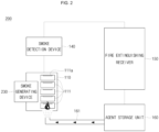
- FIG. 1 is a schematic diagram illustrating a battery pack according to an embodiment of the present disclosure.
- a battery pack 100 may include a battery module 110, a temperature sensing unit 120, a smoke generating device 130, a smoke detection device 140, a fire extinguishing receiver 150, and an agent storage unit 160.
- the battery module 110 includes a plurality of battery cells 111 electrically connected together.
- the plurality of battery cells 111 may be connected in series and/or parallel and may be accommodated in a housing.
- each of the battery cells 111 may be a cylindrical battery cell or prismatic battery cell.
- Each of the battery cells 111 may include an electrode assembly accommodated in a case and a cap plate or cap assembly coupled to an upper portion of the case. Further, each of the battery cells 111 may include a vent 111a configured to be broken in response to an internal gas being generated and to thereby discharge the internal gas.
- the temperature sensing unit 120 may be configured detect a temperature of the battery module 110. In some embodiments, the temperature sensing unit 120 may be configured to detect a temperature of each battery cell 111. In one or more embodiments, the temperature sensing unit 120 may include a temperature sensor installed in each battery cell 111 to measure (e.g., individually measure) the temperature of the battery cells 111. Further, the temperature sensing unit 120 may be configured to detect the temperature of the battery cells 111 and to transmit the temperature information of the battery cells 111 to the smoke generating device 130. The temperature sensing unit 120 may be configured to transmit an abnormal signal to the smoke generating device 130 in response to the temperature of one or more of the battery cells 111 being higher than a reference temperature.
- the reference temperature of the temperature sensing unit 120 may be set to approximately 100 °C, but the present disclosure is not limited thereto.
- the reference temperature set in the temperature sensing unit 120 may be changed or varied according to a variety of design considerations. However, the reference temperature may be set to a temperature lower than the ignition temperature of the battery cells 111. In one or more embodiments, the battery cells 111 may be configured to ignite at approximately 150 °C.
- the smoke generating device 130 may be configured to receive the abnormal signal from the temperature sensing unit 120 and to generate smoke in response to receipt of the abnormal signal. As the temperature of the battery cells 111 increases abnormally, the smoke generating device 130 receives an abnormal signal from the temperature sensing unit 120 and generates smoke, thereby notifying personnel of a dangerous situation.
- the smoke generating device 130 may include a driving circuit configured to operate in response to receiving the abnormal signal from the temperature sensing unit 120. In some embodiments, in response to the smoke generating device 130 receiving the abnormal signal from the temperature sensing unit 120, the driving circuit of the smoke generating device 130 operates and internal chemicals react with each other, thereby generating smoke.
- the smoke generated from the smoke generating device 130 may have a color, such as red or blue, which makes it easy to identify the smoke from the outside.
- the smoke generating device 130 may be on an outer surface of the battery module 110, for example, in the housing where the battery cells 111 are accommodated. Before a fire occurs in the battery module 110, the smoke generating device 130 may serve to prevent the fire by receiving 111 from the temperature sensing unit 120 an abnormal signal indicating an abnormal temperature rise of the battery cells and thereby generating smoke to notify personnel, and at the same time, notifying the fire extinguishing receiver 150 through the smoke detection device 140.
- the smoke generated from the smoke generating device 130 may be sufficient to be detected by the smoke detection device 140 and may contain ingredients which are harmless to the human body.
- the smoke detection device 140 is configured to detect the smoke generated from the smoke generating device 130.
- the smoke detection device 140 is configured to detect the smoke from the smoke generating device 130 and to transmit an alarm signal which indicates the generation of smoke to the fire extinguishing receiver 150.
- the smoke detection device 140 may be adjacent to the smoke generating device 130.
- the smoke detection device 140 may be on a ceiling of a facility in which the battery module 110 is installed.
- the smoke detection device 140 may be configured to detect not only the smoke generated from the smoke generating device 130 but also the smoke generated from a fire occurring in the battery module 110.
- the fire extinguishing receiver 150 is configured to receive the alarm signal from the smoke detection device 140 and to transmit a supply signal which causes a fire extinguishing agent to be supplied from (e.g., discharged from) the agent storage unit 160. Because the temperature of the battery module 110 rises and there is a risk of fire (or ignition) through the smoke detection device 140, the fire extinguishing receiver 150 may be configured to issue a command that the fire extinguishing agent be supplied from (e.g., discharged from) the agent storage unit 160 so that the fire can be quickly extinguished.
- the agent storage unit 160 stores (e.g. is configured to store) the fire extinguishing agent therein.
- the agent storage unit 160 includes a fire extinguishing tube 161 configured to supply the fire extinguishing agent to the battery module 110.
- a length of the fire extinguishing tube 161 may be roughly (approximately) 50 meters (m), but the present disclosure is not limited thereto.
- the length of the fire extinguishing tube 161 may be changed according to the installation position of the battery module 110 and/or the agent storage unit 160.
- the fire extinguishing agent may contain one or more substances capable of extinguishing a fire occurring in the battery module 110.
- the fire extinguishing agent may contain one or more of argon, nitrogen, or carbon dioxide, but the present disclosure is not limited thereto. Any type or kind of fire extinguishing agent capable of extinguishing a fire may be utilized.
- the agent storage unit 160 supplies (e.g., discharges) the fire extinguishing agent to the fire extinguishing tube 161 in response to receiving the supply signal which causes the fire extinguishing agent to be supplied from the fire extinguishing receiver 150, the fire extinguishing agent may be filled in the fire extinguishing tube 161 in advance before a fire occurs in the battery module 110.
- the fire extinguishing agent filled in the fire extinguishing tube 161 may be directly sprayed on the battery module 110 to extinguish the fire in the battery module 110 in response to a fire occurring in the battery module 110, and thus a fire suppressing time (or fire extinguishing time) may be shortened compared to an embodiment in which the fire extinguishing tube 161 is not pre-filled with the fire extinguishing agent.
- the length of the fire extinguishing tube 161 is approximately 50 m, it may take approximately 20 to approximately 30 seconds after a fire for the smoke detection device 140 to detect the smoke and transmit an alarm signal to the fire extinguishing receiver 150, the fire extinguishing receiver 150 to transmit a signal for supplying the fire extinguishing agent to the agent storage unit 160, and the fire extinguishing agent to be sprayed on the battery module 110.
- the fire extinguishing agent may spread and cause a large fire. Accordingly, even when the extinguishing agent is supplied from the agent storage unit 160, the fire may not be extinguished or the fire extinguishing time may be too long.
- the fire extinguishing agent may be supplied and filled in the fire extinguishing tube 161 in advance (i.e., pre-filled) based on operation of the smoke generating device 130 before a fire occurs in the battery module 110, when a fire occurs, the fire extinguishing agent may be immediately (or substantially immediately) sprayed on the battery module 110 to shorten the fire extinguishing time and prevent the fire from spreading. Further, the present disclosure may prevent a fire more effectively as a distance between the battery module 110 and the agent storage unit 160 increases.
- the fire extinguishing agent accommodated in the fire extinguishing tube 161 may be sprayed while a portion of the fire extinguishing tube 161 melts due to a fire occurring in the battery module 110.
- the fire extinguishing tube 161 may surround (or surround at least a portion of) the battery module 110.
- the agent storage unit 160 may supply the fire extinguishing agent to the fire extinguishing tube 161 in response to receiving the supply signal which causes the fire extinguishing agent to be supplied from the fire extinguishing receiver 150, and the fire extinguishing agent supplied to the fire extinguishing tube 161 may be immediately (or substantially immediately) sprayed on the battery cells 111.
- the battery cells 111 may be cooled by spraying the fire extinguishing agent on the battery cells 111 before a fire occurs in the battery module 110.
- FIG. 2 is a schematic configuration diagram illustrating a battery pack 200 according to another embodiment of the present disclosure.
- a battery pack 200 may include a battery module 110, a smoke generating device 230, a smoke detection device 140, a fire extinguishing receiver 150, and an agent storage unit 160.
- the smoke generating device 230 may be in the battery module 110. In some embodiments, the smoke generating device 230 may be on or attached to a surface of each battery cell 111 in the battery module 110.
- the smoke generating device 230 may be a sheet and may accommodate or include chemicals configured to cause a chemical reaction and generate smoke in response to a reference temperature being reached in the battery module 110. In one or more embodiments, the reference temperature may be set to approximately 100° C, but the present disclosure is not limited thereto. The reference temperature set in the smoke generating device 230 may be changed or varied according to a variety of design considerations.
- the smoke generating device 230 may be configured to prevent a fire by generating smoke that is visible by personnel and also notifying the fire extinguishing receiver 150 through the smoke detection device 140 in response to a temperature of one or more of the battery cells 111 increasing to the reference temperature or higher.
- FIG. 3 is a schematic configuration diagram illustrating a battery pack 300 according to still another embodiment of the present disclosure.
- a battery pack 300 may include a battery module 110, a smoke detection device 340, a fire extinguishing receiver 150, and an agent storage unit 160.
- the smoke detection device 340 may include a suction pipe 341 connected to the battery module 110.
- the suction pipe 341 may be configured to suction an internal gas generated from the battery cells 111 in the battery module 110.
- the smoke detection device 340 may be configured to detect the internal gas generated from the battery cells 111 through the suction pipe 341.
- the vent 111a in one or more of the battery cells 111 is broken and the internal gas may be discharged to the outside of the battery cells 111.
- the smoke detection device 340 may be configured to detect the internal gas discharged from one or more of the battery cells 111 through the suction pipe 341 and to transmit an alarm signal which notifies the generation of gas to the fire extinguishing receiver 150.
- the smoke detection device 340 may be configured to supply and fill a fire extinguishing agent in the fire extinguishing tube 161 in advance (i.e., prior to a fire) in response to detecting the internal gas generated from one or more of the battery cells 111 and notifying the fire extinguishing receiver 150 before a fire occurs in the battery module 110, when a fire occurs, the fire extinguishing agent may be immediately (or substantially immediately) sprayed on the battery module 110 to shorten the fire extinguishing time and prevent the fire from spreading.
- a fire extinguishing agent can be sprayed on battery cells immediately (or substantially immediately) to shorten a fire extinguishing time and prevent a fire from spreading in response to a fire occurring by detecting a temperature rise of the battery cells before the fire occurs in a battery module and by supplying the fire extinguishing agent to the inside of a fire extinguishing tube in advance (i.e., prior to the fire) based on the operation of a smoke generating device.
- a dangerous state or condition of the battery cells can be signaled to personnel to prevent causalities by including the smoke generating device which detects the temperature of the battery cells to generate smoke before a fire occurs in the battery module.
Landscapes
- Chemical Kinetics & Catalysis (AREA)
- General Chemical & Material Sciences (AREA)
- Chemical & Material Sciences (AREA)
- Electrochemistry (AREA)
- Engineering & Computer Science (AREA)
- Manufacturing & Machinery (AREA)
- Emergency Management (AREA)
- Business, Economics & Management (AREA)
- Public Health (AREA)
- Health & Medical Sciences (AREA)
- Aviation & Aerospace Engineering (AREA)
- Battery Mounting, Suspending (AREA)
- Gas Exhaust Devices For Batteries (AREA)
Abstract
A battery pack capable of detecting the ignition of battery cells before ignition and thereby shortening a fire extinguishing time to improve safety. The battery pack includes a battery module having battery cells electrically connected and including vents; a smoke generating device configured to generate smoke in response to a temperature of the battery cells being higher than a reference temperature; a smoke detection device configured to detect the smoke generated from the smoke generating device and to generate an alarm signal; an agent storage unit including a fire extinguishing tube connected to the battery module and configured to store a fire extinguishing agent supplied to the fire extinguishing tube; and a fire extinguishing receiver configured to receive the alarm signal of the smoke detection device and to generate a supply signal causing the fire extinguishing agent in the agent storage unit to be supplied to the fire extinguishing tube.
Description
- The present disclosure relates to a battery pack.
- Recently, high-power secondary batteries using non-aqueous electrolytes with high energy density have been developed. A battery pack may include a plurality of above-mentioned high-power secondary batteries connected in series, and thus the battery pack generally has a high capacity and high power. The battery pack may be utilized for driving a motor of a device which requires high power, such as an electric vehicle or the like.
- In the battery pack, because several to dozens of battery cells may be connected to form one battery pack, the heat generated from each battery cell needs to be dissipated, and temperature management of the secondary battery can be of utmost importance. Thus, technology for improving safety is being researched.
- Further, an increase in temperature of one or more of the secondary batteries can cause a fire, and extinguishing a fire when it occurs presents a challenge due to the characteristics of the battery pack.
- The above-described information disclosed in the background technology of the present disclosure is only for improving understanding of the background of the present disclosure, and therefore may include information that does not constitute the related art.
- The present disclosure provides a battery pack capable of detecting the ignition of battery cells in advance before ignition and shortening a fire extinguishing time to improve safety.
- A battery pack according to one embodiment of the present disclosure includes: a battery module including battery cells (e.g. a plurality of battery cells) electrically connected together and including vents (e.g. the plurality of battery cells including a plurality of vents); a smoke generating device configured to generate smoke in response to a temperature of at least one of the battery cells being higher than a reference temperature; a smoke detection device configured to detect the smoke generated from the smoke generating device and to generate an alarm signal in response to detection of the smoke; an agent storage unit including a fire extinguishing tube having one end proximate to the battery module and configured to store a fire extinguishing agent supplied to the fire extinguishing tube; and a fire extinguishing receiver configured to receive the alarm signal from the smoke detection device and to generate a supply signal which causes the fire extinguishing agent in the agent storage unit to be supplied to the fire extinguishing tube.
- The smoke generated from the smoke generating device may have a color.
- The agent storage unit may be configured to spray the fire extinguishing agent from the fire extinguishing tube onto the battery cells (e.g. the fire extinguishing tube may be configured to spray the fire extinguishing agent on the plurality of battery cells) in response to a fire occurring in the battery pack.
- The smoke generating device may be outside the battery module.
- The battery pack may further include a temperature sensing unit configured to detect the temperature of one or more of the battery cells (e.g. at least one of the plurality of battery cells) and configured to transmit an abnormal signal to the smoke generating device in response to the temperature of one or more of the battery cells being higher than the reference temperature.
- The smoke generating device may be a sheet attached to a surface of each of the battery cells.
- A battery pack according to another embodiment of the present disclosure includes: a battery module including battery cells (e.g. a plurality of battery cells) electrically connected together and including vents (e.g. the plurality of battery cells including a plurality of vents); a smoke detection device configured to detect an internal gas discharged through at least one of the vents and to generate an alarm signal; an agent storage unit including a fire extinguishing tube having one end proximate to the battery module (e.g. connected to the battery module) and configured to store a fire extinguishing agent supplied to the fire extinguishing tube; and a fire extinguishing receiver configured to receive the alarm signal of the smoke detection device and to generate a supply signal (e.g. in response to the alarm signal) which causes the fire extinguishing agent in the agent storage unit to be supplied to the fire extinguishing tube.
- The smoke detection device may include a suction pipe connected to the battery module and configured to suction the internal gas.
- Each of the battery cells may be configured to discharge the internal gas through one of the vents in response to an internal pressure being higher than a reference pressure.
- The agent storage unit may be configured to spray the fire extinguishing agent from the fire extinguishing tube onto the battery cells (e.g. the fire extinguishing tube may be configured to spray the fire extinguishing agent on the plurality of battery cells) in response to a fire occurring in the battery pack.
- At least some of the above and other features of the invention are set out in the claims.
-
-
FIG. 1 is a schematic diagram illustrating a battery pack according to an embodiment of the present disclosure. -
FIG. 2 is a schematic diagram illustrating a battery pack according to another embodiment of the present disclosure. -
FIG. 3 is a schematic diagram illustrating a battery pack according to a further embodiment of the present disclosure. - Hereinafter, preferred embodiments of the present disclosure will be described in detail with reference to the accompanying drawings.
- The embodiments of the present disclosure are provided to more completely describe the present disclosure to those skilled in the art, the following embodiments may be modified into various other forms, and the scope of the present disclosure is not limited to the following embodiments. Rather, these embodiments are provided to make the present disclosure more meaningful and complete and to fully convey the present disclosure to those skilled in the art.
- Further, in the following drawings, the thickness and size of each layer are exaggerated for convenience and clarity of description, and the same reference numerals indicate the same elements in the drawings. As used in the present specification, the term "and/or" includes any one of and all combinations of one or more of the listed items. Further, the meaning of "being connected" in the present specification refers to not only a case in which member A and member B are directly connected, but also a case in which member C is interposed between member A and member B to indirectly connect member A and member B.
- The terms used in the present specification are used to describe specific embodiments and are not intended to limit the present disclosure. As used in the present specification, a singular form may include a plural form unless the context clearly indicates otherwise. Further, when used in the present specification, "comprise" and/or "comprising" specify(ies) the presence of mentioned features, numbers, steps, operations, members, elements and/or groups thereof, and do(es) not exclude the presence or addition of one or more other features, numbers, steps, operations, members, elements and/or groups.
- Although the terms first, second, and the like are used in the present specification to describe various members, components, regions, layers and/or parts, it is obvious that these members, components, regions, layers and/or parts should not be limited by these terms. These terms are used only to distinguish one member, component, region, layer, or part from another member, component, region, layer, or part. Accordingly, a first member, component, region, layer, or part to be described later may refer to a second member, component, region, layer, or part without departing from the teachings of the present disclosure.
- Spatially-related terms such as "beneath," "below," "lower," "above," and "upper" are used for easy understanding of one element or feature and another element or feature shown in the drawings. These spatially-related terms are provided for easy understanding of the present disclosure according to various process states or usage states of the present disclosure, and are not intended to limit the present disclosure. For example, when the elements or features in the drawings are reversed, an element described as "lower" or "below" "becomes "upper" or "above." Accordingly, "below" is a concept encompassing "above" or "below."
- Preferred embodiments of the present disclosure will be described in detail with reference to the accompanying drawings as follows so that those skilled in the art may easily carry out the present disclosure.
- Here, the same reference numerals are added to components having similar configurations and operations throughout the specification. Further, a case in which a certain component is electrically connected to another component includes not only a case in which the components are directly connected, but also a case in which the components are connected with another element therebetween.
-
FIG. 1 is a schematic diagram illustrating a battery pack according to an embodiment of the present disclosure. - Referring to
FIG. 1 , abattery pack 100 according to one embodiment of the present disclosure may include abattery module 110, atemperature sensing unit 120, asmoke generating device 130, asmoke detection device 140, afire extinguishing receiver 150, and anagent storage unit 160. - The
battery module 110 includes a plurality ofbattery cells 111 electrically connected together. In some embodiments, the plurality ofbattery cells 111 may be connected in series and/or parallel and may be accommodated in a housing. In one or more embodiments, each of thebattery cells 111 may be a cylindrical battery cell or prismatic battery cell. Each of thebattery cells 111 may include an electrode assembly accommodated in a case and a cap plate or cap assembly coupled to an upper portion of the case. Further, each of thebattery cells 111 may include avent 111a configured to be broken in response to an internal gas being generated and to thereby discharge the internal gas. - The
temperature sensing unit 120 may be configured detect a temperature of thebattery module 110. In some embodiments, thetemperature sensing unit 120 may be configured to detect a temperature of eachbattery cell 111. In one or more embodiments, thetemperature sensing unit 120 may include a temperature sensor installed in eachbattery cell 111 to measure (e.g., individually measure) the temperature of thebattery cells 111. Further, thetemperature sensing unit 120 may be configured to detect the temperature of thebattery cells 111 and to transmit the temperature information of thebattery cells 111 to thesmoke generating device 130. Thetemperature sensing unit 120 may be configured to transmit an abnormal signal to thesmoke generating device 130 in response to the temperature of one or more of thebattery cells 111 being higher than a reference temperature. In one or more embodiments, the reference temperature of thetemperature sensing unit 120 may be set to approximately 100 °C, but the present disclosure is not limited thereto. The reference temperature set in thetemperature sensing unit 120 may be changed or varied according to a variety of design considerations. However, the reference temperature may be set to a temperature lower than the ignition temperature of thebattery cells 111. In one or more embodiments, thebattery cells 111 may be configured to ignite at approximately 150 °C. - The
smoke generating device 130 may be configured to receive the abnormal signal from thetemperature sensing unit 120 and to generate smoke in response to receipt of the abnormal signal. As the temperature of thebattery cells 111 increases abnormally, thesmoke generating device 130 receives an abnormal signal from thetemperature sensing unit 120 and generates smoke, thereby notifying personnel of a dangerous situation. In some embodiments, thesmoke generating device 130 may include a driving circuit configured to operate in response to receiving the abnormal signal from thetemperature sensing unit 120. In some embodiments, in response to thesmoke generating device 130 receiving the abnormal signal from thetemperature sensing unit 120, the driving circuit of thesmoke generating device 130 operates and internal chemicals react with each other, thereby generating smoke. The smoke generated from thesmoke generating device 130 may have a color, such as red or blue, which makes it easy to identify the smoke from the outside. In some embodiments, thesmoke generating device 130 may be on an outer surface of thebattery module 110, for example, in the housing where thebattery cells 111 are accommodated. Before a fire occurs in thebattery module 110, thesmoke generating device 130 may serve to prevent the fire by receiving 111 from thetemperature sensing unit 120 an abnormal signal indicating an abnormal temperature rise of the battery cells and thereby generating smoke to notify personnel, and at the same time, notifying thefire extinguishing receiver 150 through thesmoke detection device 140. In one or more embodiments, because a manager or worker may notice the smoke generated from thesmoke generating device 130 and inform nearby people to evacuate, causalities due to the fire may be prevented. The amount of smoke generated from thesmoke generating device 130 may be sufficient to be detected by thesmoke detection device 140 and may contain ingredients which are harmless to the human body. - The
smoke detection device 140 is configured to detect the smoke generated from thesmoke generating device 130. Thesmoke detection device 140 is configured to detect the smoke from thesmoke generating device 130 and to transmit an alarm signal which indicates the generation of smoke to thefire extinguishing receiver 150. In some embodiments, thesmoke detection device 140 may be adjacent to thesmoke generating device 130. In one or more embodiments, thesmoke detection device 140 may be on a ceiling of a facility in which thebattery module 110 is installed. Thesmoke detection device 140 may be configured to detect not only the smoke generated from thesmoke generating device 130 but also the smoke generated from a fire occurring in thebattery module 110. - The
fire extinguishing receiver 150 is configured to receive the alarm signal from thesmoke detection device 140 and to transmit a supply signal which causes a fire extinguishing agent to be supplied from (e.g., discharged from) theagent storage unit 160. Because the temperature of thebattery module 110 rises and there is a risk of fire (or ignition) through thesmoke detection device 140, thefire extinguishing receiver 150 may be configured to issue a command that the fire extinguishing agent be supplied from (e.g., discharged from) theagent storage unit 160 so that the fire can be quickly extinguished. - The
agent storage unit 160 stores (e.g. is configured to store) the fire extinguishing agent therein. Theagent storage unit 160 includes afire extinguishing tube 161 configured to supply the fire extinguishing agent to thebattery module 110. In some embodiments, a length of thefire extinguishing tube 161 may be roughly (approximately) 50 meters (m), but the present disclosure is not limited thereto. The length of thefire extinguishing tube 161 may be changed according to the installation position of thebattery module 110 and/or theagent storage unit 160. In some embodiments, the fire extinguishing agent may contain one or more substances capable of extinguishing a fire occurring in thebattery module 110. In one or more embodiments, the fire extinguishing agent may contain one or more of argon, nitrogen, or carbon dioxide, but the present disclosure is not limited thereto. Any type or kind of fire extinguishing agent capable of extinguishing a fire may be utilized. - Because the
agent storage unit 160 supplies (e.g., discharges) the fire extinguishing agent to thefire extinguishing tube 161 in response to receiving the supply signal which causes the fire extinguishing agent to be supplied from thefire extinguishing receiver 150, the fire extinguishing agent may be filled in thefire extinguishing tube 161 in advance before a fire occurs in thebattery module 110. According to one or more embodiments of the present disclosure, the fire extinguishing agent filled in thefire extinguishing tube 161 may be directly sprayed on thebattery module 110 to extinguish the fire in thebattery module 110 in response to a fire occurring in thebattery module 110, and thus a fire suppressing time (or fire extinguishing time) may be shortened compared to an embodiment in which thefire extinguishing tube 161 is not pre-filled with the fire extinguishing agent. - In one or more embodiments in which the length of the
fire extinguishing tube 161 is approximately 50 m, it may take approximately 20 to approximately 30 seconds after a fire for thesmoke detection device 140 to detect the smoke and transmit an alarm signal to thefire extinguishing receiver 150, thefire extinguishing receiver 150 to transmit a signal for supplying the fire extinguishing agent to theagent storage unit 160, and the fire extinguishing agent to be sprayed on thebattery module 110. Thus, during the tens of seconds between recognizing the fire and spraying the fire extinguishing agent on thebattery module 110 after a fire occurs, the fire occurring in thebattery module 110 may spread and cause a large fire. Accordingly, even when the extinguishing agent is supplied from theagent storage unit 160, the fire may not be extinguished or the fire extinguishing time may be too long. - However, according to embodiments of the present disclosure, because the fire extinguishing agent may be supplied and filled in the
fire extinguishing tube 161 in advance (i.e., pre-filled) based on operation of thesmoke generating device 130 before a fire occurs in thebattery module 110, when a fire occurs, the fire extinguishing agent may be immediately (or substantially immediately) sprayed on thebattery module 110 to shorten the fire extinguishing time and prevent the fire from spreading. Further, the present disclosure may prevent a fire more effectively as a distance between thebattery module 110 and theagent storage unit 160 increases. - In some embodiments, the fire extinguishing agent accommodated in the
fire extinguishing tube 161 may be sprayed while a portion of thefire extinguishing tube 161 melts due to a fire occurring in thebattery module 110. In some embodiments, thefire extinguishing tube 161 may surround (or surround at least a portion of) thebattery module 110. - In some embodiments, the
agent storage unit 160 may supply the fire extinguishing agent to thefire extinguishing tube 161 in response to receiving the supply signal which causes the fire extinguishing agent to be supplied from thefire extinguishing receiver 150, and the fire extinguishing agent supplied to thefire extinguishing tube 161 may be immediately (or substantially immediately) sprayed on thebattery cells 111. In one or more embodiments, thebattery cells 111 may be cooled by spraying the fire extinguishing agent on thebattery cells 111 before a fire occurs in thebattery module 110. -
FIG. 2 is a schematic configuration diagram illustrating abattery pack 200 according to another embodiment of the present disclosure. - Referring to
FIG. 2 , abattery pack 200 according to one embodiment of the present disclosure may include abattery module 110, asmoke generating device 230, asmoke detection device 140, afire extinguishing receiver 150, and anagent storage unit 160. - The
smoke generating device 230 may be in thebattery module 110. In some embodiments, thesmoke generating device 230 may be on or attached to a surface of eachbattery cell 111 in thebattery module 110. Thesmoke generating device 230 may be a sheet and may accommodate or include chemicals configured to cause a chemical reaction and generate smoke in response to a reference temperature being reached in thebattery module 110. In one or more embodiments, the reference temperature may be set to approximately 100° C, but the present disclosure is not limited thereto. The reference temperature set in thesmoke generating device 230 may be changed or varied according to a variety of design considerations. - The
smoke generating device 230 may be configured to prevent a fire by generating smoke that is visible by personnel and also notifying thefire extinguishing receiver 150 through thesmoke detection device 140 in response to a temperature of one or more of thebattery cells 111 increasing to the reference temperature or higher. -
FIG. 3 is a schematic configuration diagram illustrating abattery pack 300 according to still another embodiment of the present disclosure. - Referring to
FIG. 3 , abattery pack 300 according to the embodiment of the present disclosure may include abattery module 110, asmoke detection device 340, afire extinguishing receiver 150, and anagent storage unit 160. - The
smoke detection device 340 may include asuction pipe 341 connected to thebattery module 110. Thesuction pipe 341 may be configured to suction an internal gas generated from thebattery cells 111 in thebattery module 110. Thesmoke detection device 340 may be configured to detect the internal gas generated from thebattery cells 111 through thesuction pipe 341. In some embodiments, as a temperature of one or more of thebattery cells 111 rises, the internal pressure rises and thus the internal gas is generated, and in response to the internal pressure being equal to or higher than a reference pressure, thevent 111a in one or more of thebattery cells 111 is broken and the internal gas may be discharged to the outside of thebattery cells 111. In one or more embodiments, thesmoke detection device 340 may be configured to detect the internal gas discharged from one or more of thebattery cells 111 through thesuction pipe 341 and to transmit an alarm signal which notifies the generation of gas to thefire extinguishing receiver 150. - Thus, because the
smoke detection device 340 may be configured to supply and fill a fire extinguishing agent in thefire extinguishing tube 161 in advance (i.e., prior to a fire) in response to detecting the internal gas generated from one or more of thebattery cells 111 and notifying thefire extinguishing receiver 150 before a fire occurs in thebattery module 110, when a fire occurs, the fire extinguishing agent may be immediately (or substantially immediately) sprayed on thebattery module 110 to shorten the fire extinguishing time and prevent the fire from spreading. - In a battery pack according to an embodiment of the present disclosure, a fire extinguishing agent can be sprayed on battery cells immediately (or substantially immediately) to shorten a fire extinguishing time and prevent a fire from spreading in response to a fire occurring by detecting a temperature rise of the battery cells before the fire occurs in a battery module and by supplying the fire extinguishing agent to the inside of a fire extinguishing tube in advance (i.e., prior to the fire) based on the operation of a smoke generating device.
- Further, in the battery pack according to the embodiment of the present disclosure, a dangerous state or condition of the battery cells can be signaled to personnel to prevent causalities by including the smoke generating device which detects the temperature of the battery cells to generate smoke before a fire occurs in the battery module.
- What has been described above is only one embodiment for implementing the battery pack according to the present disclosure, and the present disclosure is not limited to the above-described embodiment, and as claimed in the following claims, the present disclosure extends to the extent that various modifications can be made by anyone skilled in the art without departing from the gist of the present disclosure.
Claims (10)
- A battery pack comprising:a battery module comprising a plurality of battery cells electrically connected together, the plurality of battery cells comprising a plurality of vents;a smoke generating device configured to generate smoke in response to a temperature of at least one of the plurality of battery cells being higher than a reference temperature;a smoke detection device configured to detect the smoke generated from the smoke generating device and to generate an alarm signal in response to detection of the smoke;an agent storage unit comprising a fire extinguishing tube having one end proximate to the battery module, the fire extinguishing tube being configured to store a fire extinguishing agent supplied to the fire extinguishing tube; anda fire extinguishing receiver configured to receive the alarm signal from the smoke detection device and to generate a supply signal in response to the alarm signal, the alarm signal causing the fire extinguishing agent in the agent storage unit to be supplied to the fire extinguishing tube.
- The battery pack of claim 1, wherein the smoke generated from the smoke generating device has a color.
- The battery pack of claim 1 or claim 2, wherein the fire extinguishing tube is configured to spray the fire extinguishing agent on the plurality of battery cells in response to a fire occurring in the battery pack.
- The battery pack of any one of claims 1 to 3, wherein the smoke generating device is outside the battery module.
- The battery pack of claim 4, further comprising a temperature sensing unit configured to detect the temperature of at least one of the plurality of battery cells and configured to transmit an abnormal signal to the smoke generating device in response to the temperature of the at least one of the plurality of battery cells being higher than the reference temperature.
- The battery pack of any one of claims 1 to 5, wherein the smoke generating device comprises a sheet attached to a surface of each of the plurality of battery cells.
- A battery pack comprising:a battery module comprising a plurality of battery cells electrically connected together, the plurality of battery cells comprising a plurality of vents;a smoke detection device configured to detect an internal gas discharged through at least one of the plurality of vents and to generate an alarm signal;an agent storage unit comprising a fire extinguishing tube connected to the battery module and configured to store a fire extinguishing agent supplied to the fire extinguishing tube; anda fire extinguishing receiver configured to receive the alarm signal from the smoke detection device and to generate a supply signal in response to the alarm signal, the alarm signal which causes the fire extinguishing agent in the agent storage unit to be supplied to the fire extinguishing tube.
- The battery pack of claim 7, wherein the smoke detection device comprises a suction pipe connected to the battery module, the suction pipe being configured to suction the internal gas.
- The battery pack of claim 7 or claim 8, wherein each battery cell of the plurality of battery cells is configured to discharge the internal gas through a vent of the plurality of vents in response to an internal pressure being higher than a reference pressure.
- The battery pack of any one of claims 7 to 9, wherein the fire extinguishing tube is configured to spray the fire extinguishing agent on the plurality of battery cells in response to a fire occurring in the battery pack.
Applications Claiming Priority (1)
| Application Number | Priority Date | Filing Date | Title |
|---|---|---|---|
| KR1020230095985A KR20250015051A (en) | 2023-07-24 | 2023-07-24 | Battery pack |
Publications (1)
| Publication Number | Publication Date |
|---|---|
| EP4498478A1 true EP4498478A1 (en) | 2025-01-29 |
Family
ID=91966063
Family Applications (1)
| Application Number | Title | Priority Date | Filing Date |
|---|---|---|---|
| EP24190240.2A Pending EP4498478A1 (en) | 2023-07-24 | 2024-07-23 | Battery pack |
Country Status (5)
| Country | Link |
|---|---|
| US (1) | US20250032833A1 (en) |
| EP (1) | EP4498478A1 (en) |
| JP (1) | JP7771285B2 (en) |
| KR (1) | KR20250015051A (en) |
| CN (1) | CN119361874A (en) |
Citations (6)
| Publication number | Priority date | Publication date | Assignee | Title |
|---|---|---|---|---|
| KR20120069334A (en) * | 2010-12-20 | 2012-06-28 | 인지컨트롤스 주식회사 | Battery protection apparatus for a battery car |
| CN207157563U (en) * | 2017-08-25 | 2018-03-30 | 吉林省羽麦科技有限公司 | A kind of region security protection unmanned plane based on Internet of Things |
| JP2018063766A (en) * | 2016-10-11 | 2018-04-19 | 日本ドライケミカル株式会社 | Secondary battery thermal runaway suppression system |
| US20190344109A1 (en) * | 2018-05-09 | 2019-11-14 | William A. Enk | Fire suppression system |
| EP4002543A1 (en) * | 2019-08-08 | 2022-05-25 | Lg Energy Solution, Ltd. | Battery pack comprising extinguishment unit |
| CN216908963U (en) * | 2021-07-15 | 2022-07-08 | 北京富为设备安装工程有限公司 | Fire extinguishing system of power battery for automobile |
Family Cites Families (3)
| Publication number | Priority date | Publication date | Assignee | Title |
|---|---|---|---|---|
| US7180406B2 (en) | 2004-03-27 | 2007-02-20 | Tord Berg | Onboard fire alert system |
| KR102123685B1 (en) | 2019-10-29 | 2020-06-29 | 주식회사 창성에이스산업 | Gas detection ESS Fire Extinguisher |
| KR102935720B1 (en) | 2020-01-30 | 2026-03-05 | 주식회사 엘지에너지솔루션 | Battery Pack Having Fire Extinguishing Unit, Battery Rack Including the Same and Power Storage System |
-
2023
- 2023-07-24 KR KR1020230095985A patent/KR20250015051A/en active Pending
-
2024
- 2024-07-08 US US18/765,961 patent/US20250032833A1/en active Pending
- 2024-07-10 JP JP2024110776A patent/JP7771285B2/en active Active
- 2024-07-23 EP EP24190240.2A patent/EP4498478A1/en active Pending
- 2024-07-24 CN CN202410994946.8A patent/CN119361874A/en active Pending
Patent Citations (6)
| Publication number | Priority date | Publication date | Assignee | Title |
|---|---|---|---|---|
| KR20120069334A (en) * | 2010-12-20 | 2012-06-28 | 인지컨트롤스 주식회사 | Battery protection apparatus for a battery car |
| JP2018063766A (en) * | 2016-10-11 | 2018-04-19 | 日本ドライケミカル株式会社 | Secondary battery thermal runaway suppression system |
| CN207157563U (en) * | 2017-08-25 | 2018-03-30 | 吉林省羽麦科技有限公司 | A kind of region security protection unmanned plane based on Internet of Things |
| US20190344109A1 (en) * | 2018-05-09 | 2019-11-14 | William A. Enk | Fire suppression system |
| EP4002543A1 (en) * | 2019-08-08 | 2022-05-25 | Lg Energy Solution, Ltd. | Battery pack comprising extinguishment unit |
| CN216908963U (en) * | 2021-07-15 | 2022-07-08 | 北京富为设备安装工程有限公司 | Fire extinguishing system of power battery for automobile |
Also Published As
| Publication number | Publication date |
|---|---|
| US20250032833A1 (en) | 2025-01-30 |
| JP2025017330A (en) | 2025-02-05 |
| JP7771285B2 (en) | 2025-11-17 |
| CN119361874A (en) | 2025-01-24 |
| KR20250015051A (en) | 2025-02-03 |
Similar Documents
| Publication | Publication Date | Title |
|---|---|---|
| JP5119302B2 (en) | Active thermal runaway mitigation system for use in battery packs | |
| KR102178601B1 (en) | ESS fire protection system using compressed air foam agent | |
| KR102010012B1 (en) | Battery pack comprising fire extinguishing apparatus and controlling method using the same | |
| KR101841803B1 (en) | Battery module of improved safety by monitoring of pressure state of battery cell and battery pack containing the same | |
| KR20190085005A (en) | Battery system | |
| KR102473248B1 (en) | Fire Targeting Injection System for Fire Extinguishing of Batteries | |
| KR20210057278A (en) | Fire extinguishing method for the energy storage system of an electric vehicle and the apparatus of it | |
| KR102623987B1 (en) | Electric Vehicle Fire Delay Device | |
| TWI901799B (en) | Thermal protection of lithium ion batteries and method for terminating thermal runaway | |
| KR20230077002A (en) | the electric vehicle battery fire risk sensing and automatic fire extinguishing device | |
| JPH0974603A (en) | Battery safety device for electric vehicles | |
| KR102777403B1 (en) | Automatic fire extinguishing apparatus of battery fire | |
| EP4498478A1 (en) | Battery pack | |
| KR102919442B1 (en) | Off-gas based battery thermal runaway monitoring system | |
| KR102938572B1 (en) | A battery system and a method for avoiding gas burns in a battery system | |
| KR102402209B1 (en) | Cooling and fire extinguishing system of secondary battery module with enhanced safety | |
| CN216536631U (en) | Power battery and two-wheeled electric vehicle | |
| KR20240070606A (en) | Safety regulation and control mechanisms, methods, battery systems and electrical devices | |
| CN116173452B (en) | Fire suppression device, electrical equipment and energy storage system | |
| CN219832758U (en) | Battery plug box with fire protection system and electric equipment | |
| US20240139564A1 (en) | Fire extinguishing equipment, battery pack, energy storage system, and electric vehicle | |
| KR20250070938A (en) | Battery Fire Suppression System and Method of Operation | |
| US20250055050A1 (en) | Battery system for an electric vehicle and method for determination of a thermal runaway | |
| KR102950807B1 (en) | System and Method for Controlling Charging of Electric Vehicles | |
| CN218731400U (en) | Active and safe battery pack system |
Legal Events
| Date | Code | Title | Description |
|---|---|---|---|
| PUAI | Public reference made under article 153(3) epc to a published international application that has entered the european phase |
Free format text: ORIGINAL CODE: 0009012 |
|
| STAA | Information on the status of an ep patent application or granted ep patent |
Free format text: STATUS: REQUEST FOR EXAMINATION WAS MADE |
|
| 17P | Request for examination filed |
Effective date: 20240723 |
|
| AK | Designated contracting states |
Kind code of ref document: A1 Designated state(s): AL AT BE BG CH CY CZ DE DK EE ES FI FR GB GR HR HU IE IS IT LI LT LU LV MC ME MK MT NL NO PL PT RO RS SE SI SK SM TR |