EP4498475A1 - Battery pack and device including same - Google Patents
Battery pack and device including same Download PDFInfo
- Publication number
- EP4498475A1 EP4498475A1 EP23907478.4A EP23907478A EP4498475A1 EP 4498475 A1 EP4498475 A1 EP 4498475A1 EP 23907478 A EP23907478 A EP 23907478A EP 4498475 A1 EP4498475 A1 EP 4498475A1
- Authority
- EP
- European Patent Office
- Prior art keywords
- battery pack
- valve
- water
- battery
- pipe
- Prior art date
- Legal status (The legal status is an assumption and is not a legal conclusion. Google has not performed a legal analysis and makes no representation as to the accuracy of the status listed.)
- Pending
Links
Images


Classifications
-
- H—ELECTRICITY
- H01—ELECTRIC ELEMENTS
- H01M—PROCESSES OR MEANS, e.g. BATTERIES, FOR THE DIRECT CONVERSION OF CHEMICAL ENERGY INTO ELECTRICAL ENERGY
- H01M10/00—Secondary cells; Manufacture thereof
- H01M10/60—Heating or cooling; Temperature control
- H01M10/61—Types of temperature control
- H01M10/613—Cooling or keeping cold
-
- H—ELECTRICITY
- H01—ELECTRIC ELEMENTS
- H01M—PROCESSES OR MEANS, e.g. BATTERIES, FOR THE DIRECT CONVERSION OF CHEMICAL ENERGY INTO ELECTRICAL ENERGY
- H01M10/00—Secondary cells; Manufacture thereof
- H01M10/42—Methods or arrangements for servicing or maintenance of secondary cells or secondary half-cells
- H01M10/48—Accumulators combined with arrangements for measuring, testing or indicating the condition of cells, e.g. the level or density of the electrolyte
- H01M10/482—Accumulators combined with arrangements for measuring, testing or indicating the condition of cells, e.g. the level or density of the electrolyte for several batteries or cells simultaneously or sequentially
-
- H—ELECTRICITY
- H01—ELECTRIC ELEMENTS
- H01M—PROCESSES OR MEANS, e.g. BATTERIES, FOR THE DIRECT CONVERSION OF CHEMICAL ENERGY INTO ELECTRICAL ENERGY
- H01M10/00—Secondary cells; Manufacture thereof
- H01M10/42—Methods or arrangements for servicing or maintenance of secondary cells or secondary half-cells
- H01M10/48—Accumulators combined with arrangements for measuring, testing or indicating the condition of cells, e.g. the level or density of the electrolyte
- H01M10/486—Accumulators combined with arrangements for measuring, testing or indicating the condition of cells, e.g. the level or density of the electrolyte for measuring temperature
-
- H—ELECTRICITY
- H01—ELECTRIC ELEMENTS
- H01M—PROCESSES OR MEANS, e.g. BATTERIES, FOR THE DIRECT CONVERSION OF CHEMICAL ENERGY INTO ELECTRICAL ENERGY
- H01M10/00—Secondary cells; Manufacture thereof
- H01M10/60—Heating or cooling; Temperature control
- H01M10/63—Control systems
- H01M10/633—Control systems characterised by algorithms, flow charts, software details or the like
-
- H—ELECTRICITY
- H01—ELECTRIC ELEMENTS
- H01M—PROCESSES OR MEANS, e.g. BATTERIES, FOR THE DIRECT CONVERSION OF CHEMICAL ENERGY INTO ELECTRICAL ENERGY
- H01M10/00—Secondary cells; Manufacture thereof
- H01M10/60—Heating or cooling; Temperature control
- H01M10/65—Means for temperature control structurally associated with the cells
- H01M10/656—Means for temperature control structurally associated with the cells characterised by the type of heat-exchange fluid
- H01M10/6567—Liquids
- H01M10/6568—Liquids characterised by flow circuits, e.g. loops, located externally to the cells or cell casings
-
- H—ELECTRICITY
- H01—ELECTRIC ELEMENTS
- H01M—PROCESSES OR MEANS, e.g. BATTERIES, FOR THE DIRECT CONVERSION OF CHEMICAL ENERGY INTO ELECTRICAL ENERGY
- H01M50/00—Constructional details or processes of manufacture of the non-active parts of electrochemical cells other than fuel cells, e.g. hybrid cells
- H01M50/20—Mountings; Secondary casings or frames; Racks, modules or packs; Suspension devices; Shock absorbers; Transport or carrying devices; Holders
- H01M50/204—Racks, modules or packs for multiple batteries or multiple cells
-
- A—HUMAN NECESSITIES
- A62—LIFE-SAVING; FIRE-FIGHTING
- A62C—FIRE-FIGHTING
- A62C3/00—Fire prevention, containment or extinguishing specially adapted for particular objects or places
- A62C3/07—Fire prevention, containment or extinguishing specially adapted for particular objects or places in vehicles, e.g. in road vehicles
-
- A—HUMAN NECESSITIES
- A62—LIFE-SAVING; FIRE-FIGHTING
- A62C—FIRE-FIGHTING
- A62C3/00—Fire prevention, containment or extinguishing specially adapted for particular objects or places
- A62C3/16—Fire prevention, containment or extinguishing specially adapted for particular objects or places in electrical installations, e.g. cableways
-
- Y—GENERAL TAGGING OF NEW TECHNOLOGICAL DEVELOPMENTS; GENERAL TAGGING OF CROSS-SECTIONAL TECHNOLOGIES SPANNING OVER SEVERAL SECTIONS OF THE IPC; TECHNICAL SUBJECTS COVERED BY FORMER USPC CROSS-REFERENCE ART COLLECTIONS [XRACs] AND DIGESTS
- Y02—TECHNOLOGIES OR APPLICATIONS FOR MITIGATION OR ADAPTATION AGAINST CLIMATE CHANGE
- Y02E—REDUCTION OF GREENHOUSE GAS [GHG] EMISSIONS, RELATED TO ENERGY GENERATION, TRANSMISSION OR DISTRIBUTION
- Y02E60/00—Enabling technologies; Technologies with a potential or indirect contribution to GHG emissions mitigation
- Y02E60/10—Energy storage using batteries
Definitions
- the present disclosure relates to a battery pack and a device including the same, and more particularly, to a battery pack that prevents ignition and explosion when thermal runaway occurs in some battery modules, and a device including the same.
- Secondary batteries which are easily applicable to various product groups and has electrical characteristics such as high energy density, are universally applied not only for a portable device but also for an electric vehicle or a hybrid electric vehicle, an energy storage system or the like, which is driven by an electric driving source.
- Such secondary battery is attracting attention as a new environment-friendly energy source for improving energy efficiency since it gives a primary advantage of remarkably reducing the use of fossil fuels and also does not generate byproducts from the use of energy at all.
- the lithium secondary battery has come into the spotlight because it has advantages, for example, hardly exhibiting memory effects compared to nickel-based secondary batteries and thus being freely charged and discharged, and having very low self-discharge rate and high energy density.
- the lithium secondary battery may be classified based on the shape of the exterior material into a cylindrical or prismatic secondary battery in which the electrode assembly is embedded in a metal can, and a pouch-type secondary battery in which the electrode assembly is embedded in a pouch made of an aluminum laminate sheet.
- a battery pack of a medium- and large-sized module structure which is an assembly of battery modules in which a plurality of secondary batteries are connected in series or in parallel.
- a plurality of battery cells are connected to each other in series or in parallel to form a battery cell stack, thereby improving capacity and output.
- a plurality of battery modules may be mounted together with various control and protection systems such as a BMS (battery management system) and a cooling system to form a battery pack.
- BMS battery management system
- the battery pack is configured to have a structure in which a plurality of battery modules is combined. Therefore, in a case in which overvoltage, overcurrent, or overheating is applied to some of the battery modules, safety and operation efficiency of the battery pack may be problematic. Recently, the capacity of the battery pack tends to increase gradually in order to improve mileage, and as the energy inside the pack increases accordingly, it is necessary to design a structure that satisfies strengthened safety standards and secures the safety of the vehicle and driver.
- a battery pack comprising: a battery pack frame that includes a module part to which a plurality of battery modules are mounted and an electrical part to which electrical components are mounted; an inlet that supplies cooling water to the module part; an outlet through which the cooling water supplied to the module part is discharged; and a water port that sprays water inside the module part, wherein the inlet, the outlet, and the water port are located apart from each other at one side surface of the battery pack frame.
- the inlet is connected to an inlet pipe that supplies the cooling water
- the water port is connected to a water pipe branched from the inlet pipe
- the outlet may be connected to a first outlet pipe that discharges the cooling water to the outside.
- a first valve is located between the inlet pipe and the water pipe, and the first valve can allow the cooling water to flow into one of the inlet pipe and the water pipe.
- the battery pack further comprises a first valve driving unit that drives and stops the first valve, wherein the first valve driving unit may stop the first valve and allow the cooling water to flow into the inlet pipe, and the first valve driving unit may drive the first valve and allow the cooling water to flow into the water pipe.
- the water pipe may be formed with a filter unit between the water port and the first valve.
- the filter unit separates water and residual materials among the cooling water flowing into the water pipe, and the water separated from the filter unit may flow into the water port.
- the filter unit may be a membrane filter formed of a porous membrane.
- the filter unit is connected to a second outlet pipe that is branched from the water pipe and connected thereto, and a second valve may be located between the first outlet pipe and the second outlet pipe.
- the second valve may discharge material that has moved from one of the first outlet pipe and the second outlet pipe.
- the battery pack further comprises a second valve driving unit that drives and stops the second valve, wherein the second valve driving unit stops the second valve and discharges materials discharged from the outlet to the outside through the first outlet pipe, and the second valve driving unit drives the second valve and discharges materials moving into the second outlet pipe to the outside through the first outlet pipe.
- the material discharged from the outlet is cooling water that has flowed into the inlet, and the material that have moved to the second outlet pipe may be the residual material that have separated from the filter unit among the cooling water flowing into the water pipe.
- the battery pack may further comprise: a valve control unit that controls the first valve driving unit and the second valve driving unit, a BMS (Battery Management System) that measures the voltage and temperature of the battery cells included in the plurality of battery modules, and a control unit that controls the valve control unit and the BMS.
- a valve control unit that controls the first valve driving unit and the second valve driving unit
- a BMS Battery Management System
- the control unit acquires thermal runaway abnormality confirmation information, and the valve control unit may control so that the first valve driving unit and the second valve driving unit drive the first valve and the second valve.
- the control unit acquires thermal runaway abnormality release information, and the valve control unit may control so that the first valve driving unit and the second valve driving unit stop the first valve and the second valve.
- the battery pack comprises at least one spraying unit connected to the water port and located adjacent to the module part, and the spraying unit may spray water that has flowed into the water port toward the module part.
- the battery pack further comprises a partition wall located between the module part and the electrical unit, wherein the at least one spraying unit may be located apart from each other on the partition wall.
- the present disclosure relates to a battery pack and a device including the same.
- the water sprayed through a water port can block off oxygen inside the battery pack to prevent ignition and explosion of the battery pack.
- planar it means when a target portion is viewed from the upper side, and when it is referred to as “cross-sectional”, it means when a target portion is viewed from the side of a cross section cut vertically.
- the battery pack 1000 comprises battery pack frames 1100 and 1200 that include a module part 1170 to which a plurality of battery modules 1600 are mounted and an electrical part 1190 to which electrical components are mounted; an inlet 1300 that supplies cooling water to the module part 1170; an outlet 1400 through which the cooling water supplied to the module part 1170 is discharged; and a water port 1500 that sprays water inside the module part 1170.
- the battery pack frames 1100 and 1200 comprise a lower pack frame 1100 to which a plurality of battery modules 1600 are mounted and an upper pack frame 1200 located on an upper part of the battery module 1600.
- the lower pack frame 1100 and the upper pack frame 1200 can be coupled to each other by a method such as welding to seal the inside of the battery pack 1000.
- the shape of the battery pack frames 1100 and 1200 is not limited thereto, and any shape that can mount a plurality of battery modules 1600 can be included in the present embodiment.
- the lower pack frame 1100 may comprise a bottom part 1110 in contact with the lower surface of the battery module 1600 and a side surface frame 1130 that houses a plurality of battery modules 1600.
- the bottom part 1110 and the side surface frame 1130 may be integrated with each other, or may be fixed to each other through a separate fastening method such as welding or adhesion.
- the lower pack frame 1100 at least one partition wall 1150 may be formed within the side surface frame 1130.
- the lower pack frame 1100 may have a partition wall 1150 formed at a position that distinguishes the module part 1170 and the electrical part 1190.
- the partition wall 1150 may be omitted, and may also be located between a pair of adjacent battery modules among the plurality of battery modules 1600 mounted on the module part 1170.
- the partition wall 1150 may be integrated with the bottom part 1110 and/or the side surface frame 1130, or may be fixed to each other by a separate fastening method such as welding or adhesion.
- the battery pack frames 1100 and 1200 may be made of an insulating member.
- the battery pack frames 1100 and 1200 may be composed of an aluminum extrusion structure.
- the battery pack frames 1100 and 1200 may be made of a dissimilar metal bonding material such as clad metal, or may be a structure containing an insulating material such as aerogel or EPP (Expanded Polypropylene) foam.
- the present disclosure is not limited thereto, and the battery pack frames 1100 and 1200 can be used without limitation as long as they are made of a heat-insulating material having a prescribed rigidity.
- a plurality of battery modules 1600 mounted on the module part 1170 may include a battery cell stack in which a plurality of battery cells are stacked, and a module frame that houses the battery cell stack.
- the battery cell is preferably a pouch type battery cell.
- the battery cell may be produced by housing the electrode assembly in a pouch case of a laminate sheet including a resin layer and an inner layer, and then heat-sealing a sealing part of the pouch case.
- Such battery cells may be configured by a plurality of numbers, and the plurality of battery cells are stacked so as to be electrically connected to each other, thereby forming a battery cell stack.
- the number of battery cells forming the battery cell stack may be adjusted according to circumstances.
- the module frame may have a structure in which an upper cover covers a U-shaped frame.
- the upper cover can be coupled to the U-shaped frame by welding or the like in a state in which the corner portions corresponding to each other are in contact with each other, to thereby form a structure that covers the top, bottom, left and right of the battery cell stack.
- the module frames may be replaced with a metal plate-shaped mono frame in which the upper and lower surfaces and both side surfaces integrated.
- the module frames may be replaced with a shape in which two L-shaped frames are coupled.
- the module frames may be replaced with a frame of a 4-plate structure in which an upper surface plate, a lower surface plate, a left plate, and a right plate are coupled.
- the present disclosure is not limited thereto, and any frame can be applied to the present embodiment as long as it can protect the internal components of the battery module 1600.
- the battery module 1600 according to another embodiment of the present disclosure may have a structure in which the module frame is eliminated. That is, the battery pack 1000 according to the present embodiment may has a structure in which the module frame is eliminated among the components of the battery module 1600, thereby reducing the weight of the battery pack 1000 and also further increasing the space utilization rate inside the battery pack 1000.
- the electrical part 1190 may be equipped with at least a part of other electrical components and a control system 2000 such as a BMS 2200 ( FIG. 3 ).
- the inlet 1300, the outlet 1400, and the water port 1500 may be located apart from each other at one side surface of the battery pack frames 1100 and 1200.
- the inlet 1300, the outlet 1400 and the water port 1500 may be located apart from each other on one side surface of the lower pack frame 1100.
- the positions of the inlet 1300, the outlet 1400, and the water port 1500 are not limited to those illustrated in FIGS. 1 and 2 , any position can be included in the present embodiment as long as it can a position that can appropriately perform supply and/or discharge of cooling water or water.
- the inlet 1300 is connected to the inlet pipe 1310 that supplies cooling water
- the water port 1500 is connected to a water pipe 1510 branched from the inlet pipe 1310
- the outlet 1400 may be connected to a first outlet pipe 1410 that discharges the cooling water to the outside.
- the inlet 1300 and the inlet pipe 1310, the water port 1500 and the water pipe 1510, and the outlet 1400 and the first outlet pipe 1410 may each be fixed to each other using separate fastening methods such as welding or adhesion.
- a first valve V1 may be located between the inlet pipe 1310 and the water pipe 1510.
- the first valve V1 may allow the cooling water to flow into one of the inlet pipe 1310 and the water pipe 1510.
- the cooling water flowing into the inlet pipe 1310 may move to the inlet 1300.
- the cooling water flowing into the inlet pipe 1310 may flow into the water pipe 1510 and move to the water port 1500.
- the battery pack 1000 may include a first valve driving unit 2400 ( FIG. 3 ) that drives and stops the first valve V1.
- the first valve driving unit 2400 ( FIG. 3 ) can stop the first valve V1 and allow the cooling water to flow into the inlet pipe 1310.
- stopping the first valve V1 means that the first valve V1 is not operated or driven.
- the first valve driving unit 2400 ( FIG. 3 ) may drive the first valve V1 and allow the cooling water to flow into the water pipe 1510.
- a first valve V1 is located between the inlet pipe 1310 and the water pipe 1510, so that the flow of cooling water flowing into the inlet pipe 1310 can be easily changed depending on the internal situation of the battery pack 1000.
- the water pipe 1510 may have a filter unit F formed between the water port 1500 and the first valve V1.
- the filter unit F can separate materials contained in the cooling water flowing into the water pipe 1510 from each other. More specifically, the filter unit F separates water and residual materials in the cooling water flowing into the water pipe 1510, and only the water separated in the filter unit F can flow into the water port 1500.
- the cooling water may include water and residual materials.
- the cooling water is usually made of antifreeze to prevent it from freezing even at low temperatures, and is usually a mixture of water and ethylene glycol in a ratio of 1:1.
- the cooling water may be mostly a mixture of water and some organic solvents.
- the residual materials may include materials such as ethylene glycol and/or diethylene glycol. Further, the residual materials may include cooling water additives such as phosphates, silicates, and the like. However, the residual materials are not limited thereto, and any material can be included in the present embodiment as long as it is a material necessary to cool the battery module 1600.
- the filter unit F may be a membrane filter formed of a porous membrane.
- the filter unit F may be a membrane filter that can separate the cooling water into water and residual materials by partial evaporation through a porous membrane.
- the present disclosure is not limited thereto, and any filter can be included in this embodiment as long as it is a filter that can separate the cooling water into water and residual materials.
- the residual materials contained in the cooling water may cause high-voltage insulation breakdown of components contained within the battery pack 1000. Further, due to high-voltage insulation breakdown induced by components included inside the battery pack 1000, there is a problem that ignition may occur inside the battery pack 1000 and a fire may occur inside the battery pack 1000.
- the battery pack 1000 according to the present embodiment, only the water contained in the cooling water flowing into the water pipe 1510 through the filter unit F included in the water pipe 1510 can be flowed into the battery pack 1000, so that insulation breakdown induced by the residual materials contained in the cooling water can be prevented.
- the filter unit F may be connected to a second outlet pipe 1550 that is branched from the water pipe 1510 and connected thereto.
- a second valve V2 may be located between the first outlet pipe 1410 and the second outlet pipe 1550.
- the second valve V2 may discharge materials moved from one of the first outlet pipe 1410 and the second outlet pipe 1550.
- the materials discharged to the outlet 1400 may be discharged to the outside through the first outlet pipe 1410.
- materials that have moved to the second outlet pipe 1550 may be discharged to the outside through the first outlet pipe 1410.
- the material discharged from the outlet 1400 is the cooling water flowing into the inlet 1300, and the material moved to the second outlet pipe 1550 may be the residual materials separated from the filter unit F among the cooling water flowing into the water pipe 1510.
- the battery pack 1000 may include a second valve driving unit 2500 ( FIG. 3 ) that drives and stops the second valve V2.
- the second valve driving unit 2500 ( FIG. 3 ) may stop the second valve V2 and allow the cooling water discharged from the outlet 1400 to be discharged to the outside through the first outlet pipe 1410.
- stopping the second valve V2 means that the second valve V2 is not operated or driven.
- the second valve driving unit 2500 ( FIG. 3 ) drives the second valve V2, so that the residual material separated from the filter unit F moving through the outlet pipe 1550 can be discharged to the outside through the first outlet pipe 1410.
- the second valve V2 is located between the filter unit F and the first outlet pipe 1410, so that the type of materials discharged to the outside through the first outlet pipe 1410 can be easily changed depending on the internal situation of the battery pack 1000.
Landscapes
- Chemical & Material Sciences (AREA)
- Chemical Kinetics & Catalysis (AREA)
- Electrochemistry (AREA)
- General Chemical & Material Sciences (AREA)
- Engineering & Computer Science (AREA)
- Manufacturing & Machinery (AREA)
- Automation & Control Theory (AREA)
- Secondary Cells (AREA)
- Battery Mounting, Suspending (AREA)
- Connection Of Batteries Or Terminals (AREA)
Abstract
Description
- This application claims priority benefit of
Korean Patent Application No. 10-2022-0181513 filed on December 22, 2022 Korean Patent Application No. 10-2023-0166391 filed on November 27, 2023 - The present disclosure relates to a battery pack and a device including the same, and more particularly, to a battery pack that prevents ignition and explosion when thermal runaway occurs in some battery modules, and a device including the same.
- Secondary batteries, which are easily applicable to various product groups and has electrical characteristics such as high energy density, are universally applied not only for a portable device but also for an electric vehicle or a hybrid electric vehicle, an energy storage system or the like, which is driven by an electric driving source. Such secondary battery is attracting attention as a new environment-friendly energy source for improving energy efficiency since it gives a primary advantage of remarkably reducing the use of fossil fuels and also does not generate byproducts from the use of energy at all.
- Currently commercialized secondary batteries include a nickel cadmium battery, a nickel hydrogen battery, a nickel zinc battery, and a lithium secondary battery. Among them, the lithium secondary battery has come into the spotlight because it has advantages, for example, hardly exhibiting memory effects compared to nickel-based secondary batteries and thus being freely charged and discharged, and having very low self-discharge rate and high energy density.
- Generally, the lithium secondary battery may be classified based on the shape of the exterior material into a cylindrical or prismatic secondary battery in which the electrode assembly is embedded in a metal can, and a pouch-type secondary battery in which the electrode assembly is embedded in a pouch made of an aluminum laminate sheet.
- Recently, along with a continuous rise of the necessity for a large-capacity secondary battery structure, including the utilization of the secondary battery as an energy storage source, there is a growing demand for a battery pack of a medium- and large-sized module structure which is an assembly of battery modules in which a plurality of secondary batteries are connected in series or in parallel. In such a battery module, a plurality of battery cells are connected to each other in series or in parallel to form a battery cell stack, thereby improving capacity and output. In addition, a plurality of battery modules may be mounted together with various control and protection systems such as a BMS (battery management system) and a cooling system to form a battery pack.
- The battery pack is configured to have a structure in which a plurality of battery modules is combined. Therefore, in a case in which overvoltage, overcurrent, or overheating is applied to some of the battery modules, safety and operation efficiency of the battery pack may be problematic. Recently, the capacity of the battery pack tends to increase gradually in order to improve mileage, and as the energy inside the pack increases accordingly, it is necessary to design a structure that satisfies strengthened safety standards and secures the safety of the vehicle and driver.
- In particular, in order to protect users and minimize damage to vehicles, there is a growing need to develop a battery pack that can completely block off ignition or explosion when thermal runaway occurs within the battery pack.
- It is an object of the present disclosure to provide a battery pack that prevents ignition and explosion when thermal runaway occurs in some battery modules, and a device including the same.
- The objects of the present disclosure are not limited to the aforementioned objects, and other objects which are not mentioned herein should be clearly understood by those skilled in the art from the following detailed description and the accompanying drawing.
- According to one embodiment of the present disclosure, there is provided a battery pack comprising: a battery pack frame that includes a module part to which a plurality of battery modules are mounted and an electrical part to which electrical components are mounted; an inlet that supplies cooling water to the module part; an outlet through which the cooling water supplied to the module part is discharged; and a water port that sprays water inside the module part, wherein the inlet, the outlet, and the water port are located apart from each other at one side surface of the battery pack frame.
- The inlet is connected to an inlet pipe that supplies the cooling water, the water port is connected to a water pipe branched from the inlet pipe, and the outlet may be connected to a first outlet pipe that discharges the cooling water to the outside.
- A first valve is located between the inlet pipe and the water pipe, and the first valve can allow the cooling water to flow into one of the inlet pipe and the water pipe.
- The battery pack further comprises a first valve driving unit that drives and stops the first valve, wherein the first valve driving unit may stop the first valve and allow the cooling water to flow into the inlet pipe, and the first valve driving unit may drive the first valve and allow the cooling water to flow into the water pipe.
- The water pipe may be formed with a filter unit between the water port and the first valve.
- The filter unit separates water and residual materials among the cooling water flowing into the water pipe, and the water separated from the filter unit may flow into the water port.
- The filter unit may be a membrane filter formed of a porous membrane.
- The filter unit is connected to a second outlet pipe that is branched from the water pipe and connected thereto, and a second valve may be located between the first outlet pipe and the second outlet pipe.
- The second valve may discharge material that has moved from one of the first outlet pipe and the second outlet pipe.
- The battery pack further comprises a second valve driving unit that drives and stops the second valve, wherein the second valve driving unit stops the second valve and discharges materials discharged from the outlet to the outside through the first outlet pipe, and the second valve driving unit drives the second valve and discharges materials moving into the second outlet pipe to the outside through the first outlet pipe.
- The material discharged from the outlet is cooling water that has flowed into the inlet, and the material that have moved to the second outlet pipe may be the residual material that have separated from the filter unit among the cooling water flowing into the water pipe.
- The battery pack may further comprise: a valve control unit that controls the first valve driving unit and the second valve driving unit, a BMS (Battery Management System) that measures the voltage and temperature of the battery cells included in the plurality of battery modules, and a control unit that controls the valve control unit and the BMS.
- When the voltage of the battery cell measured by the BMS is 0.5V or less and the temperature of the battery cell is than 70 degrees Celsius or more, the control unit acquires thermal runaway abnormality confirmation information, and the valve control unit may control so that the first valve driving unit and the second valve driving unit drive the first valve and the second valve.
- When the voltage of the battery cell measured by the BMS is more than 0.5V and the temperature of the battery cell is less than 70 degrees Celsius, the control unit acquires thermal runaway abnormality release information, and the valve control unit may control so that the first valve driving unit and the second valve driving unit stop the first valve and the second valve.
- The battery pack comprises at least one spraying unit connected to the water port and located adjacent to the module part, and the spraying unit may spray water that has flowed into the water port toward the module part.
- The battery pack further comprises a partition wall located between the module part and the electrical unit, wherein the at least one spraying unit may be located apart from each other on the partition wall.
- The spraying unit may be located adjacent to a battery module that is located closest to the water port among the plurality of battery modules.
- According to another embodiment of the present disclosure, there is provided a device comprising the above-mentioned battery pack.
- According to the embodiments, the present disclosure relates to a battery pack and a device including the same. When thermal runaway occurs in some battery modules, the water sprayed through a water port can block off oxygen inside the battery pack to prevent ignition and explosion of the battery pack.
- Effects obtainable from the present disclosure are not limited to the effects mentioned above, and additional other effects not mentioned herein will be clearly understood from the description and the appended drawings by those skilled in the art.
-
-
FIG. 1 is a perspective view showing a battery pack according to an embodiment of the present disclosure. -
FIG. 2 is a diagram showing the upper surface frame of the battery pack ofFIG. 1 under the state in which the upper pack frame thereof is removed. -
FIG. 3 is a diagram showing a battery pack system that controls the battery pack ofFIG. 1 . -
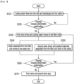
FIGS. 4 and5 are flowcharts for confirming thermal runaway and suppressing thermal runaway of the battery pack ofFIG. 1 . -
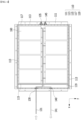
FIG. 6 is a diagram showing the upper surface frame of the battery pack according to a comparative example under the state in which the upper pack frame thereof is removed. - Hereinafter, various embodiments of the present disclosure will be described in detail with reference to the accompanying drawings so that those skilled in the art can easily carry out them. The present disclosure may be modified in various different ways, and is not limited to the embodiments set forth herein.
- A description of portions that are not related to the description will be omitted for clarity, and same reference numerals designate same or like elements throughout the description.
- Further, in the drawings, the size and thickness of each element are arbitrarily illustrated for convenience of description, and the present disclosure is not necessarily limited to those illustrated in the drawings. In the drawings, the thickness of layers, areas, etc. are exaggerated for clarity. In the drawings, for convenience of description, the thicknesses of a part and an area are exaggerated.
- Further, throughout the description, when a portion is referred to as "including" or "comprising" a certain component, it means that the portion can further include other components, without excluding the other components, unless otherwise stated.
- Further, throughout the description, when referred to as "planar", it means when a target portion is viewed from the upper side, and when it is referred to as "cross-sectional", it means when a target portion is viewed from the side of a cross section cut vertically.
- Now, a battery pack according to one embodiment of the present disclosure will be described.
-
FIG. 1 is a perspective view showing a battery pack according to an embodiment of the present disclosure.FIG. 2 is a diagram showing the upper surface frame of the battery pack ofFIG. 1 under the state in which the upper pack frame thereof is removed. - Referring to
FIGS. 1 and2 , thebattery pack 1000 according to an embodiment of the present disclosure comprisesbattery pack frames module part 1170 to which a plurality ofbattery modules 1600 are mounted and anelectrical part 1190 to which electrical components are mounted; aninlet 1300 that supplies cooling water to themodule part 1170; anoutlet 1400 through which the cooling water supplied to themodule part 1170 is discharged; and awater port 1500 that sprays water inside themodule part 1170. - The
battery pack frames lower pack frame 1100 to which a plurality ofbattery modules 1600 are mounted and anupper pack frame 1200 located on an upper part of thebattery module 1600. Herein, thelower pack frame 1100 and theupper pack frame 1200 can be coupled to each other by a method such as welding to seal the inside of thebattery pack 1000. However, the shape of thebattery pack frames battery modules 1600 can be included in the present embodiment. - The
lower pack frame 1100 may comprise abottom part 1110 in contact with the lower surface of thebattery module 1600 and aside surface frame 1130 that houses a plurality ofbattery modules 1600. Herein, thebottom part 1110 and theside surface frame 1130 may be integrated with each other, or may be fixed to each other through a separate fastening method such as welding or adhesion. - In the
lower pack frame 1100, at least onepartition wall 1150 may be formed within theside surface frame 1130. In one example, as shown inFIG. 2 , thelower pack frame 1100 may have apartition wall 1150 formed at a position that distinguishes themodule part 1170 and theelectrical part 1190. However, the present disclosure is not limited thereto, and thepartition wall 1150 may be omitted, and may also be located between a pair of adjacent battery modules among the plurality ofbattery modules 1600 mounted on themodule part 1170. Herein, thepartition wall 1150 may be integrated with thebottom part 1110 and/or theside surface frame 1130, or may be fixed to each other by a separate fastening method such as welding or adhesion. - Further, the battery pack frames 1100 and 1200 may be made of an insulating member. In one example, the battery pack frames 1100 and 1200 may be composed of an aluminum extrusion structure. In another example, the battery pack frames 1100 and 1200 may be made of a dissimilar metal bonding material such as clad metal, or may be a structure containing an insulating material such as aerogel or EPP (Expanded Polypropylene) foam. However, the present disclosure is not limited thereto, and the battery pack frames 1100 and 1200 can be used without limitation as long as they are made of a heat-insulating material having a prescribed rigidity.
- Although not specifically shown in
FIGS. 1 and2 , in thebattery pack 1000 according to this embodiment, a plurality ofbattery modules 1600 mounted on themodule part 1170 may include a battery cell stack in which a plurality of battery cells are stacked, and a module frame that houses the battery cell stack. Herein, the battery cell is preferably a pouch type battery cell. In one example, the battery cell may be produced by housing the electrode assembly in a pouch case of a laminate sheet including a resin layer and an inner layer, and then heat-sealing a sealing part of the pouch case. Such battery cells may be configured by a plurality of numbers, and the plurality of battery cells are stacked so as to be electrically connected to each other, thereby forming a battery cell stack. Herein, the number of battery cells forming the battery cell stack may be adjusted according to circumstances. - The module frame may have a structure in which an upper cover covers a U-shaped frame. Specifically, the upper cover can be coupled to the U-shaped frame by welding or the like in a state in which the corner portions corresponding to each other are in contact with each other, to thereby form a structure that covers the top, bottom, left and right of the battery cell stack. In another example, the module frames may be replaced with a metal plate-shaped mono frame in which the upper and lower surfaces and both side surfaces integrated. In another example, the module frames may be replaced with a shape in which two L-shaped frames are coupled. In another example, the module frames may be replaced with a frame of a 4-plate structure in which an upper surface plate, a lower surface plate, a left plate, and a right plate are coupled. However, the present disclosure is not limited thereto, and any frame can be applied to the present embodiment as long as it can protect the internal components of the
battery module 1600. - In addition, the
battery module 1600 according to another embodiment of the present disclosure may have a structure in which the module frame is eliminated. That is, thebattery pack 1000 according to the present embodiment may has a structure in which the module frame is eliminated among the components of thebattery module 1600, thereby reducing the weight of thebattery pack 1000 and also further increasing the space utilization rate inside thebattery pack 1000. - Although not specifically illustrated in
FIGS. 1 and2 , in thebattery pack 1000 according to the present embodiment, theelectrical part 1190 may be equipped with at least a part of other electrical components and acontrol system 2000 such as a BMS 2200 (FIG. 3 ). - Referring to
FIGS. 1 and2 , in thebattery pack 1000 according to the present embodiment, theinlet 1300, theoutlet 1400, and thewater port 1500 may be located apart from each other at one side surface of the battery pack frames 1100 and 1200. In one example, as shown inFIG. 2 , theinlet 1300, theoutlet 1400 and thewater port 1500 may be located apart from each other on one side surface of thelower pack frame 1100. However, the positions of theinlet 1300, theoutlet 1400, and thewater port 1500 are not limited to those illustrated inFIGS. 1 and2 , any position can be included in the present embodiment as long as it can a position that can appropriately perform supply and/or discharge of cooling water or water. - Referring to
FIG. 2 , theinlet 1300 is connected to theinlet pipe 1310 that supplies cooling water, thewater port 1500 is connected to awater pipe 1510 branched from theinlet pipe 1310, and theoutlet 1400 may be connected to afirst outlet pipe 1410 that discharges the cooling water to the outside. In one example, theinlet 1300 and theinlet pipe 1310, thewater port 1500 and thewater pipe 1510, and theoutlet 1400 and thefirst outlet pipe 1410 may each be fixed to each other using separate fastening methods such as welding or adhesion. - Herein, the
inlet 1300 may supply cooling water to themodule part 1170, and theoutlet 1400 may discharge cooling water supplied to themodule part 1170. In one example, as shown inFIG. 2 , the cooling water supplied to theinlet 1300 may move to coolingflow passages 1350 that are respectively connected to heat sinks (not shown) that cool the plurality ofbattery modules 1600 mounted on themodule part 1170. Further, the cooling water flowing into the coolingflow passages 1350 may pass through the inside of the heat sink (not shown) and then move to thedischarge flow passage 1450, and the cooling water that has moved to thedischarge flow passage 1450 may be discharged to the outside through theoutlet 1400. At this time, although not illustrated inFIG. 2 , the heat sink may be located inside the plurality ofbattery modules 1600 or may be located on the lower surface of the plurality ofbattery modules 1600. - A first valve V1 may be located between the
inlet pipe 1310 and thewater pipe 1510. Herein, the first valve V1 may allow the cooling water to flow into one of theinlet pipe 1310 and thewater pipe 1510. In one example, when the first valve V1 does not operate, the cooling water flowing into theinlet pipe 1310 may move to theinlet 1300. Conversely, when the first valve V1 operates, the cooling water flowing into theinlet pipe 1310 may flow into thewater pipe 1510 and move to thewater port 1500. - Further, the
battery pack 1000 according to the present embodiment may include a first valve driving unit 2400 (FIG. 3 ) that drives and stops the first valve V1. Herein, the first valve driving unit 2400 (FIG. 3 ) can stop the first valve V1 and allow the cooling water to flow into theinlet pipe 1310. Herein, stopping the first valve V1 means that the first valve V1 is not operated or driven. Further, the first valve driving unit 2400 (FIG. 3 ) may drive the first valve V1 and allow the cooling water to flow into thewater pipe 1510. - Thereby, in the
battery pack 1000 according to the present embodiment, a first valve V1 is located between theinlet pipe 1310 and thewater pipe 1510, so that the flow of cooling water flowing into theinlet pipe 1310 can be easily changed depending on the internal situation of thebattery pack 1000. - Referring to
FIGS. 1 and2 , thewater pipe 1510 may have a filter unit F formed between thewater port 1500 and the first valve V1. Herein, the filter unit F can separate materials contained in the cooling water flowing into thewater pipe 1510 from each other. More specifically, the filter unit F separates water and residual materials in the cooling water flowing into thewater pipe 1510, and only the water separated in the filter unit F can flow into thewater port 1500. - In one example, the cooling water may include water and residual materials. In particular, the cooling water is usually made of antifreeze to prevent it from freezing even at low temperatures, and is usually a mixture of water and ethylene glycol in a ratio of 1:1. In other cases, the cooling water may be mostly a mixture of water and some organic solvents.
- In one example, the residual materials may include materials such as ethylene glycol and/or diethylene glycol. Further, the residual materials may include cooling water additives such as phosphates, silicates, and the like. However, the residual materials are not limited thereto, and any material can be included in the present embodiment as long as it is a material necessary to cool the
battery module 1600. - In one example, the filter unit F may be a membrane filter formed of a porous membrane. Herein, similar to the pervaporation method, the filter unit F may be a membrane filter that can separate the cooling water into water and residual materials by partial evaporation through a porous membrane. However, the present disclosure is not limited thereto, and any filter can be included in this embodiment as long as it is a filter that can separate the cooling water into water and residual materials.
- Therefore, in the
battery pack 1000 according to the present embodiment, when thermal runaway occurs inside thebattery pack 1000, oxygen inside themodule part 1170 can be blocked off through the water supplied to thewater port 1500, thereby preventing additional ignition and/or explosion that may occur inside thebattery pack 1000. - Unlike the same, when residual materials excluding water from the cooling water are sprayed into the
module part 1170 and the inside of thebattery pack 1000 or the battery module 100 is water-infiltrated, the residual materials contained in the cooling water may cause high-voltage insulation breakdown of components contained within thebattery pack 1000. Further, due to high-voltage insulation breakdown induced by components included inside thebattery pack 1000, there is a problem that ignition may occur inside thebattery pack 1000 and a fire may occur inside thebattery pack 1000. - Thereby, in the
battery pack 1000 according to the present embodiment, only the water contained in the cooling water flowing into thewater pipe 1510 through the filter unit F included in thewater pipe 1510 can be flowed into thebattery pack 1000, so that insulation breakdown induced by the residual materials contained in the cooling water can be prevented. - Referring to
FIGS. 1 and2 , the filter unit F may be connected to asecond outlet pipe 1550 that is branched from thewater pipe 1510 and connected thereto. Further, a second valve V2 may be located between thefirst outlet pipe 1410 and thesecond outlet pipe 1550. Herein, the second valve V2 may discharge materials moved from one of thefirst outlet pipe 1410 and thesecond outlet pipe 1550. In one example, if the second valve V2 is not operated, the materials discharged to theoutlet 1400 may be discharged to the outside through thefirst outlet pipe 1410. Conversely, when the second valve V2 is operated, materials that have moved to thesecond outlet pipe 1550 may be discharged to the outside through thefirst outlet pipe 1410. Herein, the material discharged from theoutlet 1400 is the cooling water flowing into theinlet 1300, and the material moved to thesecond outlet pipe 1550 may be the residual materials separated from the filter unit F among the cooling water flowing into thewater pipe 1510. - Further, the
battery pack 1000 according to the present embodiment may include a second valve driving unit 2500 (FIG. 3 ) that drives and stops the second valve V2. Herein, the second valve driving unit 2500 (FIG. 3 ) may stop the second valve V2 and allow the cooling water discharged from theoutlet 1400 to be discharged to the outside through thefirst outlet pipe 1410. Herein, stopping the second valve V2 means that the second valve V2 is not operated or driven. Further, the second valve driving unit 2500 (FIG. 3 ) drives the second valve V2, so that the residual material separated from the filter unit F moving through theoutlet pipe 1550 can be discharged to the outside through thefirst outlet pipe 1410. - Thereby, in the
battery pack 1000 according to the present embodiment, the second valve V2 is located between the filter unit F and thefirst outlet pipe 1410, so that the type of materials discharged to the outside through thefirst outlet pipe 1410 can be easily changed depending on the internal situation of thebattery pack 1000. - Referring to
FIGS. 2 and3 , thebattery pack 1000 according to the present embodiment is connected to thewater port 1500, and may include at least onespraying unit 1155 located adjacent to themodule part 1170. More specifically, thespraying unit 1155 may spray water flowing into thewater port 1500 toward themodule part 1170. Herein, thespraying unit 1155 may adjust the spraying speed and/or amount of water based on the shape and number ofbattery modules 1600 mounted inside themodule part 1170. - In one example, the
spraying unit 1155 may be made of an insulating and/or flame-retardant material. In another example, thespraying unit 1155 may be made of a material such as aluminum depending on other designs. However, the present disclosure is not limited thereto, and any material can be included in the present embodiment as long as it is a material that can spray water toward themodule part 1170 without being damaged when thermal runaway of thebattery pack 1000 occurs. - Further, in the
battery pack 1000 according to the present embodiment, at least onespraying unit 1155 may be located apart from each other on thepartition wall 1150. In one example, thespraying unit 1155 may be located at the 2/3 point of thepartition wall 1150. - In another example, in the case of the
battery pack 1000 in which thepartition wall 1150 is omitted, thespraying unit 1155 may be located adjacent to the battery module located closest to thewater port 1500 among the plurality ofbattery modules 1600. Herein, the number and position of thespraying unit 1155 are not limited to those shown inFIG. 2 , and the number and position of thebattery modules 1600 may be adjusted based on the shape, number and the like of thebattery modules 1600. - Thereby, in the
battery pack 1000 according to the present embodiment, only water among the cooling water can be directly sprayed onto themodule part 1170 via thespray unit 1155, whereby while preventing insulation breakdown due to the residual materials contained in the cooling water, oxygen inside themodule portion 1170 can be effectively blocked off when thermal runaway occurs inside thebattery pack 1000. In addition, thebattery pack 1000 according to the present embodiment can effectively prevent additional ignition and/or explosion that may occur inside thebattery pack 1000. -
FIG. 3 is a diagram showing a battery pack system that controls the battery pack ofFIG. 1 .FIGS. 4 and5 are flowcharts for confirming thermal runaway and suppressing thermal runaway of the battery pack ofFIG. 1 . - Referring to
FIG. 3 , thebattery pack 1000 according to the present embodiment can be controlled by abattery pack system 2000 that includes acontrol unit 2100, a BMS(battery management system) 2200, avalve control unit 2300, a firstvalve driving unit 2400, and a secondvalve driving unit 2500. - More specifically, the
control unit 2100 may control a BMS (battery management system) 2200 and avalve control unit 2300. Thecontrol unit 2100 may include at least one of a CPU (central processing unit), a RAM (random access memory), a GPU (graphic processing unit), one or more microprocessors, and other electronic components that can process input data according to predetermined logic. In one example, thecontrol unit 2100 develops a thermal runaway confirmation process and a thermal runaway prevention process that can be performed by thebattery pack system 2000 on RAM, and can perform various processes, such as controlling the BMS (Battery Management System) 2200 and thevalve control unit 2300 according to the developed program. - BMS(battery management system) 2200 can measure the voltage and temperature of battery cells included in a plurality of
battery modules 1600. More specifically, theBMS 2200 can estimate the state of the battery cell mounted inside thebattery module 1600 and manage thebattery pack 1000 using the estimated state information. In one example, theBMS 2200 can measure and manage the voltage and temperature of the battery cell as the status of the battery cell. In the present embodiment, theBMS 2200 may provide status information about the measured voltage and temperature of the battery cell to thecontrol unit 2100. - Referring to
FIGS. 2 to 4 , as a process for confirming thermal runaway of thebattery pack 1000 of the present embodiment, theBMS 2200 may measure the voltage and temperature of the battery cell (S110). At this time, it is possible to confirm whether the measured voltage of the battery cell is 0.5V or less (S120). Herein, the measured voltage of the battery cell may mean the highest voltage among the voltages measured in a plurality of battery cells (not shown) included in the plurality ofbattery modules 1600. If the measured voltage of the battery cell is less than 0.5V, it is possible to confirm whether the temperature of the battery cell is 70 degrees Celsius or more (S130). If the temperature of the battery cell is 70 degrees Celsius or more, thecontrol unit 2100 may acquire thermal runaway abnormality confirmation information indicating that thermal runaway abnormality has occurred inside thebattery pack 1000 based on information provided by theBMS 2200. After that, thecontrol unit 2100 may transmit a notification to the vehicle to which thebattery pack 1000 is mounted based on the thermal runaway abnormality confirmation information (S150). - Unlike the same, if the measured voltage of the battery cell is more than 0.5V or the temperature of the battery cell is less than 70 degrees Celsius, the
BMS 2200 can continuously measure and manage the voltage and temperature of the battery cell. - Referring to
FIGS. 2 and3 , thevalve control unit 2300 may control the firstvalve driving unit 2400 and the secondvalve driving unit 2500. More specifically, thevalve control unit 2300 can control the firstvalve driving unit 2400 to drive or stop the first valve V1, and thevalve control unit 2300 may control the secondvalve driving unit 2500 to drive or stop the second valve V2. - Referring to
FIGS. 2 ,3 , and5 , as a thermal runaway prevention process of thebattery pack 1000 of the present embodiment, when thecontrol unit 2100 does not acquire thermal runaway abnormality confirmation information, the cooling water may flow into theinlet 1300, and the inflowed coolant may be discharged into the outlet 1400 (S210). After that, when thermal runaway abnormality occurs within thebattery pack 1000, thecontrol unit 2100 may acquire thermal runaway abnormality confirmation information based on the thermal runaway confirmation process (S220). At this time, thevalve control unit 2300 may control the firstvalve driving unit 2400 to drive the first valve V1, and the cooling water may move to the filter unit F via the water pipe 1510 (S230). Here, the cooling water that has moved to the filter unit F is separated into water and the residual material, and the water separated from the filter unit F can move to the water port 1500 (S240). Further, thevalve control unit 2300 can control the secondvalve driving unit 2500 and allow the residual material separated from the filter unit F to move to theoutlet pipes 1410 and 1550 (S250). After that, thecontrol unit 2100 can confirm again whether thermal runaway is abnormal (S260). At this time, if thecontrol unit 2100 does not confirm the thermal runaway abnormality, in other words, if thermal runaway abnormality release information is acquired, thevalve control unit 2300 may stop the first valve V1 and the second valve V2 via the firstvalve driving unit 2400 and the second valve driving unit 2500 (S270). - Thereby, the
battery pack 1000 according to the present embodiment can block off oxygen inside themodule part 1170 through water supplied to thewater port 1500, and can prevent additional ignition and/or explosion that can occur within thebattery pack 1000. -
FIG. 6 is a diagram showing the upper surface frame of the battery pack according to a comparative example under the state in which the upper pack frame thereof is removed. - Referring to
FIG. 6 , unlike the battery pack 1000 (FIGS. 1 to 5 ) according to the present embodiment, the battery pack according to the comparative example has a structure that does not include the first valve V1, the second valve V2, the filter part F, and thewater port 1500, but includes all the other components in the same manner. - Referring to
FIG. 6 , in the case of the battery pack according to the comparative example, no separate components are included to completely prevent ignition and/or explosion of the battery pack when thermal runaway occurs inside the battery pack. Thereby, in the case of the battery pack according to the comparative example, if thermal runaway occurs inside the battery pack, only a delay of several minutes to several tens of minutes is possible, thus making it impossible to prevent additional ignition and/or explosion, and it may be difficult to minimize damage to lives or vehicles without external intervention. - In contrast, referring to
FIGS. 1 to 5 , thebattery pack 1000 according to the present embodiment utilizes the coolant flowing into and being discharged from themodule part 1170, so that water can be directly sprayed on themodule part 1170 via thewater port 1500. Therefore, even if thermal runaway occurs inside thebattery pack 1000, there is an advantage in that additional ignition and/or explosion can be completely blocked off. - According to yet another embodiment of the present disclosure, there can be provided a device comprising the above-mentioned battery pack. Such a device can be applied to vehicle means such as an electric bike, an electric vehicle, and a hybrid electric vehicle, but the present disclosure is not limited thereto, and is applicable to various devices that can use a battery module and a battery pack including the same, which also falls under the scope of the present disclosure.
- Although the invention has been described in detail with reference to preferred embodiments of the present disclosure, the scope of the present disclosure is not limited thereto, and various modifications and improvements can be made by those skilled in the art using the basic concepts of the present disclosure, which are defined in the appended claims, which also falls within the scope of the present disclosure.
-
- 1000: battery pack
- 1100: lower pack frame
- 1200: upper pack frame
- 1300: inlet
- 1310: inlet pipe
- 1400: outlet
- 410: first outlet pipe
- 450: second outlet pipe
- 1500: water port
- 1510: water pipe
- 1600: battery module
- 2000: battery pack system
- 2100: control unit
- 2200: BMS
- 2300: valve control unit
- 2400: first valve driving unit
- 2500: second valve driving unit
- V1: first valve
- V2: second valve
- F: filter unit
Claims (18)
- A battery pack comprising:a battery pack frame that includes a module part to which a plurality of battery modules are mounted and an electrical part to which electrical components are mounted;an inlet that supplies cooling water to the module part;an outlet through which the cooling water supplied to the module part is discharged; anda water port that sprays water inside the module part,wherein the inlet, the outlet, and the water port are located apart from each other at one side surface of the battery pack frame.
- The battery pack of claim 1, wherein:the inlet is connected to an inlet pipe that supplies the cooling water,the water port is connected to a water pipe branched from the inlet pipe, andthe outlet is connected to a first outlet pipe that discharges the cooling water to the outside.
- The battery pack of claim 2, wherein:a first valve is located between the inlet pipe and the water pipe, andthe first valve allows the cooling water to flow into one of the inlet pipe and the water pipe.
- The battery pack of claim 3,
further comprising a first valve driving unit that drives and stops the first valve, wherein:the first valve driving unit stops the first valve and allows the cooling water to flow into the inlet pipe, andthe first valve driving unit drives the first valve and allows the cooling water to flow into the water pipe. - The battery pack of claim 3, wherein:
the water pipe is formed with a filter unit between the water port and the first valve. - The battery pack of claim 5, wherein:the filter unit separates water and residual materials among the cooling water flowing into the water pipe, andthe water separated from the filter unit flows into the water port.
- The battery pack of claim 6, wherein:
the filter unit is a membrane filter formed of a porous membrane. - The battery pack of claim 5, wherein:the filter unit is connected to a second outlet pipe that is branched from the water pipe and connected thereto, anda second valve is located between the first outlet pipe and the second outlet pipe.
- The battery pack of claim 8, wherein:
the second valve discharges material that has moved from one of the first outlet pipe and the second outlet pipe. - The battery pack of claim 9,
further comprising a second valve driving unit that drives and stops the second valve, wherein:the second valve driving unit stops the second valve and discharges materials discharged from the outlet to the outside through the first outlet pipe, andthe second valve driving unit drives the second valve and discharges materials moving into the second outlet pipe to the outside through the first outlet pipe. - The battery pack of claim 10, wherein:the material discharged from the outlet is cooling water that has flowed into the inlet, andthe material that have moved to the second outlet pipe is the residual material that have separated from the filter unit among the cooling water flowing into the water pipe.
- The battery pack of claim 10,further comprising a valve control unit that controls the first valve driving unit and the second valve driving unit,a BMS (Battery Management System) that measures the voltage and temperature of the battery cells included in the plurality of battery modules, anda control unit that controls the valve control unit and the BMS.
- The battery pack of claim 12, wherein:when the voltage of the battery cell measured by the BMS is 0.5V or less and the temperature of the battery cell is than 70 degrees Celsius or more,the control unit acquires thermal runaway abnormality confirmation information, andthe valve control unit controls so that the first valve driving unit and the second valve driving unit drive the first valve and the second valve.
- The battery pack of claim 12, wherein:when the voltage of the battery cell measured by the BMS is more than 0.5V and the temperature of the battery cell is less than 70 degrees Celsius,the control unit acquires thermal runaway abnormality release information, andthe valve control unit controls so that the first valve driving unit and the second valve driving unit stop the first valve and the second valve.
- The battery pack of claim 12, wherein:the battery pack comprises at least one spraying unit connected to the water port and located adjacent to the module part, andthe spraying unit sprays water that has flowed into the water port toward the module part.
- The battery pack of claim 15,further comprising a partition wall located between the module part and the electrical unit,wherein the at least one spraying unit is located apart from each other on the partition wall.
- The battery pack of claim 15, wherein:
the spraying unit is located adjacent to a battery module that is located closest to the water port among the plurality of battery modules. - A device comprising the battery pack of claim 1.
Applications Claiming Priority (3)
| Application Number | Priority Date | Filing Date | Title |
|---|---|---|---|
| KR20220181513 | 2022-12-22 | ||
| KR1020230166391A KR20240100233A (en) | 2022-12-22 | 2023-11-27 | Battery pack and device including the same |
| PCT/KR2023/019333 WO2024136192A1 (en) | 2022-12-22 | 2023-11-28 | Battery pack and device including same |
Publications (2)
| Publication Number | Publication Date |
|---|---|
| EP4498475A1 true EP4498475A1 (en) | 2025-01-29 |
| EP4498475A4 EP4498475A4 (en) | 2025-08-06 |
Family
ID=91589340
Family Applications (1)
| Application Number | Title | Priority Date | Filing Date |
|---|---|---|---|
| EP23907478.4A Pending EP4498475A4 (en) | 2022-12-22 | 2023-11-28 | BATTERY PACK AND DEVICE THEREOF |
Country Status (4)
| Country | Link |
|---|---|
| EP (1) | EP4498475A4 (en) |
| JP (1) | JP7722785B2 (en) |
| CN (1) | CN119013820A (en) |
| WO (1) | WO2024136192A1 (en) |
Family Cites Families (12)
| Publication number | Priority date | Publication date | Assignee | Title |
|---|---|---|---|---|
| CN210516847U (en) * | 2019-10-05 | 2020-05-12 | 上海保岭新能源科技有限公司 | Battery pack ventilation drying and filtering system |
| CN111509163A (en) * | 2020-05-25 | 2020-08-07 | 重庆金康动力新能源有限公司 | Battery pack with fire extinguishing function |
| CN112002958B (en) * | 2020-08-27 | 2022-04-26 | 重庆金康动力新能源有限公司 | Battery pack spraying and cooling system |
| CN112038728B (en) | 2020-08-28 | 2024-06-18 | 浙江南都电源动力股份有限公司 | Cooling fire-fighting mixing system for energy storage device and control method thereof |
| KR102903026B1 (en) * | 2020-11-09 | 2025-12-19 | 주식회사 엘지에너지솔루션 | Battery pack and Vehicle comprising the same |
| CN213546433U (en) * | 2020-11-23 | 2021-06-25 | 安徽沃博源科技有限公司 | Battery pack heat dissipation structure adopting water cooling heat dissipation |
| CN214254526U (en) | 2020-12-23 | 2021-09-21 | 福建时代星云科技有限公司 | Novel lithium battery energy storage container system |
| KR20220100459A (en) * | 2021-01-08 | 2022-07-15 | 현대모비스 주식회사 | Battery module cooling structure |
| CN112820978B (en) * | 2021-01-13 | 2022-09-06 | 傲普(上海)新能源有限公司 | Battery box liquid cooling heat dissipation and fire extinguishing system |
| CN113117274A (en) * | 2021-04-09 | 2021-07-16 | 北京科易动力科技有限公司 | Cooling system for battery pack |
| CN113764772A (en) * | 2021-08-27 | 2021-12-07 | 中国第一汽车股份有限公司 | Fire suppression device and method for power battery pack, power battery pack and vehicle |
| KR20230166391A (en) | 2022-05-30 | 2023-12-07 | 임명순 | The flag that wraps around the flagpole |
-
2023
- 2023-11-28 WO PCT/KR2023/019333 patent/WO2024136192A1/en not_active Ceased
- 2023-11-28 CN CN202380034262.7A patent/CN119013820A/en active Pending
- 2023-11-28 JP JP2024559920A patent/JP7722785B2/en active Active
- 2023-11-28 EP EP23907478.4A patent/EP4498475A4/en active Pending
Also Published As
| Publication number | Publication date |
|---|---|
| WO2024136192A1 (en) | 2024-06-27 |
| CN119013820A (en) | 2024-11-22 |
| JP2025512002A (en) | 2025-04-16 |
| JP7722785B2 (en) | 2025-08-13 |
| EP4498475A4 (en) | 2025-08-06 |
Similar Documents
| Publication | Publication Date | Title |
|---|---|---|
| US20230291064A1 (en) | Battery module with thermal propagation prevention structure of battery cell using coolant and battery pack comprising the same | |
| EP2002496B1 (en) | Battery pack comprising combined temperature-controlling system | |
| KR102697829B1 (en) | Cooling systems and methods | |
| EP4199227A1 (en) | Battery pack and device comprising same | |
| CN110462921B (en) | Cooling systems and methods | |
| KR102892942B1 (en) | Battery pack | |
| EP4016703A1 (en) | Battery module and battery pack including same | |
| JP7436125B2 (en) | Battery module and battery pack containing it | |
| US20240063501A1 (en) | Battery pack and device including the same | |
| KR102868573B1 (en) | Battery box body, battery, electric device, battery manufacturing method and device | |
| US20240387897A1 (en) | Battery pack and vehicle including the same | |
| EP4148875A1 (en) | Battery pack and device including same | |
| EP4109649B1 (en) | Battery module and battery pack including the same | |
| EP4040577A1 (en) | Battery pack and device including same | |
| KR20240100233A (en) | Battery pack and device including the same | |
| CN117423925A (en) | Thermal management system with passive containment bag for liquid immersion cooling of battery assembly | |
| EP4266456A1 (en) | Battery module and battery pack including same | |
| US20240113357A1 (en) | Battery pack and device including the same | |
| JP7722785B2 (en) | Battery packs and devices containing them | |
| EP4679569A1 (en) | Battery module, battery pack, and vehicle including same | |
| EP4712211A1 (en) | Battery pack and vehicle including same | |
| US20220376328A1 (en) | Secondary battery cooling structure | |
| EP4604297A1 (en) | Battery pack and device including same | |
| EP4683045A1 (en) | Battery pack and device including same | |
| KR20250145887A (en) | Battery pack and vehicle including the same |
Legal Events
| Date | Code | Title | Description |
|---|---|---|---|
| STAA | Information on the status of an ep patent application or granted ep patent |
Free format text: STATUS: THE INTERNATIONAL PUBLICATION HAS BEEN MADE |
|
| PUAI | Public reference made under article 153(3) epc to a published international application that has entered the european phase |
Free format text: ORIGINAL CODE: 0009012 |
|
| STAA | Information on the status of an ep patent application or granted ep patent |
Free format text: STATUS: REQUEST FOR EXAMINATION WAS MADE |
|
| 17P | Request for examination filed |
Effective date: 20241021 |
|
| AK | Designated contracting states |
Kind code of ref document: A1 Designated state(s): AL AT BE BG CH CY CZ DE DK EE ES FI FR GB GR HR HU IE IS IT LI LT LU LV MC ME MK MT NL NO PL PT RO RS SE SI SK SM TR |
|
| A4 | Supplementary search report drawn up and despatched |
Effective date: 20250708 |
|
| RIC1 | Information provided on ipc code assigned before grant |
Ipc: H01M 10/42 20060101AFI20250702BHEP Ipc: A62C 3/16 20060101ALI20250702BHEP Ipc: A62C 99/00 20100101ALI20250702BHEP Ipc: A62C 35/68 20060101ALI20250702BHEP Ipc: A62C 37/36 20060101ALI20250702BHEP Ipc: H01M 50/20 20210101ALI20250702BHEP Ipc: H01M 10/613 20140101ALI20250702BHEP Ipc: H01M 10/48 20060101ALI20250702BHEP Ipc: H01M 10/6568 20140101ALI20250702BHEP Ipc: H01M 50/204 20210101ALI20250702BHEP Ipc: A62C 3/07 20060101ALI20250702BHEP Ipc: H01M 10/633 20140101ALI20250702BHEP |
|
| DAV | Request for validation of the european patent (deleted) | ||
| DAX | Request for extension of the european patent (deleted) |