EP4498445A2 - Negative electrode sheet, battery, and electricity-consumption device - Google Patents
Negative electrode sheet, battery, and electricity-consumption device Download PDFInfo
- Publication number
- EP4498445A2 EP4498445A2 EP24182790.6A EP24182790A EP4498445A2 EP 4498445 A2 EP4498445 A2 EP 4498445A2 EP 24182790 A EP24182790 A EP 24182790A EP 4498445 A2 EP4498445 A2 EP 4498445A2
- Authority
- EP
- European Patent Office
- Prior art keywords
- active material
- negative active
- electrode sheet
- heat release
- battery
- Prior art date
- Legal status (The legal status is an assumption and is not a legal conclusion. Google has not performed a legal analysis and makes no representation as to the accuracy of the status listed.)
- Pending
Links
Images


Classifications
-
- H—ELECTRICITY
- H01—ELECTRIC ELEMENTS
- H01M—PROCESSES OR MEANS, e.g. BATTERIES, FOR THE DIRECT CONVERSION OF CHEMICAL ENERGY INTO ELECTRICAL ENERGY
- H01M4/00—Electrodes
- H01M4/02—Electrodes composed of, or comprising, active material
- H01M4/36—Selection of substances as active materials, active masses, active liquids
- H01M4/58—Selection of substances as active materials, active masses, active liquids of inorganic compounds other than oxides or hydroxides, e.g. sulfides, selenides, tellurides, halogenides or LiCoFy; of polyanionic structures, e.g. phosphates, silicates or borates
- H01M4/583—Carbonaceous material, e.g. graphite-intercalation compounds or CFx
-
- H—ELECTRICITY
- H01—ELECTRIC ELEMENTS
- H01M—PROCESSES OR MEANS, e.g. BATTERIES, FOR THE DIRECT CONVERSION OF CHEMICAL ENERGY INTO ELECTRICAL ENERGY
- H01M10/00—Secondary cells; Manufacture thereof
- H01M10/05—Accumulators with non-aqueous electrolyte
- H01M10/052—Li-accumulators
- H01M10/0525—Rocking-chair batteries, i.e. batteries with lithium insertion or intercalation in both electrodes; Lithium-ion batteries
-
- H—ELECTRICITY
- H01—ELECTRIC ELEMENTS
- H01M—PROCESSES OR MEANS, e.g. BATTERIES, FOR THE DIRECT CONVERSION OF CHEMICAL ENERGY INTO ELECTRICAL ENERGY
- H01M10/00—Secondary cells; Manufacture thereof
- H01M10/05—Accumulators with non-aqueous electrolyte
- H01M10/054—Accumulators with insertion or intercalation of metals other than lithium, e.g. with magnesium or aluminium
-
- H—ELECTRICITY
- H01—ELECTRIC ELEMENTS
- H01M—PROCESSES OR MEANS, e.g. BATTERIES, FOR THE DIRECT CONVERSION OF CHEMICAL ENERGY INTO ELECTRICAL ENERGY
- H01M4/00—Electrodes
- H01M4/02—Electrodes composed of, or comprising, active material
- H01M4/13—Electrodes for accumulators with non-aqueous electrolyte, e.g. for lithium-accumulators; Processes of manufacture thereof
- H01M4/133—Electrodes based on carbonaceous material, e.g. graphite-intercalation compounds or CFx
-
- H—ELECTRICITY
- H01—ELECTRIC ELEMENTS
- H01M—PROCESSES OR MEANS, e.g. BATTERIES, FOR THE DIRECT CONVERSION OF CHEMICAL ENERGY INTO ELECTRICAL ENERGY
- H01M4/00—Electrodes
- H01M4/02—Electrodes composed of, or comprising, active material
- H01M4/36—Selection of substances as active materials, active masses, active liquids
-
- H—ELECTRICITY
- H01—ELECTRIC ELEMENTS
- H01M—PROCESSES OR MEANS, e.g. BATTERIES, FOR THE DIRECT CONVERSION OF CHEMICAL ENERGY INTO ELECTRICAL ENERGY
- H01M4/00—Electrodes
- H01M4/02—Electrodes composed of, or comprising, active material
- H01M4/36—Selection of substances as active materials, active masses, active liquids
- H01M4/58—Selection of substances as active materials, active masses, active liquids of inorganic compounds other than oxides or hydroxides, e.g. sulfides, selenides, tellurides, halogenides or LiCoFy; of polyanionic structures, e.g. phosphates, silicates or borates
- H01M4/583—Carbonaceous material, e.g. graphite-intercalation compounds or CFx
- H01M4/587—Carbonaceous material, e.g. graphite-intercalation compounds or CFx for inserting or intercalating light metals
-
- H—ELECTRICITY
- H01—ELECTRIC ELEMENTS
- H01M—PROCESSES OR MEANS, e.g. BATTERIES, FOR THE DIRECT CONVERSION OF CHEMICAL ENERGY INTO ELECTRICAL ENERGY
- H01M4/00—Electrodes
- H01M4/02—Electrodes composed of, or comprising, active material
- H01M2004/021—Physical characteristics, e.g. porosity, surface area
-
- H—ELECTRICITY
- H01—ELECTRIC ELEMENTS
- H01M—PROCESSES OR MEANS, e.g. BATTERIES, FOR THE DIRECT CONVERSION OF CHEMICAL ENERGY INTO ELECTRICAL ENERGY
- H01M4/00—Electrodes
- H01M4/02—Electrodes composed of, or comprising, active material
- H01M2004/026—Electrodes composed of, or comprising, active material characterised by the polarity
- H01M2004/027—Negative electrodes
-
- H—ELECTRICITY
- H01—ELECTRIC ELEMENTS
- H01M—PROCESSES OR MEANS, e.g. BATTERIES, FOR THE DIRECT CONVERSION OF CHEMICAL ENERGY INTO ELECTRICAL ENERGY
- H01M2220/00—Batteries for particular applications
- H01M2220/20—Batteries in motive systems, e.g. vehicle, ship, plane
-
- H—ELECTRICITY
- H01—ELECTRIC ELEMENTS
- H01M—PROCESSES OR MEANS, e.g. BATTERIES, FOR THE DIRECT CONVERSION OF CHEMICAL ENERGY INTO ELECTRICAL ENERGY
- H01M4/00—Electrodes
- H01M4/02—Electrodes composed of, or comprising, active material
- H01M4/62—Selection of inactive substances as ingredients for active masses, e.g. binders, fillers
-
- Y—GENERAL TAGGING OF NEW TECHNOLOGICAL DEVELOPMENTS; GENERAL TAGGING OF CROSS-SECTIONAL TECHNOLOGIES SPANNING OVER SEVERAL SECTIONS OF THE IPC; TECHNICAL SUBJECTS COVERED BY FORMER USPC CROSS-REFERENCE ART COLLECTIONS [XRACs] AND DIGESTS
- Y02—TECHNOLOGIES OR APPLICATIONS FOR MITIGATION OR ADAPTATION AGAINST CLIMATE CHANGE
- Y02E—REDUCTION OF GREENHOUSE GAS [GHG] EMISSIONS, RELATED TO ENERGY GENERATION, TRANSMISSION OR DISTRIBUTION
- Y02E60/00—Enabling technologies; Technologies with a potential or indirect contribution to GHG emissions mitigation
- Y02E60/10—Energy storage using batteries
Definitions
- This disclosure relates to the technical field of electrode materials, and in particular to a negative electrode sheet, a battery, and an electricity-consumption device.
- a secondary battery such as a lithium-ion battery and a sodium-ion battery
- a secondary battery is widely used in fields such as electric vehicles, portable mobile devices, and aerospace because the secondary battery has high energy density, a long service life, no memory effect, a low self-discharge rate, etc.
- the secondary battery still has serious safety concerns. Smoking, combustion, explosion, and other safety accidents caused by thermal runaway of the battery are the most common concerns.
- the present disclosure is intended to provide a negative electrode sheet, a battery, and an electricity-consumption device, so as to reduce occurrence of thermal runaway of the negative electrode sheet during operation.
- a negative electrode sheet in the present disclosure.
- the negative electrode sheet includes a current collector and a negative active material layer disposed on the current collector.
- the negative active material layer includes a negative active material.
- a differential scanning calorimeter (DSC) curve of the negative active material layer includes: a first exothermic peak from 120 °C to 150 °C, in which the negative active material layer has heat release A1 satisfying 2 J/g ⁇ A1 ⁇ 50 J/g; a second exothermic peak from 220 °C to 260 °C, in which the negative active material layer has heat release A2 satisfying 20 J/g ⁇ A2 ⁇ 100 J/g; and a third exothermic peak from 260 °C to 310 °C, in which the negative active material layer has heat release A3 satisfying 200 J/g ⁇ A3 ⁇ 600 J/g.
- the heat release corresponding to the first exothermic peak is controlled within the above range, so that a content of a solid electrolyte interface (SEI) generated on the negative active material can be ensured to be within an appropriate range, thereby balancing electrochemical performance of the battery. If the heat release A1 corresponding to the first exothermic peak is below the above range, it indicates that the negative active material has a relatively low content and poor quality of the SEI, so that the SEI tends to be broken in the later cycles and side reaction is prone to occur between active ions in the negative active material and the electrolyte, which will affect capacity and cycle life of the battery.
- SEI solid electrolyte interface
- the heat release A1 corresponding to the first exothermic peak is above the above range, it indicates that the negative active material has a relatively high content of the SEI, so that a lot of active ions are consumed in a first cycle. In this case, the capacity of the battery is reduced, and an interface of the negative active material is extremely unstable, so that the thermal runaway is easily aggravated.
- the heat release corresponding to the second exothermic peak is controlled within the above range, so that the negative active material can be ensured to have strong thermal stability in the electrolyte, thereby balancing so that the electrochemical performance of the battery and avoiding the thermal runaway. If the heat release A2 corresponding to the second exothermic peak is below the above range, it indicates that reaction between the negative active material and the electrolyte is relatively weak and dead lithium (inactive alkali metal ion) is too much, so that the battery capacity is poor.
- the heat release corresponding to the third exothermic peak is controlled within the above range, so that the negative active material can be ensured to have strong thermal stability with a binder, thereby balancing the electrochemical performance of the battery and avoiding the thermal runaway. If the heat release A3 corresponding to the third exothermic peak is below t the above range, it indicates that reaction between the binder and lithiated graphite is relatively weak and dead lithium (inactive alkali metal ion) is too much, so that the battery capacity is poor.
- the negative active material satisfying the above relationship can significantly improve high-temperature stability of the negative electrode sheet with the negative active material.
- an assembled battery can be ensured to maintain relatively low heat release in three different heat release stages under a high-temperature operating environment, so that relatively high heat release due to excessive temperature can be avoided in the three heat release stages, and the thermal runaway can be avoided.
- heat release in each temperature range is controlled within a range that the battery can tolerate, so that the battery will not spontaneously combust or explode due to excessive heat, which means that the negative electrode sheet has excellent high-temperature stability.
- peak shapes of the first exothermic peak, the second exothermic peak, and the third exothermic peak include one or any combination of a single characteristic peak shape, a double shoulder peak shape, or a continuous peak shape.
- the heat release A1 corresponding to the first exothermic peak and the heat release A3 corresponding to the third exothermic peak satisfy: 0.003 ⁇ A1 / A3 ⁇ 0.25. If A1 / A3 is less than 0.003, it indicates that the quality of the SEI is poor, and reactivity of the binder and the lithiated graphite is high, so that the battery life will be affected. If A1 / A3 is greater than 0.25, it indicates that the SEI is too thick and extremely unstable, and the SEI is prone to be broken to generate a large amount of heat, so that the thermal runaway is more likely to occur.
- the heat release A2 corresponding to the second exothermic peak and the heat release A3 corresponding to the third exothermic peak satisfy: 0.03 ⁇ A2 / A3 ⁇ 0.5. If A2 / A3 is less than 0.03, it indicates that dead lithium in the lithiated graphite is too much, and the reactivity of the binder and the lithiated graphite is high, so that the battery life will be affected. If A2 / A3 is greater than 0.5, it indicates that reaction between the lithiated graphite and the electrolyte is strong and a large amount of heat is generated, so that the thermal runaway of the battery is triggered.
- a particle diameter Dv50 of the negative active material satisfies 10 ⁇ m ⁇ Dv 50 ⁇ 17 ⁇ m, where the Dv50 refers to a particle diameter when a cumulative volume fraction reaches 50% in measuring a volume-based distribution using a laser scattering method.
- the particle diameter of the negative active material is below the above range, it indicates that the negative active material 11 in the negative active material layer has a relatively small particle diameter, which not only easily causes a lot of side reactions but also increases preparation difficulty of the negative active material. In this case, the negative active material is easily agglomerated and difficultly subdivided. When the particle diameter of the negative active material is above the above range, the particle is too large, so that storage sites of alkali metal ions decrease and capacity of the battery is relatively poor.
- the specific surface area of the negative active material satisfies 1.1 m 2 /g to 4.5 m 2 /g. Since the specific surface area will affect initial coulombic efficiency (ICE) of the negative active material and deintercalation of the active ions (lithium-ions or sodium-ions), a larger specific surface area causes lower ICE, a smaller specific surface area is not conducive to the deintercalation of the active ions, and the specific surface area of the negative active material maintained within the above range can ensure that the negative active material can have excellent electrochemical performance.
- ICE initial coulombic efficiency
- a gram capacity of the negative active material ranges from 330 mAh/g to 360 mAh/g.
- the negative active material is one or more of a graphite particle, a soft carbon particle, or a hard carbon particle.
- the graphite particle may be natural graphite or artificial graphite, which is not limited in the present disclosure.
- a shape of the graphite particle is not limited and may be spherical, plate-shaped, etc.
- a graphite material is the most widely used negative active material.
- the graphite material has good conductivity, which can not only improve conductivity of a silicon material but also increase capacity.
- a battery is further provided in the present disclosure.
- the battery includes electrolyte, a positive electrode sheet, a separator, and the negative electrode sheet of the first aspect.
- the positive electrode sheet is at least partially immersed in the electrolyte.
- the separator is located at one side of the positive electrode sheet and is at least partially immersed in the electrolyte.
- the negative electrode sheet is disposed at one side of the separator away from the positive electrode sheet and at least partially immersed in the electrolyte. It can be understood that the battery has all technical effects of the negative electrode sheet of the first aspect, which is not repeated herein.
- the negative electrode sheet includes a current collector and a negative active material layer disposed on the current collector.
- the negative active material layer includes a negative active material.
- a differential scanning calorimeter (DSC) curve of the negative active material layer includes: a first exothermic peak from 120 °C to 150 °C, in which the negative active material layer has heat release A1 satisfying 2 J/g ⁇ A1 ⁇ 50 J/g; a second exothermic peak from 220 °C to 260 °C, in which the negative active material layer has heat release A2 satisfying 20 J/g ⁇ A2 ⁇ 100 J/g; and a third exothermic peak from 260 °C to 310 °C, in which the negative active material layer has heat release A3 satisfying 200 J/g ⁇ A3 ⁇ 600 J/g.
- an electricity-consumption device is further provided in the present disclosure.
- the electricity-consumption device includes a battery.
- the battery includes electrolyte, a positive electrode sheet, a separator, and the negative electrode sheet of the first aspect.
- the positive electrode sheet is at least partially immersed in the electrolyte.
- the separator is located at one side of the positive electrode sheet and is at least partially immersed in the electrolyte.
- the negative electrode sheet is disposed at one side of the separator away from the positive electrode sheet and at least partially immersed in the electrolyte. It can be understood that the battery has all technical effects of the negative electrode sheet of the first aspect, which is not repeated herein.
- the negative electrode sheet includes a current collector and a negative active material layer disposed on the current collector.
- the negative active material layer includes a negative active material.
- a differential scanning calorimeter (DSC) curve of the negative active material layer includes: a first exothermic peak from 120 °C to 150 °C, in which the negative active material layer has heat release A1 satisfying 2 J/g ⁇ A1 ⁇ 50 J/g; a second exothermic peak from 220 °C to 260 °C, in which the negative active material layer has heat release A2 satisfying 20 J/g ⁇ A2 ⁇ 100 J/g; and a third exothermic peak from 260 °C to 310 °C, in which the negative active material layer has heat release A3 satisfying 200 J/g ⁇ A3 ⁇ 600 J/g.
- the component when a component is “fixed” to another component, the component may be fixed to the other component directly or via an intermediate component.
- the component When a component is “connected” to another component, the component may be connected to the other component directly or via an intermediate component.
- the present disclosure is intended to provide a negative electrode sheet 100, a battery 1000, and an electricity-consumption device 2000, so as to reduce occurrence of thermal runaway of the negative electrode sheet 100 during operation.
- the present disclosure provides the following technical solutions.
- a differential scanning calorimeter (DSC) curve of the negative active material layer includes a first exothermic peak, a second exothermic peak, and a third exothermic peak.
- the DSC curve of the negative active material layer in an immersed electrolyte is a heat release curve of the negative active material layer obtained by a DSC through measurement.
- the preset conditions include but are not limited to a particle diameter and/or a specific surface area of the negative active material.
- the negative active material layer further includes a binder and a conductive agent.
- the negative active material, the conductive agent, and the binder are added to a solvent and mixed to prepare a negative electrode slurry, and then the negative electrode slurry is coated on the negative electrode current collector 20 to prepare the negative electrode sheet 100.
- the negative electrode current collector may be one or more of a copper foil, a porous copper foil, a foamed nickel/copper foil, a galvanized copper foil, a nickel-plated copper foil, a coated-carbon copper foil, a nickel foil, a titanium foil, and a carbonaceous porous copper foil.
- the negative electrode current collector may be one or more of the copper foil, the galvanized copper foil, the nickel-plated copper foil, and the carbon-coated copper foil.
- the binder may be acrylonitrile, vinylidene fluoride, vinyl alcohol, carboxymethyl cellulose, lithium carboxymethyl cellulose, sodium carboxymethyl cellulose, methacryloyl, acrylic acid, lithium acrylate, acrylamide, amide, imide, acrylate, styrene-butadiene rubber, sodium alginate, chitosan, ethanediol, guar gum monomer, polymer, or copolymer.
- the conductive agent may be at least one of conductive carbon black, acetylene black, graphite, graphene, carbon micro-nano linear conductive material, or carbon micro-nano tubular conductive material.
- a specific DSC method for testing the negative active material layer is as follows.
- a fully-charged battery is disassembled in a glove box, to obtain a negative electrode sheet.
- the negative electrode sheet is cut into 2 cm*2 cm sample electrode sheets to be tested, and the sample electrode sheets to be tested are rinsed with dimethyl carbonate (DMC) for 3 minutes and dried at room temperature in the glove box for 8 hours, to obtain a negative active material on the dried sample electrode sheets to be tested.
- 3 mg of the negative active material is put into a crucible of a DSC, 2 mg of electrolyte is added to the crucible, and then the crucible is sealed and waited for testing.
- a condition for the DSC test is set to increase the temperature from 30 °C to 450 °C at a heating rate of 5 °C/min. The test is completed and a test result is obtained.
- the crucible is gold-plated.
- the electrolyte is formed by mixing ethylene carbonate (EC) and ethyl methyl carbonate (EMC) at a volume ratio of 3:7 and adding lithium hexafluorophosphate (LiPF 6 ) to the mixture, where the LiPF 6 has a concentration of 1 mol/L.
- EC ethylene carbonate
- EMC ethyl methyl carbonate
- LiPF 6 lithium hexafluorophosphate
- the DSC can measure a heat-flow-power difference between a sample and a reference with changes in temperature or time under control of a certain temperature program (ascending/descending/constant temperature) and under a certain atmosphere. Based on this, information related to thermal effects such as heat absorption, heat release, and specific heat changes of the sample under the control of the temperature program can be obtained, and the heat absorption/release (enthalpy) and characteristic temperature (a starting point, a peak value, and an ending point) of the thermal effects can be calculated.
- a certain temperature program ascending/descending/constant temperature
- the first exothermic peak appears from 120 °C to 150 °C
- the second exothermic peak appears from 220 °C to 260 °C
- the third exothermic peak appears from 260 °C to 310 °C.
- an apex of the first exothermic peak may be in the temperature range from 120 °C to 150 °C
- an apex of an exothermic peak refers to a maximum point of the exothermic peak in a corresponding temperature range.
- the first exothermic peak actually corresponds to an exothermic peak of reaction of an outer SEI.
- the SEI is formed during a first charging and discharging process of the battery, and the SEI is a passivation film formed on the surface of the negative active material by active ions (lithium-ions or sodium-ions) and the solvent (EC/DMC). Therefore, the first exothermic peak is actually heat release before the SEI is broken.
- heat release corresponding to the SEI can be obtained by integrating the exothermic peak within the range from 120 °C to 150 °C in a DSC test spectrum, where a unit of the heat release is Joule (J).
- the second exothermic peak corresponds to an exothermic peak of reaction between the negative active material and the electrolyte. It can be understood that in the present disclosure, a negative active material in a fully-charged state is provided for the DSC test, and the negative active material is in direct contact with the electrolyte after the SEI is broken, so that the reaction between the negative active material and the electrolyte is intensified, and a large amount of heat is released.
- the third exothermic peak corresponds to an exothermic peak of reaction between the negative active material and the binder. It can be understood that after the reaction between the negative active material and the electrolyte is completed, the electrolyte is consumed, so that the negative active material further reacts with the binder attached to the surface of the negative active material, thereby releasing heat.
- the first exothermic peak appears from 120 °C to 150 °C, in which the negative active material layer has heat release A1 satisfying 2 J/g ⁇ A1 ⁇ 50 J/g.
- the heat release A1 may be, but is not limited to, 2 J/g, 10 J/g, 15 J/g, 20 J/g, 25 J/g, 30 J/g, 35 J/g, 40 J/g, 45 J/g, or 50 J/ g.
- the heat release A1 corresponding to the first exothermic peak actually reflects the heat release generated before the SEI is broken.
- the heat release generated before the SEI is broken is proportional to a content of the SEI.
- a thicker SEI causes a higher exothermic peak in the DSC curve, or a higher heat release obtained represents a higher content of the SEI in a negative active material to be tested.
- the heat release corresponding to the first exothermic peak is controlled within the above range, so that the content of the SEI generated on the negative active material can be ensured to be within an appropriate range, thereby balancing electrochemical performance of the battery. If the heat release A1 corresponding to the first exothermic peak is below the above range, it indicates that the negative active material has a relatively low content of the SEI, so that side reaction is prone to occur between the active ions in the negative active material and the electrolyte and dead lithium (inactive alkali metal ion) in the negative active material is too much, which will affect capacity and cycle life of the battery.
- the heat release A1 corresponding to the first exothermic peak is above the above range, it indicates that the negative active material has a relatively high content of the SEI, so that a large amount of active ions is consumed in a first cycle. In this case, the capacity of the battery is reduced, and an interface of the negative active material is extremely unstable, so that thermal runaway is easily aggravated.
- the second exothermic peak appears from 220 °C to 260 °C, in which the negative active material layer has heat release A2 satisfying 20 J/g ⁇ A2 ⁇ 100 J/g.
- the heat release A2 may be, but is not limited to, 20 J/g, 30 J/g, 40 J/g, 50 J/g, 60 J/g, 70 J/g, 80 J/g, 90 J/g, or 100 J/g.
- the heat release A2 corresponding to the second exothermic peak actually reflects the heat release generated during the reaction between the negative active material and the electrolyte.
- the heat release A2 can reflect intensity of the reaction between the negative active material and the electrolyte. In other words, stronger reaction between the negative active material and the electrolyte causes a higher exothermic peak in the DSC curve, or higher heat release obtained represents poorer thermal stability of the negative active material.
- the heat release corresponding to the second exothermic peak is controlled within the above range, so that the negative active material can be ensured to have strong thermal stability in the electrolyte, thereby balancing the electrochemical performance of the battery and avoiding the thermal runaway. If the heat release A2 corresponding to the second exothermic peak is below the above range, it indicates that the reaction between the negative active material and the electrolyte is relatively weak and dead lithium (inactive alkali metal ion) is too much, so that the battery capacity is poor.
- the third exothermic peak appears from 260 °C to 310 °C, in which the negative active material layer has heat release A3 satisfying 200 J/g ⁇ A3 ⁇ 600 J/g.
- the heat release A3 may be, but is not limited to, 200 J/g, 250 J/g, 300 J/g, 350 J/g, 400 J/g, 450 J/g, 500 J/g, 550 J/g, or 600 J/g.
- the heat release A3 corresponding to the third exothermic peak actually reflects the heat release generated during the reaction between the negative active material and the binder.
- the heat release A3 can reflect intensity of the reaction between the negative active material and the binder. In other words, stronger reaction between the negative active material and the binder causes a higher exothermic peak in the DSC curve, or higher heat release obtained represents poorer thermal stability of the negative active material.
- the heat release corresponding to the third exothermic peak is controlled within the above range, so that the negative active material can be ensured to have strong thermal stability with the binder, thereby balancing the electrochemical performance of the battery and avoiding the thermal runaway. If the heat release A3 corresponding to the third exothermic peak is below the above range, it indicates that the reaction between the negative active material and the binder is relatively weak and dead lithium (inactive alkali metal ion) is too much, so that the battery capacity is poor.
- the negative active material satisfying the above relationship can significantly improve high-temperature stability of the negative electrode sheet with the negative active material.
- an assembled battery can be ensured to maintain relatively low heat release in three different heat release stages under a high-temperature operating environment, so that relatively high heat release due to excessive temperature can be avoided in the three heat release stages, and the thermal runaway can be avoided.
- heat release in each temperature range is controlled within a range that the battery can tolerate, so that the battery will not spontaneously combust or explode due to excessive heat, which means that the negative electrode sheet has excellent high-temperature stability.
- peak shapes of the first exothermic peak, the second exothermic peak, and the third exothermic peak include one or any combination of a single characteristic peak shape, a double shoulder peak shape, or a continuous peak shape.
- the heat release A1 corresponding to the first exothermic peak and the heat release A3 corresponding to the third exothermic peak satisfy: 0.003 ⁇ A1 / A3 ⁇ 0.25.
- A1 / A3 may be, but are not limited to, 0.003, 0.01, 0.02, 0.05, 0.07, 0.1, 0.12, 0.14, 0.18, 0.2, 0.23, or 0.25.
- A1 / A3 is less than 0.003, it indicates that the active ions are not active enough and the battery life will be affected. If A1 / A3 is greater than 0.25, it indicates that the SEI is too thick and extremely unstable, and the SEI is prone to be broken to generate a large amount of heat, so that the thermal runaway is more likely to occur.
- the heat release A2 corresponding to the second exothermic peak and the heat release A3 corresponding to the third exothermic peak satisfy: 0.03 ⁇ A2 / A3 ⁇ 0.5.
- A2 / A3 may be, but is not limited to, 0.03, 0.04, 0.05, 0.06, 0.08, 0.1, 0.15, 0.2, 0.25, 0.3, 0.35, 0.4, or 0.5.
- A2 / A3 is less than 0.03, it indicates that the active ions are not active enough and the battery life will be affected. If A2 / A3 is greater than 0.5, it indicates that the reaction between the negative active material and the electrolyte is strong and a large amount of heat is generated, so that the thermal runaway is triggered.
- a particle diameter Dv 50 of the negative active material satisfies 10 ⁇ m ⁇ Dv 50 ⁇ 17 ⁇ m, where the Dv 50 refers to a particle diameter when a cumulative volume fraction reaches 50% in measuring a volume-based distribution using a laser scattering method.
- the Dv 50 may be measured as follows. According to a GB/T19077-2016 standard, a graphite particle is sampled and measured by a laser-diffraction particle size distribution analyzer (Malvern Mastersizer 3000).
- the particle diameter Dv 50 of the negative active material may be, but is not limited to, 10 ⁇ m, 11 ⁇ m, 12 ⁇ m, 13 ⁇ m, 14 ⁇ m, 15 ⁇ m, 16 ⁇ m, or 17 ⁇ m.
- the particle diameter of the negative active material further needs to be controlled, so that the negative active material is not too large or too small. Since an excessively small negative active material has a relatively large specific surface area, the reactivity between the electrolyte and the negative active material increases, so that side reaction between the negative active material layer and the electrolyte is aggravated and heat accumulation is caused, thereby leading to thermal runaway.
- heat generated by reaction between the negative active material and the electrolyte can be further reduced by controlling the particle diameter while controlling the heat release, so that the negative active material can be ensured to have relatively high thermal stability.
- the particle diameter of the negative active material is below the above range, it indicates that the negative active material in the negative active material layer has a relatively small particle diameter, which not only easily causes a lot of side reactions but also increases preparation difficulty of the negative active material. In this case, the negative active material is easily agglomerated and difficultly subdivided. When the particle diameter of the negative active material is above the above range, the particle is too large, so that storage sites of alkali metal ions decrease and capacity of the battery is relatively poor.
- the specific surface area of the negative active material satisfies 1.1 m 2 /g to 4.5 m 2 /g.
- the specific surface area of the negative active material may be, but is not limited to, 1.1 m 2 /g, 1.15 m 2 /g, 1.2 m 2 /g, 1.25 m 2 /g, 1.3 m 2 /g, 1.35 m 2 /g, 1.4 m 2 /g, or 4.5 m 2 /g.
- the specific surface area will affect initial coulombic efficiency (ICE) of the negative active material and deintercalation of the active ions, a larger specific surface area causes lower ICE, smaller specific surface area is not conducive to the deintercalation of the active ions, and the specific surface area of the negative active material maintained within the above range can ensure that the negative active material can have excellent electrochemical performance.
- ICE initial coulombic efficiency
- a gram capacity of the negative active material ranges from 330 mAh/g to 360 mAh/g.
- the gram capacity of the negative active material may be, but is not limited to, 330 mAh/g, 340 mAh/g, 341 mAh/g, 342 mAh/g, 343 mAh/g, 344 mAh/g, 345 mAh/g, 346 mAh/g, 347 mAh/g, 348 mAh/g, 349 mAh/g, 350 mAh/g, or 360 mAh/g.
- the negative active material is one or more of a graphite particle, a soft carbon particle, or a hard carbon particle.
- the graphite particle may be natural graphite or artificial graphite, which is not limited in the present disclosure.
- a shape of the graphite particle is not limited and may be spherical, plate-shaped, etc.
- a graphite material is the most widely used negative active material.
- the graphite material has good conductivity, which can not only improve conductivity of a silicon material but also increase capacity.
- the negative active material may be one or more of negative active materials that are subject to: surface treatments such as spheroidization or structural modification, oxidation, etching, etc.; or doping with nitrogen, phosphorus, sulfur, iron, cobalt, nickel, aluminum, zinc, or the like; or modification treatments such as being coated with an amorphous carbon layer, etc.
- a battery 1000 is further provided in the present disclosure.
- the battery 1000 includes electrolyte 400, a positive electrode sheet 200, a separator 300, and the negative electrode sheet 100 of the first aspect.
- the positive electrode sheet 200 is at least partially immersed in the electrolyte 400.
- the separator 300 is located at one side of the positive electrode sheet 200 and is at least partially immersed in the electrolyte 400.
- the negative electrode sheet 100 is disposed at one side of the separator 300 away from the positive electrode sheet 200 and at least partially immersed in the electrolyte 400. Since the battery 1000 provided in the present disclosure adopts the negative electrode sheet 100 provided in the present disclosure, the battery 1000 has good high-temperature stability and safety, thereby facilitating application of the battery in various fields.
- an electricity-consumption device 2000 is further provided in the present disclosure.
- the electricity-consumption device 2000 includes the battery 1000 described above.
- the electricity-consumption device 2000 adopting the battery 1000 can have high-temperature stability.
- Preparation of a graphite particle is as follows. A coke raw material is crushed, graphitized, screened and demagnetized, etc., and then artificial graphite is obtained.
- a negative active material layer is prepared with the graphite particle.
- Preparation of a graphite particle is as follows. A coke raw material is crushed, graphitized, screened and demagnetized, etc., and then artificial graphite is obtained.
- a negative active material layer is prepared with the graphite particle.
- Preparation of a graphite particle is as follows. A coke raw material is crushed, graphitized, screened and demagnetized, etc., and then artificial graphite is obtained.
- a negative active material layer is prepared with the graphite particle.
- Preparation of a graphite particle is as follows. A coke raw material is crushed, graphitized, screened and demagnetized, etc., and then artificial graphite is obtained.
- a negative active material layer is prepared with the graphite particle.
- Preparation of a graphite particle is as follows. A coke raw material is crushed, graphitized, screened and demagnetized, etc., and then artificial graphite is obtained.
- a negative active material layer is prepared with the graphite particle.
- Preparation of a graphite particle is as follows. A coke raw material is crushed, graphitized, screened and demagnetized, etc., and then artificial graphite is obtained.
- a negative active material layer is prepared with the graphite particle.
- Preparation of a graphite particle is as follows. A coke raw material is crushed, graphitized, screened and demagnetized, etc., and then artificial graphite is obtained.
- a negative active material layer is prepared with the graphite particle.
- Preparation of a graphite particle is as follows. A coke raw material is crushed, graphitized, screened and demagnetized, etc., and then artificial graphite is obtained.
- a negative active material layer is prepared with the graphite particle.
- the negative active material provided in each of embodiments 1 to 5 and the negative active material provided in one of the comparative embodiments 1 to 3 may be assembled into a negative electrode sheet and a lithium-ion secondary battery in the following methods.
- Positive electrode a positive electrode material is mixed and ball-milled with polyvinylidene fluoride and Super-P (i.e., conductive carbon black) at a mass ratio of 93:3:4 to obtain a positive electrode slurry.
- the positive electrode slurry is coated on a surface of an aluminum foil, is vacuum dried at 110 °C overnight, and is rolled to obtain a positive electrode sheet.
- Negative electrode a negative active material is configured with conductive carbon black, carboxymethyl cellulose (CMC), and styrene-butadiene rubber (SBR) at a mass ratio of 95%:2%: 1.2%: 1.8% to obtain a negative electrode slurry.
- the negative electrode slurry is evenly coated on an aluminum foil to obtain a negative electrode sheet.
- Electrolyte EC is mixed with EMC at a volume ratio of 3:7, and LiPF 6 is added thereto, so as to form the electrolyte.
- LiPF 6 has a concentration of 1 mol/L.
- Separator a polypropylene microporous separator.
- a lithium-ion full battery is assembled in an inert-atmosphere glove box in an order of the negative electrode sheet-the separator-the electrolyte-the positive electrode sheet.
- Condition temperature is 25 °C
- cycle rate is 1C (i.e., both a charging rate and a discharging rate are 1C)
- a charging voltage ranges from 2.5V to 3.65V
- capacity retention rate after cycles is calculated.
- a term "cycle” in the present disclosure refers to the number of times the battery is charged at preset rate and discharged at the preset rate.
- One cycle refers to completion of one charging and discharging process by the battery.
- Capacity retention rate after 500 cycles refers to the capacity retention rate of the battery after 500 cycles of the charging and discharging process at a test temperature of 25 °C, a charging rate of 1C, and a discharging rate of 1C.
- a battery assembled with the negative active material with the heat release provided in the present disclosure still can have relatively high cycle retention rate after multiple cycles.
- the heat release corresponding to the negative active material in the three heat release stages is within the ranges provided in the present disclosure, and the heat release has a relatively small impact on the overall electrical performance of the battery. Therefore, the retention rate after 500 cycles of the battery can reach more than 90%.
- the ratio of A1 / A3 or A2 / A3 will become unbalanced. Therefore, the retention rate after 500 cycles of the battery is less than that of the embodiments 1 to 5. Moreover, while the heat release of the material tested in the comparative embodiment 3 is low, the material will lead to severe lithium precipitation during an overcharge process due to poor dynamics performance of the material, thereby triggering the thermal runaway.
- FIG. 4 illustrates an overcharge curve of a secondary battery of graphite embodiment 1.
- an overcharge voltage reaches 5.475V
- the battery stops being charged and keeps still.
- a voltage of the battery cell can still maintain an initial voltage
- temperature of the battery cell is relatively low (about 53 °C), which indicates that the secondary battery provided in the embodiment 1 passes an overcharge test.
- FIG. 5 illustrates an overcharge curve of a secondary battery of graphite comparative embodiment 2.
- an overcharge voltage reaches 5.475V
- the battery stops being charged and keeps still.
- a voltage of the battery cell drops to 0V
- temperature of the battery cell increases to 253 °C, so that the thermal runaway is triggered, which indicates that the secondary battery provided in the comparative embodiment 2 fails an overcharge test.
Landscapes
- Chemical & Material Sciences (AREA)
- Engineering & Computer Science (AREA)
- Chemical Kinetics & Catalysis (AREA)
- Electrochemistry (AREA)
- General Chemical & Material Sciences (AREA)
- Materials Engineering (AREA)
- Manufacturing & Machinery (AREA)
- Inorganic Chemistry (AREA)
- Battery Electrode And Active Subsutance (AREA)
- Secondary Cells (AREA)
Abstract
Description
- This disclosure relates to the technical field of electrode materials, and in particular to a negative electrode sheet, a battery, and an electricity-consumption device.
- Currently, a secondary battery (such as a lithium-ion battery and a sodium-ion battery) is widely used in fields such as electric vehicles, portable mobile devices, and aerospace because the secondary battery has high energy density, a long service life, no memory effect, a low self-discharge rate, etc. However, the secondary battery still has serious safety concerns. Smoking, combustion, explosion, and other safety accidents caused by thermal runaway of the battery are the most common concerns.
- The present disclosure is intended to provide a negative electrode sheet, a battery, and an electricity-consumption device, so as to reduce occurrence of thermal runaway of the negative electrode sheet during operation.
- In a first aspect, a negative electrode sheet is provided in the present disclosure. The negative electrode sheet includes a current collector and a negative active material layer disposed on the current collector. The negative active material layer includes a negative active material. When a state of charge (SOC) of a battery with the negative electrode sheet is 100% or a voltage of the battery is 3.65V, a differential scanning calorimeter (DSC) curve of the negative active material layer includes: a first exothermic peak from 120 °C to 150 °C, in which the negative active material layer has heat release A1 satisfying 2 J/g≤A1≤50 J/g; a second exothermic peak from 220 °C to 260 °C, in which the negative active material layer has heat release A2 satisfying 20 J/g≤A2≤ 100 J/g; and a third exothermic peak from 260 °C to 310 °C, in which the negative active material layer has heat release A3 satisfying 200 J/g≤ A3≤600 J/g.
- The heat release corresponding to the first exothermic peak is controlled within the above range, so that a content of a solid electrolyte interface (SEI) generated on the negative active material can be ensured to be within an appropriate range, thereby balancing electrochemical performance of the battery. If the heat release A1 corresponding to the first exothermic peak is below the above range, it indicates that the negative active material has a relatively low content and poor quality of the SEI, so that the SEI tends to be broken in the later cycles and side reaction is prone to occur between active ions in the negative active material and the electrolyte, which will affect capacity and cycle life of the battery. If the heat release A1 corresponding to the first exothermic peak is above the above range, it indicates that the negative active material has a relatively high content of the SEI, so that a lot of active ions are consumed in a first cycle. In this case, the capacity of the battery is reduced, and an interface of the negative active material is extremely unstable, so that the thermal runaway is easily aggravated.
- The heat release corresponding to the second exothermic peak is controlled within the above range, so that the negative active material can be ensured to have strong thermal stability in the electrolyte, thereby balancing so that the electrochemical performance of the battery and avoiding the thermal runaway. If the heat release A2 corresponding to the second exothermic peak is below the above range, it indicates that reaction between the negative active material and the electrolyte is relatively weak and dead lithium (inactive alkali metal ion) is too much, so that the battery capacity is poor. If the heat release A2 corresponding to the second exothermic peak is above the above range, it indicates that the reaction between the negative active material and the electrolyte is relatively strong and overall reactivity of a lithiated negative active material is relatively high, so that the thermal runaway is easily aggravated.
- The heat release corresponding to the third exothermic peak is controlled within the above range, so that the negative active material can be ensured to have strong thermal stability with a binder, thereby balancing the electrochemical performance of the battery and avoiding the thermal runaway. If the heat release A3 corresponding to the third exothermic peak is below t the above range, it indicates that reaction between the binder and lithiated graphite is relatively weak and dead lithium (inactive alkali metal ion) is too much, so that the battery capacity is poor. If the heat A3 corresponding to the third exothermic peak is above the above range, it indicates that the reaction between the lithiated graphite and the binder is relatively strong and the overall reactivity of the lithiated negative active material is relatively high, so that the thermal runaway is easily aggravated.
- The negative active material satisfying the above relationship can significantly improve high-temperature stability of the negative electrode sheet with the negative active material. In this way, an assembled battery can be ensured to maintain relatively low heat release in three different heat release stages under a high-temperature operating environment, so that relatively high heat release due to excessive temperature can be avoided in the three heat release stages, and the thermal runaway can be avoided. For the negative active material satisfying the above relationship, heat release in each temperature range is controlled within a range that the battery can tolerate, so that the battery will not spontaneously combust or explode due to excessive heat, which means that the negative electrode sheet has excellent high-temperature stability.
- In an embodiment, peak shapes of the first exothermic peak, the second exothermic peak, and the third exothermic peak include one or any combination of a single characteristic peak shape, a double shoulder peak shape, or a continuous peak shape.
- In an embodiment, the heat release A1 corresponding to the first exothermic peak and the heat release A3 corresponding to the third exothermic peak satisfy: 0.003≤A1/A3≤ 0.25. If A1/A3 is less than 0.003, it indicates that the quality of the SEI is poor, and reactivity of the binder and the lithiated graphite is high, so that the battery life will be affected. If A1/A3 is greater than 0.25, it indicates that the SEI is too thick and extremely unstable, and the SEI is prone to be broken to generate a large amount of heat, so that the thermal runaway is more likely to occur.
- In an embodiment, the heat release A2 corresponding to the second exothermic peak and the heat release A3 corresponding to the third exothermic peak satisfy: 0.03 ≤A2/A3 ≤0.5. If A2/A3 is less than 0.03, it indicates that dead lithium in the lithiated graphite is too much, and the reactivity of the binder and the lithiated graphite is high, so that the battery life will be affected. If A2/A3 is greater than 0.5, it indicates that reaction between the lithiated graphite and the electrolyte is strong and a large amount of heat is generated, so that the thermal runaway of the battery is triggered.
- In an embodiment, a particle diameter Dv50 of the negative active material satisfies 10 µm≤Dv50≤ 17 µm, where the Dv50 refers to a particle diameter when a cumulative volume fraction reaches 50% in measuring a volume-based distribution using a laser scattering method. By further limiting a particle diameter of the negative active material, heat generated by reaction between the negative active material and the
electrolyte 400 can be further reduced by controlling the particle diameter while controlling the heat release, so that the negative active material can be ensured to have relatively high thermal stability. If the particle diameter of the negative active material is below the above range, it indicates that the negativeactive material 11 in the negative active material layer has a relatively small particle diameter, which not only easily causes a lot of side reactions but also increases preparation difficulty of the negative active material. In this case, the negative active material is easily agglomerated and difficultly subdivided. When the particle diameter of the negative active material is above the above range, the particle is too large, so that storage sites of alkali metal ions decrease and capacity of the battery is relatively poor. - In an embodiment, the specific surface area of the negative active material satisfies 1.1 m2/g to 4.5 m2/g. Since the specific surface area will affect initial coulombic efficiency (ICE) of the negative active material and deintercalation of the active ions (lithium-ions or sodium-ions), a larger specific surface area causes lower ICE, a smaller specific surface area is not conducive to the deintercalation of the active ions, and the specific surface area of the negative active material maintained within the above range can ensure that the negative active material can have excellent electrochemical performance.
- In an embodiment, a gram capacity of the negative active material ranges from 330 mAh/g to 360 mAh/g.
- In an embodiment, the negative active material is one or more of a graphite particle, a soft carbon particle, or a hard carbon particle. The graphite particle may be natural graphite or artificial graphite, which is not limited in the present disclosure. A shape of the graphite particle is not limited and may be spherical, plate-shaped, etc. A graphite material is the most widely used negative active material. The graphite material has good conductivity, which can not only improve conductivity of a silicon material but also increase capacity.
- In a second aspect, a battery is further provided in the present disclosure. The battery includes electrolyte, a positive electrode sheet, a separator, and the negative electrode sheet of the first aspect. The positive electrode sheet is at least partially immersed in the electrolyte. The separator is located at one side of the positive electrode sheet and is at least partially immersed in the electrolyte. The negative electrode sheet is disposed at one side of the separator away from the positive electrode sheet and at least partially immersed in the electrolyte. It can be understood that the battery has all technical effects of the negative electrode sheet of the first aspect, which is not repeated herein. The negative electrode sheet includes a current collector and a negative active material layer disposed on the current collector. The negative active material layer includes a negative active material. When a state of charge (SOC) of a battery with the negative electrode sheet is 100% or a voltage of the battery is 3.65V, a differential scanning calorimeter (DSC) curve of the negative active material layer includes: a first exothermic peak from 120 °C to 150 °C, in which the negative active material layer has heat release A1 satisfying 2 J/g≤A1≤50 J/g; a second exothermic peak from 220 °C to 260 °C, in which the negative active material layer has heat release A2 satisfying 20 J/g≤A2≤ 100 J/g; and a third exothermic peak from 260 °C to 310 °C, in which the negative active material layer has heat release A3 satisfying 200 J/g≤A3≤600 J/g.
- In a third aspect, an electricity-consumption device is further provided in the present disclosure. The electricity-consumption device includes a battery. The battery includes electrolyte, a positive electrode sheet, a separator, and the negative electrode sheet of the first aspect. The positive electrode sheet is at least partially immersed in the electrolyte. The separator is located at one side of the positive electrode sheet and is at least partially immersed in the electrolyte. The negative electrode sheet is disposed at one side of the separator away from the positive electrode sheet and at least partially immersed in the electrolyte. It can be understood that the battery has all technical effects of the negative electrode sheet of the first aspect, which is not repeated herein. The negative electrode sheet includes a current collector and a negative active material layer disposed on the current collector. The negative active material layer includes a negative active material. When a state of charge (SOC) of a battery with the negative electrode sheet is 100% or a voltage of the battery is 3.65V, a differential scanning calorimeter (DSC) curve of the negative active material layer includes: a first exothermic peak from 120 °C to 150 °C, in which the negative active material layer has heat release A1 satisfying 2 J/g≤A1≤50 J/g; a second exothermic peak from 220 °C to 260 °C, in which the negative active material layer has heat release A2 satisfying 20 J/g≤A2≤ 100 J/g; and a third exothermic peak from 260 °C to 310 °C, in which the negative active material layer has heat release A3 satisfying 200 J/g≤A3≤600 J/g.
- In order to describe technical solutions in embodiments of the present disclosure or the related art more clearly, the following will give a brief introduction to the accompanying drawings required for describing embodiments or the related art. Apparently, the accompanying drawings hereinafter described are merely some embodiments of the present disclosure. Based on these drawings, those of ordinary skill in the art can also obtain other drawings without creative effort.
-
FIG. 1 is a schematic cross-sectional view of a negative electrode sheet according to an embodiment. -
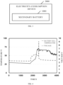
FIG. 2 is a schematic view of a battery according to an embodiment. -
FIG. 3 is a schematic view of an electricity-consumption device according to an embodiment. -
FIG. 4 is an overcharge curve of a secondary battery of graphite according toembodiment 1. -
FIG. 5 is an overcharge curve of a secondary battery of graphite according to comparative embodiment 2. - The following will clearly and completely describe technical solutions for embodiments of the present disclosure with reference to accompanying drawings. Apparently, embodiments described herein are merely some of, rather than all the embodiments of the present disclosure. Based on the embodiments of the present disclosure, all other embodiments obtained by those of ordinary skill in the art without creative effort shall fall in the scope of protection of the present disclosure.
- It may be noted that when a component is "fixed" to another component, the component may be fixed to the other component directly or via an intermediate component. When a component is "connected" to another component, the component may be connected to the other component directly or via an intermediate component.
- Unless otherwise defined, all technical and scientific terms used herein have the same meaning as commonly understood by those skilled in the art of the present disclosure. The terms used herein in the present disclosure are for the purpose of describing embodiments only and are not intended to limit the present disclosure. The term "and/or" used herein includes any and all combinations of one or more of associated listed items.
- In related researches, there have been many researches on thermal management of a positive electrode of the battery. However, currently, in terms of a carbon material negative electrode (especially, a graphite negative electrode), researches on exothermic characteristics and exothermic indexes of the battery remains unclear. Therefore, how to provide a safe negative active material that can reduce occurrence of the thermal runaway becomes a critical issue.
- The present disclosure is intended to provide a
negative electrode sheet 100, abattery 1000, and an electricity-consumption device 2000, so as to reduce occurrence of thermal runaway of thenegative electrode sheet 100 during operation. - In order to achieve the purpose of the present disclosure, the present disclosure provides the following technical solutions.
- Some embodiments of the present disclosure will be described in detail below with reference to the accompanying drawings. The following embodiments and characteristics in the embodiments may be combined with each other without conflict.
- A
negative electrode sheet 100 is provided in the present disclosure. As illustrated inFIG. 1 , thenegative electrode sheet 100 includes acurrent collector 20 and a negativeactive material layer 10 disposed on thecurrent collector 20. The negativeactive material layer 10 includes a negativeactive material 11. The negativeactive material layer 10 has a preset exothermic characteristic under preset conditions. The negativeactive material layer 10 with the preset exothermic characteristic can greatly improve high-temperature stability of thenegative electrode sheet 100. - Specifically, when a state of charge (SOC) of a battery with the
negative electrode sheet 100 is 100% or a voltage of the battery is 3.65V, a differential scanning calorimeter (DSC) curve of the negative active material layer includes a first exothermic peak, a second exothermic peak, and a third exothermic peak. The DSC curve of the negative active material layer in an immersed electrolyte is a heat release curve of the negative active material layer obtained by a DSC through measurement. - In an embodiment, the preset conditions include but are not limited to a particle diameter and/or a specific surface area of the negative active material.
- In an embodiment, the negative active material layer further includes a binder and a conductive agent. The negative active material, the conductive agent, and the binder are added to a solvent and mixed to prepare a negative electrode slurry, and then the negative electrode slurry is coated on the negative electrode
current collector 20 to prepare thenegative electrode sheet 100. - In an embodiment, the negative electrode current collector may be one or more of a copper foil, a porous copper foil, a foamed nickel/copper foil, a galvanized copper foil, a nickel-plated copper foil, a coated-carbon copper foil, a nickel foil, a titanium foil, and a carbonaceous porous copper foil. In an embodiment, the negative electrode current collector may be one or more of the copper foil, the galvanized copper foil, the nickel-plated copper foil, and the carbon-coated copper foil.
- In an embodiment, the binder may be acrylonitrile, vinylidene fluoride, vinyl alcohol, carboxymethyl cellulose, lithium carboxymethyl cellulose, sodium carboxymethyl cellulose, methacryloyl, acrylic acid, lithium acrylate, acrylamide, amide, imide, acrylate, styrene-butadiene rubber, sodium alginate, chitosan, ethanediol, guar gum monomer, polymer, or copolymer.
- In an embodiment, the conductive agent may be at least one of conductive carbon black, acetylene black, graphite, graphene, carbon micro-nano linear conductive material, or carbon micro-nano tubular conductive material.
- A specific DSC method for testing the negative active material layer is as follows. A fully-charged battery is disassembled in a glove box, to obtain a negative electrode sheet. The negative electrode sheet is cut into 2 cm*2 cm sample electrode sheets to be tested, and the sample electrode sheets to be tested are rinsed with dimethyl carbonate (DMC) for 3 minutes and dried at room temperature in the glove box for 8 hours, to obtain a negative active material on the dried sample electrode sheets to be tested. 3 mg of the negative active material is put into a crucible of a DSC, 2 mg of electrolyte is added to the crucible, and then the crucible is sealed and waited for testing. A condition for the DSC test is set to increase the temperature from 30 °C to 450 °C at a heating rate of 5 °C/min. The test is completed and a test result is obtained.
- In an embodiment, the crucible is gold-plated.
- In an embodiment, the electrolyte is formed by mixing ethylene carbonate (EC) and ethyl methyl carbonate (EMC) at a volume ratio of 3:7 and adding lithium hexafluorophosphate (LiPF6) to the mixture, where the LiPF6 has a concentration of 1 mol/L.
- The DSC can measure a heat-flow-power difference between a sample and a reference with changes in temperature or time under control of a certain temperature program (ascending/descending/constant temperature) and under a certain atmosphere. Based on this, information related to thermal effects such as heat absorption, heat release, and specific heat changes of the sample under the control of the temperature program can be obtained, and the heat absorption/release (enthalpy) and characteristic temperature (a starting point, a peak value, and an ending point) of the thermal effects can be calculated.
- Further, the first exothermic peak appears from 120 °C to 150 °C, the second exothermic peak appears from 220 °C to 260 °C, and the third exothermic peak appears from 260 °C to 310 °C. For example, an apex of the first exothermic peak may be in the temperature range from 120 °C to 150 °C, and an apex of an exothermic peak refers to a maximum point of the exothermic peak in a corresponding temperature range.
- The first exothermic peak actually corresponds to an exothermic peak of reaction of an outer SEI. It can be understood that the SEI is formed during a first charging and discharging process of the battery, and the SEI is a passivation film formed on the surface of the negative active material by active ions (lithium-ions or sodium-ions) and the solvent (EC/DMC). Therefore, the first exothermic peak is actually heat release before the SEI is broken. In the present disclosure, heat release corresponding to the SEI can be obtained by integrating the exothermic peak within the range from 120 °C to 150 °C in a DSC test spectrum, where a unit of the heat release is Joule (J).
- The second exothermic peak corresponds to an exothermic peak of reaction between the negative active material and the electrolyte. It can be understood that in the present disclosure, a negative active material in a fully-charged state is provided for the DSC test, and the negative active material is in direct contact with the electrolyte after the SEI is broken, so that the reaction between the negative active material and the electrolyte is intensified, and a large amount of heat is released.
- The third exothermic peak corresponds to an exothermic peak of reaction between the negative active material and the binder. It can be understood that after the reaction between the negative active material and the electrolyte is completed, the electrolyte is consumed, so that the negative active material further reacts with the binder attached to the surface of the negative active material, thereby releasing heat.
- In an embodiment, the first exothermic peak appears from 120 °C to 150 °C, in which the negative active material layer has heat release A1 satisfying 2 J/g≤A1≤50 J/g. In an embodiment, the heat release A1 may be, but is not limited to, 2 J/g, 10 J/g, 15 J/g, 20 J/g, 25 J/g, 30 J/g, 35 J/g, 40 J/g, 45 J/g, or 50 J/ g.
- It can be seen from the embodiment above that the heat release A1 corresponding to the first exothermic peak actually reflects the heat release generated before the SEI is broken. At the same time, the heat release generated before the SEI is broken is proportional to a content of the SEI. In other words, a thicker SEI causes a higher exothermic peak in the DSC curve, or a higher heat release obtained represents a higher content of the SEI in a negative active material to be tested.
- Therefore, the heat release corresponding to the first exothermic peak is controlled within the above range, so that the content of the SEI generated on the negative active material can be ensured to be within an appropriate range, thereby balancing electrochemical performance of the battery. If the heat release A1 corresponding to the first exothermic peak is below the above range, it indicates that the negative active material has a relatively low content of the SEI, so that side reaction is prone to occur between the active ions in the negative active material and the electrolyte and dead lithium (inactive alkali metal ion) in the negative active material is too much, which will affect capacity and cycle life of the battery. If the heat release A1 corresponding to the first exothermic peak is above the above range, it indicates that the negative active material has a relatively high content of the SEI, so that a large amount of active ions is consumed in a first cycle. In this case, the capacity of the battery is reduced, and an interface of the negative active material is extremely unstable, so that thermal runaway is easily aggravated.
- In an embodiment, the second exothermic peak appears from 220 °C to 260 °C, in which the negative active material layer has heat release A2 satisfying 20 J/g≤A2≤ 100 J/g. In an embodiment, the heat release A2 may be, but is not limited to, 20 J/g, 30 J/g, 40 J/g, 50 J/g, 60 J/g, 70 J/g, 80 J/g, 90 J/g, or 100 J/g.
- It can be seen from the embodiment above that the heat release A2 corresponding to the second exothermic peak actually reflects the heat release generated during the reaction between the negative active material and the electrolyte. The heat release A2 can reflect intensity of the reaction between the negative active material and the electrolyte. In other words, stronger reaction between the negative active material and the electrolyte causes a higher exothermic peak in the DSC curve, or higher heat release obtained represents poorer thermal stability of the negative active material.
- Therefore, the heat release corresponding to the second exothermic peak is controlled within the above range, so that the negative active material can be ensured to have strong thermal stability in the electrolyte, thereby balancing the electrochemical performance of the battery and avoiding the thermal runaway. If the heat release A2 corresponding to the second exothermic peak is below the above range, it indicates that the reaction between the negative active material and the electrolyte is relatively weak and dead lithium (inactive alkali metal ion) is too much, so that the battery capacity is poor. If the heat release A2 corresponding to the second exothermic peak is above the above range, it indicates that the reaction between the negative active material and the electrolyte is relatively strong and overall reactivity of a lithiated negative active material is relatively high, so that the thermal runaway is easily aggravated.
- In an embodiment, the third exothermic peak appears from 260 °C to 310 °C, in which the negative active material layer has heat release A3 satisfying 200 J/g≤A3≤600 J/g. In an embodiment, the heat release A3 may be, but is not limited to, 200 J/g, 250 J/g, 300 J/g, 350 J/g, 400 J/g, 450 J/g, 500 J/g, 550 J/g, or 600 J/g.
- It can be seen from the embodiment above that the heat release A3 corresponding to the third exothermic peak actually reflects the heat release generated during the reaction between the negative active material and the binder. The heat release A3 can reflect intensity of the reaction between the negative active material and the binder. In other words, stronger reaction between the negative active material and the binder causes a higher exothermic peak in the DSC curve, or higher heat release obtained represents poorer thermal stability of the negative active material.
- Therefore, the heat release corresponding to the third exothermic peak is controlled within the above range, so that the negative active material can be ensured to have strong thermal stability with the binder, thereby balancing the electrochemical performance of the battery and avoiding the thermal runaway. If the heat release A3 corresponding to the third exothermic peak is below the above range, it indicates that the reaction between the negative active material and the binder is relatively weak and dead lithium (inactive alkali metal ion) is too much, so that the battery capacity is poor. If the heat release A3 corresponding to the third exothermic peak is above the above range, it indicates that the reaction between the negative active material and the binder is relatively strong and the overall reactivity of the lithiated negative active material is relatively high, so that the thermal runaway is easily aggravated.
- The negative active material satisfying the above relationship can significantly improve high-temperature stability of the negative electrode sheet with the negative active material. In this way, an assembled battery can be ensured to maintain relatively low heat release in three different heat release stages under a high-temperature operating environment, so that relatively high heat release due to excessive temperature can be avoided in the three heat release stages, and the thermal runaway can be avoided. For the negative active material satisfying the above relationship, heat release in each temperature range is controlled within a range that the battery can tolerate, so that the battery will not spontaneously combust or explode due to excessive heat, which means that the negative electrode sheet has excellent high-temperature stability.
- In an embodiment, peak shapes of the first exothermic peak, the second exothermic peak, and the third exothermic peak include one or any combination of a single characteristic peak shape, a double shoulder peak shape, or a continuous peak shape.
- In an embodiment, the heat release A1 corresponding to the first exothermic peak and the heat release A3 corresponding to the third exothermic peak satisfy: 0.003≤A1/A3≤ 0.25. In an embodiment, A1/A3 may be, but are not limited to, 0.003, 0.01, 0.02, 0.05, 0.07, 0.1, 0.12, 0.14, 0.18, 0.2, 0.23, or 0.25.
- If A1/A3 is less than 0.003, it indicates that the active ions are not active enough and the battery life will be affected. If A1/A3 is greater than 0.25, it indicates that the SEI is too thick and extremely unstable, and the SEI is prone to be broken to generate a large amount of heat, so that the thermal runaway is more likely to occur.
- In an embodiment, the heat release A2 corresponding to the second exothermic peak and the heat release A3 corresponding to the third exothermic peak satisfy: 0.03 ≤A2/A3 ≤0.5. In an embodiment, A2/A3 may be, but is not limited to, 0.03, 0.04, 0.05, 0.06, 0.08, 0.1, 0.15, 0.2, 0.25, 0.3, 0.35, 0.4, or 0.5.
- If A2/A3 is less than 0.03, it indicates that the active ions are not active enough and the battery life will be affected. If A2/A3 is greater than 0.5, it indicates that the reaction between the negative active material and the electrolyte is strong and a large amount of heat is generated, so that the thermal runaway is triggered.
- In an embodiment, a particle diameter Dv50 of the negative active material satisfies 10 µm≤Dv50≤ 17 µm, where the Dv50 refers to a particle diameter when a cumulative volume fraction reaches 50% in measuring a volume-based distribution using a laser scattering method.
- The Dv50 may be measured as follows. According to a GB/T19077-2016 standard, a graphite particle is sampled and measured by a laser-diffraction particle size distribution analyzer (Malvern Mastersizer 3000).
- In an embodiment, the particle diameter Dv50 of the negative active material may be, but is not limited to, 10 µm, 11 µm, 12 µm, 13 µm, 14 µm, 15 µm, 16 µm, or 17 µm.
- Further, in addition to controlling the heat release corresponding to the negative active material, the particle diameter of the negative active material further needs to be controlled, so that the negative active material is not too large or too small. Since an excessively small negative active material has a relatively large specific surface area, the reactivity between the electrolyte and the negative active material increases, so that side reaction between the negative active material layer and the electrolyte is aggravated and heat accumulation is caused, thereby leading to thermal runaway.
- By further limiting a particle diameter of the negative active material, heat generated by reaction between the negative active material and the electrolyte can be further reduced by controlling the particle diameter while controlling the heat release, so that the negative active material can be ensured to have relatively high thermal stability.
- If the particle diameter of the negative active material is below the above range, it indicates that the negative active material in the negative active material layer has a relatively small particle diameter, which not only easily causes a lot of side reactions but also increases preparation difficulty of the negative active material. In this case, the negative active material is easily agglomerated and difficultly subdivided. When the particle diameter of the negative active material is above the above range, the particle is too large, so that storage sites of alkali metal ions decrease and capacity of the battery is relatively poor.
- In an embodiment, the specific surface area of the negative active material satisfies 1.1 m2/g to 4.5 m2/g. Specifically, the specific surface area of the negative active material may be, but is not limited to, 1.1 m2/g, 1.15 m2/g, 1.2 m2/g, 1.25 m2/g, 1.3 m2/g, 1.35 m2/g, 1.4 m2/g, or 4.5 m2/g.
- Since the specific surface area will affect initial coulombic efficiency (ICE) of the negative active material and deintercalation of the active ions, a larger specific surface area causes lower ICE, smaller specific surface area is not conducive to the deintercalation of the active ions, and the specific surface area of the negative active material maintained within the above range can ensure that the negative active material can have excellent electrochemical performance.
- In an embodiment, a gram capacity of the negative active material ranges from 330 mAh/g to 360 mAh/g. Specifically, the gram capacity of the negative active material may be, but is not limited to, 330 mAh/g, 340 mAh/g, 341 mAh/g, 342 mAh/g, 343 mAh/g, 344 mAh/g, 345 mAh/g, 346 mAh/g, 347 mAh/g, 348 mAh/g, 349 mAh/g, 350 mAh/g, or 360 mAh/g.
- In an embodiment, the negative active material is one or more of a graphite particle, a soft carbon particle, or a hard carbon particle.
- The graphite particle may be natural graphite or artificial graphite, which is not limited in the present disclosure. A shape of the graphite particle is not limited and may be spherical, plate-shaped, etc. A graphite material is the most widely used negative active material. The graphite material has good conductivity, which can not only improve conductivity of a silicon material but also increase capacity.
- In an embodiment, the negative active material may be one or more of negative active materials that are subject to: surface treatments such as spheroidization or structural modification, oxidation, etching, etc.; or doping with nitrogen, phosphorus, sulfur, iron, cobalt, nickel, aluminum, zinc, or the like; or modification treatments such as being coated with an amorphous carbon layer, etc.
- In an embodiment, a
battery 1000 is further provided in the present disclosure. As illustrated inFIG. 2 , thebattery 1000 includeselectrolyte 400, apositive electrode sheet 200, aseparator 300, and thenegative electrode sheet 100 of the first aspect. Thepositive electrode sheet 200 is at least partially immersed in theelectrolyte 400. Theseparator 300 is located at one side of thepositive electrode sheet 200 and is at least partially immersed in theelectrolyte 400. Thenegative electrode sheet 100 is disposed at one side of theseparator 300 away from thepositive electrode sheet 200 and at least partially immersed in theelectrolyte 400. Since thebattery 1000 provided in the present disclosure adopts thenegative electrode sheet 100 provided in the present disclosure, thebattery 1000 has good high-temperature stability and safety, thereby facilitating application of the battery in various fields. - In an embodiment, as illustrated in
FIG. 3 , an electricity-consumption device 2000 is further provided in the present disclosure. The electricity-consumption device 2000 includes thebattery 1000 described above. The electricity-consumption device 2000 adopting thebattery 1000 can have high-temperature stability. - Technical solutions of the present disclosure will be further described below with reference to embodiments and accompanying drawings.
- Preparation of a graphite particle is as follows. A coke raw material is crushed, graphitized, screened and demagnetized, etc., and then artificial graphite is obtained. The artificial graphite has a particle diameter distribution of Dv50=16.5 µm, a specific surface area of 1.21 m2/g, and heat release A1 of 2.2 J/g, A1/A3=0.005, and A2/A3=0.05. A negative active material layer is prepared with the graphite particle.
- Preparation of a graphite particle is as follows. A coke raw material is crushed, graphitized, screened and demagnetized, etc., and then artificial graphite is obtained. The artificial graphite has a particle diameter distribution of Dv50=15.8 µm, a specific surface area of 1.34 m2/g, and heat release A1 of 2.8 J/g, A1/A3=0.006, and A2/A3=0.06. A negative active material layer is prepared with the graphite particle.
- Preparation of a graphite particle is as follows. A coke raw material is crushed, graphitized, screened and demagnetized, etc., and then artificial graphite is obtained. The artificial graphite has a particle diameter distribution of Dv50=14.9 µm, a specific surface area of 1.38 m2/g, and heat release A1 of 3.2 J/g, A1/A3=0.006, and A2/A3=0.09. A negative active material layer is prepared with the graphite particle.
- Preparation of a graphite particle is as follows. A coke raw material is crushed, graphitized, screened and demagnetized, etc., and then artificial graphite is obtained. The artificial graphite has a particle diameter distribution of Dv50=13.2 µm, a specific surface area of 1.54 m2/g, and heat release A1 of 4.1 J/g, A1/A3=0.008, and A2/A3=0.15. A negative active material layer is prepared with the graphite particle.
- Preparation of a graphite particle is as follows. A coke raw material is crushed, graphitized, screened and demagnetized, etc., and then artificial graphite is obtained. The artificial graphite has a particle diameter distribution of Dv50=12.5 µm, a specific surface area of 1.63 m2/g, and heat release A1 of 4.5 J/g, A1/A3=0.009, and A2/A3=0.19. A negative active material layer is prepared with the graphite particle.
- Preparation of a graphite particle is as follows. A coke raw material is crushed, graphitized, screened and demagnetized, etc., and then artificial graphite is obtained. The artificial graphite has a particle diameter distribution of Dv50=11.2 µm, a specific surface area of 1.65 m2/g, and heat release A1 of 5.2 J/g, A1/A3=0.0029, and A2/A3=0.52. A negative active material layer is prepared with the graphite particle.
- Preparation of a graphite particle is as follows. A coke raw material is crushed, graphitized, screened and demagnetized, etc., and then artificial graphite is obtained. The artificial graphite has a particle diameter distribution of Dv50=10.2 µm, a specific surface area of 1.97 m2/g, and heat release A1 of 6.31 J/g, A1/A3=0.0025, and A2/A3=0.54. A negative active material layer is prepared with the graphite particle.
- Preparation of a graphite particle is as follows. A coke raw material is crushed, graphitized, screened and demagnetized, etc., and then artificial graphite is obtained. The artificial graphite has a particle diameter distribution of Dv50=17.2 µm, a specific surface area of 1.24 m2/g, and heat release A1 of 1.31 J/g, A1/A3=0.002, and A2/A3=0.025. A negative active material layer is prepared with the graphite particle.
- The negative active material provided in each of
embodiments 1 to 5 and the negative active material provided in one of thecomparative embodiments 1 to 3 may be assembled into a negative electrode sheet and a lithium-ion secondary battery in the following methods. - Positive electrode: a positive electrode material is mixed and ball-milled with polyvinylidene fluoride and Super-P (i.e., conductive carbon black) at a mass ratio of 93:3:4 to obtain a positive electrode slurry. The positive electrode slurry is coated on a surface of an aluminum foil, is vacuum dried at 110 °C overnight, and is rolled to obtain a positive electrode sheet.
- Negative electrode: a negative active material is configured with conductive carbon black, carboxymethyl cellulose (CMC), and styrene-butadiene rubber (SBR) at a mass ratio of 95%:2%: 1.2%: 1.8% to obtain a negative electrode slurry. The negative electrode slurry is evenly coated on an aluminum foil to obtain a negative electrode sheet.
- Electrolyte: EC is mixed with EMC at a volume ratio of 3:7, and LiPF6 is added thereto, so as to form the electrolyte. LiPF6 has a concentration of 1 mol/L.
- Separator: a polypropylene microporous separator.
- Assembling of a lithium-ion secondary battery: a lithium-ion full battery is assembled in an inert-atmosphere glove box in an order of the negative electrode sheet-the separator-the electrolyte-the positive electrode sheet.
- Conditions for cycle tests: the above battery obtained is subject to charging and discharging cycle tests on a charging and discharging instrument. Test temperature is 25 °C, cycle rate is 1C (i.e., both a charging rate and a discharging rate are 1C), a charging voltage ranges from 2.5V to 3.65V, and capacity retention rate after cycles is calculated. A formula for calculating the capacity retention rate of the cycles is: capacity retention rate after nth cycles = (discharging capacity after the nth cycles/maximum discharging capacity of the cycles) * 100%.
- It can be understood that a term "cycle" in the present disclosure refers to the number of times the battery is charged at preset rate and discharged at the preset rate. One cycle refers to completion of one charging and discharging process by the battery. Capacity retention rate after 500 cycles refers to the capacity retention rate of the battery after 500 cycles of the charging and discharging process at a test temperature of 25 °C, a charging rate of 1C, and a discharging rate of 1C.
- The electrochemical performance of each lithium-ion secondary battery assembled in the above lithium-ion secondary battery embodiments is tested in terms of performances as shown in Table 1, and test results are as shown in Table 1 below.
Table 1 Dv50 particle diameter (µm) Specific surface area (m2/g) Gram capacity (mAh/g) A1/A3 A1/A2 Retention rate after 500 cycles (%) Whether overcharge is passed Embodiment 116.5 1.21 348 0.005 0.05 95.2 YES Embodiment 2 15.8 1.34 346 0.006 0.06 94.3 YES Embodiment 3 14.9 1.38 345 0.006 0.09 92.7 YES Embodiment 4 13.2 1.54 344 0.008 0.15 91.8 YES Embodiment 5 12.5 1.63 344 0.009 0.19 91.2 YES Comparative embodiment 1 11.2 1.65 343 0.0029 0.52 90.2 NO Comparative embodiment 2 10.2 1.97 342 0.0025 0.54 86.3 NO Comparative embodiment 317.2 1.24 343 0.002 0.025 85.2 NO - As can be seen from the
embodiments 1 to 5, a battery assembled with the negative active material with the heat release provided in the present disclosure still can have relatively high cycle retention rate after multiple cycles. When the negative active material is used in a long-term high-temperature environment, the heat release corresponding to the negative active material in the three heat release stages is within the ranges provided in the present disclosure, and the heat release has a relatively small impact on the overall electrical performance of the battery. Therefore, the retention rate after 500 cycles of the battery can reach more than 90%. - As can be seen from the
comparative embodiments 1 to 3, when any heat release of the carbon material in the three heat release stages does not satisfy the range provided in the present disclosure (any range of A1, A2, and A3), the ratio of A1/A3 or A2/A3 will become unbalanced. Therefore, the retention rate after 500 cycles of the battery is less than that of theembodiments 1 to 5. Moreover, while the heat release of the material tested in thecomparative embodiment 3 is low, the material will lead to severe lithium precipitation during an overcharge process due to poor dynamics performance of the material, thereby triggering the thermal runaway. - Further,
FIG. 4 illustrates an overcharge curve of a secondary battery ofgraphite embodiment 1. In a case where an overcharge voltage reaches 5.475V, the battery stops being charged and keeps still. In this case, a voltage of the battery cell can still maintain an initial voltage, and temperature of the battery cell is relatively low (about 53 °C), which indicates that the secondary battery provided in theembodiment 1 passes an overcharge test. -
FIG. 5 illustrates an overcharge curve of a secondary battery of graphite comparative embodiment 2. In a case where an overcharge voltage reaches 5.475V, the battery stops being charged and keeps still. In this case, a voltage of the battery cell drops to 0V, temperature of the battery cell increases to 253 °C, so that the thermal runaway is triggered, which indicates that the secondary battery provided in the comparative embodiment 2 fails an overcharge test. - In description of the present disclosure, it may be understood that locations or positional relationships indicated by terms such as "center", "on", "under", "left", "right", "vertical", "horizontal", "in", "out", and the like are locations or positional relationship based on accompanying drawings and are only for the convenience of description and simplicity, rather than explicitly or implicitly indicate that apparatuses or components referred to herein must have a certain direction or be configured or operated in a certain direction and therefore cannot be understood as limitations to the present disclosure.
- The above embodiments are only preferable embodiments of the present disclosure, of course, the above embodiments cannot be used to limit the scope of this disclosure, the ordinary skill in the field can understand all or a part of the process to realize the above embodiments of the present disclosure, and the equivalent changes made in accordance with the claims of this disclosure, still belong to the scope of the present disclosure covered.
Claims (11)
- A negative electrode sheet (100), comprising a current collector (20) and a negative active material layer (10) disposed on the current collector (20), wherein the negative active material layer (10) comprises a negative active material (11), and when a state of charge (SOC) of a battery with the negative electrode sheet (100) is 100% or a voltage of the battery is 3.65V, a differential scanning calorimeter (DSC) curve of the negative active material layer (10) comprises:a first exothermic peak from 120 °C to 150 °C, in which the negative active material layer (10) has heat release A1 satisfying 2 J/g≤A1≤50 J/g;a second exothermic peak from 220 °C to 260 °C, in which the negative active material layer (10) has heat release A2 satisfying 20 J/g≤A2≤ 100 J/g; anda third exothermic peak from 260 °C to 310 °C, in which the negative active material layer (10) has heat release A3 satisfying 200 J/g≤A3≤600 J/g.
- The negative electrode sheet (100) of claim 1, wherein the DSC curve of the negative active material layer (10) is obtained by a DSC through measurement, and the measurement is performed by adding the negative active material layer (10) and electrolyte into a gold-plated crucible at a mass ratio of 0.78:1 and heating the gold-plated crucible from 30 °C to 450 °C at a heating rate of 5 °C/min.
- The negative electrode sheet (100) of claim 1, wherein peak shapes of the first exothermic peak, the second exothermic peak, and the third exothermic peak comprise one or any combination of a single characteristic peak shape, a double shoulder peak shape, or a continuous peak shape.
- The negative electrode sheet (100) of claim 1, wherein the heat release A1 corresponding to the first exothermic peak and the heat release A3 corresponding to the third exothermic peak satisfy: 0.003≤A1/A3≤0.25.
- The negative electrode sheet (100) of claim 1, wherein the heat release A2 corresponding to the second exothermic peak and the heat release A3 corresponding to the third exothermic peak satisfy: 0.03 ≤A2/A3≤0.5.
- The negative electrode sheet (100) of claim 1, wherein a particle diameter Dv50 of the negative active material (11) satisfies 10 µm≤Dv50≤ 17 µm, wherein the Dv50 refers to a particle diameter when a cumulative volume fraction reaches 50% in measuring a volume-based distribution using a laser scattering method.
- The negative electrode sheet (100) of claim 1, wherein the specific surface area of the negative active material (11) satisfies 1.1 m2/g to 4.5 m2/g.
- The negative electrode sheet (100) of claim 1, wherein a gram capacity of the negative active material (11) ranges from 330 mAh/g to 360 mAh/g.
- The negative electrode sheet (100) of claim 1, wherein the negative active material (11) is one or more of a graphite particle, a soft carbon particle, or a hard carbon particle.
- A battery (1000), comprising:electrolyte (400);a positive electrode sheet (2000) at least partially immersed in the electrolyte;a separator (300) located at one side of the positive electrode sheet and at least partially immersed in the electrolyte; andthe negative electrode sheet (100) of any of claims 1 to 9, wherein the negative electrode sheet (100) is disposed at one side of the separator (300) away from the positive electrode sheet (2000) and at least partially immersed in the electrolyte (400).
- An electricity-consumption device (2000), comprising the battery of claim 10.
Applications Claiming Priority (1)
| Application Number | Priority Date | Filing Date | Title |
|---|---|---|---|
| CN202310922205.4A CN116666565B (en) | 2023-07-26 | 2023-07-26 | Negative electrode plates, batteries and electrical equipment |
Publications (2)
| Publication Number | Publication Date |
|---|---|
| EP4498445A2 true EP4498445A2 (en) | 2025-01-29 |
| EP4498445A3 EP4498445A3 (en) | 2025-04-23 |
Family
ID=87722731
Family Applications (1)
| Application Number | Title | Priority Date | Filing Date |
|---|---|---|---|
| EP24182790.6A Pending EP4498445A3 (en) | 2023-07-26 | 2024-06-18 | Negative electrode sheet, battery, and electricity-consumption device |
Country Status (3)
| Country | Link |
|---|---|
| US (1) | US20250038204A1 (en) |
| EP (1) | EP4498445A3 (en) |
| CN (1) | CN116666565B (en) |
Families Citing this family (1)
| Publication number | Priority date | Publication date | Assignee | Title |
|---|---|---|---|---|
| CN117855649A (en) * | 2023-11-24 | 2024-04-09 | 厦门海辰储能科技股份有限公司 | Batteries, energy storage devices, power systems and energy storage systems |
Family Cites Families (11)
| Publication number | Priority date | Publication date | Assignee | Title |
|---|---|---|---|---|
| JP4883025B2 (en) * | 2007-10-31 | 2012-02-22 | ソニー株式会社 | Secondary battery |
| KR101124893B1 (en) * | 2010-06-21 | 2012-03-27 | 지에스칼텍스 주식회사 | Anode active material improved safety and secondary battery employed with the same |
| CN103311521B (en) * | 2012-03-07 | 2016-12-14 | 上海杉杉科技有限公司 | A kind of surface modified graphite negative material and its production and use |
| CN108844878A (en) * | 2018-05-24 | 2018-11-20 | 宁德时代新能源科技股份有限公司 | Negative pole piece, method for testing active specific surface area of pole piece and battery |
| CN109841831B (en) * | 2019-03-21 | 2020-12-25 | 宁德新能源科技有限公司 | Negative electrode material, negative electrode comprising same, and electrochemical device |
| CN112447964B (en) * | 2019-09-02 | 2022-04-19 | 宁德时代新能源科技股份有限公司 | Positive electrode active material, positive electrode plate and lithium ion secondary battery |
| CN111426724B (en) * | 2019-10-23 | 2022-08-19 | 蜂巢能源科技有限公司 | Method for testing safety performance of electrode material |
| CN114384112B (en) * | 2020-10-22 | 2024-09-17 | 清华大学 | A method for detecting SEI film on the surface of lithium-ion battery electrode |
| WO2022162950A1 (en) * | 2021-02-01 | 2022-08-04 | 昭和電工マテリアルズ株式会社 | Negative electrode material for lithium-ion secondary battery, method for evaluating negative electrode material, method for manufacturing same, negative electrode for lithium-ion secondary battery, and lithium-ion secondary battery |
| CN113078292B (en) * | 2021-03-29 | 2022-08-19 | 宁德新能源科技有限公司 | Negative electrode, electrochemical device comprising same and electronic device |
| CN114156446B (en) * | 2021-11-11 | 2024-09-06 | 珠海冠宇电池股份有限公司 | Negative electrode active material, negative electrode sheet containing the negative electrode active material, and lithium ion battery |
-
2023
- 2023-07-26 CN CN202310922205.4A patent/CN116666565B/en active Active
-
2024
- 2024-06-18 EP EP24182790.6A patent/EP4498445A3/en active Pending
- 2024-06-27 US US18/757,061 patent/US20250038204A1/en active Pending
Also Published As
| Publication number | Publication date |
|---|---|
| CN116666565A (en) | 2023-08-29 |
| CN116666565B (en) | 2024-02-09 |
| EP4498445A3 (en) | 2025-04-23 |
| US20250038204A1 (en) | 2025-01-30 |
Similar Documents
| Publication | Publication Date | Title |
|---|---|---|
| US12300816B2 (en) | Positive electrode active material, positive electrode plate, lithium-ion secondary battery, and apparatus | |
| CN101515640B (en) | Cathode and lithium ion secondary battery containing same | |
| KR20210038501A (en) | Positive electrode active material for lithium secondary battery and lithium secondary battery comprising the same | |
| US20110135982A1 (en) | Negative electrode for non-aqueous electrolyte secondary battery and fabrication method thereof, and non-aqueous electrolyte secondary battery | |
| JP2023506034A (en) | Positive electrode for lithium secondary battery, lithium secondary battery comprising said positive electrode | |
| CN114464774A (en) | A kind of negative pole piece and its application | |
| JP3529750B2 (en) | Non-aqueous electrolyte secondary battery | |
| CN108493419B (en) | A kind of temperature sensitive composite electrode and preparation method thereof | |
| CN115528208B (en) | A lithium-supplemented negative electrode sheet and a secondary battery | |
| WO2021108987A1 (en) | Composite graphite material, secondary battery, device, and preparation method | |
| US20250132339A1 (en) | Secondary battery and electronic apparatus | |
| KR20240137677A (en) | Separator and its manufacturing method, secondary battery and electric device | |
| WO2025201024A1 (en) | Secondary battery, manufacturing method therefor and electronic apparatus | |
| EP4498445A2 (en) | Negative electrode sheet, battery, and electricity-consumption device | |
| EP4517862A1 (en) | Negative electrode sheet, secondary battery, and electricity-consumption device | |
| EP2631973B1 (en) | Electrode for lithium secondary battery, manufacturing method thereof and lithium secondary battery comprising the same | |
| CN101110477B (en) | An electrochemical energy storage and energy conversion device | |
| JP3111927B2 (en) | Non-aqueous electrolyte secondary battery and method of manufacturing the same | |
| CN120380630A (en) | Lithium secondary battery and electricity utilization device | |
| CN118435374A (en) | Electrode plate, secondary battery and electricity utilization device | |
| JP2004227931A (en) | Non-aqueous electrolyte secondary battery | |
| KR102812316B1 (en) | Positive electrode active material coated with lithium molybdenum compound for lithium secondary battery and method for manufacturing the same | |
| US12191523B2 (en) | Polymer-modified porous material, membrane electrode, secondary battery, and electric device | |
| US20250006889A1 (en) | Negative electrode and electrochemical apparatus and electronic apparatus using same | |
| WO2025086649A1 (en) | Negative electrode active material, negative electrode sheet, sodium ion battery, and electric device |
Legal Events
| Date | Code | Title | Description |
|---|---|---|---|
| PUAI | Public reference made under article 153(3) epc to a published international application that has entered the european phase |
Free format text: ORIGINAL CODE: 0009012 |
|
| STAA | Information on the status of an ep patent application or granted ep patent |
Free format text: STATUS: THE APPLICATION HAS BEEN PUBLISHED |
|
| AK | Designated contracting states |
Kind code of ref document: A2 Designated state(s): AL AT BE BG CH CY CZ DE DK EE ES FI FR GB GR HR HU IE IS IT LI LT LU LV MC ME MK MT NL NO PL PT RO RS SE SI SK SM TR |
|
| PUAL | Search report despatched |
Free format text: ORIGINAL CODE: 0009013 |
|
| RAP1 | Party data changed (applicant data changed or rights of an application transferred) |
Owner name: HITHIUM TECH HK LIMITED |
|
| AK | Designated contracting states |
Kind code of ref document: A3 Designated state(s): AL AT BE BG CH CY CZ DE DK EE ES FI FR GB GR HR HU IE IS IT LI LT LU LV MC ME MK MT NL NO PL PT RO RS SE SI SK SM TR |
|
| RIC1 | Information provided on ipc code assigned before grant |
Ipc: H01M 4/02 20060101ALN20250317BHEP Ipc: H01M 4/62 20060101ALN20250317BHEP Ipc: H01M 10/054 20100101ALI20250317BHEP Ipc: H01M 10/0525 20100101ALI20250317BHEP Ipc: H01M 4/587 20100101ALI20250317BHEP Ipc: H01M 4/36 20060101ALI20250317BHEP Ipc: H01M 4/133 20100101AFI20250317BHEP |
|
| STAA | Information on the status of an ep patent application or granted ep patent |
Free format text: STATUS: REQUEST FOR EXAMINATION WAS MADE |
|
| 17P | Request for examination filed |
Effective date: 20251022 |
|
| RIC1 | Information provided on ipc code assigned before grant |
Ipc: H01M 4/133 20100101AFI20260123BHEP Ipc: H01M 4/36 20060101ALI20260123BHEP Ipc: H01M 4/587 20100101ALI20260123BHEP Ipc: H01M 10/0525 20100101ALI20260123BHEP Ipc: H01M 10/054 20100101ALI20260123BHEP Ipc: H01M 4/62 20060101ALN20260123BHEP Ipc: H01M 4/02 20060101ALN20260123BHEP |
|
| GRAP | Despatch of communication of intention to grant a patent |
Free format text: ORIGINAL CODE: EPIDOSNIGR1 |
|
| STAA | Information on the status of an ep patent application or granted ep patent |
Free format text: STATUS: GRANT OF PATENT IS INTENDED |
|
| INTG | Intention to grant announced |
Effective date: 20260310 |
|
| GRAS | Grant fee paid |
Free format text: ORIGINAL CODE: EPIDOSNIGR3 |
|
| GRAA | (expected) grant |
Free format text: ORIGINAL CODE: 0009210 |
|
| STAA | Information on the status of an ep patent application or granted ep patent |
Free format text: STATUS: THE PATENT HAS BEEN GRANTED |