EP4498345A2 - Live-status-benachrichtigung von antwortpersonalaktionen an gebäudebesitzer/-betreiber - Google Patents
Live-status-benachrichtigung von antwortpersonalaktionen an gebäudebesitzer/-betreiber Download PDFInfo
- Publication number
- EP4498345A2 EP4498345A2 EP24219585.7A EP24219585A EP4498345A2 EP 4498345 A2 EP4498345 A2 EP 4498345A2 EP 24219585 A EP24219585 A EP 24219585A EP 4498345 A2 EP4498345 A2 EP 4498345A2
- Authority
- EP
- European Patent Office
- Prior art keywords
- event
- communication device
- response
- events
- building
- Prior art date
- Legal status (The legal status is an assumption and is not a legal conclusion. Google has not performed a legal analysis and makes no representation as to the accuracy of the status listed.)
- Pending
Links
Images


Classifications
-
- G—PHYSICS
- G08—SIGNALLING
- G08B—SIGNALLING SYSTEMS, e.g. PERSONAL CALLING SYSTEMS; ORDER TELEGRAPHS; ALARM SYSTEMS
- G08B19/00—Alarms responsive to two or more different undesired or abnormal conditions, e.g. burglary and fire, abnormal temperature and abnormal rate of flow
-
- G—PHYSICS
- G08—SIGNALLING
- G08B—SIGNALLING SYSTEMS, e.g. PERSONAL CALLING SYSTEMS; ORDER TELEGRAPHS; ALARM SYSTEMS
- G08B27/00—Alarm systems in which the alarm condition is signalled from a central station to a plurality of substations
- G08B27/001—Signalling to an emergency team, e.g. firemen
-
- G—PHYSICS
- G08—SIGNALLING
- G08B—SIGNALLING SYSTEMS, e.g. PERSONAL CALLING SYSTEMS; ORDER TELEGRAPHS; ALARM SYSTEMS
- G08B25/00—Alarm systems in which the location of the alarm condition is signalled to a central station, e.g. fire or police telegraphic systems
- G08B25/01—Alarm systems in which the location of the alarm condition is signalled to a central station, e.g. fire or police telegraphic systems characterised by the transmission medium
- G08B25/04—Alarm systems in which the location of the alarm condition is signalled to a central station, e.g. fire or police telegraphic systems characterised by the transmission medium using a single signalling line, e.g. in a closed loop
-
- G—PHYSICS
- G08—SIGNALLING
- G08B—SIGNALLING SYSTEMS, e.g. PERSONAL CALLING SYSTEMS; ORDER TELEGRAPHS; ALARM SYSTEMS
- G08B25/00—Alarm systems in which the location of the alarm condition is signalled to a central station, e.g. fire or police telegraphic systems
- G08B25/01—Alarm systems in which the location of the alarm condition is signalled to a central station, e.g. fire or police telegraphic systems characterised by the transmission medium
- G08B25/08—Alarm systems in which the location of the alarm condition is signalled to a central station, e.g. fire or police telegraphic systems characterised by the transmission medium using communication transmission lines
-
- H—ELECTRICITY
- H04—ELECTRIC COMMUNICATION TECHNIQUE
- H04W—WIRELESS COMMUNICATION NETWORKS
- H04W4/00—Services specially adapted for wireless communication networks; Facilities therefor
- H04W4/12—Messaging; Mailboxes; Announcements
Definitions
- the present disclosure relates to devices, systems, and methods for live status notification of response personnel actions to building owner/operators.
- an alarm system may include a control panel (e.g., a fire control panel) within the building and a plurality of event devices (e.g., hazard sensing devices, such as fire detectors, smoke detectors, carbon monoxide detectors, carbon dioxide detectors, other harmful chemical detectors, audio-visual monitoring devices, etc.) located throughout the facility (e.g., on different floors and/or in different rooms of the facility) that can sense a hazard event occurring in the facility and provide a notification of the hazard event to the occupants of the facility via alarms or other mechanisms.
- hazard sensing devices such as fire detectors, smoke detectors, carbon monoxide detectors, carbon dioxide detectors, other harmful chemical detectors, audio-visual monitoring devices, etc.
- an alarm event signal reaches the central monitoring station, based on the type of alarm the monitoring personnel take appropriate actions and inform to authorized emergency responders. For example, in case of a fire alarm event signal, the personnel at the central monitoring station would call a fire station and inform them that a fire alarm event signal has been received from the alarm system of a facility. Or, in the case of a security breach the personnel would inform a nearby police department, etc.
- the actions that the central monitoring station personnel take are recorded in their central monitoring station system, but the progress that they are making to address the alarm is not known to the building owner/building facility manager.
- the progress actions like - informed emergency responders, emergency responders started to target location, emergency responders have reached the location, emergency responders are in action to suppress incident, emergency responders completed activities and have left the area, etc.
- These detailed actions are captured manually and the information is maintained in the central monitoring station system, but these in-between progress status details are not known to the building owner/building facility manager.
- the response personnel status system includes a communication link between the central station and a remote server (e.g., cloud server).
- a remote server e.g., cloud server
- in-between update data is data describing a status condition that is in between the event alarm signal and a signal that the event has been handled.
- Information provided can, for example, be: a type of incident happened (fire, chemical release, security situation), based on this incident the central station has performed a particular action, the current action being performed, the next action to be performed, the third action to be performed, among other information.
- the responding personnel can also receive information about the building that may not be available to the central monitoring station, such as the best door to enter, potential areas that may be dangerous (e.g., areas under construction), if a prior arranged path is still the preferred path or if an alternative path should be followed, etc.
- the building owner/operator can then return answers, for example, to the central monitoring station that can then be forwarded to the responding personnel (e.g., emergency response personnel, fire fighters, police officers, security personnel, etc.).
- Other information to be communicated can be floor of building or area specific.
- the building owner/operator can provide a number and/or location of fire extinguishers, a number and/or location of exits, live status updates of the building condition while the responders are in route (e.g., SW corner of building smoking, may be fully engulfed when you arrive, use entry point #2 as entry #1 may be on fire), among other relevant details.
- Information received from each party (building owner/operator, responder) can be taken in by the central monitoring center as spoken words and transcribed, for example, automatically by transcription software and then the text can be sent to the appropriate party (building owner/operator, responder).
- One system includes a building owner/operator communication device, an alarm system at a building having a control panel component and one or more alarm system device components, a central monitoring station configured to execute executable instructions to: receive an event alarm signal from an alarm system component, send a response request signal to a response facility, receive a response request signal reply indicating that response facility personnel will respond to the building, receive event response update data from the response facility personnel via a response personnel communication device, and send the event response update message to the building owner/operator communication device.
- a can refer to one or more such things, while “a plurality of” something can refer to more than one such things.
- a number of components can refer to one or more components, while “a plurality of components” can refer to more than one component.
- Figure 1 is an example of a response personnel status system for use, in embodiments in accordance with one or more embodiments of the present disclosure.
- the response personnel status system 100 includes an alarm system 102 within a building 116, a central monitoring station having at least one computing device 108, a remote server (e.g., cloud server) 118 and a building owner/operator communication device 120.
- a remote server e.g., cloud server
- the central monitoring station is also connected to one or more response services providers 112 that can dispatch response personnel (e.g., fire fighters) to the building 116 in response to an event alarm signal being generated by the control panel 104 within the alarm system 102.
- An event alarm signal is generated in response to data from one or more alarm system devices 106 (e.g., smoke detectors) within the alarm system indicating that an event (e.g., a fire) may be occurring.
- the central monitoring station may be staffed by employees of the provider of the alarm system and they may not know specific details of each building they are monitoring, but rather, are charged with alerting appropriate response personnel based on the type of response needed and coordinating the response to the building to address the event that is occurring at the building.
- the alarm system can be any system that is used to monitor events that will affect occupants of the building. As shown in Figure 1 , the alarm system illustrated is a fire alarm system and includes a number of alarm system devices 106 and a control panel for managing the operation of the alarm system and its devices.
- control panel refers to a device to control components of an alarm system of a facility (building).
- control panel 104 can be a fire control panel that can receive information from event devices 106 and determine whether a hazard event is occurring or has occurred.
- the control panel 104 can be connected to the number of alarm system devices 106.
- alarm system device refers to a device that can receive an input relating to an event.
- an event can be, for instance, a hazard event such as a fire.
- an alarm system device can receive an input relating to a fire occurring in the facility.
- Such alarm system devices 106 can be a part of an alarm system of the facility and can include devices such as fire sensors, smoke detectors, heat detectors, carbon monoxide (CO) detectors, other chemical detectors, or combinations of these; interfaces; pull stations; input/output modules; aspirating units; and/or audio/visual devices, such as speakers, sounders, buzzers, microphones, cameras, video displays, video screens, among other types of alarm system devices.
- devices such as fire sensors, smoke detectors, heat detectors, carbon monoxide (CO) detectors, other chemical detectors, or combinations of these
- interfaces such as fire sensors, smoke detectors, heat detectors, carbon monoxide (CO) detectors, other chemical detectors, or combinations of these
- interfaces such as fire sensors, smoke detectors, heat detectors, carbon monoxide (CO) detectors, other chemical detectors, or combinations of these
- interfaces such as fire sensors, smoke detectors, heat detectors, carbon monoxide (CO) detectors, other chemical detectors, or combinations of these
- alarm system devices 106 can be automatic, self-test devices, such as smoke detectors, heat detectors, CO detectors, and/or others.
- self-test devices can include mechanisms that generate aerosols, heat, carbon monoxide, etc. and sense these items as appropriate to the type of device being tested in the device to test the performance of the device. This can, for example, be to test the event device's thermal, chemical, and/or photo sensing capabilities.
- the alarm system 102 can also include an edge/gateway device 110.
- the gateway device acts as a pass through device for communicating between the alarm system 102 in the building and the central monitoring station 108 and other components of the response personnel status system 100 that are at remote locations (i.e., outside the building.
- the gateway device can also include edge intelligence functionality that detects when an event alarm condition exists at one alarm system device and collects data from other devices nearby the one indicating the event alarm condition. This information can be beneficial to, for example, provide a fuller picture of the incident.
- the edge intelligence can indicate that there are four smoke detector devices (e.g., devices 106) to the south of the device indicating the alarm that have smoke levels that have slightly increased which indicates that to central monitoring personnel which direction a fire may be spreading and that those detector devices are operational for monitoring the status of the situation.
- devices 106 smoke detector devices
- the edge intelligence can indicate that there are four smoke detector devices (e.g., devices 106) to the south of the device indicating the alarm that have smoke levels that have slightly increased which indicates that to central monitoring personnel which direction a fire may be spreading and that those detector devices are operational for monitoring the status of the situation.
- the gateway device can also provide other important functions. For example, during commissioning of the alarm system, the gateway device can provide a functionality that detects quality of connection of the alarm system devices and the gateway device and can report weak connections to technicians during the commissioning process or during operation of the system. It can identify what connections are problematic and identify the location of the issue, in some instances, to direct the technician to the problem. In some embodiments, the gateway device can also identify trends of problems, for example, where it indicates that every few weeks or months, a problem occurs in a certain area which may prompt a technician to investigate activities in that space that may be triggering the recurrent problem.
- the response personnel status system can have various connections secured (illustrated by lock icons 119 at various places within the system 100) to reduce or eliminate unauthorized connections to the system.
- a security protocol can be utilized wherein the real time status information can only be made available for those parties that enter, for example, a user name and password, authorizing the system to provide such information to a party.
- Such embodiments can also be customizable such that parties with different authorization levels can access different information. These levels and the information types that are made available to each level can be customized, for example, by the building owner/operator or alarm system provider at the time the system is configured or once the system is set up.
- a gateway device of an alarm system at a facility reports event alarm signals to one or more central monitoring servers.
- These servers may be on premise (within the facility) or, as shown in the example of Figure 1 , off premise (at a remote location from the alarm system components including the gateway device).
- the event alarm signals are reported to the appropriate central monitoring station that includes administrators that, as discussed above, coordinate activities to respond appropriately based on the type of event that is occurring. For example, a fire event would need a fire based response that would likely include alerting a fire station to send trucks and contacting medical personnel, if injuries seem likely. For a security issue, security personnel and/or the police would be contacted.
- the central monitoring servers are connected back to one or more alarm systems on site and/or remote (cloud) servers.
- any actions that are taken by central monitoring personnel or emergency response personnel can be recorded in memory on their servers (this can be accomplished through manual entry by an administrator and/or automatically via executable instructions stored in memory and executable to record the actions, for example, triggered by receipt of an event alarm signal) and those actions are communicated back to alarm system servers, for example, through cloud to cloud interactions from the central monitoring servers to one or more alarm system servers.
- these actions can be tagged with a respective alarm identifier.
- the alarm identifier can be used to locate the event within the building and/or determine one event from another (e.g., a building may have a security event and a fire event happening at the same time).
- Actions of response personnel like: a fire truck having been dispatched, on the way to building, reached location, suppression is in progress, successfully resolved incident, can be sent by response personnel to the central monitoring station, for example, through a software application on a mobile device, such as a phone, or any other appropriate communication mechanism.
- Such actions can be referred to as phases of handling an event and the process of handling an event can be viewed as a phase-wise process where on phase is completed and another phase begins until the event has been handled and all phases have been completed.
- the alarm system servers can, then, report these actions to facility managers/building owners that may not be at the central monitoring station, for example, through an alarm system mobile software application on the building owner/operator's phone or other mobile device.
- an alarm system mobile software application on the building owner/operator's phone or other mobile device.
- the response personnel status system can also allow workflow to be defined for different types of alarms, and when progress of one stage is moved to another stage, the graphical user interface can show the current stage details in the user interface. In this way, the building owners/operators can quickly ascertain the status of the event without having to navigate through the mobile application.
- the remote server can also include artificial intelligence functionality that can, for example, inform the receiver of the information that a similar incident happened on a particular date, the period of time that it took to respond to that previous incident, the current time it has taken to respond to the present incident, based on data regarding one or more prior incident's data the estimated time to completely resolve the present incident.
- artificial intelligence functionality can, for example, inform the receiver of the information that a similar incident happened on a particular date, the period of time that it took to respond to that previous incident, the current time it has taken to respond to the present incident, based on data regarding one or more prior incident's data the estimated time to completely resolve the present incident. This could be achieved, for example, by applying an inference model. This can be beneficial, for instance, by informing the building owner/manager of the timeframe, so that they know how long they have to perform any incident related actions they may have to do.
- Figure 2 is an illustration of a display screen provided on a user interface showing a summary of events occurring within the system, generated in accordance with one or more embodiments of the present disclosure.
- the left side of Figure 2 illustrates a display of multiple events provided on a user interface on the building owner/operator's communication device.
- the display 221 shows four example events 222 with each event including a description 226 with a variety of information about the event.
- the information shown includes: type of event (mass notification supervisory, fire, supervisory, fire supervisory), sensed data received that indicated an event (no threshold, mod ext pwr loss, short circuit, under range), the type of issue that may result from the event (MNS relay, isolated NAC, smoke, smoke accum), the location (Hemsley Building, Waldorf Astoria, The Somerset, Irish Bank Building), the date and time of each event, and/or status information (received at central station - fire brigade dispatched) if the event is a current event that is unresolved.
- the displayed information can also include a status identifier 224 that can allow a viewer to quickly ascertain the status of the events. This could, for example, be different icons for different status conditions or phases or different colors among other suitable identifier types.
- the right side of Figure 2 is an illustration of a display screen provided on a user interface showing an event activity timeline, generated in accordance with one or more embodiments of the present disclosure.
- the viewer has selected the second event lighted on the left side display illustration (selection illustrated by the hand with pointing finger and circle, indicating the viewer clinked on the area of the second event with the cursor).
- the display presents a timeline of the event phases 230 with some being finished and others yet to be undertaken.
- the display also has an indicator area that indicates the type of response being provided (central station - rapid response).
- the event response phases can be represented by different identifiers (e.g., colors, symbols, text) to help the viewer understand whether the response phase has happened, is happening, or is yet to occur.
- Figure 3 is an illustration of a display screen provided on a user interface showing a device status summary, generated in accordance with one or more embodiments of the present disclosure.
- the summary on the display 321 includes a complete history of the event response can be seen by any stakeholder (building owner/operator, response personnel, central monitoring station personnel) in the event response process at a time.
- the display provides the category of event 334, event description 336 including type of event, location, device indicating an event is occurring, event date and time, other details, and event timeline and current status information.
- Detailed timeline information can be viewed by clicking the view event timeline text at 338.
- the device history can be accessed by clicking the button 340.
- the device history can include any information that can be useful to diagnose an issue. For example, suitable information can include previous event information regarding events occurring that triggered an alarm signal, maintenance history, etc.
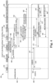
- FIG. 4 is an illustration of an event flow between a gateway device and a central monitoring station, generated in accordance with one or more embodiments of the present disclosure.
- communication flows 442 are shown for a configuration process 454 and an event alarm signal process 456.
- a technician 450 initiates the configuration process via the building owner/operator communication device 420 (mobile device with a specialized mobile software application constructed to provide the functionalities described herein).
- the building owner/operator communication device sends a request to the remote server 418 for receiver information to link the building owner/operator communication device to the response personnel status system at 460.
- the gateway device 410 sends authentication information to a transmitter 452 to make sure the user of the response personnel status system is authorized.
- the technician requests central station reporting information from the remote server to initiate an upload of report data to the central monitoring station server 408.
- the control panel 404 of the alarm system identifies an event 468 and initiates an event alarm signal 430 that is sent to the gateway device 410.
- the gateway device 410 then forwards the event alarm signal to a transmitter 452 that forwards the signal to the central monitoring station server 408.
- the central monitoring station server 408 then sends recording information 480/482 to the remote server for storage thereon for keeping a record of events and for estimating event timeframes as discussed herein.
- Each of these computing devices include a processor and memory which can function as described below. Also described below are other items that may be provided on such computing devices, such as user input and output components.
- the memory can be any type of storage medium that can be accessed by the processor to perform various examples of the present disclosure.
- the memory can be a non-transitory computer readable medium having computer readable instructions (e.g., executable instructions/computer program instructions) stored thereon that are executable by the processor in accordance with the present disclosure.
- the memory can be volatile or nonvolatile memory.
- the memory can also be removable (e.g., portable) memory, or non-removable (e.g., internal) memory.
- the memory can be random access memory (RAM) (e.g., dynamic random access memory (DRAM) and/or phase change random access memory (PCRAM)), read-only memory (ROM) (e.g., electrically erasable programmable read-only memory (EEPROM) and/or compact-disc read-only memory (CD-ROM)), flash memory, a laser disc, a digital versatile disc (DVD) or other optical storage, and/or a magnetic medium such as magnetic cassettes, tapes, or disks, among other types of memory.
- RAM random access memory
- DRAM dynamic random access memory
- PCRAM phase change random access memory
- ROM read-only memory
- EEPROM electrically erasable programmable read-only memory
- CD-ROM compact-disc read-only memory
- flash memory a laser disc, a digital versatile disc
- memory is illustrated as being located within the computing device, embodiments of the present disclosure are not so limited.
- memory can also be located internal to another computing resource (e.g., enabling computer readable instructions to be downloaded over the Internet or another wired or wireless connection).
- a computing device can also include a user interface.
- the user interface can display the embodiments illustrated in Figures 2 and 3 .
- a user e.g., operator of computing device can interact with the computing device via the user interface.
- the user interface can provide (e.g., display and/or present) information to the user of the computing device, and/or receive information from (e.g., input by) the user of computing device.
- user interface can be a graphical user interface (GUI) that can provide and/or receive information to and/or from the user of the computing device.
- GUI graphical user interface
- the display can be, for instance, a touch-screen (e.g., the GUI can include touch-screen capabilities).
- a display can include a television, computer monitor, mobile device screen, other type of display device, or any combination thereof, connected to mobile device and configured to receive a video signal output from the mobile device.
- user interface can include a keyboard and/or mouse the user can use to input information into the computing device.
- user interface can include a keyboard and/or mouse the user can use to input information into the computing device.
- Embodiments of the present disclosure are not limited to a particular type(s) of user interface.
- User interface can be localized to any language.
- user interface can utilize in any language, such as English, Spanish, German, French, Mandarin, Arabic, Japanese, Hindi, etc.
Landscapes
- Physics & Mathematics (AREA)
- General Physics & Mathematics (AREA)
- Business, Economics & Management (AREA)
- Emergency Management (AREA)
- Engineering & Computer Science (AREA)
- Computer Networks & Wireless Communication (AREA)
- Signal Processing (AREA)
- Alarm Systems (AREA)
- Selective Calling Equipment (AREA)
Applications Claiming Priority (2)
| Application Number | Priority Date | Filing Date | Title |
|---|---|---|---|
| US202163175348P | 2021-04-15 | 2021-04-15 | |
| EP22167858.4A EP4075402B1 (de) | 2021-04-15 | 2022-04-12 | Live-status-benachrichtigung von aktionen des einsatzpersonals an besitzer/betreiber eines gebäudes |
Related Parent Applications (1)
| Application Number | Title | Priority Date | Filing Date |
|---|---|---|---|
| EP22167858.4A Division EP4075402B1 (de) | 2021-04-15 | 2022-04-12 | Live-status-benachrichtigung von aktionen des einsatzpersonals an besitzer/betreiber eines gebäudes |
Publications (2)
| Publication Number | Publication Date |
|---|---|
| EP4498345A2 true EP4498345A2 (de) | 2025-01-29 |
| EP4498345A3 EP4498345A3 (de) | 2025-04-30 |
Family
ID=81307184
Family Applications (2)
| Application Number | Title | Priority Date | Filing Date |
|---|---|---|---|
| EP24219585.7A Pending EP4498345A3 (de) | 2021-04-15 | 2022-04-12 | Live-status-benachrichtigung von antwortpersonalaktionen an gebäudebesitzer/-betreiber |
| EP22167858.4A Active EP4075402B1 (de) | 2021-04-15 | 2022-04-12 | Live-status-benachrichtigung von aktionen des einsatzpersonals an besitzer/betreiber eines gebäudes |
Family Applications After (1)
| Application Number | Title | Priority Date | Filing Date |
|---|---|---|---|
| EP22167858.4A Active EP4075402B1 (de) | 2021-04-15 | 2022-04-12 | Live-status-benachrichtigung von aktionen des einsatzpersonals an besitzer/betreiber eines gebäudes |
Country Status (3)
| Country | Link |
|---|---|
| US (2) | US12394301B2 (de) |
| EP (2) | EP4498345A3 (de) |
| CN (1) | CN115223326B (de) |
Families Citing this family (2)
| Publication number | Priority date | Publication date | Assignee | Title |
|---|---|---|---|---|
| CN111402540B (zh) * | 2020-02-25 | 2021-08-24 | 王勇强 | 吸气式感烟火灾探测装置、方法及设备 |
| US12601653B2 (en) * | 2023-10-16 | 2026-04-14 | Saudi Arabian Oil Company | Assembly point system with active air quality and industrial gas emissions monitoring |
Family Cites Families (24)
| Publication number | Priority date | Publication date | Assignee | Title |
|---|---|---|---|---|
| US5061916A (en) | 1990-05-29 | 1991-10-29 | Barber-Colman Company | Event driven remote graphical reporting of building automation system parameters |
| US20070008099A1 (en) | 1999-09-01 | 2007-01-11 | Nettalon Security Systems, Inc. | Method and apparatus for remotely monitoring a site |
| JP4723813B2 (ja) | 2004-02-06 | 2011-07-13 | 富士通株式会社 | 携帯端末の緊急メール通知制御方法及びシステム |
| US20160065414A1 (en) | 2013-06-27 | 2016-03-03 | Ken Sundermeyer | Control system user interface |
| KR20050100491A (ko) | 2004-04-14 | 2005-10-19 | 주식회사 팬택앤큐리텔 | 온라인망을 기반으로 하는 위치 추적/보고 시스템 및 방법 |
| US7898410B2 (en) * | 2007-08-16 | 2011-03-01 | Advanced First Responder Solutions, Llc | Firefighter response system |
| JP5876371B2 (ja) | 2012-04-27 | 2016-03-02 | 京セラ株式会社 | 携帯電子機器、通信プログラム及び通信システム |
| CA3246645A1 (en) | 2012-11-12 | 2025-06-06 | Sielox, Llc | Emergency notification system and methods |
| KR20160032004A (ko) | 2013-04-23 | 2016-03-23 | 카나리 컨넥트 인코퍼레이티드 | 보안 및/또는 감시 장치 및 시스템 |
| US9426638B1 (en) * | 2013-05-14 | 2016-08-23 | Tapshield Protection, LLC | System and method for signaling and responding to an emergency situation |
| US20150317809A1 (en) * | 2014-05-05 | 2015-11-05 | The Curators Of The University Of Missouri | Systems and methods for emergency situation communications |
| WO2015187775A1 (en) | 2014-06-03 | 2015-12-10 | Otis Elevator Company | Integrated building evacuation system |
| US9953028B2 (en) * | 2015-01-09 | 2018-04-24 | International Business Machines Corporation | Cognitive contextualization of emergency management system communications |
| CN104851256A (zh) | 2015-04-07 | 2015-08-19 | 深圳市豪恩安全科技有限公司 | 一种安防出警系统 |
| US20160373910A1 (en) * | 2015-05-14 | 2016-12-22 | J. Darryl Moss | Emergency data gathering and communication system and methods of use |
| US10319210B2 (en) | 2016-05-31 | 2019-06-11 | Honeywell International Inc. | Translating building automation events into mobile notifications |
| KR20190040021A (ko) | 2016-08-17 | 2019-04-16 | 스코트 테크놀로지즈, 인크. | 사건 지휘 시스템에서의 제1 대응자에 대한 스마트 커미셔닝 |
| CN107274623A (zh) | 2017-08-01 | 2017-10-20 | 中消云(北京)物联网科技研究院有限公司 | 一种物联网消防家庭云检测系统 |
| US10872518B2 (en) | 2017-11-29 | 2020-12-22 | Alertpoint, LLC | Alerthub system with two touch badge |
| US10255780B1 (en) | 2018-05-29 | 2019-04-09 | David Wittenberg | System and method for detecting and mapping progression of a fire event |
| US11138855B2 (en) * | 2018-09-14 | 2021-10-05 | Avive Solutions, Inc. | Responder network |
| US20220122438A1 (en) * | 2018-10-12 | 2022-04-21 | David J. Miller | Active Shooter Shield System |
| US20200175843A1 (en) * | 2018-12-03 | 2020-06-04 | At& T Intellectual Property I, L.P. | Methods and systems for first responder access to localized presence and identification information |
| JP7288785B2 (ja) | 2019-03-29 | 2023-06-08 | ホーチキ株式会社 | 防災システム |
-
2022
- 2022-04-12 US US17/718,554 patent/US12394301B2/en active Active
- 2022-04-12 EP EP24219585.7A patent/EP4498345A3/de active Pending
- 2022-04-12 EP EP22167858.4A patent/EP4075402B1/de active Active
- 2022-04-15 CN CN202210397301.7A patent/CN115223326B/zh active Active
-
2025
- 2025-08-18 US US19/302,567 patent/US20250371968A1/en active Pending
Also Published As
| Publication number | Publication date |
|---|---|
| US20250371968A1 (en) | 2025-12-04 |
| US12394301B2 (en) | 2025-08-19 |
| CN115223326A (zh) | 2022-10-21 |
| EP4075402A1 (de) | 2022-10-19 |
| CN115223326B (zh) | 2025-04-08 |
| EP4498345A3 (de) | 2025-04-30 |
| EP4075402B1 (de) | 2024-12-25 |
| US20220335812A1 (en) | 2022-10-20 |
Similar Documents
| Publication | Publication Date | Title |
|---|---|---|
| US12254753B2 (en) | Determination and notification of a location of a building safety system event | |
| US20250371968A1 (en) | Live status notification of response personnel actions to building owner/operators | |
| US12293651B2 (en) | Self-testing fire sensing device for confirming a fire | |
| US9294708B2 (en) | System and method for interacting with digital video recorders through networking applications | |
| KR102042585B1 (ko) | 소방 방재 모니터링 시스템 및 방법 | |
| US20170193807A1 (en) | Alarm system on a device connected to a network | |
| US20230102182A1 (en) | Incident Management System | |
| CN117649739A (zh) | 基于目标楼宇的报警信息生成方法、装置、设备和介质 | |
| US11295601B2 (en) | System for supervising security devices | |
| US20240282189A1 (en) | Initiating a fire response at a self-testing fire sensing device | |
| US12131623B2 (en) | Systems, methods, and processes of providing first responders with live contextual information of building destinations for enhanced public safety operations | |
| US12400538B2 (en) | Systems, methods, and processes end to end digitization of alarm transmission for improved safety outcomes | |
| JPH09282583A (ja) | データ処理装置 | |
| CN121505814A (zh) | 消防安全管理方法、系统、设备及可读存储介质 | |
| HK1247480B (zh) | 用於预测事件是化学自杀的可能性的方法、系统和介质 |
Legal Events
| Date | Code | Title | Description |
|---|---|---|---|
| PUAI | Public reference made under article 153(3) epc to a published international application that has entered the european phase |
Free format text: ORIGINAL CODE: 0009012 |
|
| STAA | Information on the status of an ep patent application or granted ep patent |
Free format text: STATUS: THE APPLICATION HAS BEEN PUBLISHED |
|
| AC | Divisional application: reference to earlier application |
Ref document number: 4075402 Country of ref document: EP Kind code of ref document: P |
|
| AK | Designated contracting states |
Kind code of ref document: A2 Designated state(s): AL AT BE BG CH CY CZ DE DK EE ES FI FR GB GR HR HU IE IS IT LI LT LU LV MC MK MT NL NO PL PT RO RS SE SI SK SM TR |
|
| PUAL | Search report despatched |
Free format text: ORIGINAL CODE: 0009013 |
|
| AK | Designated contracting states |
Kind code of ref document: A3 Designated state(s): AL AT BE BG CH CY CZ DE DK EE ES FI FR GB GR HR HU IE IS IT LI LT LU LV MC MK MT NL NO PL PT RO RS SE SI SK SM TR |
|
| RIC1 | Information provided on ipc code assigned before grant |
Ipc: G08B 27/00 20060101AFI20250324BHEP |
|
| STAA | Information on the status of an ep patent application or granted ep patent |
Free format text: STATUS: REQUEST FOR EXAMINATION WAS MADE |
|
| 17P | Request for examination filed |
Effective date: 20251022 |
|
| STAA | Information on the status of an ep patent application or granted ep patent |
Free format text: STATUS: EXAMINATION IS IN PROGRESS |
|
| 17Q | First examination report despatched |
Effective date: 20260226 |