EP4498341A1 - Coin handling device and money depositing and withdrawal device - Google Patents
Coin handling device and money depositing and withdrawal device Download PDFInfo
- Publication number
- EP4498341A1 EP4498341A1 EP22933335.6A EP22933335A EP4498341A1 EP 4498341 A1 EP4498341 A1 EP 4498341A1 EP 22933335 A EP22933335 A EP 22933335A EP 4498341 A1 EP4498341 A1 EP 4498341A1
- Authority
- EP
- European Patent Office
- Prior art keywords
- coin
- unit
- receiving unit
- hole
- rotating plate
- Prior art date
- Legal status (The legal status is an assumption and is not a legal conclusion. Google has not performed a legal analysis and makes no representation as to the accuracy of the status listed.)
- Withdrawn
Links
Images





Classifications
-
- G—PHYSICS
- G07—CHECKING-DEVICES
- G07D—HANDLING OF COINS OR VALUABLE PAPERS, e.g. TESTING, SORTING BY DENOMINATIONS, COUNTING, DISPENSING, CHANGING OR DEPOSITING
- G07D1/00—Coin dispensers
- G07D1/02—Coin dispensers giving change
- G07D1/06—Coin dispensers giving change dispensing the difference between a sum paid and a sum charged
-
- G—PHYSICS
- G07—CHECKING-DEVICES
- G07D—HANDLING OF COINS OR VALUABLE PAPERS, e.g. TESTING, SORTING BY DENOMINATIONS, COUNTING, DISPENSING, CHANGING OR DEPOSITING
- G07D9/00—Counting coins; Handling of coins not provided for in the other groups of this subclass
- G07D9/008—Feeding coins from bulk
-
- G—PHYSICS
- G07—CHECKING-DEVICES
- G07D—HANDLING OF COINS OR VALUABLE PAPERS, e.g. TESTING, SORTING BY DENOMINATIONS, COUNTING, DISPENSING, CHANGING OR DEPOSITING
- G07D1/00—Coin dispensers
-
- G—PHYSICS
- G07—CHECKING-DEVICES
- G07D—HANDLING OF COINS OR VALUABLE PAPERS, e.g. TESTING, SORTING BY DENOMINATIONS, COUNTING, DISPENSING, CHANGING OR DEPOSITING
- G07D3/00—Sorting a mixed bulk of coins into denominations
- G07D3/02—Sorting coins by means of graded apertures
- G07D3/06—Sorting coins by means of graded apertures arranged along a circular path
-
- G—PHYSICS
- G07—CHECKING-DEVICES
- G07D—HANDLING OF COINS OR VALUABLE PAPERS, e.g. TESTING, SORTING BY DENOMINATIONS, COUNTING, DISPENSING, CHANGING OR DEPOSITING
- G07D3/00—Sorting a mixed bulk of coins into denominations
- G07D3/14—Apparatus driven under control of coin-sensing elements
-
- G—PHYSICS
- G07—CHECKING-DEVICES
- G07D—HANDLING OF COINS OR VALUABLE PAPERS, e.g. TESTING, SORTING BY DENOMINATIONS, COUNTING, DISPENSING, CHANGING OR DEPOSITING
- G07D2201/00—Coin dispensers
Definitions
- the present invention relates to a coin handling apparatus and a money depositing/dispensing apparatus including the coin handling apparatus.
- a money depositing/dispensing apparatus for depositing money for a product when a customer purchases the product at a store such as a supermarket or when a store clerk performs a checkout process for the product.
- a money depositing/dispensing apparatus includes a coin depositing/dispensing unit (coin depositing/dispensing apparatus) and a bill depositing/dispensing unit (bill depositing/dispensing apparatus).
- Patent Literature 1 and 2 an apparatus capable of collectively inserting a plurality of coins has also been proposed (see, for example, Patent Literature 1 and 2).
- a larger foreign object than a coin of a maximum size which is supposed to be inserted (the foreign object is, for example, a coin of a different country which is not supposed to be inserted) is not supplied to the receiving passage and continues to stay at the coin receiving unit in a case where the foreign object is inserted.
- the large foreign object hinders the conveyance of the coins.
- An object of the present invention is to provide a coin handling apparatus and a money depositing/dispensing apparatus capable of discharging a larger foreign object than a coin with a simple configuration.
- a coin handling apparatus includes a coin receiving unit having a coin receiving port capable of collectively receiving a plurality of coins, a rotating plate disposed in the coin receiving unit and rotating to scoop up a coin in the coin receiving unit, a sorting member provided with a coin hole having a size that makes it possible for a coin of a maximum size scooped up by the rotating plate to pass therethrough, and a large foreign object hole located on a downstream side of the coin hole in a rotation direction of the rotating plate and larger than the coin of the maximum size, a receiving passage connected to the coin hole of the sorting member, and a discharge passage connected to the large foreign object hole of the sorting member.
- a money depositing/dispensing apparatus in another aspect, includes the coin handling apparatus and a bill depositing/dispensing unit.
- the coin handling apparatus is a coin depositing/dispensing unit.
- a larger foreign object than a coin can be discharged with a simple configuration.
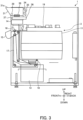
- Figs. 1 to 3 are a perspective schematic view, a front schematic view, and a right schematic view illustrating an internal structure of a money depositing/dispensing apparatus 1 according to an embodiment.
- Figs. 1 to 3 and Figs. 4 to 8B to be described below are illustrative only for a case where a customer (user) side of the money depositing/dispensing apparatus 1 is the front direction, and for example, the up-down direction is a vertical direction, and the front-back direction and the right-left direction are horizontal directions.
- the money depositing/dispensing apparatus 1 includes a bill recycling unit 2, a coin unit 3, and a controller unit 4.
- the money depositing/dispensing apparatus 1 is used, for example, in a store such as a supermarket in order for a customer or a store clerk to deposit or dispense money for a product, or in order for a store clerk to deposit or dispense money in a backyard of the store.
- the money depositing/dispensing apparatus 1 can be arranged at any place, as well as at a store.
- the bill recycling unit 2 is a bill depositing/dispensing unit (bill depositing/dispensing apparatus) for depositing or dispensing bills.
- the coin unit 3 is an example of a coin handling apparatus that handles coins, and is a coin depositing/dispensing unit (coin depositing/dispensing apparatus) for depositing or dispensing coins.
- the coin handling apparatus is only required to at least receive coins and is not limited to the apparatus (coin unit 3) used in the money depositing/dispensing apparatus 1. Note that the coin unit 3 (coin depositing/dispensing apparatus) may be used alone as a money depositing/dispensing apparatus without the bill recycling unit 2 (bill depositing/dispensing unit).
- the coin unit 3 includes a coin receiving unit 31, a coin recycling unit 11, a coin overflow cassette 12, a coin recovery cassette 13, a coin acceptor 14, a coin dispensing unit 15, a coin sorter unit 16, a coin lifter unit 17, a coin recovery stopper unit 18, and a control unit 19.
- the coin unit 3 further includes a rotating plate 32, a sorting plate 33, a receiving passage 34, a discharge passage 35, a slide rail 36, a slider 37, a hinge 38, and a coin detecting sensor 39, which will be described below.
- the controller unit 4 is a unit for providing a command to the money depositing/dispensing apparatus 1 and displaying information such as a state of the money depositing/dispensing apparatus 1 and a purchase amount for a product.
- the controller unit 4 will also be described below.
- the coin receiving unit 31 has a coin receiving port 31a capable of collectively receiving a plurality of coins for a product billing amount or the like.
- the coin recycling unit 11 is a unit that stores coins inserted through the coin receiving unit 31 and received from the coin acceptor (depositing port) 14 and stores coins that can be dispensed through the coin dispensing unit (dispensing port) 15.
- the coin overflow cassette 12 is a unit that stores coins that cannot be dispensed through the coin dispensing unit 15.
- the coin stored in the coin overflow cassette 12 is a coin that has moved to avoid a full state of the coin recycling unit 11, and can thus be said to be, for example, a coin that can be reused in a store.
- the coin recovery cassette 13 is a cassette that stores the recovered coins in the coin unit 3, particularly, in the coin recycling unit 11.
- the coins stored in the coin recovery cassette 13 are, for example, coins to be deposited in a bank as a sales amount.
- the coin acceptor 14 has a discrimination function of discriminating coins inserted through the coin receiving unit 31.
- the discrimination function is a function of discriminating among a genuine coin, a counterfeit coin, a token coin, and the like.
- the discrimination function also includes a function of identifying the coin type.
- the coin dispensing unit 15 is an example of a coin discharging unit that discharges coins from the coin unit 3 (coin handling apparatus), and dispenses coins such as change.
- the coin sorter unit 16 sorts the coins supplied from the coin acceptor 14 and supplies the coins to the coin recycling unit 11, the coin overflow cassette 12, or the coin dispensing unit 15. Further, in a case where the coin is a genuine coin on the basis of the discrimination result using the discrimination function of the coin acceptor 14, the coin sorter unit 16 supplies the genuine coin to the coin recycling unit 11 or the coin overflow cassette 12. In a case where the coin is a counterfeit coin, the coin sorter unit 16 supplies the counterfeit coin to the coin dispensing unit 15.
- the coin recovery stopper unit 18 is a stopper for opening and closing a coin discharge port for discharging coins for each coin type hopper in the coin recycling unit 11.
- the coin lifter unit 17 is a lift (conveying unit) that conveys the coins discharged from the coin discharge port to the coin acceptor 14 according to an opening operation of the coin recovery stopper unit 18 and a forward rotation operation of the coin lifter unit 17.
- the coin lifter unit 17 is a lift (conveying unit) that conveys the coins discharged from the coin discharge port to the coin recovery cassette 13 according to the opening operation of the coin recovery stopper unit 18 and a reverse rotation operation of the coin lifter unit 17.
- the control unit 19 includes, for example, a processor and a memory.
- the processor is, for example, a central processing unit (CPU) that functions as an arithmetic processing device that controls the operation of each unit of the coin unit 3.
- the memory is a read only memory (ROM) that is a read-only semiconductor memory in which a predetermined control program is recorded in advance, a random access memory (RAM) that is a semiconductor memory that is used as a working storage area as necessary when the processor executes various control programs and is writable and readable at any time, or the like.
- Fig. 4 is a front view illustrating an internal structure of the coin receiving unit 31.
- Fig. 5 is a view of the rotating plate 32 and the sorting plate 33 as viewed in the V direction in Fig. 4 .
- Fig. 6 is a view of the sorting plate 33 as viewed in the V direction in Fig. 4 with the rotating plate 32 removed.
- the inner bottom surface, indicated by the broken line, of the coin receiving unit 31 is inclined toward the bottom portion of the rotating plate 32 from the right portion to the central portion so as to guide the received coins to the rotating plate 32.
- the inner bottom surface of the coin receiving unit 31 is inclined toward the bottom portion of the rotating plate 32 from the front portion to the back portion.
- the rotating plate 32 is disposed in the coin receiving unit 31 at an inclination angle ⁇ (for example, 10 degrees counterclockwise in Fig. 4 ) with respect to a virtual vertical plane V.
- the rotating plate 32 rotates to scoop up the coins in the coin receiving unit 31 (for example, clockwise in Fig. 5 ).
- the rotating plate 32 is provided with, for example, eight holding holes 32a (illustrated in Fig. 6 by the two-dot chain line which is an imaginary line since the rotating plate 32 is omitted in Fig. 6 ) having the same size (diameter d2) as a large foreign object hole 33b of the sorting plate 33 to be described below at equal intervals in the rotation direction.
- the holding hole 32a holds a coin or a foreign object between the rotating plate 32 and the sorting plate 33 disposed to overlap with the left portion of the rotating plate 32 at the same inclination angle ⁇ as that of the rotating plate 32.
- the sorting plate 33 is provided with a coin hole 33a having a size (diameter d1) that makes it possible for a coin of the maximum size scooped up by the rotating plate 32 to pass therethrough, the large foreign object hole 33b (diameter d2 (d2 > d1)) located on the downstream side of the coin hole 33a in the rotation direction of the rotating plate 32 and larger than the coin of the maximum size, and a small foreign object hole 33c located on the upstream side of the coin hole 33a in the rotation direction of the rotating plate 32 and having a size (diameter d3 (d3 ⁇ d1)) that makes it impossible for a coin of the minimum size scooped up by the rotating plate 32 to pass therethrough.
- a coin hole 33a having a size (diameter d1) that makes it possible for a coin of the maximum size scooped up by the rotating plate 32 to pass therethrough
- the large foreign object hole 33b located on the downstream side of the coin hole 33a in the rotation direction of the
- the upstream side and the downstream side in the rotation direction of the rotating plate 32 are those in a case where, when the rotating plate 32 makes one rotation with the bottom portion of the rotating plate 32 as a starting point, the early stage of the rotation is defined as an upstream end, and the last stage of the rotation is defined as a downstream end.
- the large foreign object hole 33b of the sorting plate 33 and the holding hole 32a of the rotating plate 32 are provided in the same size (diameter d2), but both are only required to be larger than the coin hole 33a (diameter d1).
- the sorting plate 33 is an example of a sorting member provided with at least the coin hole 33a and the large foreign object hole 33b, and its shape is not limited to a plate shape.
- the small foreign object hole 33c of the sorting plate 33 may be omitted.
- a smaller foreign object than the coin of the minimum size is sent to the coin acceptor 14 together with coins, and is distinguished from the coins.
- the receiving passage 34 illustrated by the broken line which is a hidden line in Fig. 4 and illustrated by the two-dot chain line which is an imaginary line in Fig. 5 is connected to the left end of the coin hole 33a of the sorting plate 33 and penetrates the left wall portion of the coin receiving unit 31 as illustrated in Fig. 1 , for example.
- the receiving passage 34 sends the coin having passed through the coin hole 33a to the coin acceptor 14.
- the receiving passage 34 is preferably made of a flexible material so as to allow the coin receiving unit 31 to perform the drawing operation or the inclination operation.
- the discharge passage 35 illustrated by the broken line which is a hidden line in Fig. 4 and illustrated by the two-dot chain line which is an imaginary line in Fig. 5 is connected to the large foreign object hole 33b and the small foreign object hole 33c of the sorting plate 33, and penetrates the rear wall portion of the coin receiving unit 31, for example, although not illustrated.
- the discharge passage 35 sends the foreign object having passed through the large foreign object hole 33b and larger than the coin of the maximum size and the foreign object having passed through the small foreign object hole 33c and smaller than the coin of the minimum size to the coin dispensing unit 15. Note that, in the example indicated by the two-dot chain line in Fig.
- the discharge passage 35 is bifurcated and connected to the large foreign object hole 33b and the small foreign object hole 33c, but two discharge passages may be provided independently one of which is connected to the large foreign object hole 33b and the other of which is connected to the small foreign object hole 33c.
- the discharge passage 35 is preferably made of a flexible material so as to allow the coin receiving unit 31 to perform the drawing operation or the inclination operation, in a similar manner to the case of the receiving passage 34.
- Figs. 7A and 7B are right side views for explaining the drawing operation of the coin receiving unit 31.
- the slide rail 36 is disposed to draw out the coin receiving unit 31 forward (toward the customer).
- the slide rail 36 slidably holds the slider 37 connected to the lower portion of the coin receiving unit 31 in the front-back direction, thereby making the coin receiving unit 31 slidable in the front-back direction.
- a person in charge or the like draws out the coin receiving unit 31 (slider 37) forward, for example, until the entire coin receiving unit 31 protrudes from the front surface of the money depositing/dispensing apparatus 1, whereby it is possible to easily remove the coin or the foreign object clogged inside the coin receiving unit 31.
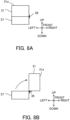
- Figs. 8A and 8B are front views for explaining the inclination operation of the coin receiving unit 31.
- the hinge 38 is disposed at the right end boundary portion between the coin receiving unit 31 and the slide rail 36.
- the hinge 38 is an example of a support member that supports the coin receiving unit 31 in an inclinable manner.
- the hinge 38 supports the coin receiving unit 31 so that the coin receiving unit 31 is rotatable clockwise by 90 degrees until the coin receiving port 31a faces to the right.
- the inclination operation of the coin receiving unit 31 is preferably performed in a state where the coin receiving unit 31 is drawn forward as described above.
- the inclination direction of the coin receiving unit 31 is not limited to the right direction, and may be the left direction, the front direction, or the like.
- the inclinable angle of the coin receiving unit 31 by the support of the hinge 38 (support member) is not limited to 90 degrees, and may be any angle.
- the coin detecting sensor 39 indicated by the broken line (hidden line) in Figs. 7A and 7B detects a coin in the coin receiving unit 31 on the basis of the detection light emitted in the coin receiving unit 31 being shielded by the coin.
- the above-described rotating plate 32 preferably rotates on the basis of detection of a coin by the coin detecting sensor 39.
- the rotation operation of the rotating plate 32 is preferably performed, for example, by the above-described control unit 19 driving and controlling a rotation drive unit which is an actuator such as a not-illustrated motor.
- the coin detecting sensor 39 may be omitted, and the rotating plate 32 may always rotate, for example, when the power of the money depositing/dispensing apparatus 1 is turned on, when coins are received in the coin receiving unit 31 (when insertion of coins is requested), or the like.
- Fig. 9 is a block diagram illustrating an example of a functional configuration of the controller unit 4 illustrated in Fig. 1 .
- the controller unit 4 illustrated in Fig. 9 includes a display unit 41, a keyboard/mouse 42, a scanner 43, a printer 44, a communication unit 45, and a control unit 46.
- the display unit 41 is, for example, an output interface that displays various types of information such as a product billing amount.
- the keyboard/mouse 42 is, for example, an input interface for inputting various types of information such as a command.
- the scanner 43 is, for example, an input interface that reads a barcode or the like attached to a product.
- the printer 44 is, for example, an output interface that prints out various types of information such as a purchase receipt for a product or the like.
- the communication unit 45 is a communication interface that connects the bill recycling unit 2 to the coin unit 3 by means of wireless communication.
- the control unit 46 controls the entire controller unit 4.
- the control unit 46 of the controller unit 4 preferably includes a processor, a memory, and the like similarly to the case of the control unit 19 of the coin unit 3.
- the coin unit 3 which is an example of a coin handling apparatus includes the coin receiving unit 31 having the coin receiving port 31a capable of collectively receiving a plurality of coins, the rotating plate 32 disposed in the coin receiving unit 31 and rotating to scoop up a coin in the coin receiving unit 31, the sorting plate 33 provided with the coin hole 33a having a size (diameter d1) that makes it possible for a coin of a maximum size scooped up by the rotating plate 32 to pass therethrough, and the large foreign object hole 33b (diameter d2) located on a downstream side of the coin hole 33a in a rotation direction of the rotating plate 32 and larger than the coin of the maximum size and serving as an example of a sorting member, the receiving passage 34 connected to the coin hole 33a of the sorting plate 33, and the discharge passage 35 connected to the large foreign object hole 33b of the sorting plate 33.
- the coin receiving unit 31 having the coin receiving port 31a capable of collectively receiving a plurality of coins
- the rotating plate 32 disposed in the coin receiving unit 31 and
- the money depositing/dispensing apparatus 1 includes the coin handling apparatus and the bill recycling unit 2 serving as an example of a bill depositing/dispensing unit.
- the coin handling apparatus is a coin depositing/dispensing unit (for example, the coin unit 3).
- the coin unit 3 and the money depositing/dispensing apparatus 1 described above since the coin receiving port 31a of the coin receiving unit 31 can collectively receive a plurality of coins, the convenience of the customer can be enhanced.
- the large foreign object hole 33b (diameter d2) larger than the coin of the maximum size is provided in the sorting plate 33, it is possible to prevent a larger foreign object than the coin of the maximum size (the foreign object is, for example, a coin of a different country which is not supposed to be inserted) from staying at the coin receiving unit 31 or hindering the conveyance of coins without the need for a mechanism operated by a different driving force from that for the rotating plate 32. Therefore, according to the present embodiment, a larger foreign object than a coin can be discharged with a simple configuration.
- the sorting plate 33 is further provided with the small foreign object hole 33c located on an upstream side of the coin hole 33a in the rotation direction of the rotating plate 32 and having a size that makes it impossible for a coin of a minimum size scooped up by the rotating plate 32 to pass therethrough.
- the discharge passage 35 is connected to the large foreign object hole 33b and the small foreign object hole 33c.
- the coin unit 3 further includes the slide rail 36 for drawing out the coin receiving unit 31.
- the coin unit 3 further includes the hinge 38 serving as an example of a support member supporting the coin receiving unit 31 in an inclinable manner.
- the coin unit 3 further includes the coin detecting sensor 39 detecting a coin in the coin receiving unit 31.
- the rotating plate 32 rotates on a basis of detection of a coin by the coin detecting sensor 39.
- the rotating plate 32 can be rotated only when a coin is inserted into the coin receiving unit 31, a foreign object can be discharged with low power consumption.
- the present invention is not limited to the above-described embodiment as it is, and can be embodied by modifying the components thereof.
- various inventions can be formed by appropriately combining the plurality of components disclosed in the present embodiment. In this manner, various modifications and applications of the invention can be made without departing from the spirit of the invention.
Landscapes
- Physics & Mathematics (AREA)
- General Physics & Mathematics (AREA)
- Control Of Vending Devices And Auxiliary Devices For Vending Devices (AREA)
- Testing Of Coins (AREA)
Abstract
Description
- The present invention relates to a coin handling apparatus and a money depositing/dispensing apparatus including the coin handling apparatus.
- There is a money depositing/dispensing apparatus for depositing money for a product when a customer purchases the product at a store such as a supermarket or when a store clerk performs a checkout process for the product. Such a money depositing/dispensing apparatus includes a coin depositing/dispensing unit (coin depositing/dispensing apparatus) and a bill depositing/dispensing unit (bill depositing/dispensing apparatus).
- In addition, there is a case where a coin receiving apparatus (coin depositing apparatus) that only receives coins is used. Usually, in the coin handling apparatus such as the aforementioned coin depositing/dispensing apparatus and coin receiving apparatus, coins are inserted one by one.
- On the other hand, an apparatus capable of collectively inserting a plurality of coins has also been proposed (see, for example,
Patent Literature 1 and 2). -
- Patent Literature 1:
JP 8-180240 A - Patent Literature 2:
JP 2003-144615 A - Meanwhile, in an apparatus in which, in a coin receiving unit having a coin receiving port through which coins can be collectively inserted, coins are scooped up by rotation of a rotating plate and supplied to a receiving passage, a larger foreign object than a coin of a maximum size which is supposed to be inserted (the foreign object is, for example, a coin of a different country which is not supposed to be inserted) is not supplied to the receiving passage and continues to stay at the coin receiving unit in a case where the foreign object is inserted. In addition, the large foreign object hinders the conveyance of the coins.
- Under such circumstances, it is conceivable to arrange a mechanism for eliminating the large foreign object, but in a case where such a mechanism operated by a different driving force from that for the rotating plate is provided, the structure of the coin handling apparatus becomes complicated.
- An object of the present invention is to provide a coin handling apparatus and a money depositing/dispensing apparatus capable of discharging a larger foreign object than a coin with a simple configuration.
- In one aspect, a coin handling apparatus includes a coin receiving unit having a coin receiving port capable of collectively receiving a plurality of coins, a rotating plate disposed in the coin receiving unit and rotating to scoop up a coin in the coin receiving unit, a sorting member provided with a coin hole having a size that makes it possible for a coin of a maximum size scooped up by the rotating plate to pass therethrough, and a large foreign object hole located on a downstream side of the coin hole in a rotation direction of the rotating plate and larger than the coin of the maximum size, a receiving passage connected to the coin hole of the sorting member, and a discharge passage connected to the large foreign object hole of the sorting member.
- In another aspect, a money depositing/dispensing apparatus includes the coin handling apparatus and a bill depositing/dispensing unit. The coin handling apparatus is a coin depositing/dispensing unit.
- According to the aforementioned aspect, a larger foreign object than a coin can be discharged with a simple configuration.
-
-
Fig. 1 is a perspective schematic view illustrating an internal structure of a money depositing/dispensing apparatus according to an embodiment. -
Fig. 2 is a front schematic view illustrating the internal structure of the money depositing/dispensing apparatus according to the embodiment. -
Fig. 3 is a right schematic view illustrating the internal structure of the money depositing/dispensing apparatus according to the embodiment. -
Fig. 4 is a front view illustrating an internal structure of a coin receiving unit according to the embodiment. -
Fig. 5 is a view of a rotating plate and a sorting plate according to the embodiment as viewed in the V direction inFig. 4 . -
Fig. 6 is a view of the sorting plate as viewed in the V direction inFig. 4 with the rotating plate removed. -
Fig. 7A is a right side view (part 1) illustrating a drawing operation of the coin receiving unit according to the embodiment. -
Fig. 7B is a right side view (part 2) illustrating the drawing operation of the coin receiving unit according to the embodiment. -
Fig. 8A is a front view (part 1) illustrating an inclination operation of the coin receiving unit according to the embodiment. -
Fig. 8B is a front view (part 2) illustrating the inclination operation of the coin receiving unit according to the embodiment. -
Fig. 9 is a block diagram illustrating an example of a functional configuration of a controller unit according to the embodiment. - Hereinbelow, a coin handling apparatus and a money depositing/dispensing apparatus according to an embodiment of the present invention will be described with reference to the drawings.
-
Figs. 1 to 3 are a perspective schematic view, a front schematic view, and a right schematic view illustrating an internal structure of a money depositing/dispensingapparatus 1 according to an embodiment. - Note that the up-down, front-back, and right-left directions illustrated in
Figs. 1 to 3 andFigs. 4 to 8B to be described below are illustrative only for a case where a customer (user) side of the money depositing/dispensingapparatus 1 is the front direction, and for example, the up-down direction is a vertical direction, and the front-back direction and the right-left direction are horizontal directions. - As illustrated in
Fig. 1 , the money depositing/dispensingapparatus 1 includes abill recycling unit 2, acoin unit 3, and acontroller unit 4. The money depositing/dispensingapparatus 1 is used, for example, in a store such as a supermarket in order for a customer or a store clerk to deposit or dispense money for a product, or in order for a store clerk to deposit or dispense money in a backyard of the store. The money depositing/dispensingapparatus 1 can be arranged at any place, as well as at a store. - The
bill recycling unit 2 is a bill depositing/dispensing unit (bill depositing/dispensing apparatus) for depositing or dispensing bills. - The
coin unit 3 is an example of a coin handling apparatus that handles coins, and is a coin depositing/dispensing unit (coin depositing/dispensing apparatus) for depositing or dispensing coins. The coin handling apparatus is only required to at least receive coins and is not limited to the apparatus (coin unit 3) used in the money depositing/dispensingapparatus 1. Note that the coin unit 3 (coin depositing/dispensing apparatus) may be used alone as a money depositing/dispensing apparatus without the bill recycling unit 2 (bill depositing/dispensing unit). - As illustrated in
Figs. 1 to 3 , thecoin unit 3 includes acoin receiving unit 31, acoin recycling unit 11, acoin overflow cassette 12, acoin recovery cassette 13, acoin acceptor 14, acoin dispensing unit 15, acoin sorter unit 16, acoin lifter unit 17, a coinrecovery stopper unit 18, and acontrol unit 19. Thecoin unit 3 further includes arotating plate 32, asorting plate 33, areceiving passage 34, adischarge passage 35, aslide rail 36, aslider 37, ahinge 38, and acoin detecting sensor 39, which will be described below. - The
controller unit 4 is a unit for providing a command to the money depositing/dispensingapparatus 1 and displaying information such as a state of the money depositing/dispensingapparatus 1 and a purchase amount for a product. Thecontroller unit 4 will also be described below. - The
coin receiving unit 31 has acoin receiving port 31a capable of collectively receiving a plurality of coins for a product billing amount or the like. - The
coin recycling unit 11 is a unit that stores coins inserted through thecoin receiving unit 31 and received from the coin acceptor (depositing port) 14 and stores coins that can be dispensed through the coin dispensing unit (dispensing port) 15. - The
coin overflow cassette 12 is a unit that stores coins that cannot be dispensed through thecoin dispensing unit 15. The coin stored in thecoin overflow cassette 12 is a coin that has moved to avoid a full state of thecoin recycling unit 11, and can thus be said to be, for example, a coin that can be reused in a store. - The
coin recovery cassette 13 is a cassette that stores the recovered coins in thecoin unit 3, particularly, in thecoin recycling unit 11. The coins stored in thecoin recovery cassette 13 are, for example, coins to be deposited in a bank as a sales amount. - The
coin acceptor 14 has a discrimination function of discriminating coins inserted through thecoin receiving unit 31. The discrimination function is a function of discriminating among a genuine coin, a counterfeit coin, a token coin, and the like. The discrimination function also includes a function of identifying the coin type. - The
coin dispensing unit 15 is an example of a coin discharging unit that discharges coins from the coin unit 3 (coin handling apparatus), and dispenses coins such as change. - The
coin sorter unit 16 sorts the coins supplied from thecoin acceptor 14 and supplies the coins to thecoin recycling unit 11, thecoin overflow cassette 12, or thecoin dispensing unit 15. Further, in a case where the coin is a genuine coin on the basis of the discrimination result using the discrimination function of thecoin acceptor 14, thecoin sorter unit 16 supplies the genuine coin to thecoin recycling unit 11 or thecoin overflow cassette 12. In a case where the coin is a counterfeit coin, thecoin sorter unit 16 supplies the counterfeit coin to thecoin dispensing unit 15. - The coin
recovery stopper unit 18 is a stopper for opening and closing a coin discharge port for discharging coins for each coin type hopper in thecoin recycling unit 11. - The
coin lifter unit 17 is a lift (conveying unit) that conveys the coins discharged from the coin discharge port to thecoin acceptor 14 according to an opening operation of the coinrecovery stopper unit 18 and a forward rotation operation of thecoin lifter unit 17. In addition, thecoin lifter unit 17 is a lift (conveying unit) that conveys the coins discharged from the coin discharge port to thecoin recovery cassette 13 according to the opening operation of the coinrecovery stopper unit 18 and a reverse rotation operation of thecoin lifter unit 17. - The
control unit 19 includes, for example, a processor and a memory. The processor is, for example, a central processing unit (CPU) that functions as an arithmetic processing device that controls the operation of each unit of thecoin unit 3. The memory is a read only memory (ROM) that is a read-only semiconductor memory in which a predetermined control program is recorded in advance, a random access memory (RAM) that is a semiconductor memory that is used as a working storage area as necessary when the processor executes various control programs and is writable and readable at any time, or the like. -
Fig. 4 is a front view illustrating an internal structure of thecoin receiving unit 31. -
Fig. 5 is a view of therotating plate 32 and the sortingplate 33 as viewed in the V direction inFig. 4 . -
Fig. 6 is a view of the sortingplate 33 as viewed in the V direction inFig. 4 with therotating plate 32 removed. - As illustrated in
Fig. 4 , the inner bottom surface, indicated by the broken line, of thecoin receiving unit 31 is inclined toward the bottom portion of therotating plate 32 from the right portion to the central portion so as to guide the received coins to therotating plate 32. In addition, as partially illustrated inFig. 1 , the inner bottom surface of thecoin receiving unit 31 is inclined toward the bottom portion of therotating plate 32 from the front portion to the back portion. - The rotating
plate 32 is disposed in thecoin receiving unit 31 at an inclination angle θ (for example, 10 degrees counterclockwise inFig. 4 ) with respect to a virtual vertical plane V. The rotatingplate 32 rotates to scoop up the coins in the coin receiving unit 31 (for example, clockwise inFig. 5 ). As illustrated inFig. 5 , the rotatingplate 32 is provided with, for example, eight holdingholes 32a (illustrated inFig. 6 by the two-dot chain line which is an imaginary line since therotating plate 32 is omitted inFig. 6 ) having the same size (diameter d2) as a largeforeign object hole 33b of the sortingplate 33 to be described below at equal intervals in the rotation direction. The holdinghole 32a holds a coin or a foreign object between therotating plate 32 and the sortingplate 33 disposed to overlap with the left portion of therotating plate 32 at the same inclination angle θ as that of therotating plate 32. - As illustrated in
Fig. 6 , the sortingplate 33 is provided with acoin hole 33a having a size (diameter d1) that makes it possible for a coin of the maximum size scooped up by the rotatingplate 32 to pass therethrough, the largeforeign object hole 33b (diameter d2 (d2 > d1)) located on the downstream side of thecoin hole 33a in the rotation direction of therotating plate 32 and larger than the coin of the maximum size, and a smallforeign object hole 33c located on the upstream side of thecoin hole 33a in the rotation direction of therotating plate 32 and having a size (diameter d3 (d3 < d1)) that makes it impossible for a coin of the minimum size scooped up by the rotatingplate 32 to pass therethrough. Note that the upstream side and the downstream side in the rotation direction of therotating plate 32 are those in a case where, when therotating plate 32 makes one rotation with the bottom portion of therotating plate 32 as a starting point, the early stage of the rotation is defined as an upstream end, and the last stage of the rotation is defined as a downstream end. In addition, the largeforeign object hole 33b of the sortingplate 33 and the holdinghole 32a of therotating plate 32 are provided in the same size (diameter d2), but both are only required to be larger than thecoin hole 33a (diameter d1). The sortingplate 33 is an example of a sorting member provided with at least thecoin hole 33a and the largeforeign object hole 33b, and its shape is not limited to a plate shape. Further, the smallforeign object hole 33c of the sortingplate 33 may be omitted. In a case where the smallforeign object hole 33c is omitted, a smaller foreign object than the coin of the minimum size is sent to thecoin acceptor 14 together with coins, and is distinguished from the coins. - The receiving
passage 34 illustrated by the broken line which is a hidden line inFig. 4 and illustrated by the two-dot chain line which is an imaginary line inFig. 5 is connected to the left end of thecoin hole 33a of the sortingplate 33 and penetrates the left wall portion of thecoin receiving unit 31 as illustrated inFig. 1 , for example. The receivingpassage 34 sends the coin having passed through thecoin hole 33a to thecoin acceptor 14. Note that, in a case where thecoin receiving unit 31 can be drawn out or can be inclined as described below, the receivingpassage 34 is preferably made of a flexible material so as to allow thecoin receiving unit 31 to perform the drawing operation or the inclination operation. - The
discharge passage 35 illustrated by the broken line which is a hidden line inFig. 4 and illustrated by the two-dot chain line which is an imaginary line inFig. 5 is connected to the largeforeign object hole 33b and the smallforeign object hole 33c of the sortingplate 33, and penetrates the rear wall portion of thecoin receiving unit 31, for example, although not illustrated. Thedischarge passage 35 sends the foreign object having passed through the largeforeign object hole 33b and larger than the coin of the maximum size and the foreign object having passed through the smallforeign object hole 33c and smaller than the coin of the minimum size to thecoin dispensing unit 15. Note that, in the example indicated by the two-dot chain line inFig. 5 , thedischarge passage 35 is bifurcated and connected to the largeforeign object hole 33b and the smallforeign object hole 33c, but two discharge passages may be provided independently one of which is connected to the largeforeign object hole 33b and the other of which is connected to the smallforeign object hole 33c. In addition, in a case where thecoin receiving unit 31 can be drawn out or can be inclined, thedischarge passage 35 is preferably made of a flexible material so as to allow thecoin receiving unit 31 to perform the drawing operation or the inclination operation, in a similar manner to the case of the receivingpassage 34. -
Figs. 7A and 7B are right side views for explaining the drawing operation of thecoin receiving unit 31. - As illustrated in
Figs. 7A and 7B , theslide rail 36 is disposed to draw out thecoin receiving unit 31 forward (toward the customer). Theslide rail 36 slidably holds theslider 37 connected to the lower portion of thecoin receiving unit 31 in the front-back direction, thereby making thecoin receiving unit 31 slidable in the front-back direction. - As illustrated in
Fig. 7B , a person in charge or the like draws out the coin receiving unit 31 (slider 37) forward, for example, until the entirecoin receiving unit 31 protrudes from the front surface of the money depositing/dispensing apparatus 1, whereby it is possible to easily remove the coin or the foreign object clogged inside thecoin receiving unit 31. -
Figs. 8A and 8B are front views for explaining the inclination operation of thecoin receiving unit 31. - As illustrated in
Figs. 7A, 7B ,8A, and 8B , thehinge 38 is disposed at the right end boundary portion between thecoin receiving unit 31 and theslide rail 36. Thehinge 38 is an example of a support member that supports thecoin receiving unit 31 in an inclinable manner. - As illustrated in
Fig. 8B , for example, thehinge 38 supports thecoin receiving unit 31 so that thecoin receiving unit 31 is rotatable clockwise by 90 degrees until thecoin receiving port 31a faces to the right. As a result, it is possible to easily remove the coin or the foreign object clogged inside thecoin receiving unit 31. The inclination operation of thecoin receiving unit 31 is preferably performed in a state where thecoin receiving unit 31 is drawn forward as described above. Note that the inclination direction of thecoin receiving unit 31 is not limited to the right direction, and may be the left direction, the front direction, or the like. In addition, the inclinable angle of thecoin receiving unit 31 by the support of the hinge 38 (support member) is not limited to 90 degrees, and may be any angle. - For example, the
coin detecting sensor 39 indicated by the broken line (hidden line) inFigs. 7A and 7B detects a coin in thecoin receiving unit 31 on the basis of the detection light emitted in thecoin receiving unit 31 being shielded by the coin. The above-describedrotating plate 32 preferably rotates on the basis of detection of a coin by thecoin detecting sensor 39. The rotation operation of therotating plate 32 is preferably performed, for example, by the above-describedcontrol unit 19 driving and controlling a rotation drive unit which is an actuator such as a not-illustrated motor. Note that thecoin detecting sensor 39 may be omitted, and therotating plate 32 may always rotate, for example, when the power of the money depositing/dispensing apparatus 1 is turned on, when coins are received in the coin receiving unit 31 (when insertion of coins is requested), or the like. -
Fig. 9 is a block diagram illustrating an example of a functional configuration of thecontroller unit 4 illustrated inFig. 1 . - The
controller unit 4 illustrated inFig. 9 includes adisplay unit 41, a keyboard/mouse 42, ascanner 43, aprinter 44, acommunication unit 45, and acontrol unit 46. - The
display unit 41 is, for example, an output interface that displays various types of information such as a product billing amount. - The keyboard/
mouse 42 is, for example, an input interface for inputting various types of information such as a command. - The
scanner 43 is, for example, an input interface that reads a barcode or the like attached to a product. - The
printer 44 is, for example, an output interface that prints out various types of information such as a purchase receipt for a product or the like. - The
communication unit 45 is a communication interface that connects thebill recycling unit 2 to thecoin unit 3 by means of wireless communication. - The
control unit 46 controls theentire controller unit 4. Note that thecontrol unit 46 of thecontroller unit 4 preferably includes a processor, a memory, and the like similarly to the case of thecontrol unit 19 of thecoin unit 3. - In the present embodiment described above, the
coin unit 3 which is an example of a coin handling apparatus includes thecoin receiving unit 31 having thecoin receiving port 31a capable of collectively receiving a plurality of coins, the rotatingplate 32 disposed in thecoin receiving unit 31 and rotating to scoop up a coin in thecoin receiving unit 31, the sortingplate 33 provided with thecoin hole 33a having a size (diameter d1) that makes it possible for a coin of a maximum size scooped up by the rotatingplate 32 to pass therethrough, and the largeforeign object hole 33b (diameter d2) located on a downstream side of thecoin hole 33a in a rotation direction of therotating plate 32 and larger than the coin of the maximum size and serving as an example of a sorting member, the receivingpassage 34 connected to thecoin hole 33a of the sortingplate 33, and thedischarge passage 35 connected to the largeforeign object hole 33b of the sortingplate 33. - In addition, in the present embodiment, the money depositing/
dispensing apparatus 1 includes the coin handling apparatus and thebill recycling unit 2 serving as an example of a bill depositing/dispensing unit. The coin handling apparatus is a coin depositing/dispensing unit (for example, the coin unit 3). - According to the
coin unit 3 and the money depositing/dispensing apparatus 1 described above, first, since thecoin receiving port 31a of thecoin receiving unit 31 can collectively receive a plurality of coins, the convenience of the customer can be enhanced. In addition, since the largeforeign object hole 33b (diameter d2) larger than the coin of the maximum size is provided in the sortingplate 33, it is possible to prevent a larger foreign object than the coin of the maximum size (the foreign object is, for example, a coin of a different country which is not supposed to be inserted) from staying at thecoin receiving unit 31 or hindering the conveyance of coins without the need for a mechanism operated by a different driving force from that for therotating plate 32. Therefore, according to the present embodiment, a larger foreign object than a coin can be discharged with a simple configuration. - In addition, in the present embodiment, the sorting
plate 33 is further provided with the smallforeign object hole 33c located on an upstream side of thecoin hole 33a in the rotation direction of therotating plate 32 and having a size that makes it impossible for a coin of a minimum size scooped up by the rotatingplate 32 to pass therethrough. Thedischarge passage 35 is connected to the largeforeign object hole 33b and the smallforeign object hole 33c. - As a result, it is possible to discharge not only a larger foreign object than the coin of the maximum size but also a smaller foreign object than the coin of the minimum size without the need for a mechanism operated by a different driving force from that for the
rotating plate 32. - In addition, in the present embodiment, the
coin unit 3 further includes theslide rail 36 for drawing out thecoin receiving unit 31. - As a result, it is possible to easily remove a coin or a foreign object clogged inside the
coin receiving unit 31 in a state where thecoin receiving unit 31 is drawn out. - In addition, in the present embodiment, the
coin unit 3 further includes thehinge 38 serving as an example of a support member supporting thecoin receiving unit 31 in an inclinable manner. - As a result, it is possible to easily remove a coin or a foreign object clogged inside the
coin receiving unit 31 in a state where thecoin receiving unit 31 is inclined. - In addition, in the present embodiment, the
coin unit 3 further includes thecoin detecting sensor 39 detecting a coin in thecoin receiving unit 31. The rotatingplate 32 rotates on a basis of detection of a coin by thecoin detecting sensor 39. - As a result, since the
rotating plate 32 can be rotated only when a coin is inserted into thecoin receiving unit 31, a foreign object can be discharged with low power consumption. - It is noted that the present invention is not limited to the above-described embodiment as it is, and can be embodied by modifying the components thereof. For example, various inventions can be formed by appropriately combining the plurality of components disclosed in the present embodiment. In this manner, various modifications and applications of the invention can be made without departing from the spirit of the invention.
-
- 1
- money depositing/dispensing apparatus
- 2
- bill recycling unit
- 3
- coin unit (coin handling apparatus)
- 4
- controller unit
- 11
- coin recycling unit
- 12
- coin overflow cassette
- 13
- coin recovery cassette
- 14
- coin acceptor
- 15
- coin dispensing unit
- 16
- coin sorter unit
- 17
- coin lifter unit
- 18
- coin recovery stopper unit
- 19
- control unit
- 31
- coin receiving unit
- 31a
- coin receiving port
- 32
- rotating plate
- 32a
- holding hole
- 33
- sorting plate (sorting member)
- 33a
- coin hole
- 33b
- large foreign object hole
- 33c
- small foreign object hole
- 34
- receiving passage
- 35
- discharge passage
- 36
- slide rail
- 37
- slider
- 38
- hinge
- 39
- coin detecting sensor
- V
- virtual vertical plane
Claims (6)
- A coin handling apparatus comprising:a coin receiving unit having a coin receiving port capable of collectively receiving a plurality of coins;a rotating plate disposed in the coin receiving unit and rotating to scoop up a coin in the coin receiving unit;a sorting member provided with a coin hole having a size that makes it possible for a coin of a maximum size scooped up by the rotating plate to pass therethrough, and a large foreign object hole located on a downstream side of the coin hole in a rotation direction of the rotating plate and larger than the coin of the maximum size;a receiving passage connected to the coin hole of the sorting member; anda discharge passage connected to the large foreign object hole of the sorting member.
- The coin handling apparatus according to claim 1, whereinthe sorting member is further provided with a small foreign object hole located on an upstream side of the coin hole in the rotation direction of the rotating plate and having a size that makes it impossible for a coin of a minimum size scooped up by the rotating plate to pass therethrough, andthe discharge passage is connected to the large foreign object hole and the small foreign object hole.
- The coin handling apparatus according to claim 1 or 2, further comprising:
a slide rail for drawing out the coin receiving unit. - The coin handling apparatus according to claim 1 or 2, further comprising:
a support member supporting the coin receiving unit in an inclinable manner. - The coin handling apparatus according to claim 1 or 2, further comprising:a coin detecting sensor detecting a coin in the coin receiving unit,wherein the rotating plate rotates on a basis of detection of a coin by the coin detecting sensor.
- A money depositing/dispensing apparatus comprising:the coin handling apparatus according to claim 1; anda bill depositing/dispensing unit,wherein the coin handling apparatus is a coin depositing/dispensing unit.
Applications Claiming Priority (1)
| Application Number | Priority Date | Filing Date | Title |
|---|---|---|---|
| PCT/JP2022/013585 WO2023181192A1 (en) | 2022-03-23 | 2022-03-23 | Coin handling device and money depositing and withdrawal device |
Publications (2)
| Publication Number | Publication Date |
|---|---|
| EP4498341A1 true EP4498341A1 (en) | 2025-01-29 |
| EP4498341A4 EP4498341A4 (en) | 2025-06-18 |
Family
ID=88100486
Family Applications (1)
| Application Number | Title | Priority Date | Filing Date |
|---|---|---|---|
| EP22933335.6A Withdrawn EP4498341A4 (en) | 2022-03-23 | 2022-03-23 | COIN HANDLING DEVICE AND MONEY DEPOSIT AND WITHDRAWAL DEVICE |
Country Status (5)
| Country | Link |
|---|---|
| US (1) | US20240428638A1 (en) |
| EP (1) | EP4498341A4 (en) |
| JP (1) | JP7654898B2 (en) |
| CA (1) | CA3254114A1 (en) |
| WO (1) | WO2023181192A1 (en) |
Family Cites Families (8)
| Publication number | Priority date | Publication date | Assignee | Title |
|---|---|---|---|---|
| JP2597912Y2 (en) * | 1992-11-18 | 1999-07-26 | グローリー工業株式会社 | Coin feeding device |
| JP3006474U (en) | 1994-07-08 | 1995-01-24 | 西山 勝 | Medal payout machine |
| JP3202513B2 (en) | 1994-12-22 | 2001-08-27 | 三菱重工業株式会社 | Charge settlement machine |
| JP3989690B2 (en) | 2000-10-12 | 2007-10-10 | グローリー株式会社 | Coin sorting machine |
| JP4120204B2 (en) | 2001-11-13 | 2008-07-16 | オムロン株式会社 | Coin feeding device and game machine |
| JP5692100B2 (en) * | 2012-01-16 | 2015-04-01 | 沖電気工業株式会社 | Coin processing equipment |
| BR102015024148B1 (en) * | 2015-09-18 | 2022-04-19 | Rv Indústria Metalúrgica Ltda – Me | Filtering disc for waste and foreign objects |
| EP3293709B1 (en) * | 2016-09-13 | 2023-08-23 | NGZ Geldzählmaschinengesellschaft mbH & Co. KG | Coin sorting machine and method for sorting coins |
-
2022
- 2022-03-23 CA CA3254114A patent/CA3254114A1/en active Pending
- 2022-03-23 JP JP2024509533A patent/JP7654898B2/en active Active
- 2022-03-23 EP EP22933335.6A patent/EP4498341A4/en not_active Withdrawn
- 2022-03-23 WO PCT/JP2022/013585 patent/WO2023181192A1/en not_active Ceased
-
2024
- 2024-09-03 US US18/823,067 patent/US20240428638A1/en active Pending
Also Published As
| Publication number | Publication date |
|---|---|
| CA3254114A1 (en) | 2025-02-25 |
| WO2023181192A1 (en) | 2023-09-28 |
| JP7654898B2 (en) | 2025-04-01 |
| JPWO2023181192A1 (en) | 2023-09-28 |
| EP4498341A4 (en) | 2025-06-18 |
| US20240428638A1 (en) | 2024-12-26 |
Similar Documents
| Publication | Publication Date | Title |
|---|---|---|
| US7766229B2 (en) | Bill/coin processing system | |
| CN105469496B (en) | Coin processor | |
| US8251198B2 (en) | Self-service cash handling machine and method with configurable coin storage | |
| US20240428638A1 (en) | Coin handling apparatus and money depositing/dispensing apparatus | |
| JP4341578B2 (en) | Coin processing equipment | |
| CN106169202A (en) | Bank note treatment device | |
| JP6694363B2 (en) | Coin sorting mechanism and coin processing device | |
| JPWO1997019426A1 (en) | Paper sheet handling equipment | |
| JP7447727B2 (en) | Coin handling equipment and coin handling equipment | |
| JP6660263B2 (en) | Coin storage and dispensing mechanism and coin processing device | |
| JPH09259326A (en) | Operation guidance device and transaction processing device | |
| AU2004246717B2 (en) | Enhanced bill acceptor/dispenser for vending machines | |
| JP4375279B2 (en) | Change dispenser | |
| JPH1079074A (en) | Coin inputting and outputting machine | |
| JP2024166154A (en) | Money handling equipment | |
| AU2012201551B2 (en) | Self-service cash redemption machine and method | |
| JP2026081028A (en) | Currency processing equipment | |
| JP6946974B2 (en) | Coin processing device | |
| JP2025062520A (en) | Currency handling equipment | |
| JP2024062049A (en) | Medium processing device | |
| JP4690862B2 (en) | Game media lending device | |
| JP2024157701A (en) | Money handling device, money handling method and program | |
| JPH06314376A (en) | Electronic cash register equipped with automatic change paying function | |
| JP2010033380A (en) | Self-checkout terminal | |
| JPH10240997A (en) | Coin selector |
Legal Events
| Date | Code | Title | Description |
|---|---|---|---|
| STAA | Information on the status of an ep patent application or granted ep patent |
Free format text: STATUS: THE INTERNATIONAL PUBLICATION HAS BEEN MADE |
|
| PUAI | Public reference made under article 153(3) epc to a published international application that has entered the european phase |
Free format text: ORIGINAL CODE: 0009012 |
|
| STAA | Information on the status of an ep patent application or granted ep patent |
Free format text: STATUS: REQUEST FOR EXAMINATION WAS MADE |
|
| 17P | Request for examination filed |
Effective date: 20240905 |
|
| AK | Designated contracting states |
Kind code of ref document: A1 Designated state(s): AL AT BE BG CH CY CZ DE DK EE ES FI FR GB GR HR HU IE IS IT LI LT LU LV MC MK MT NL NO PL PT RO RS SE SI SK SM TR |
|
| A4 | Supplementary search report drawn up and despatched |
Effective date: 20250516 |
|
| RIC1 | Information provided on ipc code assigned before grant |
Ipc: G07D 3/14 20060101ALI20250512BHEP Ipc: G07D 9/00 20060101ALI20250512BHEP Ipc: G07D 3/06 20060101ALI20250512BHEP Ipc: G07D 1/00 20060101AFI20250512BHEP |
|
| DAV | Request for validation of the european patent (deleted) | ||
| DAX | Request for extension of the european patent (deleted) | ||
| STAA | Information on the status of an ep patent application or granted ep patent |
Free format text: STATUS: THE APPLICATION IS DEEMED TO BE WITHDRAWN |
|
| 18D | Application deemed to be withdrawn |
Effective date: 20251205 |