EP4498168A1 - Image forming system - Google Patents
Image forming system Download PDFInfo
- Publication number
- EP4498168A1 EP4498168A1 EP24158409.3A EP24158409A EP4498168A1 EP 4498168 A1 EP4498168 A1 EP 4498168A1 EP 24158409 A EP24158409 A EP 24158409A EP 4498168 A1 EP4498168 A1 EP 4498168A1
- Authority
- EP
- European Patent Office
- Prior art keywords
- recording medium
- image forming
- unit
- roller
- print paper
- Prior art date
- Legal status (The legal status is an assumption and is not a legal conclusion. Google has not performed a legal analysis and makes no representation as to the accuracy of the status listed.)
- Pending
Links
Images








Classifications
-
- G—PHYSICS
- G03—PHOTOGRAPHY; CINEMATOGRAPHY; ANALOGOUS TECHNIQUES USING WAVES OTHER THAN OPTICAL WAVES; ELECTROGRAPHY; HOLOGRAPHY
- G03G—ELECTROGRAPHY; ELECTROPHOTOGRAPHY; MAGNETOGRAPHY
- G03G15/00—Apparatus for electrographic processes using a charge pattern
- G03G15/20—Apparatus for electrographic processes using a charge pattern for fixing, e.g. by using heat
- G03G15/2003—Apparatus for electrographic processes using a charge pattern for fixing, e.g. by using heat using heat
- G03G15/2014—Apparatus for electrographic processes using a charge pattern for fixing, e.g. by using heat using heat using contact heat
- G03G15/2039—Apparatus for electrographic processes using a charge pattern for fixing, e.g. by using heat using heat using contact heat with means for controlling the fixing temperature
- G03G15/2046—Apparatus for electrographic processes using a charge pattern for fixing, e.g. by using heat using heat using contact heat with means for controlling the fixing temperature specially for the influence of heat loss, e.g. due to the contact with the copy material or other roller
-
- G—PHYSICS
- G03—PHOTOGRAPHY; CINEMATOGRAPHY; ANALOGOUS TECHNIQUES USING WAVES OTHER THAN OPTICAL WAVES; ELECTROGRAPHY; HOLOGRAPHY
- G03G—ELECTROGRAPHY; ELECTROPHOTOGRAPHY; MAGNETOGRAPHY
- G03G15/00—Apparatus for electrographic processes using a charge pattern
- G03G15/20—Apparatus for electrographic processes using a charge pattern for fixing, e.g. by using heat
- G03G15/2003—Apparatus for electrographic processes using a charge pattern for fixing, e.g. by using heat using heat
- G03G15/2014—Apparatus for electrographic processes using a charge pattern for fixing, e.g. by using heat using heat using contact heat
- G03G15/2039—Apparatus for electrographic processes using a charge pattern for fixing, e.g. by using heat using heat using contact heat with means for controlling the fixing temperature
-
- G—PHYSICS
- G03—PHOTOGRAPHY; CINEMATOGRAPHY; ANALOGOUS TECHNIQUES USING WAVES OTHER THAN OPTICAL WAVES; ELECTROGRAPHY; HOLOGRAPHY
- G03G—ELECTROGRAPHY; ELECTROPHOTOGRAPHY; MAGNETOGRAPHY
- G03G15/00—Apparatus for electrographic processes using a charge pattern
- G03G15/20—Apparatus for electrographic processes using a charge pattern for fixing, e.g. by using heat
- G03G15/2003—Apparatus for electrographic processes using a charge pattern for fixing, e.g. by using heat using heat
- G03G15/2014—Apparatus for electrographic processes using a charge pattern for fixing, e.g. by using heat using heat using contact heat
- G03G15/2064—Apparatus for electrographic processes using a charge pattern for fixing, e.g. by using heat using heat using contact heat combined with pressure
-
- G—PHYSICS
- G03—PHOTOGRAPHY; CINEMATOGRAPHY; ANALOGOUS TECHNIQUES USING WAVES OTHER THAN OPTICAL WAVES; ELECTROGRAPHY; HOLOGRAPHY
- G03G—ELECTROGRAPHY; ELECTROPHOTOGRAPHY; MAGNETOGRAPHY
- G03G15/00—Apparatus for electrographic processes using a charge pattern
- G03G15/50—Machine control of apparatus for electrographic processes using a charge pattern, e.g. regulating differents parts of the machine, multimode copiers, microprocessor control
- G03G15/5016—User-machine interface; Display panels; Control console
-
- G—PHYSICS
- G03—PHOTOGRAPHY; CINEMATOGRAPHY; ANALOGOUS TECHNIQUES USING WAVES OTHER THAN OPTICAL WAVES; ELECTROGRAPHY; HOLOGRAPHY
- G03G—ELECTROGRAPHY; ELECTROPHOTOGRAPHY; MAGNETOGRAPHY
- G03G15/00—Apparatus for electrographic processes using a charge pattern
- G03G15/50—Machine control of apparatus for electrographic processes using a charge pattern, e.g. regulating differents parts of the machine, multimode copiers, microprocessor control
- G03G15/5029—Machine control of apparatus for electrographic processes using a charge pattern, e.g. regulating differents parts of the machine, multimode copiers, microprocessor control by measuring the copy material characteristics, e.g. weight, thickness
-
- G—PHYSICS
- G03—PHOTOGRAPHY; CINEMATOGRAPHY; ANALOGOUS TECHNIQUES USING WAVES OTHER THAN OPTICAL WAVES; ELECTROGRAPHY; HOLOGRAPHY
- G03G—ELECTROGRAPHY; ELECTROPHOTOGRAPHY; MAGNETOGRAPHY
- G03G2215/00—Apparatus for electrophotographic processes
- G03G2215/00362—Apparatus for electrophotographic processes relating to the copy medium handling
- G03G2215/00535—Stable handling of copy medium
- G03G2215/00717—Detection of physical properties
- G03G2215/00763—Detection of physical properties of sheet resistivity
-
- G—PHYSICS
- G03—PHOTOGRAPHY; CINEMATOGRAPHY; ANALOGOUS TECHNIQUES USING WAVES OTHER THAN OPTICAL WAVES; ELECTROGRAPHY; HOLOGRAPHY
- G03G—ELECTROGRAPHY; ELECTROPHOTOGRAPHY; MAGNETOGRAPHY
- G03G2215/00—Apparatus for electrophotographic processes
- G03G2215/00362—Apparatus for electrophotographic processes relating to the copy medium handling
- G03G2215/00535—Stable handling of copy medium
- G03G2215/00717—Detection of physical properties
- G03G2215/00772—Detection of physical properties of temperature influencing copy sheet handling
-
- G—PHYSICS
- G03—PHOTOGRAPHY; CINEMATOGRAPHY; ANALOGOUS TECHNIQUES USING WAVES OTHER THAN OPTICAL WAVES; ELECTROGRAPHY; HOLOGRAPHY
- G03G—ELECTROGRAPHY; ELECTROPHOTOGRAPHY; MAGNETOGRAPHY
- G03G2215/00—Apparatus for electrophotographic processes
- G03G2215/00362—Apparatus for electrophotographic processes relating to the copy medium handling
- G03G2215/00535—Stable handling of copy medium
- G03G2215/00717—Detection of physical properties
- G03G2215/00776—Detection of physical properties of humidity or moisture influencing copy sheet handling
Definitions
- the present disclosure relates to an image forming system.
- Japanese Unexamined Patent Application Publication No. 2017-58481 discloses a fixing device including a detecting portion that detects a load applied to a driving portion configured to drive a fixing unit configured to fix an image formed on a medium, an identifying portion that identifies a type of the medium from a result of detection performed by the detecting portion, and a setting part that sets a threshold with reference to which the identifying portion identifies the type of the medium.
- the threshold is set for each of different temperatures detected by a temperature detecting portion that detects a temperature of the fixing unit or for each predetermined number of media on which images are fixed.
- an image forming system including a transport unit that transports a recording medium by using a roller; a transfer unit that applies a transfer voltage by using a transfer body and that transfers a toner image to the recording medium that is transported by the transport unit; a fixing unit that fixes the toner image by using a heat roller to the recording medium to which the toner image is transferred; and a processor configured to: implement temperature control on the heat roller, based on a result of detection of an electric current value detector that detects an electric current value of an electric actuator that rotates the roller and a result of detection of a resistance value detector that detects volume resistivity of the recording medium when the toner image is transferred to the recording medium after the electric current value detector detects the electric current value.
- the image forming system according to the first aspect in which the roller of the transport unit is a resist roller.
- the image forming system that further includes an information input unit into which a user is able to input information about a kind of the recording medium; and a notification unit that is capable of notifying the user in which the processor is configured to: presume the kind of the recording medium, based on the result of detection of the electric current value detector and the result of detection of the resistance value detector, and the notification unit performs a notification operation when it is determined that the presumed kind of the recording medium differs from the kind of the recording medium that is represented by the information that is inputted into the information input unit.
- the notification unit is a display unit that is capable of displaying information about the presumed kind of the recording medium.
- the image forming system according to any one of the first aspect to the fourth aspect in which the processor is configured to implement the temperature control on the heat roller, based on the result of detection of the electric current value detector and the result of detection of the resistance value detector after the temperature control on the heat roller is started based on only the result of detection of the electric current value detector.
- the image forming system according to any one of the first aspect to the fifth aspect that further includes a housing that contains the transport unit, the transfer unit, and the fixing unit; a temperature-and-humidity sensor that is provided in the housing; and a basis weight detector that detects a basis weight of the recording medium in which the processor is configured to: presume a water content of the recording medium, based on a humidity value that is detected by the temperature-and-humidity sensor and the volume resistivity of the recording medium; acquire the basis weight of the recording medium from the basis weight detector; and perform a reduction process of reducing temperature of the heat roller in a case where the presumed water content is equal to or more than a first threshold, and the acquired basis weight is within a predetermined range, unlike a case where the water content is less than the first threshold or the basis weight is not within the predetermined range.
- the image forming system in which the processor is configured to perform the reduction process in the case where the humidity value is more than the second threshold, or the volume resistivity is more than the third threshold.
- the image forming system can reduce a failure in the toner image on the recording medium unlike the case where the temperature control on the heat roller is implemented based on only the thickness of the recording medium or the heat capacity of the recording medium.
- the number of components is smaller than that of a structure that includes a roller exclusively for measuring the thickness of the recording medium.
- the image forming system enables a user who inputs the information about the kind of the recording medium into the information input unit to recognize that the information about the kind of the recording medium that is inputted is incorrect.
- the image forming system enables the user to recognize the information about the presumed kind of the recording medium.
- the image forming system can reduce a failure in the toner image on the recording medium unlike the case where the temperature control of the heat roller is started after the heat capacity and the thickness of the recording medium are presumed.
- the image forming system can reduce a failure in the toner image on the recording medium even when the value that is detected by the temperature-and-humidity sensor is equal to or less than the second threshold, and the volume resistivity of the recording medium is equal to or less than the third threshold unlike the case where the reduction process is performed.
- the recording medium is unlikely to curl unlike the case where the temperature of the heat roller is constant regardless of the humidity value and the volume resistivity.
- an arrow H represents a vertical direction, that is, an up-down direction of apparatus
- an arrow W represents a horizontal direction, that is, a width direction of apparatus.
- the image forming apparatus 10 includes an image forming unit 12 that forms toner images by using an electrophotographic system and a transport unit 14 that transports print paper (a recording medium) P that serves as a recording medium along a transport path 16.
- the image forming apparatus 10 includes a container member 18 that contains the print paper P and a controller 60 that controls the entire apparatus.
- the transport unit 14 transports the print paper P that is contained in the container member 18 along the transport path 16.
- the toner images that are formed by the image forming unit 12 are formed on the print paper P that is transported, and the print paper P on which the toner images are formed is discharged to a location outside a housing 10a by using discharge rollers 26 described later.
- the image forming unit 12 includes multiple toner image forming units 30 that form toner images in respective colors and a transfer unit 32 that transfers the toner images that are formed by the toner image forming units 30 to the print paper P.
- the image forming unit 12 includes a fixing device (a fixing unit) 34 that fixes, to the print paper P, the toner images that are transferred to the print paper P by using the transfer unit 32.
- the multiple toner image forming units 30 are provided so as to form the toner images in the respective colors.
- toner image forming units 30Y, 30M, 30C, and 30K for four colors of yellow (Y), magenta (M), cyan (C), and black (K) in total are provided.
- Y, M, C, and K that are added into symbols are omitted in the case where it is not necessary to distinguish among yellow (Y), magenta (M), cyan (C), and black (K).
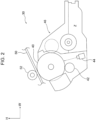
- the toner image forming units 30 for the respective colors basically have the same structure except for toner that is used and include image carriers 40 that rotate and that have a cylindrical shape and chargers 42 that charge the image carriers 40 as illustrated in Fig. 2 .
- the toner image forming units 30 further include exposure devices 44 that radiate exposure light to the image carriers 40 that are charged and form electrostatic latent images and developing devices 46 that develop the electrostatic latent images by using developer Z that contains the toner into the toner images. Consequently, the toner image forming units 30 for the respective colors form images in the respective colors by using the toner in the respective colors.
- the image carriers 40 for the respective colors are in contact with a transfer belt 50 that turns.
- the toner image forming units 30 of yellow(Y), magenta(M), cyan(C), and black(K) are arranged in this order from an upstream position in a direction (see an arrow in the figure) in which the transfer belt 50 turns.
- the transfer unit 32 has a function of transferring the toner images that are formed by the toner image forming units 30 to the print paper P.
- the transfer unit 32 will be described in detail later.
- the fixing device 34 is disposed downstream of a transfer nip NT in a direction in which the print paper P is transported.
- the fixing device 34 heats and presses the toner images that are transferred to the print paper P and fixes the toner images to the print paper P.
- the fixing device 34 includes a heat roller 35 that contains a heater 35a and a pressure roller 36 that faces the heat roller 35 and that is rotated.
- the print paper P passes through a nip region between the heat roller 35 and the pressure roller 36, and the toner images on the print paper P are fixed to the print paper P due to heat and pressure.
- a temperature sensor that is designated by a symbol of 37 detects the surface temperature of the heat roller 35.
- the fixing device 34 includes an electric motor 38 that rotates the heat roller 35 at a predetermined speed.
- the transport unit 14 includes a feed roller 20 that feeds the print paper P that is contained in the container member 18 to the transport path 16 and prevention rollers 22 that prevent multiple pieces of the print paper P fed by the feed roller 20 from being fed.
- the transport unit 14 further includes resist rollers (rollers) 24 that adjust a timing with which the print paper P is fed to the transfer nip NT and the discharge rollers 26 that discharge the print paper P to which the toner images are fixed by the fixing device 34 to a location outside the housing 10a.
- the resist rollers 24 rotate by using rotational force that is produced by an electric motor (an electric actuator) 25.
- the electric motor 25 is controlled by the controller 60.
- a torque detector (an electric current value detector) 25a is connected to the electric motor 25.
- the torque detector 25a detects the torque of the electric motor 25 as an electric current value that flows through the electric motor 25.
- the structure of the torque detector 25a according to the present exemplary embodiment is not particularly limited, provided that the torque of the electric motor 25 is detectable.
- the torque detector 25a may detect the torque of the electric motor 25 as the electric current value that flows through the electric motor 25, may convert the detected electric current value into a voltage value, and may output the voltage value.
- the torque detector 25a may measure a voltage across shunt resistors and may detect an electric current.
- resistors may be provided on a path along which an electric current flows into the electric motor 25, may measure a voltage across the resistors, and may detect the electric current.
- an electric current sensor that includes a hole element may be provided on a path along which an electric current flows into the electric motor 25 and may detect the electric current.
- the torque detector 25a may be a torque detector that detects the torque of the electric motor 25.
- the transfer unit 32 will now be described.
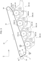
- the transfer belt 50 has not ends and is disposed in a posture such that the periphery (the left-hand periphery in the figure) in the width direction of apparatus is below another periphery.
- the transfer belt 50 is an example of a member that has no ends.
- the drive roller 58 to which driving force is transmitted from a drive source not illustrated rotates, and consequently, the transfer belt 50 turns in the direction (a clockwise direction) of an arrow in the figure.
- the first transfer rollers 52 for the respective colors are disposed downstream of the drive roller 58 and upstream of the winding roller 56 in the direction (referred to below as a "belt turning direction") in which the transfer belt 50 turns.
- the first transfer rollers 52 for the respective colors are in contact with an inner circumferential surface of the transfer belt 50 opposite the image carriers 40 for the respective colors with the transfer belt 50 interposed therebetween.
- the second transfer roller 54 is disposed opposite the winding roller 56 with the transfer belt 50 interposed therebetween.
- the first transfer rollers 52 are examples of a first transfer member.
- the second transfer roller 54 is an example of a second transfer member.
- the first transfer rollers 52 for the respective colors transfer the toner images that are formed on the image carriers 40 for the respective colors to the transfer belt 50 with the transfer belt 50 interposed between the image carriers 40 for the respective colors and the first transfer rollers 52.
- the second transfer roller 54 transfers the toner images that are transferred to the transfer belt 50 by using the first transfer rollers 52 to the print paper P that is transported at the transfer nip NT.
- the transfer voltage is applied to the second transfer roller 54 under constant-current control that is implemented by a constant-current controller 603 described later.
- a detection device that is capable of detecting that the print paper P hits the second transfer roller 54 is provided near the second transfer roller 54 although this is not illustrated. The detection device is connected to the controller 60.
- the application roller 70 is disposed downstream of the first transfer roller 52K and upstream of the second transfer roller 54 in the belt turning direction.
- the application roller 70 is in contact with the inner circumferential surface of the transfer belt 50 and presses the transfer belt 50. Consequently, tension is applied to the transfer belt 50.
- the positioning rollers 64 that are paired are provided so as to interpose all of the first transfer rollers 52 therebetween in the belt turning direction.
- a positioning roller 64a that is disposed upstream of all of the first transfer rollers 52 and a positioning roller 64b that is disposed downstream of all of the first transfer rollers 52 are provided in the belt turning direction.
- the image forming apparatus 10 includes a display unit 59 that includes a touch screen.
- the display unit 59 includes an input unit (an information input unit) 59a and a first display unit 59b.
- a user of the image forming apparatus 10 is able to input information about the kind of the print paper P for a print process by using the input unit 59a.
- Examples of the kind of the print paper P include plain paper and coated paper.
- the information that is inputted by using the input unit 59a is displayed on the first display unit 59b.
- characters "plain paper" are displayed on the first display unit 59b.
- a second display unit (a notification unit or a display unit) 59c displays notification under control of a display unit controller 606 described later.
- the hardware configuration of the controller 60 includes a central processing unit (CPU) or a processor 60A, a read only memory (ROM) 60B, a random access memory (RAM) 60C, a storage 60D, a communication I/F (interface) 60E, and an input-output I/F 60F.
- the CPU 60A, the ROM 60B, the RAM 60C, the storage 60D, the communication I/F 60E, and the input-output I/F 60F are connected to each other so as to be capable of communicating with each other via a bus 60Z.
- the CPU 60A is the central processing unit that runs various programs and that controls components. That is, the CPU 60A reads a program in the ROM 60B or the storage 60D and runs the program by using the RAM 60C as a work area. The CPU 60A controls components and performs various kinds of arithmetic processing in accordance with the programs that are recorded in the ROM 60B or the storage 60D.
- the ROM 60B stores various programs and various kinds of data.
- the RAM 60C that serves as the work area temporarily stores a program or data.
- the storage 60D includes a storage device such as a hard disk drive (HDD) or a solid state drive (SSD) and stores various programs and various kinds of data.
- the communication I/F 60E is an interface for communication with another device.
- Fig. 5 is a block diagram of an example of the functional configuration of the controller 60.
- the functional configuration of the controller 60 includes a rotation controller 601, a thickness presumption unit 602, the constant-current controller 603, a heat capacity presumption unit (a resistance value detector) 604, a temperature controller 605, and the display unit controller 606.
- the CPU 60A reads the programs that are stored in the ROM 60B, and consequently, the rotation controller 601, the thickness presumption unit 602, the constant-current controller 603, the heat capacity presumption unit 604, the temperature controller 605, and the display unit controller 606 function.
- the rotation controller 601 implements rotation control on the electric motor 25 and the electric motor 38.
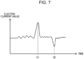
- the thickness presumption unit 602 detects the thickness of the print paper P, based on the electric current value that is detected by the torque detector 25a. As illustrated in Fig. 7 , the electric current value that is detected by the torque detector 25a sharply increases and peaks upward when the print paper P hits the resist rollers 24 and subsequently sharply reduces and peaks downward when the print paper P exits from between the resist rollers 24. In an example illustrated in Fig. 7 , the print paper P hits the resist rollers 24 at a time tl, and the print paper P exits from between the resist rollers 24 at a time t2.
- the CPU 60A detects the thickness of the print paper P by using a variation in the electric current that is detected by the torque detector 25a depending on the thickness of the print paper P.
- the constant-current controller 603 implements the constant-current control under which the transfer voltage is applied to the second transfer roller 54 as described above.
- the heat capacity presumption unit 604 acquires the volume resistivity of the print paper P by using the electric current value and the voltage value of power that is supplied to the second transfer roller 54 under the constant-current control.
- the heat capacity presumption unit 604 presumes the heat capacity of the print paper P by using a heat capacity presumption map 61 (see Fig. 8 ) in which a relationship between the volume resistivity of the print paper P and the heat capacity of the print paper P is defined and the acquired volume resistivity of the print paper P.
- a heat capacity presumption map 61 is an example, and the relationship between the volume resistivity and the heat capacity that is defined in the heat capacity presumption map 61 may be corrected in consideration for temperature and humidity in the housing 10a.
- the temperature controller 605 uses the thickness of the print paper P that is presumed by the thickness presumption unit 602 and the heat capacity of the print paper P that is presumed by the heat capacity presumption unit 604 for a temperature control map 62 illustrated in Fig. 9 that is recorded in the ROM 60B and consequently controls the heater 35a.
- the temperature control map 62 is a two-dimensional map that is defined by using the thickness of the print paper P and the heat capacity of the print paper P.
- the thickness of the print paper P in the temperature control map 62 is defined by using three thicknesses.
- the heat capacity in the temperature control map 62 is defined by using two capacities.
- the thickness of the print paper gradually increases in order of a first thickness, a second thickness, and a third thickness.
- the second heat capacity is larger than the first heat capacity.
- the temperature controller 605 controls the heater 35a such that the target temperature (the temperature that is detected by the temperature sensor 37) of the heat roller 35 becomes a second set temperature.
- the display unit controller 606 controls the display unit 59.
- the display unit controller 606 causes the first display unit 59b to display information that is inputted by the input unit 59a.
- the display unit controller 606 causes the second display unit 59c to display notification. Paper information about the heat capacities and thicknesses of various kinds of print paper is recorded in the ROM 60B. For this reason, in the case where information about the thickness of the print paper P that is inputted by the input unit 59a is included in the paper information, the second display unit 59c displays notification if the information about the thickness that is included in the paper information differs from the thickness that is presumed by the thickness presumption unit 602.
- the second display unit 59c displays notification if the information about the heat capacity that is included in the paper information differs from the heat capacity that is presumed by the heat capacity presumption unit 604.
- the second display unit 59c displays characters the "kind of paper for printing differs from the kind of paper that is inputted".
- the second display unit 59c displays characters the "kind of paper for printing differs from the kind of paper that is inputted".
- the transport unit 14, the resist rollers 24, the electric motor 25, the torque detector 25a, the transfer unit 32, the fixing device 34, the second transfer roller 54, the display unit 59, the controller 60, the heat capacity presumption map 61, and the temperature control map 62 are included in an image forming system 65.
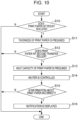
- step S10 the CPU 60A determines whether the print paper P hits the resist rollers 24, based on information that is received from the torque detector 25a.
- the CPU 60A proceeds to S11 and presumes the thickness of the print paper P, based on the information that is received from the torque detector 25a.
- the CPU 60A proceeds to S12 and determines whether the print paper P hits the second transfer roller 54, based on information that is received by the detection device.
- the CPU 60A proceeds to S13 and presumes the heat capacity of the print paper P, based on the volume resistivity of the print paper P and the heat capacity presumption map 61.
- the CPU 60A proceeds to S14, uses information about the thickness of the print paper P that is acquired at S11 and information about the heat capacity of the print paper P that is acquired at S13 for the temperature control map 62, and consequently controls the heater 35a such that the target temperature of the heat roller 35 becomes a set temperature that is defined in the temperature control map 62.
- the CPU 60A proceeds to S15 and determines whether information about the print paper P that is inputted by using the input unit 59a is incorrect.
- the image forming system 65 implements the temperature control on the heat roller 35 (the heater 35a), based on both of the thickness of the print paper P and the heat capacity of the print paper P as described above. For this reason, the image forming system 65 can reduce a failure in the toner images that are fixed to the print paper P unlike the case where the temperature control on the heat roller 35 is implemented based on only the thickness of the print paper P or the heat capacity of the print paper P.
- an image forming system that is thought in a comparative example implements the temperature control on the heat roller 35 (the heater 35a), based on only the thickness of the print paper P.
- temperature control on a heat roller (a heater) in the case where toner images are formed on print paper A (not illustrated) is the same as temperature control on the heat roller (the heater) in the case where toner images are formed on print paper B (not illustrated) that has the same thickness as the print paper A and a heat capacity that differs from that of the print paper A.
- a failure in the toner images that are fixed to at least the print paper A or the print paper B is likely to occur.
- a failure in the toner images that are fixed to the print paper A and the print paper B is likely to be reduced unlike the comparative example.
- the image forming system 65 presumes the thickness of the print paper P by using the resist rollers 24 and the electric motor 25 that are located upstream of the second transfer roller 54, and accordingly, the resist rollers 24 do not distort the toner images on the print paper P.
- the temperature control on the heat roller 35 (the heater 35a) cannot be implemented based on both of the thickness of the print paper P and the heat capacity of the print paper P when the print paper P that is firstly fed from the container member 18 to the heat roller 35 and the pressure roller 36 after a switch of the image forming apparatus 10 is turned on hits the heat roller 35 and the pressure roller 36.
- the image forming system 65 presumes the thickness of the print paper P by using the resist rollers 24 and the electric motor 25 that are located upstream of the second transfer roller 54, and accordingly, the temperature control on the heat roller 35 (the heater 35a) can be implemented based on both of the thickness of the print paper P and the heat capacity of the print paper P also when the print paper P that is firstly fed from the container member 18 to the heat roller 35 and the pressure roller 36 hits the heat roller 35 and the pressure roller 36.
- the image forming system 65 presumes the thickness of the print paper P by using the resist rollers 24 and the electric motor 25 that correspond to existing members in an image forming apparatus. For this reason, the number of the components of the image forming system 65 is smaller than that of a structure that includes a roller exclusively for measuring the thickness of the print paper P.
- the second display unit 59c displays notification in the case where the information about the kind of the print paper P that is inputted into the input unit 59a differs from the presumed kind of the print paper P. For this reason, the image forming system 65 enables the user who inputs the information about the kind of the print paper P into the input unit 59a to recognize that the information about the kind of the print paper P that is inputted is incorrect.
- the image forming apparatus 10 according to the present exemplary embodiment is described above with reference to the drawings.
- the image forming apparatus 10 according to the present exemplary embodiment is not limited by the drawings, and a modification in design may be appropriately made without departing from the spirit of the exemplary embodiment of the disclosure.
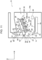
- a basis weight detector 70 is provided in the housing 10a according to the first modification.
- the basis weight detector 70 is located downstream of the feed roller 20 and upstream of the prevention rollers 22.
- the basis weight detector 70 measures the basis weight of the print paper P that is transported by the transport unit 14.
- the basis weight detector 70 may be a device that detects the basis weight by radiating light toward the print paper P and measuring light that passes through the print paper P.
- the basis weight detector 70 may be a device that detects the basis weight by radiating ultrasonic waves toward the print paper P and measuring ultrasonic waves that pass through the print paper P.
- the basis weight detector 70 is connected to the controller 60.
- Fig. 12 illustrates a block diagram that represents an example of the functional configuration of the controller 60 according to the first modification.
- the functional configuration of the controller 60 includes the rotation controller 601, the thickness presumption unit 602, the constant-current controller 603, the heat capacity presumption unit 604, the temperature controller 605, the display unit controller 606, and a water content calculator 607.
- the water content calculator 607 calculates the water content of the print paper P, based on the humidity value and the volume resistivity of the print paper P. For example, the water content calculator 607 calculates the water content of the print paper P by using a map (not illustrated) in which a relationship between the humidity value and the volume resistivity is defined.
- the temperature controller 605 performs a reduction process of reducing the temperature of the heat roller 35 to a temperature lower than a set temperature unlike the case where the water content is less than the first threshold or the basis weight is out of the predetermined range. That is, the temperature controller 605 controls the heater 35a such that the temperature of the heat roller 35 is lower than the set temperature that is acquired based on the temperature control map 62 by a predetermined value. In the case where the print paper P is plain paper, the value of the basis weight of the print paper P is within the predetermined range.
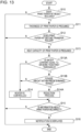
- the CPU 60A according to the first modification repeatedly performs processing in a flowchart in Fig. 13 for every predetermined time.
- Processes at S10 to S13 are the same as those according to the exemplary embodiment.
- the CPU 60A proceeds to S13A and determines whether the water content of the print paper P is equal to or more than the first threshold.
- the image forming system 65 according to the first modification performs the reduction process in the case where the water content of the print paper P is equal to or more than the first threshold, and the value of the basis weight that is acquired by the basis weight detector 70 is within the predetermined range as described above. For this reason, the print paper P is unlikely to curl unlike the case where the temperature of the heat roller 35 is constant regardless of the water content and the basis weight of the print paper P.
- the reduction process is not performed when the water content of the print paper P is equal to or more than the first threshold, water is excessively lost from a surface of the print paper P with which the heat roller 35 comes into contact, a difference between the amounts of water on the front and back of the print paper P increases, and consequently, the print paper P is likely to curl.
- the water content of the print paper P is equal to or more than the first threshold, and the value of the basis weight that is acquired by the basis weight detector 70 is within the predetermined range, the reduction process is performed. Accordingly, the difference between the amounts of water on the front and back of the print paper P is unlikely to increase, and the print paper P is unlikely to curl.
- a temperature-and-humidity sensor 71 is provided in the housing 10a according to the second modification.
- the temperature-and-humidity sensor 71 detects the temperature and the humidity in the housing 10a.
- the humidity that is detected by the temperature-and-humidity sensor 71 is referred to as a humidity value.
- the temperature-and-humidity sensor 71 is connected to the controller 60.
- the temperature controller 605 according to the second modification does not perform the reduction process in the case where the humidity value is equal to or less than a second threshold, and the volume resistivity of the print paper P is equal to or less than a third threshold.
- the temperature controller 605 performs the reduction process in the case where the humidity value is more than the second threshold, or the volume resistivity is more than the third threshold.
- the CPU 60A according to the second modification repeatedly performs processing in a flowchart in Fig. 15 for every predetermined time.
- Processes at S10 to S13 are the same as those according to the exemplary embodiment.
- the CPU 60A proceeds to S13C and determines whether the humidity value is equal to or less than second threshold, and the volume resistivity of the print paper P is equal to or less than the third threshold.
- the image forming system 65 according to the second modification does not perform the reduction process in the case where the humidity value is equal to or less than the second threshold, and the volume resistivity of the print paper P is equal to or less than the third threshold as described above. That is, in the case where the humidity value is equal to or less than the second threshold, it is presumed that the water content of the print paper P is low. For this reason, it is not necessary to perform the reduction process in this case. For this reason, the image forming system 65 according to the second modification can reduce a failure in the toner images that are fixed to the print paper P even when the humidity value is equal to or less than the second threshold, and the volume resistivity of the print paper P is equal to or less than the third threshold unlike the case where the reduction process is performed.
- the image forming system 65 according to the second modification performs the reduction process in the case where the humidity value is more than the second threshold, or in the case where the volume resistivity is more than the third threshold. For this reason, the print paper P is unlikely to curl unlike the case where the temperature of the heat roller 35 is constant regardless of the humidity value and the volume resistivity.
- the image forming apparatus 10 is not limited by intermediate transfer but may be a color or monochrome image forming apparatus by using direct transfer. Also in this case, the heat capacity of the print paper P may be presumed by using a roller for transfer.
- the image forming system 65 may implement the temperature control on the heat roller 35 (the heater 35a), based on the result of detection of the torque detector 25a and the result of detection of the heat capacity presumption unit (the resistance value detector) 604 after the temperature control on the heat roller 35 (the heater 35a) is started based on only the result of detection of the torque detector (the electric current value detector) 25a. That is, the image forming system 65 may implement control on the heater 35a, based on the temperature control map 62 after the heater 35a is controlled such that the temperature of the heat roller 35 becomes the target temperature, based on only the result of detection of the torque detector (the electric current value detector) 25a. According to the modification, a failure in the toner images that are fixed to the print paper P is more likely to be reduced than the case where the temperature control of the heat roller 35 (the heater 35a) is started after the heat capacity and the thickness of the print paper P are presumed.
- the recording medium may differ from the print paper P.
- the recording medium may be a transparent film.
- the image forming system according to (((1)))) can reduce a failure in the toner image on the recording medium unlike the case where the temperature control on the heat roller is implemented based on only the thickness of the recording medium or the heat capacity of the recording medium.
- the number of components is smaller than that of a structure that includes a roller exclusively for measuring the thickness of the recording medium.
- the image forming system enables a user who inputs the information about the kind of the recording medium into the information input unit to recognize that the information about the kind of the recording medium that is inputted is incorrect.
- the image forming system according to (((4))) enables the user to recognize the information about the presumed kind of the recording medium.
- the image forming system according to (((5))) can reduce a failure in the toner image on the recording medium unlike the case where the temperature control of the heat roller is started after the heat capacity and the thickness of the recording medium are presumed.
- the recording medium is unlikely to curl unlike the case where the temperature of the heat roller is constant regardless of the basis weight and the water content.
- the image forming system according to (((7))) can reduce a failure in the toner image on the recording medium even when the value that is detected by the temperature-and-humidity sensor is equal to or less than the second threshold, and the volume resistivity of the recording medium is equal to or less than the third threshold unlike the case where the reduction process is performed.
- the recording medium is unlikely to curl unlike the case where the temperature of the heat roller is constant regardless of the humidity value and the volume resistivity.
Landscapes
- Physics & Mathematics (AREA)
- General Physics & Mathematics (AREA)
- Engineering & Computer Science (AREA)
- Microelectronics & Electronic Packaging (AREA)
- Control Or Security For Electrophotography (AREA)
- Fixing For Electrophotography (AREA)
Abstract
Description
- The present disclosure relates to an image forming system.
-
Japanese Unexamined Patent Application Publication No. 2017-58481 - Accordingly, it is an object of the present disclosure to provide an image forming system that reduces a failure in a toner image that is fixed to a recording medium unlike the case where temperature control on a heat roller is implemented based on only the thickness of the recording medium or the heat capacity of the recording medium.
- According to a first aspect of the present disclosure, there is provided an image forming system including a transport unit that transports a recording medium by using a roller; a transfer unit that applies a transfer voltage by using a transfer body and that transfers a toner image to the recording medium that is transported by the transport unit; a fixing unit that fixes the toner image by using a heat roller to the recording medium to which the toner image is transferred; and a processor configured to: implement temperature control on the heat roller, based on a result of detection of an electric current value detector that detects an electric current value of an electric actuator that rotates the roller and a result of detection of a resistance value detector that detects volume resistivity of the recording medium when the toner image is transferred to the recording medium after the electric current value detector detects the electric current value.
- According to a second aspect of the present disclosure, there is provided the image forming system according to the first aspect in which the roller of the transport unit is a resist roller.
- According to a third aspect of the present disclosure, there is provided the image forming system according to the first aspect or the second aspect that further includes an information input unit into which a user is able to input information about a kind of the recording medium; and a notification unit that is capable of notifying the user in which the processor is configured to: presume the kind of the recording medium, based on the result of detection of the electric current value detector and the result of detection of the resistance value detector, and the notification unit performs a notification operation when it is determined that the presumed kind of the recording medium differs from the kind of the recording medium that is represented by the information that is inputted into the information input unit.
- According to a fourth aspect of the present disclosure, there is provided the image forming system according to the third aspect in which the notification unit is a display unit that is capable of displaying information about the presumed kind of the recording medium.
- According to a fifth aspect of the present disclosure, there is provided the image forming system according to any one of the first aspect to the fourth aspect in which the processor is configured to implement the temperature control on the heat roller, based on the result of detection of the electric current value detector and the result of detection of the resistance value detector after the temperature control on the heat roller is started based on only the result of detection of the electric current value detector.
- According to a sixth aspect of the present disclosure, there is provided the image forming system according to any one of the first aspect to the fifth aspect that further includes a housing that contains the transport unit, the transfer unit, and the fixing unit; a temperature-and-humidity sensor that is provided in the housing; and a basis weight detector that detects a basis weight of the recording medium in which the processor is configured to: presume a water content of the recording medium, based on a humidity value that is detected by the temperature-and-humidity sensor and the volume resistivity of the recording medium; acquire the basis weight of the recording medium from the basis weight detector; and perform a reduction process of reducing temperature of the heat roller in a case where the presumed water content is equal to or more than a first threshold, and the acquired basis weight is within a predetermined range, unlike a case where the water content is less than the first threshold or the basis weight is not within the predetermined range.
- According to a seventh aspect of the present disclosure, there is provided the image forming system according to any one of the first aspect to the sixth aspect that further includes a housing that contains the transport unit, the transfer unit, and the fixing unit; and a temperature-and-humidity sensor that is provided in the housing in which the processor is configured not to perform a reduction process of reducing temperature of the heat roller in a case where a humidity value that is detected by the temperature-and-humidity sensor is equal to or less than a second threshold, and the volume resistivity of the recording medium is equal to or less than a third threshold, unlike a case where the humidity value is more than the second threshold or the volume resistivity of the recording medium is more than the third threshold.
- According to an eighth aspect of the present disclosure, there is provided the image forming system according to the seventh aspect in which the processor is configured to perform the reduction process in the case where the humidity value is more than the second threshold, or the volume resistivity is more than the third threshold.
- The image forming system according to the first aspect of the present disclosure can reduce a failure in the toner image on the recording medium unlike the case where the temperature control on the heat roller is implemented based on only the thickness of the recording medium or the heat capacity of the recording medium.
- As for the image forming system according to the second aspect of the present disclosure, the number of components is smaller than that of a structure that includes a roller exclusively for measuring the thickness of the recording medium.
- The image forming system according to the third aspect of the present disclosure enables a user who inputs the information about the kind of the recording medium into the information input unit to recognize that the information about the kind of the recording medium that is inputted is incorrect.
- The image forming system according to the fourth aspect of the present disclosure enables the user to recognize the information about the presumed kind of the recording medium.
- The image forming system according to the fifth aspect of the present disclosure can reduce a failure in the toner image on the recording medium unlike the case where the temperature control of the heat roller is started after the heat capacity and the thickness of the recording medium are presumed.
- As for the image forming system according to the sixth aspect of the present disclosure, the recording medium is unlikely to curl unlike the case where the temperature of the heat roller is constant regardless of the basis weight and the water content.
- The image forming system according to the seventh aspect of the present disclosure can reduce a failure in the toner image on the recording medium even when the value that is detected by the temperature-and-humidity sensor is equal to or less than the second threshold, and the volume resistivity of the recording medium is equal to or less than the third threshold unlike the case where the reduction process is performed.
- As for the image forming system according to the eighth aspect of the present disclosure, the recording medium is unlikely to curl unlike the case where the temperature of the heat roller is constant regardless of the humidity value and the volume resistivity.
- Exemplary embodiments of the present disclosure will be described in detail based on the following figures, wherein:
-
Fig. 1 schematically illustrates the structure of an image forming apparatus that includes an image forming system according to an exemplary embodiment of the present disclosure; -
Fig. 2 illustrates the structure of a toner image forming unit of the image forming apparatus according to the exemplary embodiment of the present disclosure; -
Fig. 3 is a front view of a transfer unit according to the exemplary embodiment of the present disclosure in a color mode; -
Fig. 4 is a control block diagram of the hardware configuration of the image forming apparatus; -
Fig. 5 is a functional block diagram of the hardware configuration; -
Fig. 6 illustrates a display unit; -
Fig. 7 illustrates an example of an electric current that is detected by a torque detector; -
Fig. 8 illustrates a heat capacity presumption map; -
Fig. 9 illustrates a temperature control map; -
Fig. 10 is a flowchart illustrating processing that is performed by a CPU; -
Fig. 11 illustrates a first modification and corresponds toFig. 1 ; -
Fig. 12 is a functional block diagram of a hardware configuration according to the first modification; -
Fig. 13 is flowchart illustrating processing that is performed by the CPU according to the first modification; -
Fig. 14 illustrates a second modification and corresponds toFig. 1 ; and -
Fig. 15 is a flowchart illustrating processing that is performed by the CPU according to the second modification. - An example of an image forming system according to an exemplary embodiment of the present disclosure will be described with reference to
Fig. 1 to Fig. 10 . In the drawings, an arrow H represents a vertical direction, that is, an up-down direction of apparatus, and an arrow W represents a horizontal direction, that is, a width direction of apparatus. - As illustrated in
Fig. 1 , theimage forming apparatus 10 includes animage forming unit 12 that forms toner images by using an electrophotographic system and atransport unit 14 that transports print paper (a recording medium) P that serves as a recording medium along atransport path 16. Theimage forming apparatus 10 includes acontainer member 18 that contains the print paper P and acontroller 60 that controls the entire apparatus. - As for the
image forming apparatus 10, thetransport unit 14 transports the print paper P that is contained in thecontainer member 18 along thetransport path 16. The toner images that are formed by theimage forming unit 12 are formed on the print paper P that is transported, and the print paper P on which the toner images are formed is discharged to a location outside ahousing 10a by usingdischarge rollers 26 described later. - As illustrated in
Fig. 1 , theimage forming unit 12 includes multiple tonerimage forming units 30 that form toner images in respective colors and atransfer unit 32 that transfers the toner images that are formed by the tonerimage forming units 30 to the print paper P. Theimage forming unit 12 includes a fixing device (a fixing unit) 34 that fixes, to the print paper P, the toner images that are transferred to the print paper P by using thetransfer unit 32. - The multiple toner
image forming units 30 are provided so as to form the toner images in the respective colors. According to the present exemplary embodiment, tonerimage forming units - The toner
image forming units 30 for the respective colors basically have the same structure except for toner that is used and includeimage carriers 40 that rotate and that have a cylindrical shape andchargers 42 that charge theimage carriers 40 as illustrated inFig. 2 . The tonerimage forming units 30 further includeexposure devices 44 that radiate exposure light to theimage carriers 40 that are charged and form electrostatic latent images and developingdevices 46 that develop the electrostatic latent images by using developer Z that contains the toner into the toner images. Consequently, the tonerimage forming units 30 for the respective colors form images in the respective colors by using the toner in the respective colors. - As illustrated in
Fig. 1 , theimage carriers 40 for the respective colors are in contact with atransfer belt 50 that turns. The tonerimage forming units 30 of yellow(Y), magenta(M), cyan(C), and black(K) are arranged in this order from an upstream position in a direction (see an arrow in the figure) in which thetransfer belt 50 turns. - The
transfer unit 32 has a function of transferring the toner images that are formed by the tonerimage forming units 30 to the print paper P. Thetransfer unit 32 will be described in detail later. - As illustrated in
Fig. 1 , thefixing device 34 is disposed downstream of a transfer nip NT in a direction in which the print paper P is transported. The fixingdevice 34 heats and presses the toner images that are transferred to the print paper P and fixes the toner images to the print paper P. More specifically, the fixingdevice 34 includes aheat roller 35 that contains aheater 35a and apressure roller 36 that faces theheat roller 35 and that is rotated. The print paper P passes through a nip region between theheat roller 35 and thepressure roller 36, and the toner images on the print paper P are fixed to the print paper P due to heat and pressure. A temperature sensor that is designated by a symbol of 37 detects the surface temperature of theheat roller 35. The fixingdevice 34 includes anelectric motor 38 that rotates theheat roller 35 at a predetermined speed. - As illustrated in
Fig. 1 , thetransport unit 14 includes afeed roller 20 that feeds the print paper P that is contained in thecontainer member 18 to thetransport path 16 andprevention rollers 22 that prevent multiple pieces of the print paper P fed by thefeed roller 20 from being fed. Thetransport unit 14 further includes resist rollers (rollers) 24 that adjust a timing with which the print paper P is fed to the transfer nip NT and thedischarge rollers 26 that discharge the print paper P to which the toner images are fixed by the fixingdevice 34 to a location outside thehousing 10a. - The resist
rollers 24 rotate by using rotational force that is produced by an electric motor (an electric actuator) 25. Theelectric motor 25 is controlled by thecontroller 60. A torque detector (an electric current value detector) 25a is connected to theelectric motor 25. - The
torque detector 25a detects the torque of theelectric motor 25 as an electric current value that flows through theelectric motor 25. - The structure of the
torque detector 25a according to the present exemplary embodiment is not particularly limited, provided that the torque of theelectric motor 25 is detectable. For example, thetorque detector 25a may detect the torque of theelectric motor 25 as the electric current value that flows through theelectric motor 25, may convert the detected electric current value into a voltage value, and may output the voltage value. Thetorque detector 25a may measure a voltage across shunt resistors and may detect an electric current. For example, as for thetorque detector 25a, resistors may be provided on a path along which an electric current flows into theelectric motor 25, may measure a voltage across the resistors, and may detect the electric current. For example, as for thetorque detector 25a, an electric current sensor that includes a hole element may be provided on a path along which an electric current flows into theelectric motor 25 and may detect the electric current. For example, thetorque detector 25a may be a torque detector that detects the torque of theelectric motor 25. - The
transfer unit 32 will now be described. - As illustrated in
Fig. 3 , thetransfer unit 32 includes thetransfer belt 50 andfirst transfer rollers 52 that are disposed opposite therespective image carriers 40 for the respective colors with thetransfer belt 50 interposed therebetween and transfers the toner images in the respective colors that are formed by theimage carriers 40 to thetransfer belt 50. Thetransfer unit 32 also includes a contact-separation unit (not illustrated) that moves at least one of thefirst transfer rollers 52 among the multiplefirst transfer rollers 52 and brings thetransfer belt 50 and theimage carriers 40 into contact with each other or separates thetransfer belt 50 and theimage carriers 40 from each other. - The
transfer unit 32 further includes a windingroller 56 around which thetransfer belt 50 is wound, adrive roller 58, around which thetransfer belt 50 is wound, which transmits rotational force to thetransfer belt 50, andpositioning rollers 64 that determine the positions of portions of thetransfer belt 50 at which the toner images are transferred. Thetransfer unit 32 also includes anapplication roller 70 that applies tension to thetransfer belt 50. - The
transfer unit 32 further includes asecond transfer roller 54 that is disposed opposite the windingroller 56 with thetransfer belt 50 interposed therebetween and that transfers the toner images that are transferred to thetransfer belt 50 to the print paper P. The transfer nip NT at which the toner images are transferred to the print paper P is formed between thesecond transfer roller 54 and thetransfer belt 50. - As illustrated in
Fig. 3 , thetransfer belt 50 has not ends and is disposed in a posture such that the periphery (the left-hand periphery in the figure) in the width direction of apparatus is below another periphery. Thetransfer belt 50 is an example of a member that has no ends. - The axial direction of the winding
roller 56 coincides with a depth direction of apparatus. A peripheral portion of thetransfer belt 50 in the width direction of apparatus is wound around the windingroller 56. The axial direction of thedrive roller 58 coincides with the depth direction of apparatus. Another peripheral portion of thetransfer belt 50 in the width direction of apparatus is wound around thedrive roller 58. - With this structure, the
drive roller 58 to which driving force is transmitted from a drive source not illustrated rotates, and consequently, thetransfer belt 50 turns in the direction (a clockwise direction) of an arrow in the figure. - As illustrated in
Fig. 3 , thefirst transfer rollers 52 for the respective colors are disposed downstream of thedrive roller 58 and upstream of the windingroller 56 in the direction (referred to below as a "belt turning direction") in which thetransfer belt 50 turns. Thefirst transfer rollers 52 for the respective colors are in contact with an inner circumferential surface of thetransfer belt 50 opposite theimage carriers 40 for the respective colors with thetransfer belt 50 interposed therebetween. Thesecond transfer roller 54 is disposed opposite the windingroller 56 with thetransfer belt 50 interposed therebetween. Thefirst transfer rollers 52 are examples of a first transfer member. Thesecond transfer roller 54 is an example of a second transfer member. - With this structure, the
first transfer rollers 52 for the respective colors transfer the toner images that are formed on theimage carriers 40 for the respective colors to thetransfer belt 50 with thetransfer belt 50 interposed between theimage carriers 40 for the respective colors and thefirst transfer rollers 52. Thesecond transfer roller 54 transfers the toner images that are transferred to thetransfer belt 50 by using thefirst transfer rollers 52 to the print paper P that is transported at the transfer nip NT. The transfer voltage is applied to thesecond transfer roller 54 under constant-current control that is implemented by a constant-current controller 603 described later. A detection device that is capable of detecting that the print paper P hits thesecond transfer roller 54 is provided near thesecond transfer roller 54 although this is not illustrated. The detection device is connected to thecontroller 60. - As illustrated in
Fig. 3 , theapplication roller 70 is disposed downstream of thefirst transfer roller 52K and upstream of thesecond transfer roller 54 in the belt turning direction. Theapplication roller 70 is in contact with the inner circumferential surface of thetransfer belt 50 and presses thetransfer belt 50. Consequently, tension is applied to thetransfer belt 50. - As illustrated in
Fig. 3 , thepositioning rollers 64 that are paired are provided so as to interpose all of thefirst transfer rollers 52 therebetween in the belt turning direction. Specifically, apositioning roller 64a that is disposed upstream of all of thefirst transfer rollers 52 and apositioning roller 64b that is disposed downstream of all of thefirst transfer rollers 52 are provided in the belt turning direction. - As illustrated in
Fig. 6 , theimage forming apparatus 10 includes adisplay unit 59 that includes a touch screen. Thedisplay unit 59 includes an input unit (an information input unit) 59a and afirst display unit 59b. For example, a user of theimage forming apparatus 10 is able to input information about the kind of the print paper P for a print process by using theinput unit 59a. Examples of the kind of the print paper P include plain paper and coated paper. The information that is inputted by using theinput unit 59a is displayed on thefirst display unit 59b. For example, in the case where the user inputs information that represents plain paper by using theinput unit 59a, characters "plain paper" are displayed on thefirst display unit 59b. A second display unit (a notification unit or a display unit) 59c displays notification under control of adisplay unit controller 606 described later. - As illustrated in
Fig. 4 , the hardware configuration of thecontroller 60 includes a central processing unit (CPU) or aprocessor 60A, a read only memory (ROM) 60B, a random access memory (RAM) 60C, astorage 60D, a communication I/F (interface) 60E, and an input-output I/F 60F. TheCPU 60A, theROM 60B, theRAM 60C, thestorage 60D, the communication I/F 60E, and the input-output I/F 60F are connected to each other so as to be capable of communicating with each other via a bus 60Z. - The
CPU 60A is the central processing unit that runs various programs and that controls components. That is, theCPU 60A reads a program in theROM 60B or thestorage 60D and runs the program by using theRAM 60C as a work area. TheCPU 60A controls components and performs various kinds of arithmetic processing in accordance with the programs that are recorded in theROM 60B or thestorage 60D. - The
ROM 60B stores various programs and various kinds of data. TheRAM 60C that serves as the work area temporarily stores a program or data. Thestorage 60D includes a storage device such as a hard disk drive (HDD) or a solid state drive (SSD) and stores various programs and various kinds of data. The communication I/F 60E is an interface for communication with another device. -
Fig. 5 is a block diagram of an example of the functional configuration of thecontroller 60. The functional configuration of thecontroller 60 includes arotation controller 601, athickness presumption unit 602, the constant-current controller 603, a heat capacity presumption unit (a resistance value detector) 604, atemperature controller 605, and thedisplay unit controller 606. TheCPU 60A reads the programs that are stored in theROM 60B, and consequently, therotation controller 601, thethickness presumption unit 602, the constant-current controller 603, the heatcapacity presumption unit 604, thetemperature controller 605, and thedisplay unit controller 606 function. - The
rotation controller 601 implements rotation control on theelectric motor 25 and theelectric motor 38. - The
thickness presumption unit 602 detects the thickness of the print paper P, based on the electric current value that is detected by thetorque detector 25a. As illustrated inFig. 7 , the electric current value that is detected by thetorque detector 25a sharply increases and peaks upward when the print paper P hits the resistrollers 24 and subsequently sharply reduces and peaks downward when the print paper P exits from between the resistrollers 24. In an example illustrated inFig. 7 , the print paper P hits the resistrollers 24 at a time tl, and the print paper P exits from between the resistrollers 24 at a time t2. As for the electric current that is detected by thetorque detector 25a, peak values when the print paper P hits the resistrollers 24 and exits and a value when the print paper P passes through the resistrollers 24 change depending on the thickness of the print paper P. As for a detection function according to the present exemplary embodiment, theCPU 60A detects the thickness of the print paper P by using a variation in the electric current that is detected by thetorque detector 25a depending on the thickness of the print paper P. - The constant-
current controller 603 implements the constant-current control under which the transfer voltage is applied to thesecond transfer roller 54 as described above. - The heat
capacity presumption unit 604 acquires the volume resistivity of the print paper P by using the electric current value and the voltage value of power that is supplied to thesecond transfer roller 54 under the constant-current control. The heatcapacity presumption unit 604 presumes the heat capacity of the print paper P by using a heat capacity presumption map 61 (seeFig. 8 ) in which a relationship between the volume resistivity of the print paper P and the heat capacity of the print paper P is defined and the acquired volume resistivity of the print paper P. As clear fromFig. 8 , the heat capacity of the print paper P and the volume resistivity are substantially proportional to each other. The heatcapacity presumption map 61 is an example, and the relationship between the volume resistivity and the heat capacity that is defined in the heatcapacity presumption map 61 may be corrected in consideration for temperature and humidity in thehousing 10a. - The
temperature controller 605 uses the thickness of the print paper P that is presumed by thethickness presumption unit 602 and the heat capacity of the print paper P that is presumed by the heatcapacity presumption unit 604 for atemperature control map 62 illustrated inFig. 9 that is recorded in theROM 60B and consequently controls theheater 35a. Thetemperature control map 62 is a two-dimensional map that is defined by using the thickness of the print paper P and the heat capacity of the print paper P. The thickness of the print paper P in thetemperature control map 62 is defined by using three thicknesses. The heat capacity in thetemperature control map 62 is defined by using two capacities. The thickness of the print paper gradually increases in order of a first thickness, a second thickness, and a third thickness. The second heat capacity is larger than the first heat capacity. For example, in the case where the presumed thickness of the print paper P is the "second thickness", and the presumed heat capacity of the print paper P is the "first heat capacity", thetemperature controller 605 controls theheater 35a such that the target temperature (the temperature that is detected by the temperature sensor 37) of theheat roller 35 becomes a second set temperature. - The
display unit controller 606 controls thedisplay unit 59. For example, thedisplay unit controller 606 causes thefirst display unit 59b to display information that is inputted by theinput unit 59a. - In the case where the information about the kind of the print paper P that is inputted by the
input unit 59a differs from the presumed kind of the print paper P, thedisplay unit controller 606 causes thesecond display unit 59c to display notification. Paper information about the heat capacities and thicknesses of various kinds of print paper is recorded in theROM 60B. For this reason, in the case where information about the thickness of the print paper P that is inputted by theinput unit 59a is included in the paper information, thesecond display unit 59c displays notification if the information about the thickness that is included in the paper information differs from the thickness that is presumed by thethickness presumption unit 602. In the case where information about the heat capacity of the print paper P that is inputted by theinput unit 59a is included in the paper information, thesecond display unit 59c displays notification if the information about the heat capacity that is included in the paper information differs from the heat capacity that is presumed by the heatcapacity presumption unit 604. For example, in the case where information about the print paper P that is inputted by theinput unit 59a is paper that has a predetermined thickness, and the print paper P that is presumed by thethickness presumption unit 602 is paper that has a thickness greater than the predetermined thickness, thesecond display unit 59c displays characters the "kind of paper for printing differs from the kind of paper that is inputted". In the case where the heat capacity of the print paper P that is inputted by theinput unit 59a has a predetermined value, and the heat capacity of the print paper P that is presumed by the heatcapacity presumption unit 604 is greater than the predetermined value, thesecond display unit 59c displays characters the "kind of paper for printing differs from the kind of paper that is inputted". - Among the components described above, the
transport unit 14, the resistrollers 24, theelectric motor 25, thetorque detector 25a, thetransfer unit 32, the fixingdevice 34, thesecond transfer roller 54, thedisplay unit 59, thecontroller 60, the heatcapacity presumption map 61, and thetemperature control map 62 are included in animage forming system 65. - The actions of the
image forming apparatus 10 thus configured will now be described with reference to a flowchart inFig. 10 . TheCPU 60A repeatedly performs processing in the flowchart inFig. 10 for every predetermined time. - As a step S10 (in the following description, the characters "step" are omitted), the
CPU 60A determines whether the print paper P hits the resistrollers 24, based on information that is received from thetorque detector 25a. - If determination at S10 is Yes, the
CPU 60A proceeds to S11 and presumes the thickness of the print paper P, based on the information that is received from thetorque detector 25a. - In the case where a process at S11 ends, the
CPU 60A proceeds to S12 and determines whether the print paper P hits thesecond transfer roller 54, based on information that is received by the detection device. - If determination at S12 is Yes, the
CPU 60A proceeds to S13 and presumes the heat capacity of the print paper P, based on the volume resistivity of the print paper P and the heatcapacity presumption map 61. - In the case where a process at S13 ends, the
CPU 60A proceeds to S14, uses information about the thickness of the print paper P that is acquired at S11 and information about the heat capacity of the print paper P that is acquired at S13 for thetemperature control map 62, and consequently controls theheater 35a such that the target temperature of theheat roller 35 becomes a set temperature that is defined in thetemperature control map 62. - In the case where a process at S14 ends, the
CPU 60A proceeds to S15 and determines whether information about the print paper P that is inputted by using theinput unit 59a is incorrect. - If determination at S15 is Yes, the
CPU 60A proceeds to S16, and thesecond display unit 59c displays notification. - If the determination at S10, S12, and S15 is No, or when a process at S16 ends, the
CPU 60A ends the processing in the flowchart inFig. 10 once. - The
image forming system 65 according to the present exemplary embodiment implements the temperature control on the heat roller 35 (theheater 35a), based on both of the thickness of the print paper P and the heat capacity of the print paper P as described above. For this reason, theimage forming system 65 can reduce a failure in the toner images that are fixed to the print paper P unlike the case where the temperature control on theheat roller 35 is implemented based on only the thickness of the print paper P or the heat capacity of the print paper P. For example, an image forming system that is thought in a comparative example implements the temperature control on the heat roller 35 (theheater 35a), based on only the thickness of the print paper P. As for the image forming system in the comparative example, temperature control on a heat roller (a heater) in the case where toner images are formed on print paper A (not illustrated) is the same as temperature control on the heat roller (the heater) in the case where toner images are formed on print paper B (not illustrated) that has the same thickness as the print paper A and a heat capacity that differs from that of the print paper A. For this reason, as for the image forming system in the comparative example, a failure in the toner images that are fixed to at least the print paper A or the print paper B is likely to occur. As for theimage forming system 65 according to the present exemplary embodiment, a failure in the toner images that are fixed to the print paper A and the print paper B is likely to be reduced unlike the comparative example. - In the case where the thickness of the print paper P is presumed by using a roller that is provided downstream of the
second transfer roller 54 and upstream of theheat roller 35 and thepressure roller 36 and an electric actuator that applies driving force to the roller, there is a possibility that the roller distorts the toner images on the print paper P. However, theimage forming system 65 according to the present exemplary embodiment presumes the thickness of the print paper P by using the resistrollers 24 and theelectric motor 25 that are located upstream of thesecond transfer roller 54, and accordingly, the resistrollers 24 do not distort the toner images on the print paper P. - In the case where the thickness of the print paper P is presumed by using the
heat roller 35 and theelectric motor 38, the temperature control on the heat roller 35 (theheater 35a) cannot be implemented based on both of the thickness of the print paper P and the heat capacity of the print paper P when the print paper P that is firstly fed from thecontainer member 18 to theheat roller 35 and thepressure roller 36 after a switch of theimage forming apparatus 10 is turned on hits theheat roller 35 and thepressure roller 36. However, theimage forming system 65 according to the present exemplary embodiment presumes the thickness of the print paper P by using the resistrollers 24 and theelectric motor 25 that are located upstream of thesecond transfer roller 54, and accordingly, the temperature control on the heat roller 35 (theheater 35a) can be implemented based on both of the thickness of the print paper P and the heat capacity of the print paper P also when the print paper P that is firstly fed from thecontainer member 18 to theheat roller 35 and thepressure roller 36 hits theheat roller 35 and thepressure roller 36. - The
image forming system 65 presumes the thickness of the print paper P by using the resistrollers 24 and theelectric motor 25 that correspond to existing members in an image forming apparatus. For this reason, the number of the components of theimage forming system 65 is smaller than that of a structure that includes a roller exclusively for measuring the thickness of the print paper P. - As for the
image forming system 65, thesecond display unit 59c displays notification in the case where the information about the kind of the print paper P that is inputted into theinput unit 59a differs from the presumed kind of the print paper P. For this reason, theimage forming system 65 enables the user who inputs the information about the kind of the print paper P into theinput unit 59a to recognize that the information about the kind of the print paper P that is inputted is incorrect. - The
image forming apparatus 10 according to the present exemplary embodiment is described above with reference to the drawings. Theimage forming apparatus 10 according to the present exemplary embodiment, however, is not limited by the drawings, and a modification in design may be appropriately made without departing from the spirit of the exemplary embodiment of the disclosure. - For example, the exemplary embodiment of the disclosure may be carried out according to a first modification illustrated in
Fig. 11 to Fig. 13 . As illustrated inFig. 11 , abasis weight detector 70 is provided in thehousing 10a according to the first modification. Thebasis weight detector 70 is located downstream of thefeed roller 20 and upstream of theprevention rollers 22. Thebasis weight detector 70 measures the basis weight of the print paper P that is transported by thetransport unit 14. For example, thebasis weight detector 70 may be a device that detects the basis weight by radiating light toward the print paper P and measuring light that passes through the print paper P. Thebasis weight detector 70 may be a device that detects the basis weight by radiating ultrasonic waves toward the print paper P and measuring ultrasonic waves that pass through the print paper P. Thebasis weight detector 70 is connected to thecontroller 60. -
Fig. 12 illustrates a block diagram that represents an example of the functional configuration of thecontroller 60 according to the first modification. The functional configuration of thecontroller 60 includes therotation controller 601, thethickness presumption unit 602, the constant-current controller 603, the heatcapacity presumption unit 604, thetemperature controller 605, thedisplay unit controller 606, and awater content calculator 607. Thewater content calculator 607 calculates the water content of the print paper P, based on the humidity value and the volume resistivity of the print paper P. For example, thewater content calculator 607 calculates the water content of the print paper P by using a map (not illustrated) in which a relationship between the humidity value and the volume resistivity is defined. - In the case where the calculated water content is equal to or more than a predetermined first threshold, and the value of the basis weight that is acquired by the
basis weight detector 70 is within a predetermined range, thetemperature controller 605 performs a reduction process of reducing the temperature of theheat roller 35 to a temperature lower than a set temperature unlike the case where the water content is less than the first threshold or the basis weight is out of the predetermined range. That is, thetemperature controller 605 controls theheater 35a such that the temperature of theheat roller 35 is lower than the set temperature that is acquired based on thetemperature control map 62 by a predetermined value. In the case where the print paper P is plain paper, the value of the basis weight of the print paper P is within the predetermined range. - The
CPU 60A according to the first modification repeatedly performs processing in a flowchart inFig. 13 for every predetermined time. - Processes at S10 to S13 are the same as those according to the exemplary embodiment.
- In the case where the process at S13 ends, the
CPU 60A proceeds to S13A and determines whether the water content of the print paper P is equal to or more than the first threshold. - If determination at S13A is Yes, the
CPU 60A proceeds to S13B and determines whether the value of the basis weight of the print paper P is within the predetermined range. - If determination at S13B is Yes, the
CPU 60A proceeds to S14A and implements the temperature control on theheat roller 35 while performing the reduction process. - If the determination at S13B is No, the
CPU 60A proceeds to S14. - In the case where a process at S14 or S14A ends, the
CPU 60A proceeds to S15. - The
image forming system 65 according to the first modification performs the reduction process in the case where the water content of the print paper P is equal to or more than the first threshold, and the value of the basis weight that is acquired by thebasis weight detector 70 is within the predetermined range as described above. For this reason, the print paper P is unlikely to curl unlike the case where the temperature of theheat roller 35 is constant regardless of the water content and the basis weight of the print paper P. That is, for example, in the case where the reduction process is not performed when the water content of the print paper P is equal to or more than the first threshold, water is excessively lost from a surface of the print paper P with which theheat roller 35 comes into contact, a difference between the amounts of water on the front and back of the print paper P increases, and consequently, the print paper P is likely to curl. According to the first modification, the water content of the print paper P is equal to or more than the first threshold, and the value of the basis weight that is acquired by thebasis weight detector 70 is within the predetermined range, the reduction process is performed. Accordingly, the difference between the amounts of water on the front and back of the print paper P is unlikely to increase, and the print paper P is unlikely to curl. - The exemplary embodiment of the disclosure may be carried out according to a second modification illustrated in
Fig. 14 andFig. 15 . As illustrated inFig. 14 , a temperature-and-humidity sensor 71 is provided in thehousing 10a according to the second modification. The temperature-and-humidity sensor 71 detects the temperature and the humidity in thehousing 10a. In the following description, the humidity that is detected by the temperature-and-humidity sensor 71 is referred to as a humidity value. The temperature-and-humidity sensor 71 is connected to thecontroller 60. - The
temperature controller 605 according to the second modification does not perform the reduction process in the case where the humidity value is equal to or less than a second threshold, and the volume resistivity of the print paper P is equal to or less than a third threshold. Thetemperature controller 605 performs the reduction process in the case where the humidity value is more than the second threshold, or the volume resistivity is more than the third threshold. - The
CPU 60A according to the second modification repeatedly performs processing in a flowchart inFig. 15 for every predetermined time. - Processes at S10 to S13 are the same as those according to the exemplary embodiment.
- In the case where the process at S13 ends, the
CPU 60A proceeds to S13C and determines whether the humidity value is equal to or less than second threshold, and the volume resistivity of the print paper P is equal to or less than the third threshold. - If determination at S13C is Yes, the
CPU 60A proceeds to S14. If the determination at S13C is No, theCPU 60A proceeds to S14A. - In the case where the process at S14 or S14A ends, the
CPU 60A proceeds to S15. - The
image forming system 65 according to the second modification does not perform the reduction process in the case where the humidity value is equal to or less than the second threshold, and the volume resistivity of the print paper P is equal to or less than the third threshold as described above. That is, in the case where the humidity value is equal to or less than the second threshold, it is presumed that the water content of the print paper P is low. For this reason, it is not necessary to perform the reduction process in this case. For this reason, theimage forming system 65 according to the second modification can reduce a failure in the toner images that are fixed to the print paper P even when the humidity value is equal to or less than the second threshold, and the volume resistivity of the print paper P is equal to or less than the third threshold unlike the case where the reduction process is performed. - The
image forming system 65 according to the second modification performs the reduction process in the case where the humidity value is more than the second threshold, or in the case where the volume resistivity is more than the third threshold. For this reason, the print paper P is unlikely to curl unlike the case where the temperature of theheat roller 35 is constant regardless of the humidity value and the volume resistivity. - The
image forming apparatus 10 is not limited by intermediate transfer but may be a color or monochrome image forming apparatus by using direct transfer. Also in this case, the heat capacity of the print paper P may be presumed by using a roller for transfer. - The
image forming system 65 may implement the temperature control on the heat roller 35 (theheater 35a), based on the result of detection of thetorque detector 25a and the result of detection of the heat capacity presumption unit (the resistance value detector) 604 after the temperature control on the heat roller 35 (theheater 35a) is started based on only the result of detection of the torque detector (the electric current value detector) 25a. That is, theimage forming system 65 may implement control on theheater 35a, based on thetemperature control map 62 after theheater 35a is controlled such that the temperature of theheat roller 35 becomes the target temperature, based on only the result of detection of the torque detector (the electric current value detector) 25a. According to the modification, a failure in the toner images that are fixed to the print paper P is more likely to be reduced than the case where the temperature control of the heat roller 35 (theheater 35a) is started after the heat capacity and the thickness of the print paper P are presumed. - The recording medium may differ from the print paper P. For example, the recording medium may be a transparent film.
- The foregoing description of the exemplary embodiments of the present disclosure has been provided for the purposes of illustration and description. It is not intended to be exhaustive or to limit the disclosure to the precise forms disclosed. Obviously, many modifications and variations will be apparent to practitioners skilled in the art. The embodiments were chosen and described in order to best explain the principles of the disclosure and its practical applications, thereby enabling others skilled in the art to understand the disclosure for various embodiments and with the various modifications as are suited to the particular use contemplated. It is intended that the scope of the disclosure be defined by the following claims and their equivalents.
-
- (((1))) An image forming system includes a transport unit that transports a recording medium by using a roller; a transfer unit that applies a transfer voltage by using a transfer body and that transfers a toner image to the recording medium that is transported by the transport unit; a fixing unit that fixes the toner image by using a heat roller to the recording medium to which the toner image is transferred; and a processor configured to: implement temperature control on the heat roller, based on a result of detection of an electric current value detector that detects an electric current value of an electric actuator that rotates the roller and a result of detection of a resistance value detector that detects volume resistivity of the recording medium when the toner image is transferred to the recording medium after the electric current value detector detects the electric current value.
- (((2))) As for the image forming system described in (((1))), the roller of the transport unit is a resist roller.
- (((3))) The image forming system described in ((((1))) or ((2))) further includes an information input unit into which a user is able to input information about a kind of the recording medium; and a notification unit that is capable of notifying the user in which the processor is configured to: presume the kind of the recording medium, based on the result of detection of the electric current value detector and the result of detection of the resistance value detector, and the notification unit performs a notification operation when it is determined that the presumed kind of the recording medium differs from the kind of the recording medium that is represented by the information that is inputted into the information input unit.
- (((4))) As for the image forming system described in (((3))), the notification unit is a display unit that is capable of displaying information about the presumed kind of the recording medium.
- (((5))) As for the image forming system described in any one of (((1))) to (((4))), the processor is configured to implement the temperature control on the heat roller, based on the result of detection of the electric current value detector and the result of detection of the resistance value detector after the temperature control on the heat roller is started based on only the result of detection of the electric current value detector.
- (((6))) The image forming system described in any one of (((1))) to (((5))) further includes a housing that contains the transport unit, the transfer unit, and the fixing unit; a temperature-and-humidity sensor that is provided in the housing; and a basis weight detector that detects a basis weight of the recording medium in which the processor is configured to: presume a water content of the recording medium, based on a humidity value that is detected by the temperature-and-humidity sensor and the volume resistivity of the recording medium; acquire the basis weight of the recording medium from the basis weight detector; and perform a reduction process of reducing temperature of the heat roller in a case where the presumed water content is equal to or more than a first threshold, and the acquired basis weight is within a predetermined range, unlike a case where the water content is less than the first threshold or the basis weight is not within the predetermined range.
- (((7))) The image forming system described in any one of (((1))) to (((6))) further includes a housing that contains the transport unit, the transfer unit, and the fixing unit; and a temperature-and-humidity sensor that is provided in the housing in which the processor is configured not to perform a reduction process of reducing temperature of the heat roller in a case where a humidity value that is detected by the temperature-and-humidity sensor is equal to or less than a second threshold, and the volume resistivity of the recording medium is equal to or less than a third threshold, unlike a case where the humidity value is more than the second threshold or the volume resistivity of the recording medium is more than the third threshold.
- (((8))) As for the image forming system described in (((7))), the processor is configured to perform the reduction process in the case where the humidity value is more than the second threshold, or the volume resistivity is more than the third threshold.
- The image forming system according to (((1)))) can reduce a failure in the toner image on the recording medium unlike the case where the temperature control on the heat roller is implemented based on only the thickness of the recording medium or the heat capacity of the recording medium.
- As for the image forming system according to (((2))), the number of components is smaller than that of a structure that includes a roller exclusively for measuring the thickness of the recording medium.
- The image forming system according to (((3))) enables a user who inputs the information about the kind of the recording medium into the information input unit to recognize that the information about the kind of the recording medium that is inputted is incorrect.
- The image forming system according to (((4))) enables the user to recognize the information about the presumed kind of the recording medium.
- The image forming system according to (((5))) can reduce a failure in the toner image on the recording medium unlike the case where the temperature control of the heat roller is started after the heat capacity and the thickness of the recording medium are presumed.
- As for the image forming system according to (((6))), the recording medium is unlikely to curl unlike the case where the temperature of the heat roller is constant regardless of the basis weight and the water content.
- The image forming system according to (((7))) can reduce a failure in the toner image on the recording medium even when the value that is detected by the temperature-and-humidity sensor is equal to or less than the second threshold, and the volume resistivity of the recording medium is equal to or less than the third threshold unlike the case where the reduction process is performed.
- As for the image forming system according to (((8))), the recording medium is unlikely to curl unlike the case where the temperature of the heat roller is constant regardless of the humidity value and the volume resistivity.
Claims (8)
- An image forming system comprising:a transport unit that transports a recording medium by using a roller;a transfer unit that applies a transfer voltage by using a transfer body and that transfers a toner image to the recording medium that is transported by the transport unit;a fixing unit that fixes the toner image by using a heat roller to the recording medium to which the toner image is transferred; anda processor configured to:
implement temperature control on the heat roller, based on a result of detection of an electric current value detector that detects an electric current value of an electric actuator that rotates the roller and a result of detection of a resistance value detector that detects volume resistivity of the recording medium when the toner image is transferred to the recording medium after the electric current value detector detects the electric current value. - The image forming system according to claim 1,
wherein the roller of the transport unit is a resist roller. - The image forming system according to claim 1 or claim 2, further comprising:an information input unit into which a user is able to input information about a kind of the recording medium; anda notification unit that is capable of notifying the user,wherein the processor is configured to presume the kind of the recording medium, based on the result of detection of the electric current value detector and the result of detection of the resistance value detector, andwherein the notification unit performs a notification operation when it is determined that the presumed kind of the recording medium differs from the kind of the recording medium that is represented by the information that is inputted into the information input unit.
- The image forming system according to claim 3,
wherein the notification unit is a display unit that is capable of displaying information about the presumed kind of the recording medium. - The image forming system according to any one of claim 1 to claim 4,
wherein the processor is configured to implement the temperature control on the heat roller, based on the result of detection of the electric current value detector and the result of detection of the resistance value detector after the temperature control on the heat roller is started based on only the result of detection of the electric current value detector. - The image forming system according to any one of claim 1 to claim 5, further comprising:a housing that contains the transport unit, the transfer unit, and the fixing unit;a temperature-and-humidity sensor that is provided in the housing; anda basis weight detector that detects a basis weight of the recording medium,wherein the processor is configured to:presume a water content of the recording medium, based on a humidity value that is detected by the temperature-and-humidity sensor and the volume resistivity of the recording medium;acquire the basis weight of the recording medium from the basis weight detector; andperform a reduction process of reducing temperature of the heat roller in a case where the presumed water content is equal to or more than a first threshold, and the acquired basis weight is within a predetermined range, unlike a case where the water content is less than the first threshold or the basis weight is not within the predetermined range.
- The image forming system any one of claim 1 to claim 6, further comprising:a housing that contains the transport unit, the transfer unit, and the fixing unit; anda temperature-and-humidity sensor that is provided in the housing,wherein the processor is configured not to perform a reduction process of reducing temperature of the heat roller in a case where a humidity value that is detected by the temperature-and-humidity sensor is equal to or less than a second threshold, and the volume resistivity of the recording medium is equal to or less than a third threshold, unlike a case where the humidity value is more than the second threshold, or the volume resistivity of the recording medium is more than the third threshold.
- The image forming system according to claim 7,
wherein the processor is configured to perform the reduction process in the case where the humidity value is more than the second threshold, or the volume resistivity is more than the third threshold.
Applications Claiming Priority (1)
| Application Number | Priority Date | Filing Date | Title |
|---|---|---|---|
| JP2023122849A JP2025018824A (en) | 2023-07-27 | 2023-07-27 | Image forming system |
Publications (1)
| Publication Number | Publication Date |
|---|---|
| EP4498168A1 true EP4498168A1 (en) | 2025-01-29 |
Family
ID=89984789
Family Applications (1)
| Application Number | Title | Priority Date | Filing Date |
|---|---|---|---|
| EP24158409.3A Pending EP4498168A1 (en) | 2023-07-27 | 2024-02-19 | Image forming system |
Country Status (4)
| Country | Link |
|---|---|
| US (1) | US20250036051A1 (en) |
| EP (1) | EP4498168A1 (en) |
| JP (1) | JP2025018824A (en) |
| CN (1) | CN119376209A (en) |
Citations (4)
| Publication number | Priority date | Publication date | Assignee | Title |
|---|---|---|---|---|
| US20080181636A1 (en) * | 2007-01-29 | 2008-07-31 | Kabushiki Kaisha Toshiba | Image forming apparatus |
| US20170075265A1 (en) * | 2015-09-15 | 2017-03-16 | Fuji Xerox Co., Ltd. | Fixing device and image forming apparatus |
| US20190064714A1 (en) * | 2017-08-31 | 2019-02-28 | Canon Kabushiki Kaisha | Image forming apparatus |
| US20220373951A1 (en) * | 2021-05-20 | 2022-11-24 | Fujifilm Business Innovation Corp. | Measurement device and image forming apparatus |
-
2023
- 2023-07-27 JP JP2023122849A patent/JP2025018824A/en active Pending
-
2024
- 2024-02-16 US US18/443,413 patent/US20250036051A1/en active Pending
- 2024-02-19 EP EP24158409.3A patent/EP4498168A1/en active Pending
- 2024-02-19 CN CN202410183964.8A patent/CN119376209A/en active Pending
Patent Citations (5)
| Publication number | Priority date | Publication date | Assignee | Title |
|---|---|---|---|---|
| US20080181636A1 (en) * | 2007-01-29 | 2008-07-31 | Kabushiki Kaisha Toshiba | Image forming apparatus |
| US20170075265A1 (en) * | 2015-09-15 | 2017-03-16 | Fuji Xerox Co., Ltd. | Fixing device and image forming apparatus |
| JP2017058481A (en) | 2015-09-15 | 2017-03-23 | 富士ゼロックス株式会社 | Fixing device and image forming apparatus |
| US20190064714A1 (en) * | 2017-08-31 | 2019-02-28 | Canon Kabushiki Kaisha | Image forming apparatus |
| US20220373951A1 (en) * | 2021-05-20 | 2022-11-24 | Fujifilm Business Innovation Corp. | Measurement device and image forming apparatus |
Also Published As
| Publication number | Publication date |
|---|---|
| US20250036051A1 (en) | 2025-01-30 |
| JP2025018824A (en) | 2025-02-06 |
| CN119376209A (en) | 2025-01-28 |
Similar Documents
| Publication | Publication Date | Title |
|---|---|---|
| US8126383B2 (en) | Fixing apparatus having an enhanced planar heat generating body, and image forming apparatus including the same | |
| US10585376B2 (en) | Image forming apparatus using test chart for adjusting transfer voltage | |
| JP2008275946A (en) | Image forming apparatus | |
| US20200209785A1 (en) | Image forming apparatus | |
| US10234797B2 (en) | Image forming apparatus | |
| US9091964B2 (en) | Electrophotographic image forming apparatus | |
| JP7350536B2 (en) | Image forming device | |
| JP2009015065A (en) | Transfer device, transfer method and image forming apparatus | |
| US8639144B2 (en) | Fixing apparatus and image forming apparatus in which temperature of heating rotating member is detected in non-contact manner | |
| JP6789804B2 (en) | Image forming device | |
| US10248052B2 (en) | Resistance detection unit and image forming apparatus comprising the same | |
| US20250036051A1 (en) | Image forming system | |
| JP4946081B2 (en) | Image forming apparatus | |
| JP5241203B2 (en) | Image forming apparatus | |
| JP2004062086A (en) | Image forming device | |
| US10831143B2 (en) | Image forming apparatus having recording medium positioning portion and control of transport speed | |
| US9864308B2 (en) | Image forming apparatus for applying a voltage to a unit for transporting a recording medium | |
| JP2012150137A (en) | Image forming device | |
| US12265355B2 (en) | Image forming apparatus having grounded fixing member | |
| US11782369B2 (en) | Fixing device and image forming apparatus therewith | |
| US12253822B2 (en) | Image forming apparatus and control method of image forming apparatus | |
| US9983519B2 (en) | Image forming apparatus measuring resistance value of primary transferring part with current value detected when primary transferring part is present between sheets | |
| US9958813B2 (en) | Image forming apparatus | |
| JP6493304B2 (en) | Image forming apparatus | |
| JP2025182927A (en) | Image forming device |
Legal Events
| Date | Code | Title | Description |
|---|---|---|---|
| PUAI | Public reference made under article 153(3) epc to a published international application that has entered the european phase |
Free format text: ORIGINAL CODE: 0009012 |
|
| STAA | Information on the status of an ep patent application or granted ep patent |
Free format text: STATUS: THE APPLICATION HAS BEEN PUBLISHED |
|
| AK | Designated contracting states |
Kind code of ref document: A1 Designated state(s): AL AT BE BG CH CY CZ DE DK EE ES FI FR GB GR HR HU IE IS IT LI LT LU LV MC ME MK MT NL NO PL PT RO RS SE SI SK SM TR |
|
| STAA | Information on the status of an ep patent application or granted ep patent |
Free format text: STATUS: REQUEST FOR EXAMINATION WAS MADE |
|
| 17P | Request for examination filed |
Effective date: 20250716 |
|
| GRAP | Despatch of communication of intention to grant a patent |
Free format text: ORIGINAL CODE: EPIDOSNIGR1 |
|
| STAA | Information on the status of an ep patent application or granted ep patent |
Free format text: STATUS: GRANT OF PATENT IS INTENDED |
|
| RIC1 | Information provided on ipc code assigned before grant |
Ipc: G03G 15/20 20060101AFI20251112BHEP Ipc: G03G 15/00 20060101ALI20251112BHEP |
|
| INTG | Intention to grant announced |
Effective date: 20251121 |
|
| GRAJ | Information related to disapproval of communication of intention to grant by the applicant or resumption of examination proceedings by the epo deleted |
Free format text: ORIGINAL CODE: EPIDOSDIGR1 |
|
| STAA | Information on the status of an ep patent application or granted ep patent |
Free format text: STATUS: REQUEST FOR EXAMINATION WAS MADE |
|
| GRAP | Despatch of communication of intention to grant a patent |
Free format text: ORIGINAL CODE: EPIDOSNIGR1 |
|
| STAA | Information on the status of an ep patent application or granted ep patent |
Free format text: STATUS: GRANT OF PATENT IS INTENDED |
|
| INTC | Intention to grant announced (deleted) | ||
| INTG | Intention to grant announced |
Effective date: 20260401 |