EP4498152A1 - Display device and flexible frame - Google Patents
Display device and flexible frame Download PDFInfo
- Publication number
- EP4498152A1 EP4498152A1 EP24190006.7A EP24190006A EP4498152A1 EP 4498152 A1 EP4498152 A1 EP 4498152A1 EP 24190006 A EP24190006 A EP 24190006A EP 4498152 A1 EP4498152 A1 EP 4498152A1
- Authority
- EP
- European Patent Office
- Prior art keywords
- fitting
- display device
- capturing assembly
- clamping part
- covering body
- Prior art date
- Legal status (The legal status is an assumption and is not a legal conclusion. Google has not performed a legal analysis and makes no representation as to the accuracy of the status listed.)
- Pending
Links
Images






Classifications
-
- G—PHYSICS
- G06—COMPUTING OR CALCULATING; COUNTING
- G06F—ELECTRIC DIGITAL DATA PROCESSING
- G06F1/00—Details not covered by groups G06F3/00 - G06F13/00 and G06F21/00
- G06F1/16—Constructional details or arrangements
- G06F1/1613—Constructional details or arrangements for portable computers
- G06F1/1633—Constructional details or arrangements of portable computers not specific to the type of enclosures covered by groups G06F1/1615 - G06F1/1626
- G06F1/1637—Details related to the display arrangement, including those related to the mounting of the display in the housing
-
- G—PHYSICS
- G02—OPTICS
- G02F—OPTICAL DEVICES OR ARRANGEMENTS FOR THE CONTROL OF LIGHT BY MODIFICATION OF THE OPTICAL PROPERTIES OF THE MEDIA OF THE ELEMENTS INVOLVED THEREIN; NON-LINEAR OPTICS; FREQUENCY-CHANGING OF LIGHT; OPTICAL LOGIC ELEMENTS; OPTICAL ANALOGUE/DIGITAL CONVERTERS
- G02F1/00—Devices or arrangements for the control of the intensity, colour, phase, polarisation or direction of light arriving from an independent light source, e.g. switching, gating or modulating; Non-linear optics
- G02F1/01—Devices or arrangements for the control of the intensity, colour, phase, polarisation or direction of light arriving from an independent light source, e.g. switching, gating or modulating; Non-linear optics for the control of the intensity, phase, polarisation or colour
- G02F1/13—Devices or arrangements for the control of the intensity, colour, phase, polarisation or direction of light arriving from an independent light source, e.g. switching, gating or modulating; Non-linear optics for the control of the intensity, phase, polarisation or colour based on liquid crystals, e.g. single liquid crystal display cells
- G02F1/133—Constructional arrangements; Operation of liquid crystal cells; Circuit arrangements
- G02F1/1333—Constructional arrangements; Manufacturing methods
- G02F1/133308—Support structures for LCD panels, e.g. frames or bezels
-
- G—PHYSICS
- G06—COMPUTING OR CALCULATING; COUNTING
- G06F—ELECTRIC DIGITAL DATA PROCESSING
- G06F1/00—Details not covered by groups G06F3/00 - G06F13/00 and G06F21/00
- G06F1/16—Constructional details or arrangements
- G06F1/1613—Constructional details or arrangements for portable computers
- G06F1/1633—Constructional details or arrangements of portable computers not specific to the type of enclosures covered by groups G06F1/1615 - G06F1/1626
- G06F1/1656—Details related to functional adaptations of the enclosure, e.g. to provide protection against EMI, shock, water, or to host detachable peripherals like a mouse or removable expansions units like PCMCIA cards, or to provide access to internal components for maintenance or to removable storage supports like CDs or DVDs, or to mechanically mount accessories
-
- G—PHYSICS
- G06—COMPUTING OR CALCULATING; COUNTING
- G06F—ELECTRIC DIGITAL DATA PROCESSING
- G06F1/00—Details not covered by groups G06F3/00 - G06F13/00 and G06F21/00
- G06F1/16—Constructional details or arrangements
- G06F1/1613—Constructional details or arrangements for portable computers
- G06F1/1633—Constructional details or arrangements of portable computers not specific to the type of enclosures covered by groups G06F1/1615 - G06F1/1626
- G06F1/1684—Constructional details or arrangements related to integrated I/O peripherals not covered by groups G06F1/1635 - G06F1/1675
- G06F1/1686—Constructional details or arrangements related to integrated I/O peripherals not covered by groups G06F1/1635 - G06F1/1675 the I/O peripheral being an integrated camera
-
- G—PHYSICS
- G06—COMPUTING OR CALCULATING; COUNTING
- G06F—ELECTRIC DIGITAL DATA PROCESSING
- G06F1/00—Details not covered by groups G06F3/00 - G06F13/00 and G06F21/00
- G06F1/16—Constructional details or arrangements
- G06F1/1601—Constructional details related to the housing of computer displays, e.g. of CRT monitors, of flat displays
- G06F1/1605—Multimedia displays, e.g. with integrated or attached speakers, cameras, microphones
-
- G—PHYSICS
- G06—COMPUTING OR CALCULATING; COUNTING
- G06F—ELECTRIC DIGITAL DATA PROCESSING
- G06F1/00—Details not covered by groups G06F3/00 - G06F13/00 and G06F21/00
- G06F1/16—Constructional details or arrangements
- G06F1/1613—Constructional details or arrangements for portable computers
- G06F1/1615—Constructional details or arrangements for portable computers with several enclosures having relative motions, each enclosure supporting at least one I/O or computing function
- G06F1/1616—Constructional details or arrangements for portable computers with several enclosures having relative motions, each enclosure supporting at least one I/O or computing function with folding flat displays, e.g. laptop computers or notebooks having a clamshell configuration, with body parts pivoting to an open position around an axis parallel to the plane they define in closed position
Definitions
- the disclosure relates to an electronic device and a flexible frame, more particularly to a display device and a flexible frame fitting a display panel.
- Laptop computers have become one of the electronic products that are widely used due to their portability.
- the display of the laptop computer usually features a thin bezel design, so as to be thin and lightweight while having increased screen-to-body (STB) ratio and improved visual appeal.
- STB screen-to-body
- the disclosure provides a display device and a flexible frame that enable the display device to adopt a thin bezel design while preventing the range for the capturing assembly to capture signals from being reduced.
- a display device including a housing, a display panel, a flexible frame and a covering body.
- the housing has an accommodation space.
- the display panel is located in the accommodation space.
- the flexible frame includes a first fitting body, two second fitting bodies and a covering body.
- the two second fitting bodies are connected to two opposite ends of the first fitting body, respectively.
- the first fitting body and the two second fitting bodies together from an installation space, and the display panel is located in the installation space.
- the covering body protrudes from a side of the first fitting body that is located away from the installation space and has at least one exposing hole.
- the capturing assembly is disposed on the housing.
- the first fitting body and the covering body cover different sides of the capturing assembly, respectively.
- the at least one exposing hole exposes the capturing assembly.
- Another embodiment of this disclosure provides a flexible frame including a first fitting body, two second fitting bodies and a covering body.
- the two second fitting bodies are connected to two opposite ends of the first fitting body, respectively.
- the first fitting body and the two second fitting bodies together form an installation space.
- the covering body protrudes from a side of the first fitting body that is located away from the installation space and has at least one exposing hole.
- the flexible frame since the flexible frame includes the covering body protruding outwards and covering the capturing assembly, the capturing assembly is allowed to be moved from a side of the housing that is located closer to the hinge to the position adjacent to the covering body of the flexible frame that is in the form of a thin bezel. Accordingly, the capturing assembly is allowed to be disposed on the top part of the display device to prevent the range for the capturing assembly to capture signals from being reduced. In this way, the flexible frame allows the display device to adopt a thin bezel design while preventing the range for the capturing assembly to capture signals from being reduced.
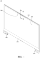
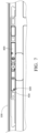
- FIG. 1 is a perspective view of a display device 10 according to a first embodiment of the disclosure.
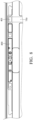
- FIG. 2 is an exploded view of the display device 10 in FIG. 1 .
- the display device 10 may, but not limited to, be a part or an entirety of an electronic product that can display images, such as a laptop computer.
- the display device 10 is, for example, a part of a laptop computer (not shown).
- the display device 10 may be a display of the laptop computer, and may be correspondingly connected to a host (not shown).
- the display device 10 includes a housing 100, a display panel 200, a flexible frame 300, a capturing assembly 400, a first positioning structure 500, a second positioning structure 600 and two reinforcement components 700.
- the housing 100 is made of, for example, aluminum.
- the housing 100 is manufactured by a processing method such as Computer Numerical Control (CNC).
- CNC Computer Numerical Control
- the housing 100 may be referred as a rear cover or the so-called "A cover or A shell”.
- the housing 100 has an accommodation space 101.
- the display panel 200 is located in the accommodation space 101.
- the display device 10 may further include a front cover 150 and two hinges 160.
- the front cover 150 is attached to a bottom edge of the display panel 200, and may be referred as the so-called "B cover or B shell".
- the front cover 150 is made of, for example, Mylar.
- the two hinges 160 are disposed on two opposite sides of the housing 100, respectively.
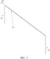
- FIG. 3 is a perspective view of the flexible frame 300 of the display device 10 in FIG. 2 from another viewing angle.
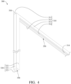
- FIG. 4 is a partially enlarged view of the flexible frame 300 in FIG. 3 .
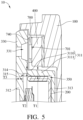
- FIG. 5 is a partially enlarged cross-sectional view of the display device 10 taken along line 5-5 in FIG. 1 .
- the flexible frame 300 is, for example, a sealing strip made of a flexible material such as rubber or silicone.
- the flexible frame 300 is attached to the housing 100 via, for example, an adhesive.
- the flexible frame 300 includes a first fitting body 310, two second fitting bodies 320 and a covering body 330.
- the first fitting body 310 and the two second fitting bodies 320 are approximately together in an inverted U-shape, and together form an installation space 350.
- the display panel 200 is located in the installation space 350.
- the display panel 200 is attached to the flexible frame 300 via, for example, an adhesive.
- the first fitting body 310 and the second fitting bodies 320 fit an upper edge and two side edges of the display panel 200, respectively. Therefore, the front cover 150, the first fitting body 310 and the second fitting bodies 320 together cover a periphery of the display panel 200.
- the display device 10 since the first fitting body 310 and the second fitting bodies 320 cover and fit the display panel 200, the display device 10 has a visual appearance similar to that of display devices adopting a thin bezel design.
- the first fitting body 310 includes a connecting part 311, a first clamping part 312, a second clamping part 313 and a plurality of ribs 314, and the first fitting body 310 has a recess 315.
- the connecting part 311 includes a narrower portion 3110 and a wider portion 3111 connected to each other.
- the narrower portion 3110 and the wider portion 3111 are connected to the first clamping part 312 and the second clamping part 313, respectively. That is, the first clamping part 312 and the second clamping part 313 are connected to two opposite ends of the connecting part 311, respectively.
- the connecting part 311, the first clamping part 312 and the second clamping part 313 are approximately together in, for example, an inverted U-shape.
- a thickness T1 of the narrower portion 3110 is smaller than a thickness T2 of the wider portion 3111.
- the recess 315 is located on a position where the narrower portion 3110 and the first clamping part 312 are connected.
- the ribs 314 are disposed in the recess 315.
- different sides of each rib 314 respectively are connected to the connecting part 311 and the first clamping part 312, so as to improve the structural strength of the first fitting body 310.
- the first fitting body may not include the ribs.
- the thickness T1 of the narrower portion 3110 is, for example, 1/3 to 1/2 of the thickness T3 of the first clamping part 312. In this embodiment, the thickness T1 is, for example, 1/2 of the thickness T3.
- the second fitting body 320 includes a connecting part 321, a first clamping part 322 and a second clamping part 323.
- the first clamping part 322 and the second clamping part 323 are connected to two opposite ends of the connecting part 321, respectively.
- the connecting part 321, the first clamping part 322 and the second clamping part 323 are together in approximately, for example, an inverted U-shape.
- the first clamping part 322 and the second clamping part 323 are connected to an end of each of the first clamping part 312 and the second clamping part 313 of the first fitting body 310.
- the covering body 330 has a plurality of exposing holes 331.
- the covering body 330 protrudes from a side of the connecting part 311 away from the installation space 350. That is, the covering body 330 protrudes outwards to widen a top part of the flexible frame 300.
- the widened top part of the flexible frame 300 will be prevented from being deformed due to the pressure if a user holds the display device 10 at a position adjacent to the top part of the flexible frame 300. In this way, the reliability for the flexible frame 300 to separate the display device 10 and the host (not shown) is improved, and the direct friction between the display device 10 and the host is prevented.
- the connecting part 311 includes the narrower portion 3110 connected to the first clamping part 312, a recess is prevented from being formed on a side of the first clamping part 312 or a side of the covering body 330 that is located away from the narrower portion 3110 (i.e., the side of the first clamping part 312 or the side of the covering body 330 that is located away from the narrower portion 3110 is prevented from being shrunk).
- a recess is prevented from being formed on the side of the first clamping part 312 or the side of the covering body 330 that is located away from the narrower portion 3110 (i.e., the side of the first clamping part 312 or the side of the covering body 330 that is located away from the narrower portion 3110 is prevented from being shrunk).
- the narrower portion 3110 and the first clamping part 312 it is further ensured that a recess is prevented from being formed on the side of the first clamping part 312 or the side of the covering body 330 that is located away from the narrower portion 3110 (i.e., it is further ensured that the side of the first clamping part 312 or the side of the covering body 330 that is located away from the narrower portion 3110 is prevented from being shrunk).
- the recess 315 is designed to be located on a position where the narrower portion 3110 and the first clamping part 312 are connected.
- the disclosure is not limited thereto. In other embodiments, the recess may be located on a position where the narrower portion and the covering body are connected.
- FIG. 6 is a partially enlarged exploded view of the display device 10 in FIG. 1 .
- the capturing assembly 400 is disposed on the housing 100.
- the flexible frame 300 is disposed on the housing 100.
- the connecting part 311 and the covering body 330 cover, for example, two adjacent sides of the capturing assembly 400, respectively.
- the housing 100 covers other two sides of the capturing assembly 400. Accordingly, the housing 100 and the flexible frame 300 together surround the capturing assembly 400.
- the disclosure is not limited thereto.
- the housing may merely cover one side of the capturing assembly, and the flexible frame may cover three adjacent sides of the capturing assembly. That is, in other embodiments, the capturing assembly may be disposed on the flexible frame.
- the connecting part 311 and the covering body 330 are not limited to covering two adjacent sides of the capturing assembly 400, respectively. In other embodiments, the connecting part and the covering body may cover two different sides of the capturing assembly that is not adjacent to each other.
- first fitting body 310, the two second fitting bodies 320 and the covering body 330 are, for example, integrally formed as a single piece by injection molding.
- first fitting body 310, the two second fitting bodies 320 and the covering body 330 have the same appearance.
- the display panel 200 and the capturing assembly 400 are respectively covered by the first fitting body 310, the two second fitting bodies 320 and the covering body 330 having the same appearance, which allows the display device 10 to have a uniform appearance.
- the covering body 330 of the flexible frame 300 rather than the housing 100 that covers the capturing assembly 400.
- the structural complexity of the housing 100 is reduced, thereby facilitating the manufacture of the housing 100 by the processing method such as CNC.
- the first positioning structure 500 is located on the housing 100.
- the second positioning structure 600 is located on the capturing assembly 400.
- the first positioning structure 500 and the second positioning structure 600 are a positioning protrusion and a positioning hole fitting each other, and are positioned with each other.
- the first positioning structure 500 is, for example, a positioning protrusion
- the second positioning structure 600 is, for example, a positioning hole.
- the capturing assembly 400 is mounted on the housing 100 via the first positioning structure 500 and the second positioning structure 600.
- the disclosure is not limited thereto.
- the first positioning structure may be located on the covering body of the flexible frame. That is, in other embodiments, the capturing assembly may be mounted on the flexible frame via the first positioning structure and the second positioning structure.
- the positions of the first positioning structure and the second positioning structure may be adjusted so as to allow the flexible frame to be shared among display devices of different specifications.
- the two reinforcement components 700 are attached to a side of the capturing assembly 400 that is located closer to the covering body 330 via, for example, an adhesive.
- the two reinforcement components 700 each have a plurality of exposing holes 701.
- the exposing holes 701 are connected to the exposing holes 331, respectively.
- a hardness of the reinforcement components 700 is, for example, higher than a hardness of the covering body 330.
- the covering body 330 is allowed to have a flat appearance when being assembled to the capturing assembly 400. Specifically, when the covering body 330 is pressed, the reinforcement components 700 that are harder support the covering body 330 so that the flat appearance of the covering body 330 can be maintained.
- the reinforcement components 700 prevent a connector 401 of the capturing assembly 400 from being detached from a circuit board (not labeled) of the capturing assembly 400.
- the display device 10 may further include a plurality of assembling components 740 that are, for example, double-sided tapes.
- the assembling components 740 are located between the covering body 330 and the reinforcement components 700. Also, the assembling components 740 do not cover the exposing holes 331 and 701.
- the display device may merely include one assembling component or may not include the assembling component.
- the assembling component may be a pad that is not adhesive.
- the exposing holes 331 and 701 expose the capturing assembly 400.
- the capturing assembly 400 includes a camera, and is, for example, a Charge-coupled Device (CCD) assembly.
- the capturing assembly 400 may further include one or more of an infrared sensor, a millimeter wave sensor, a microphone, and an eye tracker, and thus may have multiple functions, such as face recognition, sound recording and eye tracking.
- the capturing assembly 400 is able to receive different types of signals, such as light and sound, from the outside via the exposing holes 331 and 701.
- the flexible frame 300 since the flexible frame 300 includes the covering body 330 protruding outwards and covering the capturing assembly 400, the capturing assembly 400 is allowed to be moved from a side of the housing 100 that is located closer to the hinge 160 to a position adjacent to the covering body 330 of the flexible frame 300 that is in the form of a thin bezel. Accordingly, the capturing assembly 400 is disposed on a top part of the display device so as to prevent the range for the capturing assembly 400 to capture signals from being reduced. In this way, the flexible frame 300 allows the display device 10 to adopt a thin bezel design while preventing the range for the capturing assembly 400 to capture signals from being reduced.
- each of the covering body and the reinforcement component may merely have one exposing hole.
- the capturing assembly 400 is not limited to including the camera. In other embodiments where the capturing assembly is not demanded to capture images, the capturing assembly may not include the camera.
- FIGS. 7 to 17 showing an assembling method of the display device 10 in FIG. 1 .
- the assembling method of the display device 10 according to the first embodiment may include following steps.
- the housing 100 and the capturing assembly 400 are provided, and the first positioning structure 500 and the second positioning structure 600 are positioned with each other.
- a wiring 750 is electrically connected to the connector 401 of the capturing assembly 400.
- the two reinforcement components 700 are attached to a side of the housing 100 and a side of the capturing assembly 400 via adhering.
- a display panel 200 is provided, and a plurality of adhesives 20 are attached on a rear surface 201 of the display panel 200.
- release papers (not shown) of the adhesives 20 are removed, and the display panel 200 is assembled to the flexible frame 300 via the adhesives 20.
- a plurality of adhesives 21 are attached to the flexible frame 300.
- a wiring 760 is electrically connected to a connector 202 of the display panel 200.
- the display panel 200 and the flexible frame 300 are assembled to the housing 100, such that a front surface 203 of the display panel 200 facing away from the rear surface 201 is exposed to the outside.
- release papers (not shown) of the adhesives 21 attached to the first fitting body 310 are removed, and the first fitting body 310 and the covering body 330 are assembled into the housing 100.
- release papers (not shown) of the adhesives 21 attached to the second fitting body 320 are removed, and the two second fitting bodies 320 are assembled into the housing 100.
- any unnecessary gap between the first fitting body 310 and the housing 100 or that between the covering body 330 and the housing 100 is prevented to maintain the flat appearance of the flexible frame 300.
- the flexible frame 300 before being attached to the housing 100, the flexible frame 300 is assembled to and thus supported by the display panel 200. Thus, original assembling processes are maintained so as to reduce the manufacturing costs of the display device 10.
- the two hinges 160 are fixed to the housing 100 via, for example, screwing.
- two hinge covers 170 are disposed on the housing 100 to respectively cover at least part of the two hinges 160.
- the front cover 150 is attached to a bottom edge of the display panel 200.
- the assembly of the display device 10 is completed so far.
- the reinforcement components are disposed outside the covering body for the convenience of the assembly, but the disclosure is not limited to the relationship between the reinforcement components and the covering body.
- FIG. 18 is an exploded view of a display device 10a according to a second embodiment of the disclosure.
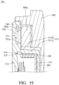
- FIG. 19 is a partially enlarged cross-sectional view of the display device 10a in FIG. 18 .
- the display device 10a of this embodiment and the display device 10 of the first embodiment will be described.
- the reinforcement components 700a are embedded in the covering body 330.
- the reinforcement components 700a and the flexible frame 300 are together formed by over molding or double injection molding.
- Exposing holes 701a of the reinforcement components 700a are located in the exposing holes 331 of the covering body 330.
- the assembling components 740 are located between the covering body 330 and a capturing assembly 400a.
- the flexible frame since the flexible frame includes the covering body protruding outwards and covering the capturing assembly, the capturing assembly is allowed to be moved from a side of the housing that is located closer to the hinge to the position adjacent to the covering body of the flexible frame that is in the form of a thin bezel. Accordingly, the capturing assembly is allowed to be disposed on the top part of the display device to prevent the range for the capturing assembly to capture signals from being reduced. In this way, the flexible frame allows the display device to adopt a thin bezel design while preventing the range for the capturing assembly to capture signals from being reduced.
Landscapes
- Engineering & Computer Science (AREA)
- Computer Hardware Design (AREA)
- Theoretical Computer Science (AREA)
- Physics & Mathematics (AREA)
- General Engineering & Computer Science (AREA)
- General Physics & Mathematics (AREA)
- Human Computer Interaction (AREA)
- Nonlinear Science (AREA)
- Mathematical Physics (AREA)
- Chemical & Material Sciences (AREA)
- Crystallography & Structural Chemistry (AREA)
- Optics & Photonics (AREA)
- Devices For Indicating Variable Information By Combining Individual Elements (AREA)
- Casings For Electric Apparatus (AREA)
- Liquid Crystal (AREA)
Abstract
A display device (10, 10a) and a flexible frame (300). The display device includes a housing (100), a display panel (200), a flexible frame and a capturing assembly (400, 400a). The flexible frame includes a first fitting body (310), two second fitting bodies (320) and a covering body (330). The two second fitting bodies are connected to two opposite ends of the first fitting body, respectively. The first fitting body and the two second fitting bodies together from an installation space (350), and the display panel is located in the installation space. The covering body protrudes from a side of the first fitting body that is located away from the installation space and has at least one exposing hole (331). The capturing assembly is disposed on the housing. The first fitting body and the covering body cover different sides of the capturing assembly, respectively. The exposing hole exposes the capturing assembly.
Description
- The disclosure relates to an electronic device and a flexible frame, more particularly to a display device and a flexible frame fitting a display panel.
- Laptop computers have become one of the electronic products that are widely used due to their portability. Recently, the display of the laptop computer usually features a thin bezel design, so as to be thin and lightweight while having increased screen-to-body (STB) ratio and improved visual appeal. To further slim down the display bezel, some manufactures have relocated the camera to the bottom side of the display closer to the hinge.
- However, placing the camera on the side of the display closer to the hinge limits the capture range and angle of the camera. In this way, the camera may be unable to capture desired images. Due to the above reasons, it is difficult for conventional laptop computers to adopt thin bezels without reducing the range and angle for the camera to capture images.
- The disclosure provides a display device and a flexible frame that enable the display device to adopt a thin bezel design while preventing the range for the capturing assembly to capture signals from being reduced.
- One embodiment of this disclosure provides a display device including a housing, a display panel, a flexible frame and a covering body. The housing has an accommodation space. The display panel is located in the accommodation space. The flexible frame includes a first fitting body, two second fitting bodies and a covering body. The two second fitting bodies are connected to two opposite ends of the first fitting body, respectively. The first fitting body and the two second fitting bodies together from an installation space, and the display panel is located in the installation space. The covering body protrudes from a side of the first fitting body that is located away from the installation space and has at least one exposing hole. The capturing assembly is disposed on the housing. The first fitting body and the covering body cover different sides of the capturing assembly, respectively. The at least one exposing hole exposes the capturing assembly.
- Another embodiment of this disclosure provides a flexible frame including a first fitting body, two second fitting bodies and a covering body. The two second fitting bodies are connected to two opposite ends of the first fitting body, respectively. The first fitting body and the two second fitting bodies together form an installation space. The covering body protrudes from a side of the first fitting body that is located away from the installation space and has at least one exposing hole.
- According to the display device and the flexible frame disclosed by above embodiments, since the flexible frame includes the covering body protruding outwards and covering the capturing assembly, the capturing assembly is allowed to be moved from a side of the housing that is located closer to the hinge to the position adjacent to the covering body of the flexible frame that is in the form of a thin bezel. Accordingly, the capturing assembly is allowed to be disposed on the top part of the display device to prevent the range for the capturing assembly to capture signals from being reduced. In this way, the flexible frame allows the display device to adopt a thin bezel design while preventing the range for the capturing assembly to capture signals from being reduced.
- The present disclosure will become better understood from the detailed description given herein below and the accompanying drawings which are given by way of illustration only and thus are not intending to limit the present disclosure and wherein:
-
FIG. 1 is a perspective view of a display device according to a first embodiment of the disclosure; -
FIG. 2 is an exploded view of the display device inFIG. 1 ; -
FIG. 3 is a perspective view of a flexible frame of the display device inFIG. 2 from another viewing angle; -
FIG. 4 is a partially enlarged view of the flexible frame inFIG. 3 ; -
FIG. 5 is a partially enlarged cross-sectional view of the display device taken along line 5-5 inFIG. 1 ; -
FIG. 6 is a partially enlarged exploded view of the display device inFIG. 1 ; -
FIGS. 7-17 show an assembling method of the display device inFIG. 1 ; -
FIG. 18 is an exploded view of a display device according to a second embodiment of the disclosure; and -
FIG. 19 is a partially enlarged cross-sectional view of the display device inFIG. 18 . - In the following detailed description, for purposes of explanation, numerous specific details are set forth in order to provide a thorough understanding of the disclosed embodiments. It will be apparent, however, that one or more embodiments may be practiced without these specific details. In other instances, well-known structures and devices are schematically shown in order to simplify the drawing.
- Please refer to
FIGS. 1 to 2 .FIG. 1 is a perspective view of adisplay device 10 according to a first embodiment of the disclosure.FIG. 2 is an exploded view of thedisplay device 10 inFIG. 1 . - The
display device 10 may, but not limited to, be a part or an entirety of an electronic product that can display images, such as a laptop computer. In this embodiment, to explain the spirit of the disclosure, thedisplay device 10 is, for example, a part of a laptop computer (not shown). In such embodiment, thedisplay device 10 may be a display of the laptop computer, and may be correspondingly connected to a host (not shown). In this embodiment, thedisplay device 10 includes ahousing 100, adisplay panel 200, aflexible frame 300, a capturingassembly 400, afirst positioning structure 500, asecond positioning structure 600 and tworeinforcement components 700. - The
housing 100 is made of, for example, aluminum. Thehousing 100 is manufactured by a processing method such as Computer Numerical Control (CNC). Thehousing 100 may be referred as a rear cover or the so-called "A cover or A shell". In addition, thehousing 100 has anaccommodation space 101. Thedisplay panel 200 is located in theaccommodation space 101. In this embodiment, thedisplay device 10 may further include afront cover 150 and twohinges 160. Thefront cover 150 is attached to a bottom edge of thedisplay panel 200, and may be referred as the so-called "B cover or B shell". Moreover, thefront cover 150 is made of, for example, Mylar. The twohinges 160 are disposed on two opposite sides of thehousing 100, respectively. - Please refer to
FIGS. 3 to 5 .FIG. 3 is a perspective view of theflexible frame 300 of thedisplay device 10 inFIG. 2 from another viewing angle.FIG. 4 is a partially enlarged view of theflexible frame 300 inFIG. 3 .FIG. 5 is a partially enlarged cross-sectional view of thedisplay device 10 taken along line 5-5 inFIG. 1 . Theflexible frame 300 is, for example, a sealing strip made of a flexible material such as rubber or silicone. Theflexible frame 300 is attached to thehousing 100 via, for example, an adhesive. Theflexible frame 300 includes a firstfitting body 310, two secondfitting bodies 320 and acovering body 330. The firstfitting body 310 and the two secondfitting bodies 320 are approximately together in an inverted U-shape, and together form aninstallation space 350. Thedisplay panel 200 is located in theinstallation space 350. In addition, thedisplay panel 200 is attached to theflexible frame 300 via, for example, an adhesive. The firstfitting body 310 and the secondfitting bodies 320 fit an upper edge and two side edges of thedisplay panel 200, respectively. Therefore, thefront cover 150, the firstfitting body 310 and the secondfitting bodies 320 together cover a periphery of thedisplay panel 200. Further, since the firstfitting body 310 and the secondfitting bodies 320 cover and fit thedisplay panel 200, thedisplay device 10 has a visual appearance similar to that of display devices adopting a thin bezel design. - In this embodiment, the first
fitting body 310 includes a connectingpart 311, afirst clamping part 312, asecond clamping part 313 and a plurality ofribs 314, and the firstfitting body 310 has arecess 315. - As shown in
FIG. 5 , the connectingpart 311 includes anarrower portion 3110 and awider portion 3111 connected to each other. Thenarrower portion 3110 and thewider portion 3111 are connected to thefirst clamping part 312 and thesecond clamping part 313, respectively. That is, thefirst clamping part 312 and thesecond clamping part 313 are connected to two opposite ends of the connectingpart 311, respectively. Also, the connectingpart 311, thefirst clamping part 312 and thesecond clamping part 313 are approximately together in, for example, an inverted U-shape. A thickness T1 of thenarrower portion 3110 is smaller than a thickness T2 of thewider portion 3111. Therecess 315 is located on a position where thenarrower portion 3110 and thefirst clamping part 312 are connected. Theribs 314 are disposed in therecess 315. In detail, different sides of eachrib 314 respectively are connected to the connectingpart 311 and thefirst clamping part 312, so as to improve the structural strength of the firstfitting body 310. In other embodiments where the demand for the structural strength of the first fitting body is lower, the first fitting body may not include the ribs. - In addition, the thickness T1 of the
narrower portion 3110 is, for example, 1/3 to 1/2 of the thickness T3 of thefirst clamping part 312. In this embodiment, the thickness T1 is, for example, 1/2 of the thickness T3. - Since the two second
fitting bodies 320 are similar in structure, the detail structure of only one of them will be described below. The secondfitting body 320 includes a connectingpart 321, afirst clamping part 322 and asecond clamping part 323. Thefirst clamping part 322 and thesecond clamping part 323 are connected to two opposite ends of the connectingpart 321, respectively. The connectingpart 321, thefirst clamping part 322 and thesecond clamping part 323 are together in approximately, for example, an inverted U-shape. Thefirst clamping part 322 and thesecond clamping part 323 are connected to an end of each of thefirst clamping part 312 and thesecond clamping part 313 of the firstfitting body 310. - The covering
body 330 has a plurality of exposingholes 331. In addition, the coveringbody 330 protrudes from a side of the connectingpart 311 away from theinstallation space 350. That is, the coveringbody 330 protrudes outwards to widen a top part of theflexible frame 300. Thus, when the laptop computer including thedisplay device 10 of this embodiment is closed, the widened top part of theflexible frame 300 will be prevented from being deformed due to the pressure if a user holds thedisplay device 10 at a position adjacent to the top part of theflexible frame 300. In this way, the reliability for theflexible frame 300 to separate thedisplay device 10 and the host (not shown) is improved, and the direct friction between thedisplay device 10 and the host is prevented. - Note that since the connecting
part 311 includes thenarrower portion 3110 connected to thefirst clamping part 312, a recess is prevented from being formed on a side of thefirst clamping part 312 or a side of the coveringbody 330 that is located away from the narrower portion 3110 (i.e., the side of thefirst clamping part 312 or the side of the coveringbody 330 that is located away from thenarrower portion 3110 is prevented from being shrunk). In other words, due to therecess 315 formed on a position where thenarrower portion 3110 and thefirst clamping part 312 are connected, a recess is prevented from being formed on the side of thefirst clamping part 312 or the side of the coveringbody 330 that is located away from the narrower portion 3110 (i.e., the side of thefirst clamping part 312 or the side of the coveringbody 330 that is located away from thenarrower portion 3110 is prevented from being shrunk). In addition, due to the thickness relationship between thenarrower portion 3110 and thefirst clamping part 312, it is further ensured that a recess is prevented from being formed on the side of thefirst clamping part 312 or the side of the coveringbody 330 that is located away from the narrower portion 3110 (i.e., it is further ensured that the side of thefirst clamping part 312 or the side of the coveringbody 330 that is located away from thenarrower portion 3110 is prevented from being shrunk). - Furthermore, in this embodiment, in order to facilitate the demolding during the manufacture of the
flexible frame 300, therecess 315 is designed to be located on a position where thenarrower portion 3110 and thefirst clamping part 312 are connected. However, the disclosure is not limited thereto. In other embodiments, the recess may be located on a position where the narrower portion and the covering body are connected. - Please refer to
FIGS. 5 and6. FIG. 6 is a partially enlarged exploded view of thedisplay device 10 inFIG. 1 . The capturingassembly 400 is disposed on thehousing 100. Also, theflexible frame 300 is disposed on thehousing 100. In detail, the connectingpart 311 and the coveringbody 330 cover, for example, two adjacent sides of the capturingassembly 400, respectively. In addition, thehousing 100 covers other two sides of the capturingassembly 400. Accordingly, thehousing 100 and theflexible frame 300 together surround the capturingassembly 400. However, the disclosure is not limited thereto. In other embodiments, the housing may merely cover one side of the capturing assembly, and the flexible frame may cover three adjacent sides of the capturing assembly. That is, in other embodiments, the capturing assembly may be disposed on the flexible frame. - Moreover, the connecting
part 311 and the coveringbody 330 are not limited to covering two adjacent sides of the capturingassembly 400, respectively. In other embodiments, the connecting part and the covering body may cover two different sides of the capturing assembly that is not adjacent to each other. - Additionally, the first
fitting body 310, the two secondfitting bodies 320 and the coveringbody 330 are, for example, integrally formed as a single piece by injection molding. Thus, the firstfitting body 310, the two secondfitting bodies 320 and the coveringbody 330 have the same appearance. In this way, thedisplay panel 200 and the capturingassembly 400 are respectively covered by the firstfitting body 310, the two secondfitting bodies 320 and the coveringbody 330 having the same appearance, which allows thedisplay device 10 to have a uniform appearance. - Further, in this embodiment, it is the covering
body 330 of theflexible frame 300 rather than thehousing 100 that covers the capturingassembly 400. Thus, the structural complexity of thehousing 100 is reduced, thereby facilitating the manufacture of thehousing 100 by the processing method such as CNC. - The
first positioning structure 500 is located on thehousing 100. Thesecond positioning structure 600 is located on the capturingassembly 400. Thefirst positioning structure 500 and thesecond positioning structure 600 are a positioning protrusion and a positioning hole fitting each other, and are positioned with each other. In this embodiment, thefirst positioning structure 500 is, for example, a positioning protrusion, and thesecond positioning structure 600 is, for example, a positioning hole. - Note that in this embodiment, the capturing
assembly 400 is mounted on thehousing 100 via thefirst positioning structure 500 and thesecond positioning structure 600. However, the disclosure is not limited thereto. In other embodiments, the first positioning structure may be located on the covering body of the flexible frame. That is, in other embodiments, the capturing assembly may be mounted on the flexible frame via the first positioning structure and the second positioning structure. - In other embodiments, if the specification of the display device is changed so that the configurations of the capturing assembly and the display panel included in the display device are changed, the positions of the first positioning structure and the second positioning structure may be adjusted so as to allow the flexible frame to be shared among display devices of different specifications.
- The two
reinforcement components 700 are attached to a side of the capturingassembly 400 that is located closer to thecovering body 330 via, for example, an adhesive. In addition, the tworeinforcement components 700 each have a plurality of exposingholes 701. The exposingholes 701 are connected to the exposingholes 331, respectively. A hardness of thereinforcement components 700 is, for example, higher than a hardness of the coveringbody 330. With the tworeinforcement components 700, the coveringbody 330 is allowed to have a flat appearance when being assembled to the capturingassembly 400. Specifically, when the coveringbody 330 is pressed, thereinforcement components 700 that are harder support the coveringbody 330 so that the flat appearance of the coveringbody 330 can be maintained. In addition, thereinforcement components 700 prevent aconnector 401 of the capturingassembly 400 from being detached from a circuit board (not labeled) of the capturingassembly 400. - As shown in
FIG. 5 , in this embodiment, thedisplay device 10 may further include a plurality of assemblingcomponents 740 that are, for example, double-sided tapes. The assemblingcomponents 740 are located between the coveringbody 330 and thereinforcement components 700. Also, the assemblingcomponents 740 do not cover the exposingholes - In addition, the exposing
holes assembly 400. In this embodiment, the capturingassembly 400 includes a camera, and is, for example, a Charge-coupled Device (CCD) assembly. In addition, the capturingassembly 400 may further include one or more of an infrared sensor, a millimeter wave sensor, a microphone, and an eye tracker, and thus may have multiple functions, such as face recognition, sound recording and eye tracking. The capturingassembly 400 is able to receive different types of signals, such as light and sound, from the outside via the exposingholes flexible frame 300 includes the coveringbody 330 protruding outwards and covering the capturingassembly 400, the capturingassembly 400 is allowed to be moved from a side of thehousing 100 that is located closer to thehinge 160 to a position adjacent to thecovering body 330 of theflexible frame 300 that is in the form of a thin bezel. Accordingly, the capturingassembly 400 is disposed on a top part of the display device so as to prevent the range for the capturingassembly 400 to capture signals from being reduced. In this way, theflexible frame 300 allows thedisplay device 10 to adopt a thin bezel design while preventing the range for the capturingassembly 400 to capture signals from being reduced. - In other embodiments, each of the covering body and the reinforcement component may merely have one exposing hole. In addition, in other embodiments, there may merely be one reinforcement component.
- Note that the capturing
assembly 400 is not limited to including the camera. In other embodiments where the capturing assembly is not demanded to capture images, the capturing assembly may not include the camera. - Please refer to
FIGS. 7 to 17 showing an assembling method of thedisplay device 10 inFIG. 1 . The assembling method of thedisplay device 10 according to the first embodiment may include following steps. - As shown in
FIG. 7 , thehousing 100 and the capturingassembly 400 are provided, and thefirst positioning structure 500 and thesecond positioning structure 600 are positioned with each other. - As shown in
FIG. 8 , awiring 750 is electrically connected to theconnector 401 of the capturingassembly 400. - As shown in
FIG. 9 , the tworeinforcement components 700 are attached to a side of thehousing 100 and a side of the capturingassembly 400 via adhering. - As shown in
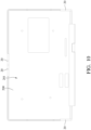
FIG. 10 , adisplay panel 200 is provided, and a plurality ofadhesives 20 are attached on arear surface 201 of thedisplay panel 200. - As shown in
FIGS. 10 and11 , release papers (not shown) of theadhesives 20 are removed, and thedisplay panel 200 is assembled to theflexible frame 300 via theadhesives 20. - As shown in
FIG. 12 , a plurality ofadhesives 21 are attached to theflexible frame 300. - As shown in
FIG. 13 , awiring 760 is electrically connected to aconnector 202 of thedisplay panel 200. - As shown in
FIGS. 12 and14 , thedisplay panel 200 and theflexible frame 300 are assembled to thehousing 100, such that afront surface 203 of thedisplay panel 200 facing away from therear surface 201 is exposed to the outside. In detail, firstly, release papers (not shown) of theadhesives 21 attached to the firstfitting body 310 are removed, and the firstfitting body 310 and the coveringbody 330 are assembled into thehousing 100. Then, release papers (not shown) of theadhesives 21 attached to the secondfitting body 320 are removed, and the two secondfitting bodies 320 are assembled into thehousing 100. In this way, any unnecessary gap between the firstfitting body 310 and thehousing 100 or that between the coveringbody 330 and thehousing 100 is prevented to maintain the flat appearance of theflexible frame 300. In this embodiment, before being attached to thehousing 100, theflexible frame 300 is assembled to and thus supported by thedisplay panel 200. Thus, original assembling processes are maintained so as to reduce the manufacturing costs of thedisplay device 10. - As shown in
FIG. 15 , the two hinges 160 are fixed to thehousing 100 via, for example, screwing. - As shown in
FIG. 16 , two hinge covers 170 are disposed on thehousing 100 to respectively cover at least part of the two hinges 160. - As shown in
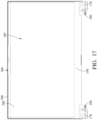
FIG. 17 , thefront cover 150 is attached to a bottom edge of thedisplay panel 200. The assembly of thedisplay device 10 is completed so far. - In the first embodiment, the reinforcement components are disposed outside the covering body for the convenience of the assembly, but the disclosure is not limited to the relationship between the reinforcement components and the covering body.
- Other embodiments are described below for illustrative purposes. It is to be noted that the following embodiments use the reference numerals and a part of the contents of the above embodiments, the same reference numerals are used to denote the same or similar elements, and the description of the same technical contents is omitted. For the description of the omitted part, reference may be made to the above embodiments, and details are not described in the following embodiments.
- Please refer to
FIGS. 18 and19 .FIG. 18 is an exploded view of adisplay device 10a according to a second embodiment of the disclosure.FIG. 19 is a partially enlarged cross-sectional view of thedisplay device 10a inFIG. 18 . Hereinafter, only the difference between thedisplay device 10a of this embodiment and thedisplay device 10 of the first embodiment will be described. - In this embodiment, the
reinforcement components 700a are embedded in thecovering body 330. For example, thereinforcement components 700a and theflexible frame 300 are together formed by over molding or double injection molding. Exposing holes 701a of thereinforcement components 700a are located in the exposingholes 331 of the coveringbody 330. The assemblingcomponents 740 are located between the coveringbody 330 and a capturingassembly 400a. - According to the display device and the flexible frame disclosed by above embodiments, since the flexible frame includes the covering body protruding outwards and covering the capturing assembly, the capturing assembly is allowed to be moved from a side of the housing that is located closer to the hinge to the position adjacent to the covering body of the flexible frame that is in the form of a thin bezel. Accordingly, the capturing assembly is allowed to be disposed on the top part of the display device to prevent the range for the capturing assembly to capture signals from being reduced. In this way, the flexible frame allows the display device to adopt a thin bezel design while preventing the range for the capturing assembly to capture signals from being reduced.
- It will be apparent to those skilled in the art that various modifications and variations can be made to the present disclosure. It is intended that the specification and examples be considered as exemplary embodiments only, with a scope of the disclosure being indicated by the following claims and their equivalents.
Claims (10)
- A display device (10, 10a), comprising:a housing (100), having an accommodation space (101);a display panel (200), located in the accommodation space;a flexible frame (300), comprising:a first fitting body (310);two second fitting bodies (320), connected to two opposite ends of the first fitting body, respectively, wherein the first fitting body and the two second fitting bodies together from an installation space (350), and the display panel is located in the installation space; anda covering body (330), protruding from a side of the first fitting body that is located away from the installation space and having at least one exposing hole (331); anda capturing assembly (400, 400a), disposed on the housing, wherein the first fitting body and the covering body cover different sides of the capturing assembly, respectively, and the at least one exposing hole exposes the capturing assembly.
- The display device according to claim 1, wherein the first fitting body comprises a connecting part (311), a first clamping part (312) and a second clamping part (313), the first clamping part and the second clamping part are connected to two opposite ends of the connecting part, respectively, two opposite ends of the first clamping part are connected to the two second fitting bodies, respectively, two opposite ends of the second clamping part are connected to the two second fitting bodies, respectively, the covering body protrudes from a side of the connecting part that is located away from the installation space, the connecting part and the covering body cover different sides of the capturing assembly, respectively, the first fitting body has a recess (315), and the recess is located on a position where the connecting part and the first clamping part are connected.
- The display device according to claim 2, wherein the first fitting body further comprises a plurality of ribs (314) located in the recess.
- The display device according to claim 2, wherein the connecting part and the covering body cover two adjacent sides of the capturing assembly, respectively.
- The display device according to claim 2, wherein the connecting part comprises a narrower portion (3110) and a wider portion (3111) that are connected to each other, the narrower portion and the wider portion are connected to the first clamping part and the second clamping part, respectively, the recess is located on a position where the narrower portion and the first clamping part are connected, a thickness (T1) of the narrower portion is smaller than a thickness of the wider portion (T2), and the thickness of the narrower portion is 1/3 to 1/2 of a thickness (T3) of the first clamping part.
- The display device according to claim 1, further comprising a first positioning structure (500) and a second positioning structure (600), wherein the first positioning structure is located on the housing, the second positioning structure is located on the capturing assembly, and the first positioning structure and the second positioning structure respectively are a positioning protrusion and a positioning hole fitting with each other, and are positioned with each other.
- The display device according to claim 1, further comprising at least one reinforcement component (700), wherein the at least one reinforcement component is disposed on a side of the capturing assembly that is located closer to the covering body, and a hardness of the at least one reinforcement component is higher than a hardness of the covering body.
- The display device according to claim 1, further comprising at least one reinforcement component (700a), wherein the at least one reinforcement component is embedded in the covering body, and a hardness of the at least one reinforcement component is higher than a hardness of the covering body.
- The display device according to claim 1, wherein the capturing assembly comprises a camera.
- A flexible frame (300), comprising:a first fitting body (310);two second fitting bodies (320), connected to two opposite ends of the first fitting body, respectively, wherein the first fitting body and the two second fitting bodies together form an installation space (350); anda covering body (330), protruding from a side of the first fitting body that is located away from the installation space and having at least one exposing hole (331).
Applications Claiming Priority (1)
| Application Number | Priority Date | Filing Date | Title |
|---|---|---|---|
| TW112128396A TWI876447B (en) | 2023-07-28 | 2023-07-28 | Display device and flexible frame |
Publications (1)
| Publication Number | Publication Date |
|---|---|
| EP4498152A1 true EP4498152A1 (en) | 2025-01-29 |
Family
ID=91961976
Family Applications (1)
| Application Number | Title | Priority Date | Filing Date |
|---|---|---|---|
| EP24190006.7A Pending EP4498152A1 (en) | 2023-07-28 | 2024-07-22 | Display device and flexible frame |
Country Status (6)
| Country | Link |
|---|---|
| US (1) | US20250036165A1 (en) |
| EP (1) | EP4498152A1 (en) |
| JP (1) | JP7721750B2 (en) |
| KR (1) | KR20250018098A (en) |
| AU (1) | AU2024205019B2 (en) |
| TW (1) | TWI876447B (en) |
Citations (4)
| Publication number | Priority date | Publication date | Assignee | Title |
|---|---|---|---|---|
| EP3343275B1 (en) * | 2016-12-29 | 2019-06-19 | Giga-Byte Technology Co., Ltd. | Display device |
| CN209297645U (en) * | 2018-11-14 | 2019-08-23 | 技嘉科技股份有限公司 | display device |
| US20220163869A1 (en) * | 2020-11-26 | 2022-05-26 | Lenovo (Singapore) Pte. Ltd. | Information device and method of assembling the same |
| US20230064928A1 (en) * | 2021-08-31 | 2023-03-02 | Giga-Byte Technology Co., Ltd. | Display device and electronic system including the same |
Family Cites Families (13)
| Publication number | Priority date | Publication date | Assignee | Title |
|---|---|---|---|---|
| TW352206U (en) * | 1997-12-30 | 1999-02-01 | First Int Computer Inc | Structure for hidden type image picking apparatus of notebook computer |
| JP2013073009A (en) * | 2011-09-28 | 2013-04-22 | Sony Corp | Information processing apparatus |
| KR101406129B1 (en) * | 2012-03-28 | 2014-06-13 | 엘지디스플레이 주식회사 | Display apparatus |
| JP6667479B2 (en) * | 2017-07-27 | 2020-03-18 | レノボ・シンガポール・プライベート・リミテッド | Electronics |
| TWM574699U (en) * | 2018-11-14 | 2019-02-21 | 技嘉科技股份有限公司 | Display device |
| TWM581713U (en) * | 2019-01-02 | 2019-08-01 | 威強電工業電腦股份有限公司 | Electronic device with capability of covering an image capturing module |
| US20210034109A1 (en) * | 2019-08-02 | 2021-02-04 | Dell Products L.P. | Information handling system flexible display bezel |
| CN211959383U (en) * | 2020-04-29 | 2020-11-17 | 青岛海信商用显示股份有限公司 | Display device |
| JP7645736B2 (en) * | 2021-07-21 | 2025-03-14 | ニデックプレシジョン株式会社 | Blade drive device |
| CN115686245A (en) * | 2021-07-21 | 2023-02-03 | 广州视源电子科技股份有限公司 | Narrow-frame touch display device |
| CN118020039A (en) * | 2021-09-29 | 2024-05-10 | 松下知识产权经营株式会社 | Electronic equipment |
| CN217217224U (en) * | 2022-01-18 | 2022-08-16 | 广州视源电子科技股份有限公司 | Display device panel beating frame and display device |
| JP7366207B1 (en) * | 2022-08-03 | 2023-10-20 | レノボ・シンガポール・プライベート・リミテッド | Electronics |
-
2023
- 2023-07-28 TW TW112128396A patent/TWI876447B/en active
-
2024
- 2024-07-16 JP JP2024113445A patent/JP7721750B2/en active Active
- 2024-07-19 KR KR1020240095742A patent/KR20250018098A/en active Pending
- 2024-07-19 US US18/778,867 patent/US20250036165A1/en active Pending
- 2024-07-22 AU AU2024205019A patent/AU2024205019B2/en active Active
- 2024-07-22 EP EP24190006.7A patent/EP4498152A1/en active Pending
Patent Citations (4)
| Publication number | Priority date | Publication date | Assignee | Title |
|---|---|---|---|---|
| EP3343275B1 (en) * | 2016-12-29 | 2019-06-19 | Giga-Byte Technology Co., Ltd. | Display device |
| CN209297645U (en) * | 2018-11-14 | 2019-08-23 | 技嘉科技股份有限公司 | display device |
| US20220163869A1 (en) * | 2020-11-26 | 2022-05-26 | Lenovo (Singapore) Pte. Ltd. | Information device and method of assembling the same |
| US20230064928A1 (en) * | 2021-08-31 | 2023-03-02 | Giga-Byte Technology Co., Ltd. | Display device and electronic system including the same |
Also Published As
| Publication number | Publication date |
|---|---|
| TW202505279A (en) | 2025-02-01 |
| TWI876447B (en) | 2025-03-11 |
| AU2024205019A1 (en) | 2025-02-13 |
| AU2024205019B2 (en) | 2026-02-26 |
| KR20250018098A (en) | 2025-02-04 |
| JP7721750B2 (en) | 2025-08-12 |
| US20250036165A1 (en) | 2025-01-30 |
| JP2025020015A (en) | 2025-02-07 |
Similar Documents
| Publication | Publication Date | Title |
|---|---|---|
| US10171896B2 (en) | Electronic device with side speaker hole | |
| KR102013053B1 (en) | Screen assembly with a fingerprint module and electronic device | |
| US10860054B2 (en) | Electronic devices with cover layers mounted to displays | |
| US10554797B2 (en) | Mobile terminal, shell module, display module, and method of assembling display module | |
| US9098242B2 (en) | Electronic devices with cover layers mounted to displays | |
| EP3448056B1 (en) | Electronic device including electronic part and earphone jack assembly | |
| US11886219B2 (en) | Flexible display module and electronic device including the same | |
| US12530058B2 (en) | Mobile terminal | |
| US11490185B2 (en) | Electronic device | |
| US11402875B2 (en) | Electronic device including display | |
| US8238119B2 (en) | Electronic device | |
| US9088703B2 (en) | Window for preventing camera distortion in an electronic device | |
| CN113037894B (en) | Electronic equipment | |
| US20140036162A1 (en) | Television receiver and electronic device | |
| US10912219B2 (en) | Waterproof structure | |
| AU2024205019B2 (en) | Display device and flexible frame | |
| JP7307838B1 (en) | Electronics | |
| US20260096042A1 (en) | Electronic device comprising waterproof structure | |
| WO2021093428A1 (en) | Electronic terminal | |
| CN112700728A (en) | Display module and electronic equipment | |
| US12353080B1 (en) | Display device | |
| CN119440172A (en) | Display device and flexible frame |
Legal Events
| Date | Code | Title | Description |
|---|---|---|---|
| PUAI | Public reference made under article 153(3) epc to a published international application that has entered the european phase |
Free format text: ORIGINAL CODE: 0009012 |
|
| STAA | Information on the status of an ep patent application or granted ep patent |
Free format text: STATUS: THE APPLICATION HAS BEEN PUBLISHED |
|
| AK | Designated contracting states |
Kind code of ref document: A1 Designated state(s): AL AT BE BG CH CY CZ DE DK EE ES FI FR GB GR HR HU IE IS IT LI LT LU LV MC ME MK MT NL NO PL PT RO RS SE SI SK SM TR |
|
| STAA | Information on the status of an ep patent application or granted ep patent |
Free format text: STATUS: REQUEST FOR EXAMINATION WAS MADE |
|
| 17P | Request for examination filed |
Effective date: 20250702 |