EP4498101A1 - Flying drone for checking lightning equipment and associated method - Google Patents
Flying drone for checking lightning equipment and associated method Download PDFInfo
- Publication number
- EP4498101A1 EP4498101A1 EP23315293.3A EP23315293A EP4498101A1 EP 4498101 A1 EP4498101 A1 EP 4498101A1 EP 23315293 A EP23315293 A EP 23315293A EP 4498101 A1 EP4498101 A1 EP 4498101A1
- Authority
- EP
- European Patent Office
- Prior art keywords
- flying drone
- probe
- lightning
- drone
- femtosecond laser
- Prior art date
- Legal status (The legal status is an assumption and is not a legal conclusion. Google has not performed a legal analysis and makes no representation as to the accuracy of the status listed.)
- Withdrawn
Links
Images


Classifications
-
- G—PHYSICS
- G01—MEASURING; TESTING
- G01R—MEASURING ELECTRIC VARIABLES; MEASURING MAGNETIC VARIABLES
- G01R29/00—Arrangements for measuring or indicating electric quantities not covered by groups G01R19/00 - G01R27/00
- G01R29/08—Measuring electromagnetic field characteristics
- G01R29/0807—Measuring electromagnetic field characteristics characterised by the application
- G01R29/0814—Field measurements related to measuring influence on or from apparatus, components or humans, e.g. in ESD, EMI, EMC, EMP testing, measuring radiation leakage; detecting presence of micro- or radiowave emitters; dosimetry; testing shielding; measurements related to lightning
- G01R29/0842—Measurements related to lightning, e.g. measuring electric disturbances, warning systems
-
- G—PHYSICS
- G01—MEASURING; TESTING
- G01R—MEASURING ELECTRIC VARIABLES; MEASURING MAGNETIC VARIABLES
- G01R27/00—Arrangements for measuring resistance, reactance, impedance, or electric characteristics derived therefrom
- G01R27/02—Measuring real or complex resistance, reactance, impedance, or other two-pole characteristics derived therefrom, e.g. time constant
Definitions
- the field of the present invention refers to the inspection of lightning protection equipment in particular of lightning protection equipment of wind turbine blades, for example in offshore wind farms.
- Lightnings may cause severe damages to constructions such as wind turbines. To prevent such damages, large constructions are usually equipped with lightning protection devices configured to forward the energy of the lightning towards the ground.
- the lightning protection devices may be made of lightning receptors made of a conductive material such as copper, which are distributed on the blade, the said lightning receptors being linked to the ground through a conductive pass, for example through a cable or through carbon fiber elements or a mix of these elements.
- the lightning protection device may be inoperable, for example because of a discontinuity of the conductive pass from the lightning receptor to the ground. It is therefore necessary to regularly check the correct functioning of the lightning protection device.
- a known solution to test the different lighting receptors is to use a drone linked to the ground by a cable and to measure the resistance between the lightning receptors and the ground by flying the drone from one receptor to the other.
- such solution may be particularly difficult to set up notably in offshore wind farm due to the management of the cable linked to the drone in particular in windy conditions.
- the present invention aims therefore at providing such a solution.
- the present invention refers to a flying drone for checking lightning protection equipment comprising:
- the processing unit is also configured for comparing the measured electrical resistance with a predetermined value and for emitting an alarm if the measured value is higher than the predetermined value.
- the duration of the transmitted pulse is chosen so that the energy of the pulse produces an ionization of at least one gaseous species of the air and so that a plasma is formed between the drone and the ground.
- the transmitted pulse has a duration comprised between ten and hundreds of femtoseconds.
- the wavelength of the femtosecond laser is comprised between 800nm and 1300nm, preferably from 850nm to 1200nm.
- the probe is located on a retractable arm of the flying drone.
- the drone comprises a positioning system to determine its position with respect to the lightning receptor, for example a positioning system based on a light detection and ranging "LIDAR" technology and/or an optical detector such as a camera or video recorder.
- a positioning system to determine its position with respect to the lightning receptor, for example a positioning system based on a light detection and ranging "LIDAR" technology and/or an optical detector such as a camera or video recorder.
- LIDAR light detection and ranging
- the flying drone comprises a detector configured for detecting an identification label associated with a lightning receptor to locate and/or identify the lightning receptor.
- the identification label refers to a quick response "QR" code or a barcode and the detector refers to a camera or video recorder.
- the identification label refers to a radio frequency identification "RFID” label and the detector (13) refers to a RFID reader.
- the present invention also refers to a method for checking lightning protection equipment comprising the following steps:
- the method also comprises the following steps:
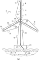
- Fig.1 represents a diagram of a flying drone 1, also called unmanned aerial vehicle (UAV).
- the flying drone 1 may have several propellers 3, for example four propellers 3 arranged in four arms of the flying drone 1 but other configurations with a different number of propellers 3 may also be used.
- the flying drone 1 also comprises at least one positioning system 5 so that the flying drone 1 can fly to the equipment that has to be inspected and detect a lightning receptor 9 located on the equipment.
- the equipment to be inspected refers for example to a wind turbine 7 as represented in Fig.2 .
- the wind turbine 7 may be part of an offshore wind farm comprising a plurality of wind turbines 7 that need to be inspected successively and regularly.
- the flying drone 1 may comprise a first positioning system 5a such as a positioning system based on a global positioning system "GPS" technology in order to enable the flying drone 1 to fly from a docking station, which may be located on a service offshore vessel, to the targeted equipment, for example a wind turbine 7.
- the flying drone 1 may also comprise a second positioning system 5b such as a positioning system based on a light detection and ranging "LIDAR” technology to enable the flying drone 1 to determine its position with respect to the equipment to be inspected.
- a first positioning system 5a such as a positioning system based on a global positioning system "GPS” technology in order to enable the flying drone 1 to fly from a docking station, which may be located on a service offshore vessel, to the targeted equipment, for example a wind turbine 7.
- the flying drone 1 may also comprise a second positioning system 5b such as a positioning system based on a light detection and ranging "LIDAR" technology to enable the flying drone 1 to determine its position with respect to the equipment to be
- the position of the wind turbine 7 may vary depending on the waves, the wind and the sea currents in addition to the position of the blades 9 with respect to the mast 19 (even if this parameter may be controlled) so that a GPS device 5a may not enable the flying drone 1 to detect accurately its position relative to the lightning receptors 11 of the wind turbine 7.
- a LIDAR device 5b may then enable the flying drone 1 to detect the position of the blades 9 and therefore to determine the position of the lightning receptors 11 located on the blades 9 of the wind turbine 7 (the 3D model of the wind turbine 7 may be registered in a memory of the flying drone 1).
- the flying drone 1 may also comprise an optical detector 13 such as a camera or a video recorder associated with a processing unit 15 configured for analyzing the images taken by the optical detector 13 to detect a lightning receptor 11 on a blade 9 of the wind turbine 7.
- an identification label is associated with a lightning receptor 11.
- the identification label may refer to a quick response "QR" code or a barcode or any other identifiable designs which can be engraved on the lightning receptor 11 or stuck next to the lightning receptor 11 (for example above the lightning receptor 11).
- the flying drone 1 may then be equipped with a detector such as an optical detector 13 configured to detect the identification label and therefore to locate and/or identify the associated lightning receptor 11.
- the identification label may refer to a radio frequency identification "RFID” label arranged next to the lightning receptor 11 and the flying drone 1 may be equipped with a RFID reader to detect the RFID label and therefore to locate and identify the associated lightning receptor 11.
- RFID radio frequency identification
- Fig.2 is an embodiment of a wind turbine 7 comprising lightning receptors 11 arranged along the blades 9 of the wind turbine 7.
- the wind turbine 7 comprises three blades 9 arranged rotatably around a hub 17 located on a mast 19.
- the mast 19 may be arranged on a floating structure 21 which is moored to the sea floor, for example via moored lines 25 such as cables.
- a plurality of lightning receptors 11, three lightning receptors 11 in the present example, are arranged on a side of a blade 9 (lightning receptors 11 are generally arranged on both sides of the blade 9).
- a different number of lightning receptors 11 such as a single lightning receptor 11 may be arranged on a blade 9.
- the lightning receptors 11 may be made of a copper chip integrated in the blade 9.
- the copper chip has for example a diameter of a few centimeters.
- the different lightning receptors 11 are connected to the electrical ground (associated for example with a mooring line 25 of the floating structure 21 or the ground or the sea) via an electrical conductor 23 such as a cable linking the different lightning receptors 11 and lying through the mast 19 to the floating structure 21.
- the electrical conductor 23 may also be made of carbon fiber elements or a combination of cables and carbon fiber elements connected together to provide electrical conduction from the different lightning receptors 11 to the electrical ground.
- the electrical conductor 23 may be implemented with a turning joint and brushes to ensure the electrical contact between the static part and the rotating parts of the hub 17.
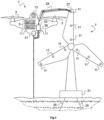
- the flying drone 1 is also equipped with a probe 27 configured to be brought into contact with a lightning receptor 11 as represented in Fig.3 .
- the probe 27 may be arranged on a retractable arm 29 such as an articulated and/or telescopic arm 29. Alternatively, the probe 27 may be stationary with respect to the flying drone 1.
- the flying drone 1 is also equipped with a femtosecond laser 31 which is arranged on the flying drone 1 for transmitting femtosecond pulses directed towards the ground.
- the direction of the ground refers herein to a direction towards the center of the earth but the ground may correspond to the sea or the ocean, for example in the case of an offshore wind farm.
- the duration of the pulse transmitted by the femtosecond laser 31 is chosen so that the energy of the pulse produces a ionization of at least one gaseous species of the air (located between the flying drone 1 and the ground (which can be the sea or the ocean)) so that a plasma is formed between the flying drone 1 and the ground when a pulse is transmitted by the femtosecond laser 31.
- the duration of the pulse is for example comprised between 10 and a few hundreds of femtoseconds.
- the wavelength of the femtosecond laser 31 is comprised between 800nm and 1300nm, preferably from 850nm to 1200nm.
- the flying drone 1 is also equipped with an electrical conductor 33 having a first end 33a linked to the probe 27 and a second end 33b arranged in the radiance of the femtosecond laser 31.
- the electrical conductor 33 is for example made of a cable such as a copper cable.
- the flying drone 1 also comprises a measuring unit 35 associated with the electrical conductor 33 and configured for measuring an electrical resistance along the electrical conductor 33.
- the flying drone 1 may also comprise communication means 37 for communicating with a distant device such as a distant server or its associated docking station.
- the different equipments of the flying drone 1 may be connected to the processing unit 15.
- the processing unit 15 is configured for controlling the flying drone 1 in order to fly the drone 1 towards a selected lightning receptor 11, for contacting the probe 27 with the selected lightning receptor 11 as represented in Fig.3 , for transmitting pulses (represented by the dotted line in Fig.3 ) from the femtosecond laser 31 towards the ground and for measuring an electrical resistance along the electrical conductor 33 with the measuring unit 35.
- the present invention also refers to a method for checking a lightning protection equipment such as the lightning protection equipment of a wind turbine 9.
- the lightning protection equipment refers to the set comprising the lightning receptors 11 and the electrical conductor 23 linking the lightning receptors 11 to the electrical ground associated with the mooring lines 25 (alternatively associated with the ground or the sea).
- the method is achieved with the flying drone 1, described previously.
- Fig.4 represents a flowchart of the different steps of the method.
- the first step 101 refers to the displacement of the flying drone 1 from its docking station or from a predetermined location towards the equipment comprising the lightning protection equipment, in our example a lightning receptor 11 of a blade 9 of a wind turbine 7. Such displacement is achieved thanks to the first positioning system 5a, for example a GPS chip.
- the second step 102 refers to the location of a selected lightning receptor 11.
- the flying drone 1 may check the different lightning receptors 11 sequentially, one after the other.
- the location of the lightning receptor 11 may be achieved by a second positioning system 5b, for example a LIDAR chip and/or an optical detector 13 such as a camera.
- An identification label such as a QR code or a RFID label may be associated with the lightning receptor 11 and the flying drone 1 may be equipped with a detector of the said identification label such as a camera 13 or a RFID reader to ease the identification and location of the lightning receptors 11.
- the third step 103 refers to the positioning of the probe 27 in contact with the selected lightning receptor 11 located in step 102.
- the third step 103 may comprise a sub-step of deploying the arm 29 holding the probe 27.
- the drone 1 then flies to set the probe 27 into contact with the selected lightning receptor 11.
- the fourth step 104 refers to the transmission of femtosecond pulses by the femtosecond laser 31 towards the ground while the probe 27 is in contact with the lightning receptor 11.
- ground it is referred to a direction towards the center of the earth even if the flying drone 1 is located above the sea or the ocean.
- the femtosecond pulses are configured for irradiating an end 33b of the electrical conductor 33 linked to the probe 27.
- the femtosecond laser 31 is configured so that the transmitted pulses produce an ionization of at least one gaseous species of the air. Such ionization leads to the formation of a plasma between the flying drone 1, in particular the electrical conductor 33, and the ground.
- Plasma lifespan resulting from a femtosecond laser pulse traditionally lasts tens to hundreds of microseconds, that is longer than the laser pulse itself.
- pulse frequency ranges from 10 to 100 MHz, one may achieve a continuous plasma string. Accordingly, cheap electrical resistance measurement, acquisition and processing means may be used in the present invention using conventional commercial parts and products.
- the fifth step 105 refers to the measurement of an electrical resistance within the electrical conductor 33 by the measuring unit 35 when the femtosecond pulse is transmitted towards the ground by the femtosecond laser 31.
- the sixth step 106 refers to the comparison of the measured electrical resistance with a predetermined threshold. Such comparison enables checking the correct functioning of the lightning protection equipment. Indeed, the formation of a plasma between the electrical conductor 33 and the ground leads to the formation of an electrical loop between the ground and the measuring unit 35 with one side of the loop associated with the plasma formed by the femtosecond pulse and the other side of the loop associated with the lightning protection equipment, in the present case the electrical conductor 23 linking the lightning receptor 11 to the ground within the wind turbine 7.
- the resistance within the electrical conductor 33 and the plasma formed by the femtosecond pulse are very small, for example a few milliohms.
- a resistance higher than a predetermined threshold for example a few ohms
- a predetermined threshold for example a few ohms
- the different lightning receptors 11 of the wind turbine 7 may be checked successively by applying again some or all of the different steps of the method.
- the flying drone 1 may check the lightning protection equipment of another wind turbine 7 or another equipment or may go back to its docking station. If the flying drone does not comprise communication means for a distant server, the flying drone may transfer the results of the checking method to a processing unit of its docking station when back to the said docking station, such as the measured resistance, then the processing unit of the docking station may compare the received measured resistance with a predetermined threshold and may emit an alarm for the lightning receptors 11 having an associated measured resistance higher than the predetermined threshold in order to apply a maintenance procedure, for example by sending an operator on site.
- a flying drone 1 equipped with a probe 27 configured to set a contact with a lighting receptor 11, a femtosecond laser 31 configured for creating a plasma towards the ground and a measuring unit 35 configured for measuring an electrical resistance in the loop created between the probe 27 and the ground enables checking the correct functioning of a lightning protection equipment.
Landscapes
- Physics & Mathematics (AREA)
- Electromagnetism (AREA)
- General Physics & Mathematics (AREA)
- Elimination Of Static Electricity (AREA)
Abstract
The present invention refers to a flying drone (1) for checking lightning protection equipment (11, 23) comprising:
- a femtosecond laser (31),
- a probe (27),
- an electrical conductor (33) having a first end (33a) linked to the probe (27) and a second end (33b) arranged in the radiance of the femtosecond laser (31),
- a measuring unit (35) configured for measuring an electrical resistance along the electrical conductor (33),
- a processing unit (15),
wherein the processing unit (15) is configured:
- for controlling the flying drone (1) to set the probe (27) in contact with a lightning receptor (11) of a lightning protection equipment (11, 23),
- for controlling the femtosecond laser (31) to transmit a femtosecond pulse directed towards the ground while the probe (27) is in contact with the lightning receptor (11) and,
- for controlling the measuring unit (35) to measure an electrical resistance along the electrical conductor (33) during the transmission of the femtosecond pulse towards the ground.
- a femtosecond laser (31),
- a probe (27),
- an electrical conductor (33) having a first end (33a) linked to the probe (27) and a second end (33b) arranged in the radiance of the femtosecond laser (31),
- a measuring unit (35) configured for measuring an electrical resistance along the electrical conductor (33),
- a processing unit (15),
wherein the processing unit (15) is configured:
- for controlling the flying drone (1) to set the probe (27) in contact with a lightning receptor (11) of a lightning protection equipment (11, 23),
- for controlling the femtosecond laser (31) to transmit a femtosecond pulse directed towards the ground while the probe (27) is in contact with the lightning receptor (11) and,
- for controlling the measuring unit (35) to measure an electrical resistance along the electrical conductor (33) during the transmission of the femtosecond pulse towards the ground.
Description
- The field of the present invention refers to the inspection of lightning protection equipment in particular of lightning protection equipment of wind turbine blades, for example in offshore wind farms.
- Lightnings may cause severe damages to constructions such as wind turbines. To prevent such damages, large constructions are usually equipped with lightning protection devices configured to forward the energy of the lightning towards the ground.
- In the case of wind turbines, the lightning protection devices may be made of lightning receptors made of a conductive material such as copper, which are distributed on the blade, the said lightning receptors being linked to the ground through a conductive pass, for example through a cable or through carbon fiber elements or a mix of these elements.
- However, due to the mechanical constraints undergone by the blades under the effects of the wind or the waves or due to a former lightning, the lightning protection device may be inoperable, for example because of a discontinuity of the conductive pass from the lightning receptor to the ground. It is therefore necessary to regularly check the correct functioning of the lightning protection device.
- To this end, a known solution to test the different lighting receptors is to use a drone linked to the ground by a cable and to measure the resistance between the lightning receptors and the ground by flying the drone from one receptor to the other. However, such solution may be particularly difficult to set up notably in offshore wind farm due to the management of the cable linked to the drone in particular in windy conditions.
- It appears therefore necessary to find a solution to ease the checking of the lightning protection devices made by drones on large constructions such as wind turbines.
- The present invention aims therefore at providing such a solution.
- The present invention refers to a flying drone for checking lightning protection equipment comprising:
- a femtosecond laser,
- a probe,
- an electrical conductor having a first end linked to the probe and a second end arranged in the radiance of the femtosecond laser,
- a measuring unit configured for measuring an electrical resistance along the electrical conductor,
- a processing unit,
- for controlling the flying drone to set the probe in contact with a lightning receptor of a lightning protection equipment,
- for controlling the femtosecond laser to transmit a femtosecond pulse directed towards the ground while the probe is in contact with the lightning receptor and,
- for controlling the measuring unit to measure an electrical resistance along the electrical conductor during the transmission of the femtosecond pulse towards the ground.
- According to another aspect of the invention, the processing unit is also configured for comparing the measured electrical resistance with a predetermined value and for emitting an alarm if the measured value is higher than the predetermined value.
- According to another aspect of the invention, the duration of the transmitted pulse is chosen so that the energy of the pulse produces an ionization of at least one gaseous species of the air and so that a plasma is formed between the drone and the ground.
- According to another aspect of the invention, the transmitted pulse has a duration comprised between ten and hundreds of femtoseconds.
- According to another aspect of the invention, the wavelength of the femtosecond laser is comprised between 800nm and 1300nm, preferably from 850nm to 1200nm.
- According to another aspect of the invention, the probe is located on a retractable arm of the flying drone.
- According to another aspect of the invention, the drone comprises a positioning system to determine its position with respect to the lightning receptor, for example a positioning system based on a light detection and ranging "LIDAR" technology and/or an optical detector such as a camera or video recorder.
- According to another aspect of the invention, the flying drone comprises a detector configured for detecting an identification label associated with a lightning receptor to locate and/or identify the lightning receptor.
- According to another aspect of the invention, the identification label refers to a quick response "QR" code or a barcode and the detector refers to a camera or video recorder.
- According to another aspect of the invention, the identification label refers to a radio frequency identification "RFID" label and the detector (13) refers to a RFID reader.
- The present invention also refers to a method for checking lightning protection equipment comprising the following steps:
- flying a drone equipped with a probe and a femtosecond laser towards a lightning protection equipment, the probe being electrically connected to the femtosecond laser radiance by an electrical conductor,
- setting the probe in contact with a lightning receptor of a lightning protection equipment,
- transmitting, by the femtosecond laser, a femtosecond pulse directed towards the ground while the probe is in contact with the lightning receptor and,
- measuring an electrical resistance of the electrical conductor during the transmission of the femtosecond pulse.
- According to another aspect of the invention, the method also comprises the following steps:
- comparing the measured electrical resistance with a predetermined value and,
- emitting an alarm if the measured value is higher than the predetermined value.
-
- [
Fig.1 ] is a diagram of a flying drone according to the present invention; - [
Fig.2 ] is a diagram of a wind turbine; - [
Fig.3 ] is a diagram of the flying drone ofFig. 1 while checking the lightning protection equipment of the wind turbine ofFig.2 ; - [
Fig.4 ] is a flowchart of the different steps of the method for checking a lightning protection equipment. - The following achievements are examples. Although the specification refers to one or several embodiments, it does not imply that each reference refers to the same embodiment or that the features apply only to a single embodiment. Simple features of different embodiments can also be combined to provide other embodiments.
-
Fig.1 represents a diagram of aflying drone 1, also called unmanned aerial vehicle (UAV). Theflying drone 1 may haveseveral propellers 3, for example fourpropellers 3 arranged in four arms of theflying drone 1 but other configurations with a different number ofpropellers 3 may also be used. Theflying drone 1 also comprises at least onepositioning system 5 so that theflying drone 1 can fly to the equipment that has to be inspected and detect alightning receptor 9 located on the equipment. The equipment to be inspected refers for example to awind turbine 7 as represented inFig.2 . Thewind turbine 7 may be part of an offshore wind farm comprising a plurality ofwind turbines 7 that need to be inspected successively and regularly. - Thus, the
flying drone 1 may comprise afirst positioning system 5a such as a positioning system based on a global positioning system "GPS" technology in order to enable theflying drone 1 to fly from a docking station, which may be located on a service offshore vessel, to the targeted equipment, for example awind turbine 7. Theflying drone 1 may also comprise asecond positioning system 5b such as a positioning system based on a light detection and ranging "LIDAR" technology to enable theflying drone 1 to determine its position with respect to the equipment to be inspected. Indeed, in the case of anoffshore wind turbine 7, the position of thewind turbine 7 may vary depending on the waves, the wind and the sea currents in addition to the position of theblades 9 with respect to the mast 19 (even if this parameter may be controlled) so that aGPS device 5a may not enable theflying drone 1 to detect accurately its position relative to thelightning receptors 11 of thewind turbine 7. A LIDARdevice 5b may then enable theflying drone 1 to detect the position of theblades 9 and therefore to determine the position of thelightning receptors 11 located on theblades 9 of the wind turbine 7 (the 3D model of thewind turbine 7 may be registered in a memory of the flying drone 1). Alternatively or additionally, theflying drone 1 may also comprise anoptical detector 13 such as a camera or a video recorder associated with aprocessing unit 15 configured for analyzing the images taken by theoptical detector 13 to detect alightning receptor 11 on ablade 9 of thewind turbine 7. - According to an embodiment, an identification label is associated with a
lightning receptor 11. The identification label may refer to a quick response "QR" code or a barcode or any other identifiable designs which can be engraved on thelightning receptor 11 or stuck next to the lightning receptor 11 (for example above the lightning receptor 11). Theflying drone 1 may then be equipped with a detector such as anoptical detector 13 configured to detect the identification label and therefore to locate and/or identify the associatedlightning receptor 11. Alternatively, the identification label may refer to a radio frequency identification "RFID" label arranged next to thelightning receptor 11 and theflying drone 1 may be equipped with a RFID reader to detect the RFID label and therefore to locate and identify the associatedlightning receptor 11. Such identification labels enable easing the location and the identification of thedifferent lightning receptors 11 by theflying drone 1. -
Fig.2 is an embodiment of awind turbine 7 comprisinglightning receptors 11 arranged along theblades 9 of thewind turbine 7. In this example, thewind turbine 7 comprises threeblades 9 arranged rotatably around ahub 17 located on amast 19. In the case of an offshore wind farm, themast 19 may be arranged on a floatingstructure 21 which is moored to the sea floor, for example via mooredlines 25 such as cables. A plurality oflightning receptors 11, threelightning receptors 11 in the present example, are arranged on a side of a blade 9 (lightning receptors 11 are generally arranged on both sides of the blade 9). However, a different number oflightning receptors 11 such as asingle lightning receptor 11 may be arranged on ablade 9. Thelightning receptors 11 may be made of a copper chip integrated in theblade 9. The copper chip has for example a diameter of a few centimeters. Thedifferent lightning receptors 11 are connected to the electrical ground (associated for example with amooring line 25 of the floatingstructure 21 or the ground or the sea) via anelectrical conductor 23 such as a cable linking thedifferent lightning receptors 11 and lying through themast 19 to the floatingstructure 21. Theelectrical conductor 23 may also be made of carbon fiber elements or a combination of cables and carbon fiber elements connected together to provide electrical conduction from thedifferent lightning receptors 11 to the electrical ground. Within thehub 17, theelectrical conductor 23 may be implemented with a turning joint and brushes to ensure the electrical contact between the static part and the rotating parts of thehub 17. - The flying
drone 1 is also equipped with aprobe 27 configured to be brought into contact with alightning receptor 11 as represented inFig.3 . Theprobe 27 may be arranged on aretractable arm 29 such as an articulated and/ortelescopic arm 29. Alternatively, theprobe 27 may be stationary with respect to the flyingdrone 1. - The flying
drone 1 is also equipped with afemtosecond laser 31 which is arranged on the flyingdrone 1 for transmitting femtosecond pulses directed towards the ground. The direction of the ground refers herein to a direction towards the center of the earth but the ground may correspond to the sea or the ocean, for example in the case of an offshore wind farm. - The duration of the pulse transmitted by the
femtosecond laser 31 is chosen so that the energy of the pulse produces a ionization of at least one gaseous species of the air (located between the flyingdrone 1 and the ground (which can be the sea or the ocean)) so that a plasma is formed between the flyingdrone 1 and the ground when a pulse is transmitted by thefemtosecond laser 31. The duration of the pulse is for example comprised between 10 and a few hundreds of femtoseconds. The wavelength of thefemtosecond laser 31 is comprised between 800nm and 1300nm, preferably from 850nm to 1200nm. - The flying
drone 1 is also equipped with anelectrical conductor 33 having afirst end 33a linked to theprobe 27 and asecond end 33b arranged in the radiance of thefemtosecond laser 31. Theelectrical conductor 33 is for example made of a cable such as a copper cable. - The flying
drone 1 also comprises a measuringunit 35 associated with theelectrical conductor 33 and configured for measuring an electrical resistance along theelectrical conductor 33. - The flying
drone 1 may also comprise communication means 37 for communicating with a distant device such as a distant server or its associated docking station. - The different equipments of the flying
drone 1 may be connected to theprocessing unit 15. - The
processing unit 15 is configured for controlling the flyingdrone 1 in order to fly thedrone 1 towards a selectedlightning receptor 11, for contacting theprobe 27 with the selectedlightning receptor 11 as represented inFig.3 , for transmitting pulses (represented by the dotted line inFig.3 ) from thefemtosecond laser 31 towards the ground and for measuring an electrical resistance along theelectrical conductor 33 with the measuringunit 35. - The present invention also refers to a method for checking a lightning protection equipment such as the lightning protection equipment of a
wind turbine 9. In the example ofFig.2 , the lightning protection equipment refers to the set comprising thelightning receptors 11 and theelectrical conductor 23 linking thelightning receptors 11 to the electrical ground associated with the mooring lines 25 (alternatively associated with the ground or the sea). The method is achieved with the flyingdrone 1, described previously. -
Fig.4 represents a flowchart of the different steps of the method. - The
first step 101 refers to the displacement of the flyingdrone 1 from its docking station or from a predetermined location towards the equipment comprising the lightning protection equipment, in our example alightning receptor 11 of ablade 9 of awind turbine 7. Such displacement is achieved thanks to thefirst positioning system 5a, for example a GPS chip. - The
second step 102 refers to the location of a selectedlightning receptor 11. In the case of a plurality oflightning receptors 11 to check, the flyingdrone 1 may check thedifferent lightning receptors 11 sequentially, one after the other. The location of thelightning receptor 11 may be achieved by asecond positioning system 5b, for example a LIDAR chip and/or anoptical detector 13 such as a camera. An identification label such as a QR code or a RFID label may be associated with thelightning receptor 11 and the flyingdrone 1 may be equipped with a detector of the said identification label such as acamera 13 or a RFID reader to ease the identification and location of thelightning receptors 11. - The
third step 103 refers to the positioning of theprobe 27 in contact with the selectedlightning receptor 11 located instep 102. Thethird step 103 may comprise a sub-step of deploying thearm 29 holding theprobe 27. Thedrone 1 then flies to set theprobe 27 into contact with the selectedlightning receptor 11. - The
fourth step 104 refers to the transmission of femtosecond pulses by thefemtosecond laser 31 towards the ground while theprobe 27 is in contact with thelightning receptor 11. By ground it is referred to a direction towards the center of the earth even if the flyingdrone 1 is located above the sea or the ocean. The femtosecond pulses are configured for irradiating anend 33b of theelectrical conductor 33 linked to theprobe 27. Thefemtosecond laser 31 is configured so that the transmitted pulses produce an ionization of at least one gaseous species of the air. Such ionization leads to the formation of a plasma between the flyingdrone 1, in particular theelectrical conductor 33, and the ground. Plasma lifespan resulting from a femtosecond laser pulse traditionally lasts tens to hundreds of microseconds, that is longer than the laser pulse itself. In addition, considering most of available commercial femtosecond laser devices, pulse frequency ranges from 10 to 100 MHz, one may achieve a continuous plasma string. Accordingly, cheap electrical resistance measurement, acquisition and processing means may be used in the present invention using conventional commercial parts and products. - The
fifth step 105 refers to the measurement of an electrical resistance within theelectrical conductor 33 by the measuringunit 35 when the femtosecond pulse is transmitted towards the ground by thefemtosecond laser 31. - The
sixth step 106 refers to the comparison of the measured electrical resistance with a predetermined threshold. Such comparison enables checking the correct functioning of the lightning protection equipment. Indeed, the formation of a plasma between theelectrical conductor 33 and the ground leads to the formation of an electrical loop between the ground and the measuringunit 35 with one side of the loop associated with the plasma formed by the femtosecond pulse and the other side of the loop associated with the lightning protection equipment, in the present case theelectrical conductor 23 linking thelightning receptor 11 to the ground within thewind turbine 7. The resistance within theelectrical conductor 33 and the plasma formed by the femtosecond pulse are very small, for example a few milliohms. Thus, if a resistance higher than a predetermined threshold, for example a few ohms, is measured by the measuringunit 35, it may mean that the lightning protection equipment presents a failure such as a discontinuity of theelectrical conductor 23. In such case, an alarm may be transmitted by theprocessing unit 15 towards a distant server to warn operators about a possible failure of the lightning protection equipment. - The
different lightning receptors 11 of thewind turbine 7 may be checked successively by applying again some or all of the different steps of the method. When all thelightning receptors 11 of awind turbine 7 are checked, the flyingdrone 1 may check the lightning protection equipment of anotherwind turbine 7 or another equipment or may go back to its docking station. If the flying drone does not comprise communication means for a distant server, the flying drone may transfer the results of the checking method to a processing unit of its docking station when back to the said docking station, such as the measured resistance, then the processing unit of the docking station may compare the received measured resistance with a predetermined threshold and may emit an alarm for thelightning receptors 11 having an associated measured resistance higher than the predetermined threshold in order to apply a maintenance procedure, for example by sending an operator on site. - Thus, the use of a flying
drone 1 equipped with aprobe 27 configured to set a contact with alighting receptor 11, afemtosecond laser 31 configured for creating a plasma towards the ground and a measuringunit 35 configured for measuring an electrical resistance in the loop created between theprobe 27 and the ground enables checking the correct functioning of a lightning protection equipment.
Claims (12)
- Flying drone (1) for checking lightning protection equipment (11, 23) comprising:- a femtosecond laser (31),- a probe (27),- an electrical conductor (33) having a first end (33a) linked to the probe (27) and a second end (33b) arranged in the radiance of the femtosecond laser (31),- a measuring unit (35) configured for measuring an electrical resistance along the electrical conductor (33),- a processing unit (15),wherein the processing unit (15) is configured:- for controlling the flying drone (1) to set the probe (27) in contact with a lightning receptor (11) of a lightning protection equipment (11, 23),- for controlling the femtosecond laser (31) to transmit a femtosecond pulse directed towards the ground while the probe (27) is in contact with the lightning receptor (11) and,- for controlling the measuring unit (35) to measure an electrical resistance along the electrical conductor (33) during the transmission of the femtosecond pulse towards the ground.
- Flying drone (1) in accordance with claim 1 wherein the processing unit (15) is also configured for comparing the measured electrical resistance with a predetermined value and for emitting an alarm if the measured value is higher than the predetermined value.
- Flying drone (1) in accordance with one of the previous claims wherein the duration of the transmitted pulse of the femtosecond laser (31) is chosen so that the energy of the pulse produces an ionization of at least one gaseous species of the air and so that a plasma is formed between the flying drone (1) and the ground.
- Flying drone (1) in accordance with the previous claim wherein the transmitted pulse of the femtosecond laser (31) has a duration comprised between ten and hundreds of femtoseconds.
- Flying drone (1) in accordance with one of the previous claims wherein the wavelength of the femtosecond laser (31) is comprised between 800nm and 1300nm, preferably from 850nm to 1200nm.
- Flying drone (1) in accordance with one of the previous claims wherein the probe (27) is located on a retractable arm (29) of the flying drone (1).
- Flying drone (1) in accordance with one of the previous claims wherein the drone (1) comprises a positioning system (5, 5a, 5b, 13) to determine its position with respect to the lightning receptor (11), for example a positioning system based on a light detection and ranging "LIDAR" technology (5b) and/or an optical detector (13) such as a camera or video recorder.
- Flying drone (1) in accordance with one of the previous claims wherein the flying drone (1) comprises a detector (13) configured for detecting an identification label associated with a lightning receptor (11) to locate and/or identify the lightning receptor (11).
- Flying drone (1) in accordance with the previous claim wherein the identification label refers to a quick response "QR" code or a barcode and the detector (13) refers to a camera or video recorder.
- Flying drone (1) in accordance with one of the claims 1 to 8 wherein the identification label refers to a radio frequency identification "RFID" label and the detector (13) refers to a RFID reader.
- Method for checking a lightning protection equipment comprising the following steps:- flying a drone (1), equipped with a probe (27) and a femtosecond laser (31), towards the lightning protection equipment, the probe (27) being electrically connected to the femtosecond laser (31) radiance by an electrical conductor (33), (101)- setting the probe (27) in contact with a lightning receptor (11) of the lightning protection equipment, (103)- transmitting, by the femtosecond laser (31), a femtosecond pulse directed towards the ground (104) while the probe (27) is in contact with the lightning receptor (11) and,- measuring an electrical resistance of the electrical conductor (33) during the transmission of the femtosecond pulse (105).
- Method in accordance with the previous claim wherein it also comprises the following steps:- comparing the measured electrical resistance with a predetermined value (106) and,- transmitting an alarm if the measured value is higher than the predetermined value.
Priority Applications (2)
| Application Number | Priority Date | Filing Date | Title |
|---|---|---|---|
| EP23315293.3A EP4498101A1 (en) | 2023-07-24 | 2023-07-24 | Flying drone for checking lightning equipment and associated method |
| PCT/EP2024/070321 WO2025021627A1 (en) | 2023-07-24 | 2024-07-17 | Flying drone for checking lightning equipment and associated method |
Applications Claiming Priority (1)
| Application Number | Priority Date | Filing Date | Title |
|---|---|---|---|
| EP23315293.3A EP4498101A1 (en) | 2023-07-24 | 2023-07-24 | Flying drone for checking lightning equipment and associated method |
Publications (1)
| Publication Number | Publication Date |
|---|---|
| EP4498101A1 true EP4498101A1 (en) | 2025-01-29 |
Family
ID=87695852
Family Applications (1)
| Application Number | Title | Priority Date | Filing Date |
|---|---|---|---|
| EP23315293.3A Withdrawn EP4498101A1 (en) | 2023-07-24 | 2023-07-24 | Flying drone for checking lightning equipment and associated method |
Country Status (2)
| Country | Link |
|---|---|
| EP (1) | EP4498101A1 (en) |
| WO (1) | WO2025021627A1 (en) |
Citations (2)
| Publication number | Priority date | Publication date | Assignee | Title |
|---|---|---|---|---|
| US20200291926A1 (en) * | 2019-03-14 | 2020-09-17 | Siemens Gamesa Renewable Energy A/S | Method for providing a wind turbine blade with lightning protection and a wind turbine blade |
| JP2022183996A (en) * | 2021-05-31 | 2022-12-13 | 関西電力株式会社 | Inspection method and unmanned inspection device for wind power generation equipment |
-
2023
- 2023-07-24 EP EP23315293.3A patent/EP4498101A1/en not_active Withdrawn
-
2024
- 2024-07-17 WO PCT/EP2024/070321 patent/WO2025021627A1/en not_active Ceased
Patent Citations (2)
| Publication number | Priority date | Publication date | Assignee | Title |
|---|---|---|---|---|
| US20200291926A1 (en) * | 2019-03-14 | 2020-09-17 | Siemens Gamesa Renewable Energy A/S | Method for providing a wind turbine blade with lightning protection and a wind turbine blade |
| JP2022183996A (en) * | 2021-05-31 | 2022-12-13 | 関西電力株式会社 | Inspection method and unmanned inspection device for wind power generation equipment |
Also Published As
| Publication number | Publication date |
|---|---|
| WO2025021627A1 (en) | 2025-01-30 |
Similar Documents
| Publication | Publication Date | Title |
|---|---|---|
| KR102553453B1 (en) | Apparatus and method of unmaned aerial vehicle for power facilities inspection monitoring | |
| CN114109738B (en) | Monitoring system for a wind turbine blade, wind turbine arrangement and method for monitoring a wind turbine blade | |
| US7881869B2 (en) | Method and apparatus for evaluating data associated with an offshore energy platform | |
| HK1215464A1 (en) | Unmanned flying device and method for performing a lightning protection measurement on a wind energy plant | |
| KR20200009310A (en) | Apparatus and method for monitoring power facilities | |
| CN109376587A (en) | Communication iron tower intelligent inspection system and method are surveyed in detection based on Internet of Things | |
| EP4093968B1 (en) | Method for testing a lightning protection system and/or a lightning detection system of a wind turbine | |
| US10075232B1 (en) | Detecting fiber optic breaks using autonomous vehicles | |
| CN109541613A (en) | Aerial high-voltage conducting wire cruising inspection system and method for inspecting based on single line laser ranging | |
| CN114508464B (en) | A wind turbine blade lead wire breakage online monitoring system and positive and negative testing method | |
| CN109406570A (en) | A kind of composite insulator aging optical heat radiation detection system based on unmanned plane | |
| CN217954608U (en) | Overhead line ground fault finding device based on unmanned aerial vehicle | |
| CN115892451B (en) | On-site operation risk management and control system and method for unmanned aerial vehicle monitoring | |
| WO2022268276A1 (en) | Detecting lightning strikes on a wind turbine with improved reliability | |
| WO2025021627A1 (en) | Flying drone for checking lightning equipment and associated method | |
| CN117353658B (en) | IV&CV Fusion Diagnostic System | |
| US20250028008A1 (en) | Device, system and method for performing a continuity test of an electrical line of an object | |
| US11038384B2 (en) | Monitoring of power systems using unmanned vehicle | |
| CN212432995U (en) | Online non-contact blade detection device based on terahertz technology | |
| JP7818552B2 (en) | Inspection methods for wind power generation equipment | |
| EP4390122A1 (en) | Equipment for inspecting wind turbines of an offshore wind farm and associated method | |
| CN117833095A (en) | Inspection equipment | |
| EP4653697A1 (en) | Lightning protection equipment and associated method | |
| CN216870791U (en) | Radio monitoring direction-finding equipment based on many rotor unmanned aerial vehicle aircraft | |
| JP2021143600A (en) | Pull-down conductor continuity inspection method in blade of wind power generation device |
Legal Events
| Date | Code | Title | Description |
|---|---|---|---|
| PUAI | Public reference made under article 153(3) epc to a published international application that has entered the european phase |
Free format text: ORIGINAL CODE: 0009012 |
|
| STAA | Information on the status of an ep patent application or granted ep patent |
Free format text: STATUS: THE APPLICATION HAS BEEN PUBLISHED |
|
| AK | Designated contracting states |
Kind code of ref document: A1 Designated state(s): AL AT BE BG CH CY CZ DE DK EE ES FI FR GB GR HR HU IE IS IT LI LT LU LV MC ME MK MT NL NO PL PT RO RS SE SI SK SM TR |
|
| STAA | Information on the status of an ep patent application or granted ep patent |
Free format text: STATUS: THE APPLICATION IS DEEMED TO BE WITHDRAWN |
|
| 18D | Application deemed to be withdrawn |
Effective date: 20250730 |