EP4498089A1 - Automatic analysis system - Google Patents
Automatic analysis system Download PDFInfo
- Publication number
- EP4498089A1 EP4498089A1 EP22932497.5A EP22932497A EP4498089A1 EP 4498089 A1 EP4498089 A1 EP 4498089A1 EP 22932497 A EP22932497 A EP 22932497A EP 4498089 A1 EP4498089 A1 EP 4498089A1
- Authority
- EP
- European Patent Office
- Prior art keywords
- specimen
- automatic analyzer
- control unit
- conveyance device
- automatic
- Prior art date
- Legal status (The legal status is an assumption and is not a legal conclusion. Google has not performed a legal analysis and makes no representation as to the accuracy of the status listed.)
- Pending
Links
Images






Classifications
-
- G—PHYSICS
- G01—MEASURING; TESTING
- G01N—INVESTIGATING OR ANALYSING MATERIALS BY DETERMINING THEIR CHEMICAL OR PHYSICAL PROPERTIES
- G01N35/00—Automatic analysis not limited to methods or materials provided for in any single one of groups G01N1/00 - G01N33/00; Handling materials therefor
- G01N35/00584—Control arrangements for automatic analysers
- G01N35/0092—Scheduling
-
- G—PHYSICS
- G01—MEASURING; TESTING
- G01N—INVESTIGATING OR ANALYSING MATERIALS BY DETERMINING THEIR CHEMICAL OR PHYSICAL PROPERTIES
- G01N35/00—Automatic analysis not limited to methods or materials provided for in any single one of groups G01N1/00 - G01N33/00; Handling materials therefor
- G01N35/02—Automatic analysis not limited to methods or materials provided for in any single one of groups G01N1/00 - G01N33/00; Handling materials therefor using a plurality of sample containers moved by a conveyor system past one or more treatment or analysis stations
- G01N35/04—Details of the conveyor system
-
- G—PHYSICS
- G01—MEASURING; TESTING
- G01N—INVESTIGATING OR ANALYSING MATERIALS BY DETERMINING THEIR CHEMICAL OR PHYSICAL PROPERTIES
- G01N35/00—Automatic analysis not limited to methods or materials provided for in any single one of groups G01N1/00 - G01N33/00; Handling materials therefor
- G01N35/00584—Control arrangements for automatic analysers
- G01N35/00722—Communications; Identification
- G01N35/00732—Identification of carriers, materials or components in automatic analysers
-
- G—PHYSICS
- G01—MEASURING; TESTING
- G01N—INVESTIGATING OR ANALYSING MATERIALS BY DETERMINING THEIR CHEMICAL OR PHYSICAL PROPERTIES
- G01N35/00—Automatic analysis not limited to methods or materials provided for in any single one of groups G01N1/00 - G01N33/00; Handling materials therefor
- G01N35/00584—Control arrangements for automatic analysers
- G01N35/00722—Communications; Identification
- G01N35/00871—Communications between instruments or with remote terminals
-
- G—PHYSICS
- G01—MEASURING; TESTING
- G01N—INVESTIGATING OR ANALYSING MATERIALS BY DETERMINING THEIR CHEMICAL OR PHYSICAL PROPERTIES
- G01N35/00—Automatic analysis not limited to methods or materials provided for in any single one of groups G01N1/00 - G01N33/00; Handling materials therefor
- G01N35/02—Automatic analysis not limited to methods or materials provided for in any single one of groups G01N1/00 - G01N33/00; Handling materials therefor using a plurality of sample containers moved by a conveyor system past one or more treatment or analysis stations
-
- G—PHYSICS
- G01—MEASURING; TESTING
- G01N—INVESTIGATING OR ANALYSING MATERIALS BY DETERMINING THEIR CHEMICAL OR PHYSICAL PROPERTIES
- G01N35/00—Automatic analysis not limited to methods or materials provided for in any single one of groups G01N1/00 - G01N33/00; Handling materials therefor
- G01N35/00584—Control arrangements for automatic analysers
- G01N35/00722—Communications; Identification
- G01N35/00732—Identification of carriers, materials or components in automatic analysers
- G01N2035/00821—Identification of carriers, materials or components in automatic analysers nature of coded information
- G01N2035/00831—Identification of carriers, materials or components in automatic analysers nature of coded information identification of the sample, e.g. patient identity, place of sampling
-
- G—PHYSICS
- G01—MEASURING; TESTING
- G01N—INVESTIGATING OR ANALYSING MATERIALS BY DETERMINING THEIR CHEMICAL OR PHYSICAL PROPERTIES
- G01N35/00—Automatic analysis not limited to methods or materials provided for in any single one of groups G01N1/00 - G01N33/00; Handling materials therefor
- G01N35/00584—Control arrangements for automatic analysers
- G01N35/00722—Communications; Identification
- G01N35/00732—Identification of carriers, materials or components in automatic analysers
- G01N2035/00821—Identification of carriers, materials or components in automatic analysers nature of coded information
- G01N2035/00851—Identification of carriers, materials or components in automatic analysers nature of coded information process control parameters
-
- G—PHYSICS
- G01—MEASURING; TESTING
- G01N—INVESTIGATING OR ANALYSING MATERIALS BY DETERMINING THEIR CHEMICAL OR PHYSICAL PROPERTIES
- G01N35/00—Automatic analysis not limited to methods or materials provided for in any single one of groups G01N1/00 - G01N33/00; Handling materials therefor
- G01N35/00584—Control arrangements for automatic analysers
- G01N35/00722—Communications; Identification
- G01N35/00871—Communications between instruments or with remote terminals
- G01N2035/00881—Communications between instruments or with remote terminals network configurations
Definitions
- PTL 1 discloses an automatic analysis system in which, when occurrence of an urgent examination is recognized, an automatic analyzer is caused to execute a required preparation process before a specimen measurement, thereby shortening a time.
- the conveyance device 120 includes a preprocessing unit 122 that performs a preprocess on the specimen rack 190 input into a specimen input port 121, and a specimen rack conveyance unit 192 that conveys the specimen rack 190 after being subjected to the preprocess to the automatic analyzer 130.
- the preprocess performed by the preprocessing unit 122 includes, for example, specimen classification, centrifugal separation, unplugging, aliquoting, label attachment, plugging, and storage.
- the standby state is a state in which although the automatic analyzer 130 is energized, a mechanical system for operating an aliquoting probe, a reaction disk, and the like provided in the automatic analyzer 130 is stopped.
- the operation state is a state in which the mechanical system operates and the specimen can be immediately analyzed. That is, when the automatic analyzer 130 is in the standby state, the specimen cannot be analyzed until transitioning to the operation state is completed, and a time for an output of an examination result is required.
- the time required for the output of the examination result is shortened by starting to cause the automatic analyzer 130 to transition from the standby state to the operation state at a timing when patient information of the specimen is registered in the medical information system 101. More specifically, the control unit 111 to which the patient information registered in the medical information system 101 is transmitted starts to cause the automatic analyzer 130 to transition from the standby state to the operation state, and the transitioning proceeds while the specimen rack 190 is conveyed. The transitioning from the standby state to the operation state is started early, so that a time from reception of the specimen to the output of the examination result is shortened.
- a timing when the automatic analyzer 130 is caused to transition from the standby state to the operation state is not limited to the timing when the patient information is registered in the medical information system 101.
- the transitioning of the automatic analyzer 130 from the standby state to the operation state may be started at a timing when the specimen rack 190 is input into the specimen input port 121 of the conveyance device 120.
- the control unit 111 that receives the patient information associated with the identifier attached to the specimen rack 190 input into the specimen input port 121 starts to cause the automatic analyzer 130 to transition from the standby state to the operation state, and the transitioning proceeds while the specimen rack 190 is conveyed.
- the transitioning from the standby state to the operation state is started early, so that the time from the reception of the specimen to the output of the examination result is shortened.
- a start operation which is an operation of causing the automatic analyzer 130 to transition from the standby state to the operation state, includes a reset operation and a confirmation operation.
- the reset operation is an operation of initializing the automatic analyzer 130, and is an operation of returning the units to an initial position or discharging the specimen rack 190 remaining in the automatic analyzer 130.
- the confirmation operation is an operation of confirming that the mechanical system can be operated, and may include an operation of confirming that a liquid surface detection sensor provided in the aliquoting probe is normal.
- the automatic analysis system includes the control unit 111, the automatic analyzer 130, and the conveyance device 120 that are connected by the communication cable 191.
- the control unit 111 and the automatic analyzer 130 have the same configurations as those of Embodiment 1, and thus description thereof will be omitted.
- the conveyance device 120 includes an information reading unit 201, the preprocessing unit 122, and the specimen rack conveyance unit 192.
- the information reading unit 201 is a device that reads an identifier attached to the specimen rack 190 input into the specimen input port 121, and is, for example, a barcode reader or an RFID reader. The identifier of the specimen rack 190 is read immediately after the specimen rack 190 is input into the specimen input port 121.
- the preprocessing unit 122 is a unit that performs the preprocess on the specimen rack 190 input into the specimen input port 121, and includes at least one of a centrifugal separation unit 210, an unplugging unit 211, an aliquoting unit 212, a label attaching unit 213, a plugging unit 214, and a storage unit 215.
- the centrifugal separation unit 210 is a unit that performs the centrifugal separation on a specimen.
- the unplugging unit 211 is a unit that opens a lid of the specimen tube accommodating a specimen.
- the aliquoting unit 212 is a unit that aliquots the specimen accommodated in the specimen tube into other plurality of containers. An original specimen to be aliquoted is referred to as a parent specimen, and the specimen aliquoted into another container is referred to as a child specimen.
- the label attaching unit 213 is a unit that attaches an identifier for identifying the child specimen to the container.
- the plugging unit 214 is a unit that closes the lid of the specimen tube.
- the storage unit 215 is a unit that stores the specimen tube after being subjected to the analysis. These units may be provided in any order.
- the specimen rack conveyance unit 192 is a unit that conveys the specimen rack 190 subjected to various preprocesses to the automatic analyzer 130.
- the specimen rack 190 is input into the specimen input port 121.
- the information reading unit 201 reads the identifier attached to the specimen rack 190 immediately after being input into the specimen input port 121, and transmits the read identifier to the control unit 111.
- the control unit 111 determines presence or absence of a preprocessing operation for the specimen in the specimen rack 190 based on the identifier transmitted from the information reading unit 201. When the preprocessing operation is present, the process proceeds to step 34 and step 35, and when no preprocessing operation is present, the process proceeds to step 38.
- the control unit 111 receives the patient information associated with the identifier transmitted from the information reading unit 201.
- the control unit 111 causes the specimen rack 190 to be conveyed to the preprocessing unit 122, and causes the preprocessing operation to be performed on the specimen in the specimen rack 190.
- the control unit 111 causes the automatic analyzer 130 to execute the reset operation in parallel with step 34.
- the automatic analyzer 130 transitions to the operation state by executing the confirmation operation, and is on standby until the preprocessing operation performed by the preprocessing unit 122 is completed.
- the control unit 111 causes the automatic analyzer 130 to transition to the operation state to start an analysis operation.
- the control unit 111 causes the automatic analyzer 130 to execute the reset operation.
- the automatic analyzer 130 transitions to the operation state by executing the confirmation operation.
- the control unit 111 starts to cause the automatic analyzer 130 to transition from the standby state to the operation state at the timing when the patient information is received from the conveyance device 120. That is, as in Embodiment 1, since the transitioning from the standby state to the operation state is started early, the time from the reception of the specimen to the output of the examination result is shortened. In parallel with the transitioning of the automatic analyzer 130 from the standby state to the operation state, the preprocess is performed in the conveyance device 120, and thus the time from the reception of the specimen to the output of the examination result can be shortened.
- Embodiment 2 describes that the preprocess is performed in the conveyance device 120 in parallel with the transitioning of the automatic analyzer 130 from the standby state to the operation state.
- Embodiment 3 describes that the automatic analyzer 130 is caused to execute an additional maintenance process while the preprocess is performed in the conveyance device 120.
- FIG. 4 A processing flow executed in Embodiment 3 will be described with reference to FIG. 4 .
- steps 41 and 42 are added to FIG. 3 , and the description of steps other than these steps is omitted.
- the control unit 111 calculates a time required for the preprocessing operation in step 34 based on the identifier transmitted from the information reading unit 201, and determines whether an additional maintenance process can be executed. If the additional maintenance process can be executed, the process proceeds to step 42, and if the additional maintenance process cannot be executed, the process proceeds to step 35. Whether the additional maintenance process can be executed is determined based on a comparison between a time Tp required for the preprocessing operation and a time Tm required for the additional maintenance process. That is, if Tp > Tm, it is determined that the additional maintenance process can be executed.
- the control unit 111 causes the automatic analyzer 130 to execute the additional maintenance process.
- the additional maintenance process may be a single process, a process of continuously repeating the single process a plurality of times, or a process of combining different processes.
- the execution of the additional maintenance process improves analysis accuracy of the automatic analyzer 130.
- the cell cleaning prime and the air purge are maintenance processes having relatively short effective times.
- the cleaning in a reagent flow path is a maintenance process of replacing a reagent and the like remaining in a reagent flow path, and is performed a plurality of times when an elapsed time from when the automatic analyzer 130 enters the standby state is long, for example, when the elapsed time is one hour or more.
- the cell cleaning prime is a process of refilling a detergent in a flow path connected to a detergent probe that discharges the detergent to a container of a biological specimen reaction unit.
- the air purge is a process of replacing system water in a flow path connected to a reagent probe for suctioning a reagent with degassed water or removing bubbles in the flow path by continuously flowing pure water.
- the transitioning from the standby state to the operation state is started early, so that the time from the reception of the specimen to the output of the examination result is shortened.
- the preprocess in parallel with the transitioning to the operation state, the preprocess is performed, and thus the time from the reception of the specimen to the output of the examination result can be shortened. Further, the analysis accuracy of the automatic analyzer 130 can be improved by executing the additional maintenance process while the preprocess is performed.
- Embodiment 2 describes that the information reading unit 201 of the conveyance device 120 reads the identifier of the specimen rack 190. When the identifier is read, some errors may occur. In Embodiment 4, a case will be described in which an error occurs at the time of reading the identifier.
- step 32 in FIG. 4 is replaced with step 51, steps 52 and 53 are added, and thus the description of steps other than these steps is omitted.
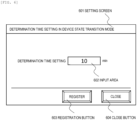
- a setting screen 601 shown in FIG. 6 is a screen for setting a determination time, and includes an input area 602, a registration button 603, and a close button 604.
- the determination time is input to the input area 602.
- the registration button 603 is pressed.
- the close button 604 is pressed.
- a time until the examination result is output is shortened by selectively using the plurality of specimen input ports. More specifically, by inputting the centrifugal required rack 701 into the centrifugal separation input port 710 and inputting the centrifugal unrequired rack 702 into the unplugging input port 720, stagnation of the centrifugal unrequired rack 702 is prevented and the output of the examination result of the specimen is not delayed.
- Arrangement positions of the centrifugal separation input port 710 and the unplugging input port 720 are not limited to the positions shown in FIG. 7 , and may be any positions as long as the positions are upstream of the corresponding preprocessing units.
- the arrangement position of the unplugging input port 720 may be between the centrifugal separation input port 710 and the centrifuge unit 712 or on a left side of the centrifugal separation input port 710.
- the control unit 111 determines the position where the specimen rack is input. When the specimen rack is input into the centrifugal separation input port 710, the process proceeds to step 86, and when the specimen rack is input into the unplugging input port 720, the process proceeds to step 87.
- the control unit 111 causes the specimen rack after being subjected to the centrifugal separation to be conveyed to the unplugging portion 721.
- the unplugging portion 721 unplugs the specimen tube mounted on the conveyed specimen rack, and conveys the specimen rack after being unplugged to the automatic analyzer 130.
- the transitioning from the standby state to the operation state is started early, so that the time from the reception of the specimen to the output of the examination result is shortened.
- the preprocess in parallel with the transitioning to the operation state, the preprocess is performed, and thus the time from the reception of the specimen to the output of the examination result can be shortened.
- the analysis accuracy of the automatic analyzer 130 can be improved.
- the automatic analyzer 130 when an error occurs at the time of reading the identifier, the automatic analyzer 130 is maintained in the standby state, the specimen rack 190 is input again after the error is recovered, and thus it is possible to avoid the failure due to the error.
- the centrifugal unrequired rack 702 does not stagnate in the centrifugal separation input port 710, and a delayed output of the examination result can be prevented.
- a conveyance destination of the specimen rack is determined based on the content of the preprocess and the position where the specimen rack is input, and thus an appropriate preprocess is performed on the specimen. For example, when the centrifugal required rack 701 is erroneously input into the unplugging input port 720, it is considered that an error occurs, and thus it is possible to avoid a failure due to the preprocess.
Landscapes
- Physics & Mathematics (AREA)
- Health & Medical Sciences (AREA)
- Life Sciences & Earth Sciences (AREA)
- Chemical & Material Sciences (AREA)
- Analytical Chemistry (AREA)
- Biochemistry (AREA)
- General Health & Medical Sciences (AREA)
- General Physics & Mathematics (AREA)
- Immunology (AREA)
- Pathology (AREA)
- Automatic Analysis And Handling Materials Therefor (AREA)
Abstract
Description
- The present invention relates to an automatic analysis system including an automatic analyzer and a conveyance device.
- An automatic analysis system includes an automatic analyzer that automatically analyzes a specific component contained in a specimen such as blood or urine, and a conveyance device that performs a preprocess on the specimen and conveys the specimen subjected to the preprocess to the automatic analyzer. In an examination room in which the automatic analysis system is used, it is required to shorten a time from reception of a specimen to an output of an examination result regardless of a general specimen which is a specimen of a general patient such as an inpatient or an outpatient, or an urgent specimen for handling with an emergency patient.
-
PTL 1 discloses an automatic analysis system in which, when occurrence of an urgent examination is recognized, an automatic analyzer is caused to execute a required preparation process before a specimen measurement, thereby shortening a time. - PTL 1:
JP5216408B - However,
PTL 1 does not consider the automatic analyzer in a standby state in which although the automatic analyzer is energized, a mechanical system is stopped. When the automatic analyzer is in the standby state, it takes time to output an analysis result of the specimen. - Therefore, an object of the invention is to provide an automatic analysis system capable of shortening a time from reception of a specimen to an output of an examination result even when an automatic analyzer is in a standby state.
- In order to achieve the above object, the invention provides an automatic analysis system, and the automatic analysis system includes: an automatic analyzer configured to analyze a specimen of a patient; a conveyance device configured to convey the specimen to the automatic analyzer; and a control unit configured to control the automatic analyzer and the conveyance device. When information on the patient is received from a medical information system or the conveyance device, the control unit causes the automatic analyzer to transition from a standby state to an operation state.
- According to the invention, it is possible to provide an automatic analysis system capable of shortening a time from reception of a specimen to an output of a result even when an automatic analyzer is in a standby state.
-
- [
FIG. 1] FIG. 1 is a diagram showing a configuration example of an automatic analysis system according toEmbodiment 1. - [
FIG. 2] FIG. 2 is a diagram showing a configuration example of an automatic analysis system according to Embodiment 2. - [
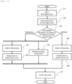
FIG. 3] FIG. 3 is a diagram showing an example of a processing flow according to Embodiment 2. - [
FIG. 4] FIG. 4 is a diagram showing an example of a processing flow according to Embodiment 3. - [
FIG. 5] FIG. 5 is a diagram showing an example of a processing flow according to Embodiment 4. - [
FIG. 6] FIG. 6 is a diagram showing an example of a setting screen according to Embodiment 5. - [
FIG. 7] FIG. 7 is a diagram showing a configuration example of an automatic analysis system according to Embodiment 6. - [
FIG. 8] FIG. 8 is a diagram showing an example of a processing flow according to Embodiment 6. - Hereinafter, embodiments of an automatic analysis system according to the invention will be described with reference to the accompanying drawings.
- A configuration example of an automatic analysis system according to
Embodiment 1 will be described with reference toFIG. 1 . The automatic analysis system includes acontrol unit 111, anautomatic analyzer 130, and aconveyance device 120 that are connected by acommunication cable 191. Amedical information system 101 may be connected to thecontrol unit 111 via anetwork communication 110. Hereinafter, the units will be described. - The
control unit 111 is a device that controls operations of theautomatic analyzer 130 and theconveyance device 120, and is implemented by, for example, a computer. Thecontrol unit 111 may control the operations of theautomatic analyzer 130 and theconveyance device 120 based on information transmitted from themedical information system 101. - The
automatic analyzer 130 is a device that automatically analyzes a specific component contained in a specimen such as blood or urine supplied from a patient, and includes ananalysis unit 131 and a specimenrack storage unit 132. Theanalysis unit 131 is a unit that executes analysis on the specimen. The specimenrack storage unit 132 storages aspecimen rack 190 on which a plurality of specimen tubes accommodating specimens are placed. Thespecimen rack 190 stored in the specimenrack storage unit 132 is a rack after being subjected to the analysis or a rack in which an error occurs. A barcode, an RFID, or the like is attached to at least one of the specimen tube and thespecimen rack 190 as an identifier for specifying the specimen. - The
conveyance device 120 includes a preprocessingunit 122 that performs a preprocess on thespecimen rack 190 input into aspecimen input port 121, and a specimenrack conveyance unit 192 that conveys thespecimen rack 190 after being subjected to the preprocess to theautomatic analyzer 130. The preprocess performed by the preprocessingunit 122 includes, for example, specimen classification, centrifugal separation, unplugging, aliquoting, label attachment, plugging, and storage. - The
medical information system 101 is a backbone system that handles medical information of the entire hospital, and includes aclinical examination system 102, a blood collectiontube preparation system 103, areservation system 104, and the like. Theclinical examination system 102 is a system that shares and manages examination request information, progress of examination results, outputs of examination results, and examination information for transmitting and receiving examination orders. Information such as an examination request registered in theclinical examination system 102 may be transmitted to thecontrol unit 111 and used to control the operations of theautomatic analyzer 130 and theconveyance device 120. Information input to the blood collectiontube preparation system 103 or thereservation system 104 may also be transmitted to thecontrol unit 111 and used to control the operations of theautomatic analyzer 130 and theconveyance device 120. - In the
automatic analyzer 130, a standby state and an operation state are selectively used. The standby state is a state in which although theautomatic analyzer 130 is energized, a mechanical system for operating an aliquoting probe, a reaction disk, and the like provided in theautomatic analyzer 130 is stopped. The operation state is a state in which the mechanical system operates and the specimen can be immediately analyzed. That is, when theautomatic analyzer 130 is in the standby state, the specimen cannot be analyzed until transitioning to the operation state is completed, and a time for an output of an examination result is required. - Therefore, in
Embodiment 1, the time required for the output of the examination result is shortened by starting to cause theautomatic analyzer 130 to transition from the standby state to the operation state at a timing when patient information of the specimen is registered in themedical information system 101. More specifically, thecontrol unit 111 to which the patient information registered in themedical information system 101 is transmitted starts to cause theautomatic analyzer 130 to transition from the standby state to the operation state, and the transitioning proceeds while thespecimen rack 190 is conveyed. The transitioning from the standby state to the operation state is started early, so that a time from reception of the specimen to the output of the examination result is shortened. - A timing when the
automatic analyzer 130 is caused to transition from the standby state to the operation state is not limited to the timing when the patient information is registered in themedical information system 101. For example, the transitioning of theautomatic analyzer 130 from the standby state to the operation state may be started at a timing when thespecimen rack 190 is input into thespecimen input port 121 of theconveyance device 120. More specifically, thecontrol unit 111 that receives the patient information associated with the identifier attached to thespecimen rack 190 input into thespecimen input port 121 starts to cause theautomatic analyzer 130 to transition from the standby state to the operation state, and the transitioning proceeds while thespecimen rack 190 is conveyed. The transitioning from the standby state to the operation state is started early, so that the time from the reception of the specimen to the output of the examination result is shortened. - A start operation, which is an operation of causing the
automatic analyzer 130 to transition from the standby state to the operation state, includes a reset operation and a confirmation operation. The reset operation is an operation of initializing theautomatic analyzer 130, and is an operation of returning the units to an initial position or discharging thespecimen rack 190 remaining in theautomatic analyzer 130. The confirmation operation is an operation of confirming that the mechanical system can be operated, and may include an operation of confirming that a liquid surface detection sensor provided in the aliquoting probe is normal. - Even when the
conveyance device 120 is in a standby state, thecontrol unit 111 may start to cause theconveyance device 120 to transition from the standby state to the operation state at the timing when the patient information is registered in themedical information system 101. In theconveyance device 120, the transitioning from the standby state to an operation state is also started early, thereby shortening the time. -
Embodiment 1 describes that thecontrol unit 111 that receives the patient information from themedical information system 101 or theconveyance device 120 causes theautomatic analyzer 130 to transition from the standby state to the operation state. Embodiment 2 describes that the preprocess is performed in theconveyance device 120 in parallel with the transitioning of theautomatic analyzer 130 from the standby state to the operation state. - A configuration example of an automatic analysis system according to Embodiment 2 will be described with reference to
FIG. 2 . As inEmbodiment 1, the automatic analysis system includes thecontrol unit 111, theautomatic analyzer 130, and theconveyance device 120 that are connected by thecommunication cable 191. Thecontrol unit 111 and theautomatic analyzer 130 have the same configurations as those ofEmbodiment 1, and thus description thereof will be omitted. - The
conveyance device 120 includes aninformation reading unit 201, thepreprocessing unit 122, and the specimenrack conveyance unit 192. Theinformation reading unit 201 is a device that reads an identifier attached to thespecimen rack 190 input into thespecimen input port 121, and is, for example, a barcode reader or an RFID reader. The identifier of thespecimen rack 190 is read immediately after thespecimen rack 190 is input into thespecimen input port 121. - The
preprocessing unit 122 is a unit that performs the preprocess on thespecimen rack 190 input into thespecimen input port 121, and includes at least one of acentrifugal separation unit 210, an unpluggingunit 211, analiquoting unit 212, alabel attaching unit 213, a pluggingunit 214, and astorage unit 215. - The
centrifugal separation unit 210 is a unit that performs the centrifugal separation on a specimen. The unpluggingunit 211 is a unit that opens a lid of the specimen tube accommodating a specimen. Thealiquoting unit 212 is a unit that aliquots the specimen accommodated in the specimen tube into other plurality of containers. An original specimen to be aliquoted is referred to as a parent specimen, and the specimen aliquoted into another container is referred to as a child specimen. Thelabel attaching unit 213 is a unit that attaches an identifier for identifying the child specimen to the container. The pluggingunit 214 is a unit that closes the lid of the specimen tube. Thestorage unit 215 is a unit that stores the specimen tube after being subjected to the analysis. These units may be provided in any order. - The specimen
rack conveyance unit 192 is a unit that conveys thespecimen rack 190 subjected to various preprocesses to theautomatic analyzer 130. - A processing flow executed in Embodiment 2 will be described step by step with reference to
FIG. 3 . - The
specimen rack 190 is input into thespecimen input port 121. - The
information reading unit 201 reads the identifier attached to thespecimen rack 190 immediately after being input into thespecimen input port 121, and transmits the read identifier to thecontrol unit 111. - The
control unit 111 determines presence or absence of a preprocessing operation for the specimen in thespecimen rack 190 based on the identifier transmitted from theinformation reading unit 201. When the preprocessing operation is present, the process proceeds to step 34 andstep 35, and when no preprocessing operation is present, the process proceeds to step 38. Thecontrol unit 111 receives the patient information associated with the identifier transmitted from theinformation reading unit 201. - The
control unit 111 causes thespecimen rack 190 to be conveyed to thepreprocessing unit 122, and causes the preprocessing operation to be performed on the specimen in thespecimen rack 190. - The
control unit 111 causes theautomatic analyzer 130 to execute the reset operation in parallel withstep 34. - After executing the reset operation in
step 35, theautomatic analyzer 130 transitions to the operation state by executing the confirmation operation, and is on standby until the preprocessing operation performed by thepreprocessing unit 122 is completed. - The
control unit 111 causes theautomatic analyzer 130 to transition to the operation state to start an analysis operation. - The
control unit 111 causes theautomatic analyzer 130 to execute the reset operation. - After executing the reset operation in
step 38, theautomatic analyzer 130 transitions to the operation state by executing the confirmation operation. - According to the processing flow described with reference to
FIG. 3 , thecontrol unit 111 starts to cause theautomatic analyzer 130 to transition from the standby state to the operation state at the timing when the patient information is received from theconveyance device 120. That is, as inEmbodiment 1, since the transitioning from the standby state to the operation state is started early, the time from the reception of the specimen to the output of the examination result is shortened. In parallel with the transitioning of theautomatic analyzer 130 from the standby state to the operation state, the preprocess is performed in theconveyance device 120, and thus the time from the reception of the specimen to the output of the examination result can be shortened. - Embodiment 2 describes that the preprocess is performed in the
conveyance device 120 in parallel with the transitioning of theautomatic analyzer 130 from the standby state to the operation state. Embodiment 3 describes that theautomatic analyzer 130 is caused to execute an additional maintenance process while the preprocess is performed in theconveyance device 120. - A processing flow executed in Embodiment 3 will be described with reference to
FIG. 4 . InFIG. 4 , steps 41 and 42 are added toFIG. 3 , and the description of steps other than these steps is omitted. - The
control unit 111 calculates a time required for the preprocessing operation instep 34 based on the identifier transmitted from theinformation reading unit 201, and determines whether an additional maintenance process can be executed. If the additional maintenance process can be executed, the process proceeds to step 42, and if the additional maintenance process cannot be executed, the process proceeds to step 35. Whether the additional maintenance process can be executed is determined based on a comparison between a time Tp required for the preprocessing operation and a time Tm required for the additional maintenance process. That is, if Tp > Tm, it is determined that the additional maintenance process can be executed. - The
control unit 111 causes theautomatic analyzer 130 to execute the additional maintenance process. The additional maintenance process may be a single process, a process of continuously repeating the single process a plurality of times, or a process of combining different processes. The execution of the additional maintenance process improves analysis accuracy of theautomatic analyzer 130. - As a specific example of the additional maintenance process, cleaning in a reagent flow path, a cell cleaning prime, and an air purge will be described. The cell cleaning prime and the air purge are maintenance processes having relatively short effective times.
- The cleaning in a reagent flow path is a maintenance process of replacing a reagent and the like remaining in a reagent flow path, and is performed a plurality of times when an elapsed time from when the
automatic analyzer 130 enters the standby state is long, for example, when the elapsed time is one hour or more. - The cell cleaning prime is a process of refilling a detergent in a flow path connected to a detergent probe that discharges the detergent to a container of a biological specimen reaction unit.
- The air purge is a process of replacing system water in a flow path connected to a reagent probe for suctioning a reagent with degassed water or removing bubbles in the flow path by continuously flowing pure water.
- According to the processing flow described with reference to
FIG. 4 , as inEmbodiment 1, the transitioning from the standby state to the operation state is started early, so that the time from the reception of the specimen to the output of the examination result is shortened. As in Embodiment 2, in parallel with the transitioning to the operation state, the preprocess is performed, and thus the time from the reception of the specimen to the output of the examination result can be shortened. Further, the analysis accuracy of theautomatic analyzer 130 can be improved by executing the additional maintenance process while the preprocess is performed. - Embodiment 2 describes that the
information reading unit 201 of theconveyance device 120 reads the identifier of thespecimen rack 190. When the identifier is read, some errors may occur. In Embodiment 4, a case will be described in which an error occurs at the time of reading the identifier. - A processing flow executed in Embodiment 4 will be described with reference to
FIG. 5 . InFIG. 5 ,step 32 inFIG. 4 is replaced withstep 51, steps 52 and 53 are added, and thus the description of steps other than these steps is omitted. - The
information reading unit 201 reads the identifier attached to thespecimen rack 190 immediately after being input into thespecimen input port 121, and transmits the read identifier to thecontrol unit 111. Thecontrol unit 111 determines whether the transmitted identifier is normal. If a determination result is normal, the process proceeds to step 33, and if an error is included, the process proceeds to step 52. The included error may be, for example, a reading error due to lack of information on the identifier, an error due to incorrect information, or an error due to an unanalyzable item request. - The
control unit 111 stores thespecimen rack 190 in the specimenrack storage unit 132. - After recovering the error by performing a handling process according to a type of the error, the
control unit 111 returns the process to step 31, and causes thespecimen rack 190 stored in the specimenrack storage unit 132 to be input again. - According to the processing flow described with reference to
FIG. 5 , as inEmbodiment 1, the transitioning from the standby state to the operation state is started early, so that the time from the reception of the specimen to the output of the examination result is shortened. As in Embodiment 2, in parallel with the transitioning to the operation state, the preprocess is performed, and thus the time from the reception of the specimen to the output of the examination result can be shortened. As in Embodiment 3, since the additional maintenance process is executed while the preprocess is performed, the analysis accuracy of theautomatic analyzer 130 can be improved. Further, when an error occurs at the time of reading the identifier, theautomatic analyzer 130 is maintained in the standby state, thespecimen rack 190 is input again after the error is recovered, and thus it is possible to avoid a failure due to the error. -
Embodiment 1 describes that thecontrol unit 111 that receives the patient information from themedical information system 101 or theconveyance device 120 causes theautomatic analyzer 130 to transition from the standby state to the operation state. Theautomatic analyzer 130 that transitions to the operation state repeatedly performs a cleaning operation until thespecimen rack 190 arrives, and thus when it takes a long time for the arrival of thespecimen rack 190, resources such as water and detergent used for the cleaning operation are wasted. Embodiment 6 describes that whether to cause theautomatic analyzer 130 to transition to the operation state or to transition to a preparation state for preventing the waste of the resources is selected according to an arrival time of thespecimen rack 190. The preparation state is a state in which the mechanical system for operating the aliquoting probe, the reaction disk, and the like provided in theautomatic analyzer 130 operates and the specimen can be immediately analyzed, but the cleaning operation is not performed. That is, the resources are saved in the preparation state as compared with the operation state. - An example of a setting screen used in Embodiment 5 will be described with reference to
FIG. 6 . Asetting screen 601 shown inFIG. 6 is a screen for setting a determination time, and includes aninput area 602, aregistration button 603, and aclose button 604. The determination time is input to theinput area 602. When the determination time input to theinput area 602 is to be registered, theregistration button 603 is pressed. When thesetting screen 601 is to be closed, theclose button 604 is pressed. - The determination time set on the
setting screen 601 is used when thecontrol unit 111 that receives the patient information from themedical information system 101 or theconveyance device 120 determines which of the operation state and the preparation state is to be selected. That is, a time Ta until thespecimen rack 190 arrives at theautomatic analyzer 130 is compared with a determination time Tj. If Ta < Tj, the operation state is selected, and if Ta ≥ Tj, the preparation state is selected. Theautomatic analyzer 130 in the preparation state transitions to the operation state when thespecimen rack 190 arrives. - According to Embodiment 5, when the time Ta from the reception of the patient information by the
control unit 111 to the arrival of thespecimen rack 190 at theautomatic analyzer 130 is equal to or longer than the determination time Tj, theautomatic analyzer 130 transitions to the preparation state, and thus the resources such as water and detergent used for the cleaning operation can be saved. The preparation state may be implemented by performing the cleaning operation without using the detergent and saving the detergent. -
Embodiments 1 to 5 describe the case in which thespecimen rack 190 is input to the singlespecimen input port 121. Embodiment 6 describes a case in which thespecimen rack 190 is input to a plurality of specimen input ports. - A configuration example of the
conveyance device 120 according to Embodiment 6 will be described with reference toFIG. 7 . Theconveyance device 120 according to Embodiment 6 includes thecentrifugal separation unit 210 and the unpluggingunit 211. - The
centrifugal separation unit 210 includes a centrifugalseparation input port 710, abuffer 711, and acentrifuge unit 712. The specimen rack is input into the centrifugalseparation input port 710. The specimen rack input into the centrifugalseparation input port 710 is classified into a centrifugal requiredrack 701 which is a specimen rack requiring the centrifugal separation and a centrifugalunrequired rack 702 which is a specimen rack not requiring the centrifugal separation based on the identifier read by theinformation reading unit 201. The centrifugal requiredrack 701 is placed in thebuffer 711, and the centrifugalunrequired rack 702 is moved to aspecimen conveyance line 703. Thebuffer 711 accumulates a certain number of the centrifugal requiredracks 701, and sends the centrifugal requiredracks 701 to thecentrifuge unit 712 in an accumulation order. In thecentrifuge unit 712, the specimen in the centrifugal requiredrack 701 sent from thebuffer 711 is subjected to the centrifugal separation. - The unplugging
unit 211 includes an unplugginginput port 720 and an unpluggingportion 721. The specimen rack is input into the unplugginginput port 720, and the lid of the specimen tube placed on the specimen rack is opened in the unpluggingportion 721. That is, theconveyance device 120 according to Embodiment 6 includes the centrifugalseparation input port 710 and the unplugginginput port 720 as the plurality of specimen input ports. - When the
buffer 711 is filled with the centrifugal requiredracks 701 and the centrifugal requiredrack 701 also stays in the centrifugalseparation input port 710, the input centrifugalunrequired rack 702 stagnates in the centrifugalseparation input port 710 and reaches theautomatic analyzer 130 with a delay, and thus the output of the examination result is delayed. - Therefore, in Embodiment 6, a time until the examination result is output is shortened by selectively using the plurality of specimen input ports. More specifically, by inputting the centrifugal required
rack 701 into the centrifugalseparation input port 710 and inputting the centrifugalunrequired rack 702 into the unplugginginput port 720, stagnation of the centrifugalunrequired rack 702 is prevented and the output of the examination result of the specimen is not delayed. Arrangement positions of the centrifugalseparation input port 710 and the unplugginginput port 720 are not limited to the positions shown inFIG. 7 , and may be any positions as long as the positions are upstream of the corresponding preprocessing units. For example, the arrangement position of the unplugginginput port 720 may be between the centrifugalseparation input port 710 and thecentrifuge unit 712 or on a left side of the centrifugalseparation input port 710. - A processing flow executed in Embodiment 6 will be described with reference to
FIG. 8 . InFIG. 8 ,step 33,step 38, and step 39 are deleted fromFIG. 5 , and step 34 is replaced withstep 81 to step 87, and thus the description of steps other thansteps 81 to 87 is omitted. - The
control unit 111 determines a content of the preprocess based on the identifier transmitted from theinformation reading unit 201. When the content of the preprocess includes neither the centrifugal separation nor the unplugging, the process proceeds to step 37. That is, the specimen rack is directly conveyed to theautomatic analyzer 130. When the content of the preprocess does not include the centrifugal separation and includes the unplugging, the process proceeds to step 82, and when the content of the preprocess includes both the centrifugal separation and the unplugging, the process proceeds to step 83. - The
control unit 111 determines the position where the specimen rack is input. When the specimen rack is input into the centrifugalseparation input port 710, the process proceeds to step 86, and when the specimen rack is input into the unplugginginput port 720, the process proceeds to step 87. - The
control unit 111 determines the position where the specimen rack is input. When the specimen rack is input into the centrifugalseparation input port 710, the process proceeds to step 84. When the specimen rack is input into the unplugginginput port 720, the centrifugal separation cannot be performed, and thus the process proceeds to step 52 assuming that an error occurs. - The
control unit 111 causes the specimen rack to be conveyed to thecentrifuge unit 712. - The
centrifuge unit 712 executes the centrifugal separation on the specimen in the conveyed specimen rack. - The
control unit 111 causes the specimen rack after being subjected to the centrifugal separation to be conveyed to the unpluggingportion 721. - The unplugging
portion 721 unplugs the specimen tube mounted on the conveyed specimen rack, and conveys the specimen rack after being unplugged to theautomatic analyzer 130. - According to the processing flow described with reference to
FIG. 8 , as inEmbodiment 1, the transitioning from the standby state to the operation state is started early, so that the time from the reception of the specimen to the output of the examination result is shortened. As in Embodiment 2, in parallel with the transitioning to the operation state, the preprocess is performed, and thus the time from the reception of the specimen to the output of the examination result can be shortened. As in Embodiment 3, since the additional maintenance process is executed while the preprocess is performed, the analysis accuracy of theautomatic analyzer 130 can be improved. As in Embodiment 4, when an error occurs at the time of reading the identifier, theautomatic analyzer 130 is maintained in the standby state, thespecimen rack 190 is input again after the error is recovered, and thus it is possible to avoid the failure due to the error. - Further, since the plurality of specimen input ports are selectively used, the centrifugal
unrequired rack 702 does not stagnate in the centrifugalseparation input port 710, and a delayed output of the examination result can be prevented. A conveyance destination of the specimen rack is determined based on the content of the preprocess and the position where the specimen rack is input, and thus an appropriate preprocess is performed on the specimen. For example, when the centrifugal requiredrack 701 is erroneously input into the unplugginginput port 720, it is considered that an error occurs, and thus it is possible to avoid a failure due to the preprocess. - The embodiments of the invention have been described above. The invention is not limited to the above-described embodiments, and the components may be modified without departing from the gist of the invention. The plurality of components disclosed in the above embodiments may be combined as appropriate. Further, some components may be deleted from all the components shown in the above embodiments.
-
- 101:
- medical information system
- 102:
- clinical examination system
- 103:
- blood collection tube preparation system
- 104:
- reservation system
- 110:
- network communication
- 111:
- control unit
- 120:
- conveyance device
- 121:
- specimen input port
- 122:
- preprocessing unit
- 130:
- automatic analyzer
- 131:
- analysis unit
- 132:
- specimen rack storage unit
- 190:
- specimen rack
- 191:
- communication cable
- 192:
- specimen rack conveyance unit
- 201:
- information reading unit
- 210:
- centrifugal separation unit
- 211:
- unplugging unit
- 212:
- aliquoting unit
- 213:
- label attaching unit
- 214:
- plugging unit
- 215:
- storage unit
- 601:
- setting screen
- 602:
- input area
- 603:
- registration button
- 604:
- close button
- 701:
- centrifugal required rack
- 702:
- centrifugal unrequired rack
- 703:
- specimen conveyance line
- 710:
- centrifugal separation input port
- 711:
- buffer
- 712:
- centrifuge unit
- 720:
- unplugging input port
- 721:
- unplugging portion
Claims (7)
- An automatic analysis system comprising:an automatic analyzer configured to analyze a specimen of a patient;a conveyance device configured to convey the specimen to the automatic analyzer; anda control unit configured to control the automatic analyzer and the conveyance device, whereinwhen information on the patient is received from a medical information system or the conveyance device, the control unit causes the automatic analyzer to transition from a standby state to an operation state.
- The automatic analysis system according to claim 1, wherein
when the information on the patient is received from the medical information system, the control unit causes the conveyance device to transition from a standby state to an operation state. - The automatic analysis system according to claim 1, wherein
the control unit causes the conveyance device to perform a preprocess on the specimen in parallel with the transitioning of the automatic analyzer to the operation state. - The automatic analysis system according to claim 3, wherein
when the conveyance device performs the preprocess, the control unit causes the automatic analyzer to execute an additional maintenance process. - The automatic analysis system according to claim 1, whereinthe conveyance device includes an information reading unit configured to read an identifier of the specimen, andwhen the identifier read by the information reading unit includes an error, the control unit stores the specimen and maintains the automatic analyzer in the standby state.
- The automatic analysis system according to claim 1, wherein
when a time from the reception of the information on the patient to arrival of the specimen at the automatic analyzer is a predetermined time or longer, the control unit causes the automatic analyzer to transition to a preparation state in which a resource is saved as compared with the operation state. - The automatic analysis system according to claim 1, whereinthe conveyance device has a plurality of input ports into which the specimen is input, andthe control unit determines a conveyance destination of the specimen based on a content of a preprocess performed on the specimen and a position of the input port into which the specimen is input.
Applications Claiming Priority (2)
| Application Number | Priority Date | Filing Date | Title |
|---|---|---|---|
| JP2022045592 | 2022-03-22 | ||
| PCT/JP2022/045133 WO2023181515A1 (en) | 2022-03-22 | 2022-12-07 | Automatic analysis system |
Publications (2)
| Publication Number | Publication Date |
|---|---|
| EP4498089A1 true EP4498089A1 (en) | 2025-01-29 |
| EP4498089A4 EP4498089A4 (en) | 2026-06-03 |
Family
ID=88100478
Family Applications (1)
| Application Number | Title | Priority Date | Filing Date |
|---|---|---|---|
| EP22932497.5A Pending EP4498089A4 (en) | 2022-03-22 | 2022-12-07 | AUTOMATIC ANALYSIS SYSTEM |
Country Status (5)
| Country | Link |
|---|---|
| US (1) | US20250138038A1 (en) |
| EP (1) | EP4498089A4 (en) |
| JP (1) | JPWO2023181515A1 (en) |
| CN (1) | CN118871787A (en) |
| WO (1) | WO2023181515A1 (en) |
Family Cites Families (9)
| Publication number | Priority date | Publication date | Assignee | Title |
|---|---|---|---|---|
| JPH11304812A (en) * | 1998-04-20 | 1999-11-05 | Hitachi Ltd | Sample processing system |
| JP2003121449A (en) * | 2001-10-12 | 2003-04-23 | Hitachi High-Technologies Corp | Sample analysis system |
| JP5778887B2 (en) * | 2009-05-29 | 2015-09-16 | シスメックス株式会社 | Sample processing equipment |
| JP5308952B2 (en) * | 2009-07-27 | 2013-10-09 | 株式会社日立ハイテクノロジーズ | Automatic analyzer |
| JP6047399B2 (en) * | 2012-12-28 | 2016-12-21 | 株式会社日立ハイテクノロジーズ | Sample transport system in automatic analyzer |
| JP6274398B2 (en) * | 2013-11-25 | 2018-02-07 | キヤノンメディカルシステムズ株式会社 | Automatic analyzer |
| JP6247935B2 (en) * | 2014-01-07 | 2017-12-13 | 株式会社日立ハイテクノロジーズ | Automatic analyzer |
| JP6719227B2 (en) * | 2016-02-19 | 2020-07-08 | 株式会社日立ハイテク | Automatic analyzer |
| EP3640646A1 (en) * | 2018-10-16 | 2020-04-22 | F. Hoffmann-La Roche AG | Method of operating an analytical laboratory |
-
2022
- 2022-12-07 US US18/837,212 patent/US20250138038A1/en active Pending
- 2022-12-07 EP EP22932497.5A patent/EP4498089A4/en active Pending
- 2022-12-07 CN CN202280093139.8A patent/CN118871787A/en active Pending
- 2022-12-07 WO PCT/JP2022/045133 patent/WO2023181515A1/en not_active Ceased
- 2022-12-07 JP JP2024509752A patent/JPWO2023181515A1/ja active Pending
Also Published As
| Publication number | Publication date |
|---|---|
| CN118871787A (en) | 2024-10-29 |
| US20250138038A1 (en) | 2025-05-01 |
| WO2023181515A1 (en) | 2023-09-28 |
| EP4498089A4 (en) | 2026-06-03 |
| JPWO2023181515A1 (en) | 2023-09-28 |
Similar Documents
| Publication | Publication Date | Title |
|---|---|---|
| US11199559B2 (en) | Automatic analyzer | |
| JP6307446B2 (en) | Centrifuge system, specimen pretreatment system, and control method | |
| JP5142976B2 (en) | Automatic analyzer | |
| JP6018406B2 (en) | Operation method of automatic sample work cell | |
| EP3176587B1 (en) | Automated analyzer | |
| JP5331056B2 (en) | Automatic analyzer | |
| JP2008209338A (en) | Automatic analyzer | |
| WO2013180017A1 (en) | Centrifugal separator, processing system provided with centrifugal separator, and method for controlling said system | |
| CN112798800A (en) | Sample analysis system and sample planning method thereof | |
| WO2021153028A1 (en) | Automatic analysis system | |
| JP6943977B2 (en) | Automatic analyzer | |
| JP6499872B2 (en) | Specimen transfer device and specimen transport system | |
| CN112578139B (en) | Sample testing method, sample analyzer and storage medium | |
| JPS60114768A (en) | Fully automatic blood analyzer | |
| US20250138038A1 (en) | Automatic analysis system | |
| JP5308952B2 (en) | Automatic analyzer | |
| JPH11304806A (en) | Sample test preprocessing automation system | |
| CN114636830A (en) | Sample analysis apparatus, system and test method thereof | |
| JP5000945B2 (en) | Sample transport system | |
| EP4737905A1 (en) | Specimen processing device and specimen processing method | |
| JP2009294230A (en) | Automatic analyzer | |
| CN114646766A (en) | Sample analysis system, scheduling system, and sample analysis method | |
| JP7603752B2 (en) | Processing test samples in a laboratory environment | |
| JP5638024B2 (en) | Sample transport system | |
| CN119224346A (en) | Sample inspection system and sample channel configuration method |
Legal Events
| Date | Code | Title | Description |
|---|---|---|---|
| STAA | Information on the status of an ep patent application or granted ep patent |
Free format text: STATUS: THE INTERNATIONAL PUBLICATION HAS BEEN MADE |
|
| PUAI | Public reference made under article 153(3) epc to a published international application that has entered the european phase |
Free format text: ORIGINAL CODE: 0009012 |
|
| STAA | Information on the status of an ep patent application or granted ep patent |
Free format text: STATUS: REQUEST FOR EXAMINATION WAS MADE |
|
| 17P | Request for examination filed |
Effective date: 20241022 |
|
| AK | Designated contracting states |
Kind code of ref document: A1 Designated state(s): AL AT BE BG CH CY CZ DE DK EE ES FI FR GB GR HR HU IE IS IT LI LT LU LV MC ME MK MT NL NO PL PT RO RS SE SI SK SM TR |
|
| DAV | Request for validation of the european patent (deleted) | ||
| DAX | Request for extension of the european patent (deleted) | ||
| RIC1 | Information provided on ipc code assigned before grant |
Ipc: G01N 35/00 20060101AFI20260209BHEP Ipc: G01N 35/02 20060101ALI20260209BHEP |
|
| A4 | Supplementary search report drawn up and despatched |
Effective date: 20260506 |
|
| RIC1 | Information provided on ipc code assigned before grant |
Ipc: G01N 35/00 20060101AFI20260428BHEP Ipc: G01N 35/02 20060101ALI20260428BHEP |