EP4498029A1 - Plate heat exchanger with improved fluid leakage detection system - Google Patents
Plate heat exchanger with improved fluid leakage detection system Download PDFInfo
- Publication number
- EP4498029A1 EP4498029A1 EP23425038.9A EP23425038A EP4498029A1 EP 4498029 A1 EP4498029 A1 EP 4498029A1 EP 23425038 A EP23425038 A EP 23425038A EP 4498029 A1 EP4498029 A1 EP 4498029A1
- Authority
- EP
- European Patent Office
- Prior art keywords
- heat exchanger
- channels
- plate
- plate heat
- fluid
- Prior art date
- Legal status (The legal status is an assumption and is not a legal conclusion. Google has not performed a legal analysis and makes no representation as to the accuracy of the status listed.)
- Pending
Links
Images


Classifications
-
- F—MECHANICAL ENGINEERING; LIGHTING; HEATING; WEAPONS; BLASTING
- F28—HEAT EXCHANGE IN GENERAL
- F28D—HEAT-EXCHANGE APPARATUS, NOT PROVIDED FOR IN ANOTHER SUBCLASS, IN WHICH THE HEAT-EXCHANGE MEDIA DO NOT COME INTO DIRECT CONTACT
- F28D9/00—Heat-exchange apparatus having stationary plate-like or laminated conduit assemblies for both heat-exchange media, the media being in contact with different sides of a conduit wall
- F28D9/0031—Heat-exchange apparatus having stationary plate-like or laminated conduit assemblies for both heat-exchange media, the media being in contact with different sides of a conduit wall the conduits for one heat-exchange medium being formed by paired plates touching each other
- F28D9/0037—Heat-exchange apparatus having stationary plate-like or laminated conduit assemblies for both heat-exchange media, the media being in contact with different sides of a conduit wall the conduits for one heat-exchange medium being formed by paired plates touching each other the conduits for the other heat-exchange medium also being formed by paired plates touching each other
-
- F—MECHANICAL ENGINEERING; LIGHTING; HEATING; WEAPONS; BLASTING
- F28—HEAT EXCHANGE IN GENERAL
- F28D—HEAT-EXCHANGE APPARATUS, NOT PROVIDED FOR IN ANOTHER SUBCLASS, IN WHICH THE HEAT-EXCHANGE MEDIA DO NOT COME INTO DIRECT CONTACT
- F28D9/00—Heat-exchange apparatus having stationary plate-like or laminated conduit assemblies for both heat-exchange media, the media being in contact with different sides of a conduit wall
- F28D9/0031—Heat-exchange apparatus having stationary plate-like or laminated conduit assemblies for both heat-exchange media, the media being in contact with different sides of a conduit wall the conduits for one heat-exchange medium being formed by paired plates touching each other
- F28D9/0043—Heat-exchange apparatus having stationary plate-like or laminated conduit assemblies for both heat-exchange media, the media being in contact with different sides of a conduit wall the conduits for one heat-exchange medium being formed by paired plates touching each other the plates having openings therein for circulation of at least one heat-exchange medium from one conduit to another
- F28D9/005—Heat-exchange apparatus having stationary plate-like or laminated conduit assemblies for both heat-exchange media, the media being in contact with different sides of a conduit wall the conduits for one heat-exchange medium being formed by paired plates touching each other the plates having openings therein for circulation of at least one heat-exchange medium from one conduit to another the plates having openings therein for both heat-exchange media
-
- F—MECHANICAL ENGINEERING; LIGHTING; HEATING; WEAPONS; BLASTING
- F28—HEAT EXCHANGE IN GENERAL
- F28D—HEAT-EXCHANGE APPARATUS, NOT PROVIDED FOR IN ANOTHER SUBCLASS, IN WHICH THE HEAT-EXCHANGE MEDIA DO NOT COME INTO DIRECT CONTACT
- F28D20/00—Heat storage plants or apparatus in general; Regenerative heat-exchange apparatus not covered by groups F28D17/00 or F28D19/00
- F28D20/02—Heat storage plants or apparatus in general; Regenerative heat-exchange apparatus not covered by groups F28D17/00 or F28D19/00 using latent heat
- F28D20/021—Heat storage plants or apparatus in general; Regenerative heat-exchange apparatus not covered by groups F28D17/00 or F28D19/00 using latent heat the latent heat storage material and the heat-exchanging means being enclosed in one container
-
- F—MECHANICAL ENGINEERING; LIGHTING; HEATING; WEAPONS; BLASTING
- F28—HEAT EXCHANGE IN GENERAL
- F28F—DETAILS OF HEAT-EXCHANGE AND HEAT-TRANSFER APPARATUS, OF GENERAL APPLICATION
- F28F1/00—Tubular elements; Assemblies of tubular elements
- F28F1/003—Multiple wall conduits, e.g. for leak detection
-
- F—MECHANICAL ENGINEERING; LIGHTING; HEATING; WEAPONS; BLASTING
- F28—HEAT EXCHANGE IN GENERAL
- F28F—DETAILS OF HEAT-EXCHANGE AND HEAT-TRANSFER APPARATUS, OF GENERAL APPLICATION
- F28F2265/00—Safety or protection arrangements; Arrangements for preventing malfunction
- F28F2265/16—Safety or protection arrangements; Arrangements for preventing malfunction for preventing leakage
-
- F—MECHANICAL ENGINEERING; LIGHTING; HEATING; WEAPONS; BLASTING
- F28—HEAT EXCHANGE IN GENERAL
- F28F—DETAILS OF HEAT-EXCHANGE AND HEAT-TRANSFER APPARATUS, OF GENERAL APPLICATION
- F28F2270/00—Thermal insulation; Thermal decoupling
- F28F2270/02—Thermal insulation; Thermal decoupling by using blind conduits
Definitions
- the present invention refers in general to a plate heat exchanger and, more specifically, to a brazed plate heat exchanger or a fusion-bonded plate heat exchanger provided with an improved system for detecting leakage of at least one of the two fluids flowing inside the heat exchanger.
- Heat exchangers are devices used to transfer heat between two or more fluids.
- a plate heat exchanger is a specific type of heat exchanger wherein metal plates are used to transfer heat between two fluids.
- Plate-type heat exchangers generally comprise a start plate, an end plate and a plurality of intermediate plates stacked onto one another, so as to form flow channels between them.
- the two fluids at different temperatures one of which is usually identified as the refrigerant fluid
- the two fluids at different temperatures respectively flow through plate channels obtained between opposite surfaces of pairs of adjacent heat exchanger plates: in this way the two fluids exchange their thermal content.
- These fluids can flow counter-current or co-current and their leak-free circulation is ensured by gaskets or by the junctions between the heat exchanger plates.
- the flow channels between the heat exchanger plates are commonly obtained by providing both plate surfaces with a corrugated pattern.
- both plate surfaces are provided with a pressed pattern of ridges and grooves.
- a common way of manufacturing a plate-type heat exchanger is to braze the heat exchanger plates together. This way of manufacturing requires that the heat exchanger plates are provided with a brazing material. During manufacturing, the heat exchanger plates stacked onto one another and placed in a furnace having a temperature sufficiently hot to at least partially melt the brazing material. After the temperature of the furnace has been lowered, the brazing material will solidify, allowing the heat exchanger plates to become joined to one another to form a compact and strong heat exchanger.
- Another way of manufacturing a plate-type heat exchanger is to join together the heat exchanger plates by a special fusion bonding technology.
- Fusion-bonded plate heat exchangers are manufactured using a 100% stainless steel construction. Fusion-bonded plate heat exchangers are designed to operate under higher pressures and temperatures than standard brazed plate heat exchangers. The manufacture of fusion-bonded plate heat exchangers does not require gaskets, making these plate-type heat exchangers ideal for applications where aggressive process fluids or other conditions could damage the gaskets traditionally used in gasketed plate-type heat exchangers.
- Present design of mixing proof in a plate heat exchanger typically involves intermediate empty separation channels between the adjacent channels of the two fluid circuits. These separation channels are connected one by one to the external environment by a plurality of drain nozzles, holes, or openings, from which any fluid leakage can spill into the surrounding environment.
- a first drawback is due to the fact that the detection of the fluid leakage can occur after some time, when most of the fluid has been lost. Additionally, leaking fluid can end into unwanted spaces of the channels, creating potential unhealthy or dangerous conditions in the plate heat exchanger. Furthermore, fluid leakage cannot be temporarily stopped, while waiting for repair of the plate heat exchanger, when some of the fluid(s) could be recovered.
- each heat transfer plate is provided with two drain holes, i.e., an upper drain hole and a lower drain hole.
- the plate heat exchanger includes leak passageways which channel internal leaks, that may occur within the plate heat exchanger, to the upper and lower drain holes.
- One object of the present invention is therefore to provide a plate heat exchanger which is capable of resolving the drawbacks of the prior art in a simple, inexpensive and particularly functional manner.
- one object of the present invention is to provide a plate heat exchanger wherein the leakage detection of the fluids flowing into the exchanger can take place in the shortest possible time, so that the loss of these fluids is also reduced as much as possible.
- Another object of the present invention is to provide a plate heat exchanger wherein the leaking fluids cannot flow into unwanted spaces, thereby avoiding potential unhealthy or dangerous conditions.
- a further object of the present invention is to provide a plate heat exchanger wherein the fluid leakage can be stopped easily and quickly while waiting for repair work, when some fluid could be recovered.
- the plate heat exchanger according to the present invention comprises a plurality of heat exchanger plates which are stacked onto one another.
- the heat exchanger plates are obtained by forming from respective metal sheets and are permanently joined to each other through a joining technology of metallic materials, so as to form a plate package provided with first plate interspaces, which form respective first channels of a first circulation circuit for a first fluid, second plate interspaces, which form respective second channels of a second circulation circuit for a second fluid, and third plate interspaces, which form respective separation channels between the first channels and the second channels.
- the separation channels are arranged adjacent to both the first channels and the second channels.
- Each heat exchanger plate is provided with a plurality of portholes which communicates with the first channels and the second channels.
- Each heat exchanger plate is provided with one or more side edges which form the outer perimeter of the heat exchanger plates.
- a single outlet fluid collector is arranged on one of the side edges.
- the separation channels are sealed with respect to the first channels, the second channels and the side edges.
- the separation channels are in fluid communication with the single outlet fluid collector only.
- a single drain nozzle is provided on the single outlet fluid collector for the discharge to the external environment of any fluids flowing into the separation channels and through the single outlet fluid collector.
- the heat exchanger plates are of rectangular shape, with a first pair of side edges parallel to each other and a second pair of side edges parallel to each other and perpendicular to the first pair of side edges.
- the separation channels are also parallel to each other, and the single outlet fluid collector consists of an elongated channel which is arranged on one of the edges of either the first pair of side edges or the second pair of side edges and arranged perpendicular to the separation channels.
- the separation channels are empty under normal operating conditions of the plate heat exchanger.
- the separation channels are filled with a liquid which is still under normal operating conditions of the plate heat exchanger.
- This liquid is capable of enhancing the heat transfer between the first fluid and the second fluid.
- the liquid is filled with additional substances. More preferably, these additional substances are chosen from the group consisting of:
- the drain nozzle is provided with sensor means for detecting the leakage of fluids through the drain nozzle. More preferably, the sensor means comprise one single gas detector, or one single liquid level probe, or one single pressure switch.
- At least one piping is connected downstream of the drain nozzle. This piping is arranged to transport outside the plate heat exchanger the fluid discharged from the drain nozzle.
- At least one plug is tightly and removably engaged with the drain nozzle.
- the drain nozzle and the plug are provided with respective threaded connections having the same pitch, to obtain a threaded screw-to-nut coupling between the plug and the drain nozzle.
- the heat exchanger 10 comprises, in a per se known manner, a plurality of heat exchanger plates 12A, 12B stacked onto one another.
- the heat exchanger plates 12A, 12B are stacked onto one another between a first end plate 14 and a second end plate 16 of the heat exchanger 10.
- the first end plate 14 and the second end plate 16 form the front and rear end plates of the heat exchanger 10, respectively.
- These front and rear end plates are also called “frame plate” and "pressure plate”.
- the purpose of these front and rear end plates is to mechanically strengthen the heat exchanger 10, as well as to provide a support for the fluid connections of the heat exchanger 10.
- Each heat exchanger plate 12A, 12B, 14, 16 is obtained by forming from a respective metal sheet.
- the first end plate 14, the second end plate 16 and the heat exchanger plates 12A, 12B are permanently joined to each other through a joining technology of metallic materials, so as to form a plate package 30.
- this joining technology can be a brazing technology by means of a braze material, a fusion bonding technology or any other technology known in the technical field of the plate heat exchangers.
- the plate package 30 is thus provided (see for example Figures 3-5 ) with first plate interspaces, which form respective first channels 32 of a first circulation circuit for a first fluid, and second plate interspaces, which form respective second channels 32 of a second circulation circuit for a second fluid.
- the first fluid and the second fluid may be any suitable heat transfer fluid.
- the first fluid can be the hotter fluid and the second fluid can be the colder fluid.
- the second fluid is therefore the cooling fluid, and it receives the heat from the first fluid.
- Each heat exchanger plate 12A, 12B, as well as the first end plate 14 and the second end plate 16, is provided with a plurality of portholes, preferably four portholes P1, P2, P3 and P4.
- a first porthole P1 is connected to a first connection pipe 18 and communicates with the first channels 32.
- a second porthole P2 is connected to a second connection pipe 20 and communicates with the first channels 32.
- a third porthole P3 is connected to a third connection pipe 22 and communicates with the second channels 34.
- a fourth porthole P4 is connected to a fourth connection pipe 24 and communicates with the second channels 34.
- Connection pipes 18, 20, 22 and 24 may be provided extending from the first end plate 14, as shown in Figure 1 , and/or from the second end plate 16.
- Each heat exchanger plate 12A, 12B, as well as the first end plate 14 and the second end plate 16 can have the shape of any plane figure bounded by a closed line, such as a convex polygon or even a circle.
- Each heat exchanger plate 12A, 12B, as well as the first end plate 14 and the second end plate 16, is thus provided with one or more side edges 26, 28, which form the outer perimeter of the heat exchanger plates 12A, 12B, 14, 16.
- the plate package 30 is also provided (see again Figures 3-5 ) with third plate interspaces, which form respective separation channels 36 between the first channels 32 for the first fluid and the second channels 34 for the second fluid.
- the separation channels 36 are arranged adjacent to both the first channels 32 and the second channels 34.
- a single outlet fluid collector 38 is arranged on one of the side edges 26, 28 of the heat exchanger plates 12A, 12B, 14, 16. All the separation channels 36 are sealed with respect to the first channels 32, the second channels 34 and the side edges 26, 28 of the heat exchanger plates 12A, 12B, 14, 16, but all these separation channels 36 are in fluid communication with the single outlet fluid collector 38.
- a single drain nozzle 40 is thus provided on the single outlet fluid collector 38 for the discharge to the external environment of any fluids flowing into the separation channels 36 and through the single outlet fluid collector 38.
- the leaking first fluid and/or second fluid goes into the separation channels 36, since these separation channels 36 are immediately adjacent to the first channels 32 and the second channels 34.
- the leaking fluid therefore, has no other exit pathways other than the single outlet fluid collector 38 and the single drain nozzle 40 located downstream of the latter. Consequently, the leaking fluid can be easily and quickly detected at the single drain nozzle 40.
- each heat exchanger plate 12A, 12B, as well as the first end plate 14 and the second end plate 16 has a substantially rectangular shape, with a first pair of side edges 26 (e.g., the long side edges) parallel to each other and a second pair of side edges 28 (e.g., the short side edges) also parallel to each other and perpendicular to the first pair of side edges 26.
- a longitudinal axis X extends parallel to the two long side edges 26 and transversely to the two short side edges 28.
- the separation channels 36 are also parallel to each other, whereas the single outlet fluid collector 38 consists of an elongated channel which is arranged on one of the edges of either the first pair of side edges 26 or the second pair of side edges 28.
- the single outlet fluid collector 38 is thus arranged perpendicular to the separation channels 36. This preferred linear arrangement of the separation channels 36 and the outlet fluid collector 38 is made to avoid traps or sealed barriers that could prevent the leaking fluid from reaching the drain nozzle 40.
- the separation channels 36 are empty under normal operating conditions of the heat exchanger 10.
- the separation channels 36 are filled with ambient air and no fluid normally circulates in these separation channels 36 unless a breakage in the first channels 32 of the first circulation circuit and/or the second channels 34 of the second circulation circuit occur.
- the separation channels 36 are filled with a liquid L which is still under normal operating conditions of the plate heat exchanger 10.
- the still liquid L that is, a liquid that does not normally move within the separation channels 36, can be any liquid suitable for enhancing the heat transfer between the first fluid and the second fluid, compared with the case where the separation channels 36 are filled with ambient air.
- the circuit formed by the separation channels 36 can be provided with at least one small openable port (not shown), which is normally sealingly closed, and which is designed to facilitate the filling and/or refilling of the liquid L contained in these separation channels 36.
- the heat exchanger 10 could be designed for an easy draining, filling, refilling, changing, or restoring of this liquid L during or after positioning/assembling, as well as during ordinary maintenance.
- the drain nozzle 40 In case of pre-filling, the drain nozzle 40 must be closed to avoid liquid spilling out during transportation and during handling or installation of the heat exchanger 10.
- the liquid L must be suitable for working conditions and safety and environmental standards.
- the liquid L can be filled with additional substances.
- these additional substances can be chosen from the group consisting of:
- the drain nozzle 40 can be provided with sensor means 42 for detecting the leakage of fluids through the drain nozzle 40.
- these sensor means 42 may include, but not be limited to, one single gas detector, one single liquid level probe or one single pressure switch.
- the leaking first fluid and/or second fluid is forced to flow through the single drain nozzle 40, where its presence can be easily detected with one single sensor means 42.
- At least one piping 44 can be connected downstream of the drain nozzle 40.
- the piping 44 is arranged to transport outside the plate heat exchanger 10 the fluid discharged from the drain nozzle 40.
- a safe place e.g., outdoor ambient
- At least one plug 46 can be tightly and removably engaged with the drain nozzle 40.
- the drain nozzle 40 and the plug 46 can be provided with respective threaded connections having the same pitch, to obtain a threaded screw-to-nut coupling between the plug 46 and the drain nozzle 40.
- the plug 46 in case of leakage of the first fluid and/or the second fluid, the drain nozzle 40 can be temporarily plugged, thus stopping the release of the fluid to the environment. This can prevent the release of the fluid to the environment while waiting for the fixing of the heat exchanger 10.
- the fluid can be recovered and stored. In this case, the heat exchanger 10 should be turned off to avoid overpressures that could take to the breakage of the heat exchanger plates 12A, 12B, 14, 16.
- the plate heat exchanger of the present invention can be a brazed plate heat exchanger or a fusion-bonded plate heat exchanger.
- Fusion bonded technology is typically used as an alternative to copper brazing technology when copper is not usable, for example when the fluids processed by the heat exchanger contain ammonia, or when local legislations do not allow the use of copper for drinking water circuits. Since the fusion-bonded plate heat exchangers are manufactured from only one type of material (stainless steel), they have definite advantages for the eventual recycling of that material at the end of its life compared to brazed plate heat exchangers.
- the plate heat exchanger of the present invention thus conceived is susceptible in any case of numerous modifications and variants, all falling within the same inventive concept; in addition, all the details can be substituted by technically equivalent elements.
- the materials used, as well as the shapes and size, can be of any type according to the technical requirements.
Landscapes
- Engineering & Computer Science (AREA)
- Physics & Mathematics (AREA)
- Thermal Sciences (AREA)
- Mechanical Engineering (AREA)
- General Engineering & Computer Science (AREA)
- Heat-Exchange Devices With Radiators And Conduit Assemblies (AREA)
Abstract
Description
- The present invention refers in general to a plate heat exchanger and, more specifically, to a brazed plate heat exchanger or a fusion-bonded plate heat exchanger provided with an improved system for detecting leakage of at least one of the two fluids flowing inside the heat exchanger.
- Heat exchangers are devices used to transfer heat between two or more fluids. A plate heat exchanger is a specific type of heat exchanger wherein metal plates are used to transfer heat between two fluids. Plate-type heat exchangers generally comprise a start plate, an end plate and a plurality of intermediate plates stacked onto one another, so as to form flow channels between them. In a plate-type heat exchanger, the two fluids at different temperatures (one of which is usually identified as the refrigerant fluid) respectively flow through plate channels obtained between opposite surfaces of pairs of adjacent heat exchanger plates: in this way the two fluids exchange their thermal content. These fluids can flow counter-current or co-current and their leak-free circulation is ensured by gaskets or by the junctions between the heat exchanger plates.
- The flow channels between the heat exchanger plates are commonly obtained by providing both plate surfaces with a corrugated pattern. In other words, both plate surfaces are provided with a pressed pattern of ridges and grooves. When the heat exchanger plates are stacked onto one another, the ridges of a first heat exchanger plate contact the grooves of an adjacent heat exchanger plate and these plates are thus kept at a distance from each other through spacer elements. In this way the flow channels are formed.
- A common way of manufacturing a plate-type heat exchanger is to braze the heat exchanger plates together. This way of manufacturing requires that the heat exchanger plates are provided with a brazing material. During manufacturing, the heat exchanger plates stacked onto one another and placed in a furnace having a temperature sufficiently hot to at least partially melt the brazing material. After the temperature of the furnace has been lowered, the brazing material will solidify, allowing the heat exchanger plates to become joined to one another to form a compact and strong heat exchanger.
- Another way of manufacturing a plate-type heat exchanger is to join together the heat exchanger plates by a special fusion bonding technology. Fusion-bonded plate heat exchangers are manufactured using a 100% stainless steel construction. Fusion-bonded plate heat exchangers are designed to operate under higher pressures and temperatures than standard brazed plate heat exchangers. The manufacture of fusion-bonded plate heat exchangers does not require gaskets, making these plate-type heat exchangers ideal for applications where aggressive process fluids or other conditions could damage the gaskets traditionally used in gasketed plate-type heat exchangers.
- In both brazed plate heat exchangers and fusion-bonded plate heat exchangers, mutual contamination of the two fluids in case of plate break must be avoided. This problem is particularly critical when the plate heat exchangers is used as a water heating refrigerant system, where the primary fluid is a refrigerant with traces of compressor's lubrication oil, and the secondary fluid is water. In any case, accidental mixing of fluids in a plate heat exchanger cannot be completely avoided, and systems exist to prove that these fluids have been mixed.
- Present design of mixing proof in a plate heat exchanger typically involves intermediate empty separation channels between the adjacent channels of the two fluid circuits. These separation channels are connected one by one to the external environment by a plurality of drain nozzles, holes, or openings, from which any fluid leakage can spill into the surrounding environment. However, the detection of leakage and/or mixing of fluids through a plurality of drain nozzles, holes, or openings of the plate heat exchanger has some drawbacks. A first drawback is due to the fact that the detection of the fluid leakage can occur after some time, when most of the fluid has been lost. Additionally, leaking fluid can end into unwanted spaces of the channels, creating potential unhealthy or dangerous conditions in the plate heat exchanger. Furthermore, fluid leakage cannot be temporarily stopped, while waiting for repair of the plate heat exchanger, when some of the fluid(s) could be recovered.
- Document
US-B-9772146 - Document
US-B-9163882 - One object of the present invention is therefore to provide a plate heat exchanger which is capable of resolving the drawbacks of the prior art in a simple, inexpensive and particularly functional manner.
- In detail, one object of the present invention is to provide a plate heat exchanger wherein the leakage detection of the fluids flowing into the exchanger can take place in the shortest possible time, so that the loss of these fluids is also reduced as much as possible.
- Another object of the present invention is to provide a plate heat exchanger wherein the leaking fluids cannot flow into unwanted spaces, thereby avoiding potential unhealthy or dangerous conditions.
- A further object of the present invention is to provide a plate heat exchanger wherein the fluid leakage can be stopped easily and quickly while waiting for repair work, when some fluid could be recovered.
- These and other objects are achieved according to the present invention by providing a plate heat exchanger as set forth in the attached claims.
- Further features of the invention are underlined by the dependent claims, which are an integral part of the present description.
- The plate heat exchanger according to the present invention comprises a plurality of heat exchanger plates which are stacked onto one another. The heat exchanger plates are obtained by forming from respective metal sheets and are permanently joined to each other through a joining technology of metallic materials, so as to form a plate package provided with first plate interspaces, which form respective first channels of a first circulation circuit for a first fluid, second plate interspaces, which form respective second channels of a second circulation circuit for a second fluid, and third plate interspaces, which form respective separation channels between the first channels and the second channels. The separation channels are arranged adjacent to both the first channels and the second channels. Each heat exchanger plate is provided with a plurality of portholes which communicates with the first channels and the second channels. Each heat exchanger plate is provided with one or more side edges which form the outer perimeter of the heat exchanger plates.
- A single outlet fluid collector is arranged on one of the side edges. The separation channels are sealed with respect to the first channels, the second channels and the side edges. The separation channels are in fluid communication with the single outlet fluid collector only. A single drain nozzle is provided on the single outlet fluid collector for the discharge to the external environment of any fluids flowing into the separation channels and through the single outlet fluid collector.
- Preferably, the heat exchanger plates are of rectangular shape, with a first pair of side edges parallel to each other and a second pair of side edges parallel to each other and perpendicular to the first pair of side edges. The separation channels are also parallel to each other, and the single outlet fluid collector consists of an elongated channel which is arranged on one of the edges of either the first pair of side edges or the second pair of side edges and arranged perpendicular to the separation channels.
- According to an embodiment of the plate heat exchanger, the separation channels are empty under normal operating conditions of the plate heat exchanger.
- According to another embodiment of the plate heat exchanger, the separation channels are filled with a liquid which is still under normal operating conditions of the plate heat exchanger. This liquid is capable of enhancing the heat transfer between the first fluid and the second fluid.
- Preferably, the liquid is filled with additional substances. More preferably, these additional substances are chosen from the group consisting of:
- conductivity-increasing substances;
- phase change materials, to store and release heat during transient phases;
- odorous and/or colored substances, to enhance the leakage detection capability;
- a permeable gel, grease, or wax;
- a sand or a powder.
- According to a preferred aspect of the present invention, the drain nozzle is provided with sensor means for detecting the leakage of fluids through the drain nozzle. More preferably, the sensor means comprise one single gas detector, or one single liquid level probe, or one single pressure switch.
- According to another embodiment of the plate heat exchanger, at least one piping is connected downstream of the drain nozzle. This piping is arranged to transport outside the plate heat exchanger the fluid discharged from the drain nozzle.
- According to a further embodiment of the plate heat exchanger, at least one plug is tightly and removably engaged with the drain nozzle. Preferably, the drain nozzle and the plug are provided with respective threaded connections having the same pitch, to obtain a threaded screw-to-nut coupling between the plug and the drain nozzle.
- The features and advantages of a plate heat exchanger according to the present invention will be clearer from the following exemplifying and non-limiting description, with reference to the enclosed schematic drawings, in which:
-
Figure 1 is a side view of a generic embodiment of a plate heat exchanger; -
Figure 2 is a plan view of the brazed plate heat exchanger ofFigure 1 ; -
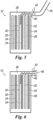
Figure 3 is a schematic view of the fluid flow paths of the heat exchanger ofFigure 1 , wherein the main components of the fluid leakage detecting system according to the invention are shown in a first embodiment thereof; -
Figure 4 is another schematic view of the fluid flow paths of the heat exchanger ofFigure 1 , wherein the main components of the fluid leakage detecting system according to the invention are shown in a second embodiment thereof; -
Figure 5 is a further schematic view of the fluid flow paths of the heat exchanger ofFigure 1 , wherein the main components of the fluid leakage detecting system according to the invention are shown in a third embodiment thereof; and -
Figure 6 is yet another schematic view of the fluid flow paths of the heat exchanger ofFigure 1 , wherein the main components of the fluid leakage detecting system according to the invention are shown in a fourth embodiment thereof. - With reference to the Figures, a
plate heat exchanger 10 is shown. Theheat exchanger 10 comprises, in a per se known manner, a plurality ofheat exchanger plates heat exchanger plates first end plate 14 and asecond end plate 16 of theheat exchanger 10. Thefirst end plate 14 and thesecond end plate 16 form the front and rear end plates of theheat exchanger 10, respectively. These front and rear end plates are also called "frame plate" and "pressure plate". The purpose of these front and rear end plates is to mechanically strengthen theheat exchanger 10, as well as to provide a support for the fluid connections of theheat exchanger 10. Eachheat exchanger plate - The
first end plate 14, thesecond end plate 16 and theheat exchanger plates plate package 30. For example, this joining technology can be a brazing technology by means of a braze material, a fusion bonding technology or any other technology known in the technical field of the plate heat exchangers. - The
plate package 30 is thus provided (see for exampleFigures 3-5 ) with first plate interspaces, which form respectivefirst channels 32 of a first circulation circuit for a first fluid, and second plate interspaces, which form respectivesecond channels 32 of a second circulation circuit for a second fluid. The first fluid and the second fluid may be any suitable heat transfer fluid. For example, the first fluid can be the hotter fluid and the second fluid can be the colder fluid. The second fluid is therefore the cooling fluid, and it receives the heat from the first fluid. - Each
heat exchanger plate first end plate 14 and thesecond end plate 16, is provided with a plurality of portholes, preferably four portholes P1, P2, P3 and P4. A first porthole P1 is connected to afirst connection pipe 18 and communicates with thefirst channels 32. A second porthole P2 is connected to asecond connection pipe 20 and communicates with thefirst channels 32. A third porthole P3 is connected to athird connection pipe 22 and communicates with thesecond channels 34. Finally, a fourth porthole P4 is connected to afourth connection pipe 24 and communicates with thesecond channels 34.Connection pipes first end plate 14, as shown inFigure 1 , and/or from thesecond end plate 16. - Each
heat exchanger plate first end plate 14 and thesecond end plate 16, can have the shape of any plane figure bounded by a closed line, such as a convex polygon or even a circle. Eachheat exchanger plate first end plate 14 and thesecond end plate 16, is thus provided with one or more side edges 26, 28, which form the outer perimeter of theheat exchanger plates - The
plate package 30 is also provided (see againFigures 3-5 ) with third plate interspaces, which formrespective separation channels 36 between thefirst channels 32 for the first fluid and thesecond channels 34 for the second fluid. Theseparation channels 36 are arranged adjacent to both thefirst channels 32 and thesecond channels 34. - Advantageously, a single
outlet fluid collector 38 is arranged on one of the side edges 26, 28 of theheat exchanger plates separation channels 36 are sealed with respect to thefirst channels 32, thesecond channels 34 and the side edges 26, 28 of theheat exchanger plates separation channels 36 are in fluid communication with the singleoutlet fluid collector 38. Asingle drain nozzle 40 is thus provided on the singleoutlet fluid collector 38 for the discharge to the external environment of any fluids flowing into theseparation channels 36 and through the singleoutlet fluid collector 38. - Due to this arrangement of the components of the
heat exchanger 10, in the event of a breakage in thefirst channels 32 of the first circulation circuit and/or thesecond channels 34 of the second circulation circuit, the leaking first fluid and/or second fluid goes into theseparation channels 36, since theseseparation channels 36 are immediately adjacent to thefirst channels 32 and thesecond channels 34. The leaking fluid, therefore, has no other exit pathways other than the singleoutlet fluid collector 38 and thesingle drain nozzle 40 located downstream of the latter. Consequently, the leaking fluid can be easily and quickly detected at thesingle drain nozzle 40. - Preferably, as shown in the Figures, each
heat exchanger plate first end plate 14 and thesecond end plate 16, has a substantially rectangular shape, with a first pair of side edges 26 (e.g., the long side edges) parallel to each other and a second pair of side edges 28 (e.g., the short side edges) also parallel to each other and perpendicular to the first pair of side edges 26. A longitudinal axis X extends parallel to the two long side edges 26 and transversely to the two short side edges 28. According to this embodiment of theheat exchanger 10, theseparation channels 36 are also parallel to each other, whereas the singleoutlet fluid collector 38 consists of an elongated channel which is arranged on one of the edges of either the first pair of side edges 26 or the second pair of side edges 28. The singleoutlet fluid collector 38 is thus arranged perpendicular to theseparation channels 36. This preferred linear arrangement of theseparation channels 36 and theoutlet fluid collector 38 is made to avoid traps or sealed barriers that could prevent the leaking fluid from reaching thedrain nozzle 40. - According to the embodiment of the
heat exchanger 10 shown inFigure 3 , theseparation channels 36 are empty under normal operating conditions of theheat exchanger 10. In other words, theseparation channels 36 are filled with ambient air and no fluid normally circulates in theseseparation channels 36 unless a breakage in thefirst channels 32 of the first circulation circuit and/or thesecond channels 34 of the second circulation circuit occur. - According to the embodiment of the
heat exchanger 10 shown inFigure 4 , theseparation channels 36 are filled with a liquid L which is still under normal operating conditions of theplate heat exchanger 10. The still liquid L, that is, a liquid that does not normally move within theseparation channels 36, can be any liquid suitable for enhancing the heat transfer between the first fluid and the second fluid, compared with the case where theseparation channels 36 are filled with ambient air. In this specific embodiment, the circuit formed by theseparation channels 36 can be provided with at least one small openable port (not shown), which is normally sealingly closed, and which is designed to facilitate the filling and/or refilling of the liquid L contained in theseseparation channels 36. - In the case where the
separation channels 36 are arranged to be filled with the liquid L, theheat exchanger 10 could be designed for an easy draining, filling, refilling, changing, or restoring of this liquid L during or after positioning/assembling, as well as during ordinary maintenance. In case of pre-filling, thedrain nozzle 40 must be closed to avoid liquid spilling out during transportation and during handling or installation of theheat exchanger 10. The liquid L must be suitable for working conditions and safety and environmental standards. - Preferably, the liquid L can be filled with additional substances. For example, these additional substances can be chosen from the group consisting of:
- conductivity-increasing substances (particles, nano particles, or fibers);
- phase change materials, to store and release heat during transient phases;
- odorous and/or colored substances, to enhance the leakage detection capability;
- a permeable gel, grease, or wax;
- a sand or a powder.
- According to a preferred aspect of the present invention, the
drain nozzle 40 can be provided with sensor means 42 for detecting the leakage of fluids through thedrain nozzle 40. For example, these sensor means 42 may include, but not be limited to, one single gas detector, one single liquid level probe or one single pressure switch. In the event of a breakage in thefirst channels 32 of the first circulation circuit and/or thesecond channels 34 of the second circulation circuit, the leaking first fluid and/or second fluid is forced to flow through thesingle drain nozzle 40, where its presence can be easily detected with one single sensor means 42. - According to the embodiment of the
heat exchanger 10 shown inFigure 5 , at least one piping 44 can be connected downstream of thedrain nozzle 40. The piping 44 is arranged to transport outside theplate heat exchanger 10 the fluid discharged from thedrain nozzle 40. By mounting an additional piping 44, the eventual leaked fluid could be easily driven from thedrain nozzle 40 to a safe place (e.g., outdoor ambient) for purging or detection. - According to the embodiment of the
heat exchanger 10 shown inFigure 6 , at least oneplug 46 can be tightly and removably engaged with thedrain nozzle 40. For example, thedrain nozzle 40 and theplug 46 can be provided with respective threaded connections having the same pitch, to obtain a threaded screw-to-nut coupling between theplug 46 and thedrain nozzle 40. With theplug 46, in case of leakage of the first fluid and/or the second fluid, thedrain nozzle 40 can be temporarily plugged, thus stopping the release of the fluid to the environment. This can prevent the release of the fluid to the environment while waiting for the fixing of theheat exchanger 10. During fixing, the fluid can be recovered and stored. In this case, theheat exchanger 10 should be turned off to avoid overpressures that could take to the breakage of theheat exchanger plates - It is thus seen that the plate heat exchanger according to the present invention achieve the previously outlined objects, specifically achieving the following advantages:
- only a single fluid leakage point to the environment;
- easier and faster leak detection, sensoring or visualization;
- it is possible to pipe and drive the eventual leak to a safer place;
- it is possible to temporary plug the fluid leakage point while waiting for fixing, reducing releasing of fluid (even recovering);
- better heat transfer (in case the separation channels are filled with liquid).
- The plate heat exchanger of the present invention can be a brazed plate heat exchanger or a fusion-bonded plate heat exchanger. Fusion bonded technology is typically used as an alternative to copper brazing technology when copper is not usable, for example when the fluids processed by the heat exchanger contain ammonia, or when local legislations do not allow the use of copper for drinking water circuits. Since the fusion-bonded plate heat exchangers are manufactured from only one type of material (stainless steel), they have definite advantages for the eventual recycling of that material at the end of its life compared to brazed plate heat exchangers.
- The plate heat exchanger of the present invention thus conceived is susceptible in any case of numerous modifications and variants, all falling within the same inventive concept; in addition, all the details can be substituted by technically equivalent elements. In practice, the materials used, as well as the shapes and size, can be of any type according to the technical requirements.
- The scope of protection of the invention is therefore defined by the enclosed claims.
-
- 10: plate heat exchanger;
- 12A: heat exchanger plate;
- 12B: heat exchanger plate;
- 14: first end plate;
- 16: second end plate;
- 18: first connection pipe;
- 20: second connection pipe;
- 22: third connection pipe;
- 24: fourth connection pipe;
- 26: plate long side edges;
- 28: plate short side edges;
- 30: plate package;
- 32: first fluid channels;
- 34: second fluid channels;
- 36: separation channels;
- 38: outlet fluid collector;
- 40: drain nozzle;
- 42: sensor means;
- 44: piping;
- 46: plug;
- P1: first porthole;
- P2: second porthole;
- P3: third porthole;
- P4: fourth porthole.
Claims (13)
- A plate heat exchanger (10) comprising a plurality of heat exchanger plates (12A, 12B, 14, 16) which are stacked onto one another, wherein said heat exchanger plates (12A, 12B, 14, 16) are obtained by forming from respective metal sheets, wherein said heat exchanger plates (12A, 12B, 14, 16) are permanently joined to each other through a joining technology of metallic materials, so as to form a plate package (30) provided with first plate interspaces, which form respective first channels (32) of a first circulation circuit for a first fluid, second plate interspaces, which form respective second channels (34) of a second circulation circuit for a second fluid, and third plate interspaces, which form respective separation channels (36) between said first channels (32) and said second channels (34), wherein said separation channels (36) are arranged adjacent to both said first channels (32) and said second channels (34), wherein each of said heat exchanger plates (12A, 12B, 14, 16) is provided with a plurality of portholes (P1, P2, P3, P4) which communicates with said first channels (32) and said second channels (34), and wherein each of said heat exchanger plates (12A, 12B, 14, 16) is provided with one or more side edges (26, 28) which form the outer perimeter of said heat exchanger plates (12A, 12B, 14, 16), the heat exchanger (10) being characterized in that a single outlet fluid collector (38) is arranged on one of said side edges (26, 28), wherein said separation channels (36) are sealed with respect to said first channels (32), said second channels (34) and said side edges (26, 28), and wherein said separation channels (36) are in fluid communication with said single outlet fluid collector (38) only, and in that a single drain nozzle (40) is provided on said single outlet fluid collector (38) for the discharge to the external environment of any fluids flowing into said separation channels (36) and through said single outlet fluid collector (38).
- The plate heat exchanger (10) according to claim 1, characterized in that said heat exchanger plates (12A, 12B, 14, 16) are of rectangular shape, with a first pair of side edges (26) parallel to each other and a second pair of side edges (28) parallel to each other and perpendicular to said first pair of side edges (26), wherein said separation channels (36) are also parallel to each other, and wherein said single outlet fluid collector (38) consists of an elongated channel which is arranged on one of the edges of either the first pair of side edges (26) or the second pair of side edges (28) and arranged perpendicular to said separation channels (36).
- The plate heat exchanger (10) according to claim 1 or 2, characterized in that said separation channels (36) are empty under normal operating conditions of the plate heat exchanger (10).
- The plate heat exchanger (10) according to claim 1 or 2, characterized in that said separation channels (36) are filled with a liquid (L) which is still under normal operating conditions of the plate heat exchanger (10), wherein said liquid (L) is capable of enhancing the heat transfer between said first fluid and said second fluid.
- The plate heat exchanger (10) according to claim 4, characterized in that said liquid (L) is filled with additional substances.
- The plate heat exchanger (10) according to claim 4, characterized in that said additional substances are chosen from the group consisting of:- conductivity-increasing substances;- phase change materials, to store and release heat during transient phases;- odorous and/or colored substances, to enhance the leakage detection capability;- a permeable gel, grease, or wax;- a sand or a powder.
- The plate heat exchanger (10) according to anyone of claims 1 to 6, characterized in that said drain nozzle (40) is provided with sensor means (42) for detecting the leakage of fluids through said drain nozzle (40).
- The plate heat exchanger (10) according to claim 7, characterized in that said sensor means (42) comprise one single gas detector.
- The plate heat exchanger (10) according to claim 7, characterized in that said sensor means (42) comprise one single liquid level probe.
- The plate heat exchanger (10) according to claim 7, characterized in that said sensor means (42) comprise one single pressure switch.
- The plate heat exchanger (10) according to anyone of claims 1 to 10, characterized in that at least one piping (44) is connected downstream of said drain nozzle (40), wherein said at least one piping (44) is arranged to transport outside the plate heat exchanger (10) the fluid discharged from said drain nozzle (40).
- The plate heat exchanger (10) according to anyone of claims 1 to 10, characterized in that at least one plug (46) is tightly and removably engaged with said drain nozzle (40).
- The plate heat exchanger (10) according to claim 12, characterized in that said drain nozzle (40) and said plug (46) are provided with respective threaded connections having the same pitch, to obtain a threaded screw-to-nut coupling between said plug (46) and said drain nozzle (40).
Priority Applications (5)
| Application Number | Priority Date | Filing Date | Title |
|---|---|---|---|
| EP23425038.9A EP4498029A1 (en) | 2023-07-28 | 2023-07-28 | Plate heat exchanger with improved fluid leakage detection system |
| CN202480049209.9A CN121646694A (en) | 2023-07-28 | 2024-07-10 | Plate heat exchanger with an improved fluid leak detection system |
| KR1020267002619A KR20260027327A (en) | 2023-07-28 | 2024-07-10 | Plate heat exchanger with improved fluid leak detection system |
| PCT/EP2024/069493 WO2025026677A1 (en) | 2023-07-28 | 2024-07-10 | Plate heat exchanger with improved fluid leakage detection system |
| TW113126171A TWI889452B (en) | 2023-07-28 | 2024-07-12 | Plate heat exchanger with improved fluid leakage detection system |
Applications Claiming Priority (1)
| Application Number | Priority Date | Filing Date | Title |
|---|---|---|---|
| EP23425038.9A EP4498029A1 (en) | 2023-07-28 | 2023-07-28 | Plate heat exchanger with improved fluid leakage detection system |
Publications (1)
| Publication Number | Publication Date |
|---|---|
| EP4498029A1 true EP4498029A1 (en) | 2025-01-29 |
Family
ID=88097960
Family Applications (1)
| Application Number | Title | Priority Date | Filing Date |
|---|---|---|---|
| EP23425038.9A Pending EP4498029A1 (en) | 2023-07-28 | 2023-07-28 | Plate heat exchanger with improved fluid leakage detection system |
Country Status (5)
| Country | Link |
|---|---|
| EP (1) | EP4498029A1 (en) |
| KR (1) | KR20260027327A (en) |
| CN (1) | CN121646694A (en) |
| TW (1) | TWI889452B (en) |
| WO (1) | WO2025026677A1 (en) |
Citations (8)
| Publication number | Priority date | Publication date | Assignee | Title |
|---|---|---|---|---|
| AU2011318649A1 (en) * | 2010-10-22 | 2013-04-18 | Alfa Laval Corporate Ab | A heat exchanger plate and a plate heat exchanger |
| US9163882B2 (en) | 2011-04-25 | 2015-10-20 | Itt Manufacturing Enterprises, Inc. | Plate heat exchanger with channels for ‘leaking fluid’ |
| US20160040943A1 (en) * | 2014-08-07 | 2016-02-11 | Kaori Heat Treatment Co., Ltd. | Heat exchanger |
| US9772146B2 (en) | 2011-11-11 | 2017-09-26 | Hisaka Works, Ltd. | Plate heat exchanger |
| US20180073811A1 (en) * | 2016-09-12 | 2018-03-15 | Climate Master, Inc. | Double-wall heat exchanger |
| CN111819415A (en) * | 2018-03-15 | 2020-10-23 | 三菱电机株式会社 | Plate heat exchanger, heat pump device equipped with plate heat exchanger, and heat pump cooling, heating and hot water supply system equipped with heat pump device |
| US20210033354A1 (en) * | 2019-07-29 | 2021-02-04 | Hamilton Sundstrand Corporation | Heat exchanger with barrier passages |
| WO2022015217A1 (en) * | 2020-07-17 | 2022-01-20 | Swep International Ab | A double wall plate heat exchanger |
Family Cites Families (2)
| Publication number | Priority date | Publication date | Assignee | Title |
|---|---|---|---|---|
| FR2927411B1 (en) * | 2008-02-13 | 2013-03-29 | Valeo Systemes Thermiques | MEANS FOR SEALING FOR A COLLECTOR HEAT EXCHANGER BOX |
| US10852076B2 (en) * | 2015-12-22 | 2020-12-01 | Dana Canada Corporation | Segmented conformal heat exchanger |
-
2023
- 2023-07-28 EP EP23425038.9A patent/EP4498029A1/en active Pending
-
2024
- 2024-07-10 CN CN202480049209.9A patent/CN121646694A/en active Pending
- 2024-07-10 KR KR1020267002619A patent/KR20260027327A/en active Pending
- 2024-07-10 WO PCT/EP2024/069493 patent/WO2025026677A1/en active Pending
- 2024-07-12 TW TW113126171A patent/TWI889452B/en active
Patent Citations (8)
| Publication number | Priority date | Publication date | Assignee | Title |
|---|---|---|---|---|
| AU2011318649A1 (en) * | 2010-10-22 | 2013-04-18 | Alfa Laval Corporate Ab | A heat exchanger plate and a plate heat exchanger |
| US9163882B2 (en) | 2011-04-25 | 2015-10-20 | Itt Manufacturing Enterprises, Inc. | Plate heat exchanger with channels for ‘leaking fluid’ |
| US9772146B2 (en) | 2011-11-11 | 2017-09-26 | Hisaka Works, Ltd. | Plate heat exchanger |
| US20160040943A1 (en) * | 2014-08-07 | 2016-02-11 | Kaori Heat Treatment Co., Ltd. | Heat exchanger |
| US20180073811A1 (en) * | 2016-09-12 | 2018-03-15 | Climate Master, Inc. | Double-wall heat exchanger |
| CN111819415A (en) * | 2018-03-15 | 2020-10-23 | 三菱电机株式会社 | Plate heat exchanger, heat pump device equipped with plate heat exchanger, and heat pump cooling, heating and hot water supply system equipped with heat pump device |
| US20210033354A1 (en) * | 2019-07-29 | 2021-02-04 | Hamilton Sundstrand Corporation | Heat exchanger with barrier passages |
| WO2022015217A1 (en) * | 2020-07-17 | 2022-01-20 | Swep International Ab | A double wall plate heat exchanger |
Also Published As
| Publication number | Publication date |
|---|---|
| KR20260027327A (en) | 2026-02-27 |
| TW202507221A (en) | 2025-02-16 |
| CN121646694A (en) | 2026-03-10 |
| WO2025026677A1 (en) | 2025-02-06 |
| TWI889452B (en) | 2025-07-01 |
Similar Documents
| Publication | Publication Date | Title |
|---|---|---|
| CN111819415B (en) | Plate heat exchanger, heat pump device provided with same, and heat pump type cooling/heating/water heating system provided with heat pump device | |
| CN101004329A (en) | Double-wall, vented heat exchanger | |
| EP2435774B1 (en) | Double-walled plate heat exchanger | |
| KR19990022246A (en) | heat transmitter | |
| US3590914A (en) | Countercurrent flow plate-type heat exchanger with leak detector | |
| US20140352934A1 (en) | Plate heat exchanger | |
| KR102073625B1 (en) | Printed circuit heat exchanger and heat exchanging device comprising it | |
| EP0503080B1 (en) | Laminated heat exchanger | |
| EP3298339B1 (en) | Heat exchanger and heat exchanger tank | |
| CN107917629B (en) | Double-wall plate and shell heat exchanger and its special double-wall heat exchange plate | |
| CN1328563C (en) | Plate-type heat exchanger with double-walled heat transfer plates | |
| EP3625510B1 (en) | Double wall printed circuit heat exchanger | |
| JP2020041752A (en) | Heat exchanger | |
| CN206399257U (en) | Double-wall plate and shell type heat exchanger and special double-wall heat exchange plate thereof | |
| WO2025026677A1 (en) | Plate heat exchanger with improved fluid leakage detection system | |
| US11933547B2 (en) | Double plate heat exchanger | |
| JP2006313030A (en) | Plate fin heat exchanger and manufacturing method thereof | |
| CN114719637A (en) | A leak-proof plate heat exchanger | |
| SE467893B (en) | CAR COOLERS WHEN THE RUBBER END WAS WELDED IN THE FLANES ON THE COOLING SIDE OF THE END PLATES AND LOADED ON THE AIR SIDE | |
| WO2021229934A1 (en) | Plate heat exchanger, heat pump system, and heat transfer plate manufacturing method | |
| CN115302167B (en) | Welding structure of multilayer annular micro-channel in stainless steel pipe | |
| EP4498028A1 (en) | Brazed plate heat exchanger with freezing detection system | |
| EP3742100A1 (en) | Plate heat exchanger | |
| EP4464971A1 (en) | Heat exchanger | |
| CN205825774U (en) | A kind of conjuncted box-like stacking heat exchanger with gas-liquid separation device |
Legal Events
| Date | Code | Title | Description |
|---|---|---|---|
| PUAI | Public reference made under article 153(3) epc to a published international application that has entered the european phase |
Free format text: ORIGINAL CODE: 0009012 |
|
| STAA | Information on the status of an ep patent application or granted ep patent |
Free format text: STATUS: THE APPLICATION HAS BEEN PUBLISHED |
|
| AK | Designated contracting states |
Kind code of ref document: A1 Designated state(s): AL AT BE BG CH CY CZ DE DK EE ES FI FR GB GR HR HU IE IS IT LI LT LU LV MC ME MK MT NL NO PL PT RO RS SE SI SK SM TR |
|
| STAA | Information on the status of an ep patent application or granted ep patent |
Free format text: STATUS: REQUEST FOR EXAMINATION WAS MADE |
|
| 17P | Request for examination filed |
Effective date: 20250605 |
|
| STAA | Information on the status of an ep patent application or granted ep patent |
Free format text: STATUS: EXAMINATION IS IN PROGRESS |
|
| 17Q | First examination report despatched |
Effective date: 20250916 |