EP4498024A1 - Vacuum insulated structure with a series evaporator - Google Patents
Vacuum insulated structure with a series evaporator Download PDFInfo
- Publication number
- EP4498024A1 EP4498024A1 EP24190603.1A EP24190603A EP4498024A1 EP 4498024 A1 EP4498024 A1 EP 4498024A1 EP 24190603 A EP24190603 A EP 24190603A EP 4498024 A1 EP4498024 A1 EP 4498024A1
- Authority
- EP
- European Patent Office
- Prior art keywords
- pass
- evaporator
- refrigerant
- compartment
- grommet
- Prior art date
- Legal status (The legal status is an assumption and is not a legal conclusion. Google has not performed a legal analysis and makes no representation as to the accuracy of the status listed.)
- Withdrawn
Links
Images




Classifications
-
- F—MECHANICAL ENGINEERING; LIGHTING; HEATING; WEAPONS; BLASTING
- F25—REFRIGERATION OR COOLING; COMBINED HEATING AND REFRIGERATION SYSTEMS; HEAT PUMP SYSTEMS; MANUFACTURE OR STORAGE OF ICE; LIQUEFACTION SOLIDIFICATION OF GASES
- F25B—REFRIGERATION MACHINES, PLANTS OR SYSTEMS; COMBINED HEATING AND REFRIGERATION SYSTEMS; HEAT PUMP SYSTEMS
- F25B5/00—Compression machines, plants or systems, with several evaporator circuits, e.g. for varying refrigerating capacity
- F25B5/04—Compression machines, plants or systems, with several evaporator circuits, e.g. for varying refrigerating capacity arranged in series
-
- F—MECHANICAL ENGINEERING; LIGHTING; HEATING; WEAPONS; BLASTING
- F25—REFRIGERATION OR COOLING; COMBINED HEATING AND REFRIGERATION SYSTEMS; HEAT PUMP SYSTEMS; MANUFACTURE OR STORAGE OF ICE; LIQUEFACTION SOLIDIFICATION OF GASES
- F25B—REFRIGERATION MACHINES, PLANTS OR SYSTEMS; COMBINED HEATING AND REFRIGERATION SYSTEMS; HEAT PUMP SYSTEMS
- F25B41/00—Fluid-circulation arrangements
- F25B41/20—Disposition of valves, e.g. of on-off valves or flow control valves
-
- F—MECHANICAL ENGINEERING; LIGHTING; HEATING; WEAPONS; BLASTING
- F25—REFRIGERATION OR COOLING; COMBINED HEATING AND REFRIGERATION SYSTEMS; HEAT PUMP SYSTEMS; MANUFACTURE OR STORAGE OF ICE; LIQUEFACTION SOLIDIFICATION OF GASES
- F25B—REFRIGERATION MACHINES, PLANTS OR SYSTEMS; COMBINED HEATING AND REFRIGERATION SYSTEMS; HEAT PUMP SYSTEMS
- F25B41/00—Fluid-circulation arrangements
- F25B41/30—Expansion means; Dispositions thereof
- F25B41/37—Capillary tubes
-
- F—MECHANICAL ENGINEERING; LIGHTING; HEATING; WEAPONS; BLASTING
- F25—REFRIGERATION OR COOLING; COMBINED HEATING AND REFRIGERATION SYSTEMS; HEAT PUMP SYSTEMS; MANUFACTURE OR STORAGE OF ICE; LIQUEFACTION SOLIDIFICATION OF GASES
- F25B—REFRIGERATION MACHINES, PLANTS OR SYSTEMS; COMBINED HEATING AND REFRIGERATION SYSTEMS; HEAT PUMP SYSTEMS
- F25B41/00—Fluid-circulation arrangements
- F25B41/30—Expansion means; Dispositions thereof
- F25B41/385—Dispositions with two or more expansion means arranged in parallel on a refrigerant line leading to the same evaporator
-
- F—MECHANICAL ENGINEERING; LIGHTING; HEATING; WEAPONS; BLASTING
- F25—REFRIGERATION OR COOLING; COMBINED HEATING AND REFRIGERATION SYSTEMS; HEAT PUMP SYSTEMS; MANUFACTURE OR STORAGE OF ICE; LIQUEFACTION SOLIDIFICATION OF GASES
- F25B—REFRIGERATION MACHINES, PLANTS OR SYSTEMS; COMBINED HEATING AND REFRIGERATION SYSTEMS; HEAT PUMP SYSTEMS
- F25B41/00—Fluid-circulation arrangements
- F25B41/40—Fluid line arrangements
-
- F—MECHANICAL ENGINEERING; LIGHTING; HEATING; WEAPONS; BLASTING
- F25—REFRIGERATION OR COOLING; COMBINED HEATING AND REFRIGERATION SYSTEMS; HEAT PUMP SYSTEMS; MANUFACTURE OR STORAGE OF ICE; LIQUEFACTION SOLIDIFICATION OF GASES
- F25B—REFRIGERATION MACHINES, PLANTS OR SYSTEMS; COMBINED HEATING AND REFRIGERATION SYSTEMS; HEAT PUMP SYSTEMS
- F25B5/00—Compression machines, plants or systems, with several evaporator circuits, e.g. for varying refrigerating capacity
- F25B5/02—Compression machines, plants or systems, with several evaporator circuits, e.g. for varying refrigerating capacity arranged in parallel
-
- F—MECHANICAL ENGINEERING; LIGHTING; HEATING; WEAPONS; BLASTING
- F25—REFRIGERATION OR COOLING; COMBINED HEATING AND REFRIGERATION SYSTEMS; HEAT PUMP SYSTEMS; MANUFACTURE OR STORAGE OF ICE; LIQUEFACTION SOLIDIFICATION OF GASES
- F25D—REFRIGERATORS; COLD ROOMS; ICE-BOXES; COOLING OR FREEZING APPARATUS NOT OTHERWISE PROVIDED FOR
- F25D11/00—Self-contained movable devices, e.g. domestic refrigerators
- F25D11/02—Self-contained movable devices, e.g. domestic refrigerators with cooling compartments at different temperatures
- F25D11/022—Self-contained movable devices, e.g. domestic refrigerators with cooling compartments at different temperatures with two or more evaporators
-
- F—MECHANICAL ENGINEERING; LIGHTING; HEATING; WEAPONS; BLASTING
- F25—REFRIGERATION OR COOLING; COMBINED HEATING AND REFRIGERATION SYSTEMS; HEAT PUMP SYSTEMS; MANUFACTURE OR STORAGE OF ICE; LIQUEFACTION SOLIDIFICATION OF GASES
- F25D—REFRIGERATORS; COLD ROOMS; ICE-BOXES; COOLING OR FREEZING APPARATUS NOT OTHERWISE PROVIDED FOR
- F25D17/00—Arrangements for circulating cooling fluids; Arrangements for circulating gas, e.g. air, within refrigerated spaces
- F25D17/04—Arrangements for circulating cooling fluids; Arrangements for circulating gas, e.g. air, within refrigerated spaces for circulating air, e.g. by convection
- F25D17/06—Arrangements for circulating cooling fluids; Arrangements for circulating gas, e.g. air, within refrigerated spaces for circulating air, e.g. by convection by forced circulation
- F25D17/062—Arrangements for circulating cooling fluids; Arrangements for circulating gas, e.g. air, within refrigerated spaces for circulating air, e.g. by convection by forced circulation in household refrigerators
- F25D17/065—Arrangements for circulating cooling fluids; Arrangements for circulating gas, e.g. air, within refrigerated spaces for circulating air, e.g. by convection by forced circulation in household refrigerators with compartments at different temperatures
-
- F—MECHANICAL ENGINEERING; LIGHTING; HEATING; WEAPONS; BLASTING
- F25—REFRIGERATION OR COOLING; COMBINED HEATING AND REFRIGERATION SYSTEMS; HEAT PUMP SYSTEMS; MANUFACTURE OR STORAGE OF ICE; LIQUEFACTION SOLIDIFICATION OF GASES
- F25D—REFRIGERATORS; COLD ROOMS; ICE-BOXES; COOLING OR FREEZING APPARATUS NOT OTHERWISE PROVIDED FOR
- F25D23/00—General constructional features
- F25D23/06—Walls
- F25D23/061—Walls with conduit means
-
- F—MECHANICAL ENGINEERING; LIGHTING; HEATING; WEAPONS; BLASTING
- F25—REFRIGERATION OR COOLING; COMBINED HEATING AND REFRIGERATION SYSTEMS; HEAT PUMP SYSTEMS; MANUFACTURE OR STORAGE OF ICE; LIQUEFACTION SOLIDIFICATION OF GASES
- F25D—REFRIGERATORS; COLD ROOMS; ICE-BOXES; COOLING OR FREEZING APPARATUS NOT OTHERWISE PROVIDED FOR
- F25D23/00—General constructional features
- F25D23/06—Walls
- F25D23/062—Walls defining a cabinet
-
- F—MECHANICAL ENGINEERING; LIGHTING; HEATING; WEAPONS; BLASTING
- F25—REFRIGERATION OR COOLING; COMBINED HEATING AND REFRIGERATION SYSTEMS; HEAT PUMP SYSTEMS; MANUFACTURE OR STORAGE OF ICE; LIQUEFACTION SOLIDIFICATION OF GASES
- F25D—REFRIGERATORS; COLD ROOMS; ICE-BOXES; COOLING OR FREEZING APPARATUS NOT OTHERWISE PROVIDED FOR
- F25D23/00—General constructional features
- F25D23/06—Walls
- F25D23/065—Details
- F25D23/068—Arrangements for circulating fluids through the insulating material
-
- F—MECHANICAL ENGINEERING; LIGHTING; HEATING; WEAPONS; BLASTING
- F25—REFRIGERATION OR COOLING; COMBINED HEATING AND REFRIGERATION SYSTEMS; HEAT PUMP SYSTEMS; MANUFACTURE OR STORAGE OF ICE; LIQUEFACTION SOLIDIFICATION OF GASES
- F25B—REFRIGERATION MACHINES, PLANTS OR SYSTEMS; COMBINED HEATING AND REFRIGERATION SYSTEMS; HEAT PUMP SYSTEMS
- F25B2600/00—Control issues
- F25B2600/25—Control of valves
- F25B2600/2511—Evaporator distribution valves
-
- F—MECHANICAL ENGINEERING; LIGHTING; HEATING; WEAPONS; BLASTING
- F25—REFRIGERATION OR COOLING; COMBINED HEATING AND REFRIGERATION SYSTEMS; HEAT PUMP SYSTEMS; MANUFACTURE OR STORAGE OF ICE; LIQUEFACTION SOLIDIFICATION OF GASES
- F25D—REFRIGERATORS; COLD ROOMS; ICE-BOXES; COOLING OR FREEZING APPARATUS NOT OTHERWISE PROVIDED FOR
- F25D2201/00—Insulation
- F25D2201/10—Insulation with respect to heat
- F25D2201/14—Insulation with respect to heat using subatmospheric pressure
-
- F—MECHANICAL ENGINEERING; LIGHTING; HEATING; WEAPONS; BLASTING
- F25—REFRIGERATION OR COOLING; COMBINED HEATING AND REFRIGERATION SYSTEMS; HEAT PUMP SYSTEMS; MANUFACTURE OR STORAGE OF ICE; LIQUEFACTION SOLIDIFICATION OF GASES
- F25D—REFRIGERATORS; COLD ROOMS; ICE-BOXES; COOLING OR FREEZING APPARATUS NOT OTHERWISE PROVIDED FOR
- F25D2321/00—Details or arrangements for defrosting; Preventing frosting; Removing condensed or defrost water, not provided for in other groups of this subclass
- F25D2321/14—Collecting condense or defrost water; Removing condense or defrost water
- F25D2321/143—Collecting condense or defrost water; Removing condense or defrost water characterised by means to fix, clamp, or connect water pipes or evaporation trays
-
- F—MECHANICAL ENGINEERING; LIGHTING; HEATING; WEAPONS; BLASTING
- F25—REFRIGERATION OR COOLING; COMBINED HEATING AND REFRIGERATION SYSTEMS; HEAT PUMP SYSTEMS; MANUFACTURE OR STORAGE OF ICE; LIQUEFACTION SOLIDIFICATION OF GASES
- F25D—REFRIGERATORS; COLD ROOMS; ICE-BOXES; COOLING OR FREEZING APPARATUS NOT OTHERWISE PROVIDED FOR
- F25D2400/00—General features of, or devices for refrigerators, cold rooms, ice-boxes, or for cooling or freezing apparatus not covered by any other subclass
- F25D2400/04—Refrigerators with a horizontal mullion
Definitions
- the present disclosure generally relates to a vacuum insulated structure, and more specifically, to a vacuum insulated structure with a series evaporator system.
- a refrigeration unit includes a cabinet that defines a refrigerator compartment, a freezer compartment, and a machine compartment.
- the cabinet includes a mullion region between the refrigerator compartment and the freezer compartment, a first pass-through therethrough providing access from an external environment to the refrigerator compartment, and a second pass-through therethrough providing access from the external environment to the freezer compartment.
- the cabinet further includes a third pass-through extending through the mullion region, and a refrigerant system.
- the refrigerant system includes a three-way valve configured to direct a refrigerant down a first flow path or a second flow path.
- the refrigerant in the first flow path flows through the first pass-through, a first evaporator, the third pass-through, and the second evaporator, and the refrigerant in the second flow path flows through the second pass-through and the second evaporator.
- a refrigeration unit includes a cabinet defining a refrigerator compartment, a freezer compartment, and a machine compartment.
- the cabinet also includes a wrapper, a liner encompassed by the wrapper, a mullion region between the refrigerator compartment and the freezer compartment, a first pass-through therethrough providing access from an external environment to the refrigerator compartment, a second pass-through therethrough providing access from the external environment to the freezer compartment, a third pass-through extending through the mullion region, and a refrigerant system.
- the refrigerant system includes a first refrigerant flow path, where a refrigerant is directed through the first pass-through, a first evaporator, the third pass-through, and a second evaporator in the first refrigerant flow path.
- the refrigerant system also includes a second refrigerant flow path, where the refrigerant is directed through the second pass-through and the second evaporator in the second refrigerant flow path.
- a vacuum insulated refrigeration appliance includes a cabinet that defines a refrigerator compartment, a freezer compartment, and a mullion region between the refrigerator compartment and the freezer compartment.
- a first pass-through is defined through the mullion region, and a second pass-through extends through the cabinet and provides access from an external environment to the refrigerator compartment.
- the appliance also includes a first service line extending through the second pass-through and into the refrigerator compartment.
- the second service line includes at least one branch extending through the first pass-through and into the freezer compartment.
- the refrigerant system includes a first evaporator, a second evaporator, and a three-way valve that selectively directs a refrigerant along at least one of a first flow path through the first evaporator, the pass-through, and the second evaporator, and a second flow path through the second evaporator.
- the first evaporator and the second evaporator are arranged in series along the first flow path.
- the refrigerant at least partially flows along the at least one branch along the first flow path.
- the terms “upper,” “lower,” “right,” “left,” “rear,” “front,” “vertical,” “horizontal,” and derivatives thereof shall relate to the disclosure as oriented in FIG. 1 .
- the term “front” shall refer to the surface of the element closer to an intended viewer, and the term “rear” shall refer to the surface of the element further from the intended viewer.
- the disclosure may assume various alternative orientations, except where expressly specified to the contrary.
- the specific devices and processes illustrated in the attached drawings, and described in the following specification are simply exemplary embodiments of the inventive concepts defined in the appended claims. Hence, specific dimensions and other physical characteristics relating to the embodiments disclosed herein are not to be considered as limiting, unless the claims expressly state otherwise.
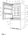
- reference numeral 10 generally designates a refrigeration appliance 10.
- the refrigeration appliance 10 includes a cabinet 12 that defines a refrigerator compartment 14, a freezer compartment 16, and a machine compartment 18.
- a mullion region 20 is defined by the cabinet 12 between the refrigerator compartment 14 and the freezer compartment 16.
- a first pass-through 22 is defined by and extends through the cabinet 12 to provide access from an external environment 24 to the refrigerator compartment 14.
- a second pass-through 26 is defined by and extends through the cabinet 12 to provide access from the external environment 24 to the freezer compartment 16.
- a third pass-through 28 is defined by the cabinet 12 and extends through the mullion region 20.
- the refrigeration appliance 10 also includes a refrigerant system 30.
- the refrigerant system 30 includes a three-way valve 32 that is configured to selectively direct refrigerant along a first flow path 34 and a second flow path 36.
- the refrigerant in the first flow path 34 flows through the first pass-through 22, a first evaporator 38, the third pass-through 28, and a second evaporator 40.
- the refrigerant in the second flow path 36 flows through the second pass-through 26 and through the second evaporator 40.
- the appliance 10 is illustrated as a vacuum insulated refrigeration appliance, however, it is contemplated that the appliance 10 disclosed herein may be a variety of appliances, structures, or for insulation purposes other than with an appliance 10.
- the refrigeration appliance 10 is illustrated as a bottom-mount refrigerator having an insulated door 50 and a pull-out drawer 52, which can both have substantially similar configurations, as discussed further herein.
- the cabinet 12 of the illustrated appliance 10 includes an upper compartment configured as the refrigerator compartment 14 and a lower compartment configured as the freezer compartment 16. In this way, the refrigerator and freezer compartments 14, 16 defined by the cabinet 12 can be sealed with the insulated door 50 and the pull-out drawer 52, respectively.
- the appliance 10 may be, for example, a bottom-mount French door refrigerator, a top-mount refrigerator, a side-by-side refrigerator, a 4-door French door refrigerator, and/or a 5-door French door refrigerator. Further, the present disclosure is not limited to refrigerators.
- the appliance 10 may be, for example, a freezer, a cooler, a vacuum insulated structure, and/or other similar appliances and fixtures within household and commercial settings.
- the cabinet 12 of the appliance 10 is an insulated structure having a vacuum insulated cavity 60 defined between a wrapper 62 and a liner 64.
- the insulated door 50, and the pull-out drawer 52 are insulated structures having a door vacuum insulated cavity 66 defined between a door wrapper 68 coupled to a door liner 70.
- Each of the vacuum insulated cavities 60, 66 of the cabinet 12 and the insulated doors 50, 52 typically includes one or more insulation materials disposed therein. It is generally contemplated that the insulation materials may be glass-type materials, carbon-based powders, silicon oxide-based materials, silica-based materials, insulating gases, and other standard insulation materials known in the art.
- the insulation materials substantially fill the vacuum insulated cavity 60, forming a substantially continuous layer between the wrapper 62 and the liner 64.
- the insulation materials substantially fill the door vacuum insulated cavity 66, forming a substantially continuous layer between the door wrapper 68 and the door liner 70.
- the insulated cavities 60, 66 are filled with the insulation materials using a load port on the cabinet 12 and the insulated doors 50, 52 respectively.
- the cabinet 12 and the insulated doors 50, 52 each defined an evacuation port for applying a vacuum or negative pressure to the insulated cavities 60, 66.
- An at least partial vacuum 72 is defined within the vacuum insulated cavities 60, 66.
- the at least partial vacuum 72 defines a pressure differential between an exterior of the appliance 10 and the vacuum insulated cavities 60, 66.
- the pressure differential serves to define an inward compressive force that is exerted on both the wrapper 62 and the liner 64 and tends to bias the wrapper 62 and the liner 64 towards the vacuum insulated cavity 60.
- the pressure differential and the inward compressive force are also exerted on both the door wrapper 68 and the door liner 70 of the insulated doors 50, 52 and tend to bias the door wrapper 68 and the door liner 70 towards the vacuum insulated cavity 66 in a similar manner.
- the wrapper 62, the liner 64, the door wrapper 68, and the door liner 70 are made from a material at least partially resistant to bending, deformation, or otherwise being formed in response to an inward compressive force.
- These materials for the wrapper 62, the door wrapper 68, the liner 64, and the door liner 70 include, but are not limited to, metals, polymers, metal alloys, combinations thereof, and/or other similar substantially rigid materials that can be used for vacuum insulated appliances and structures.
- the vacuum insulated structure 10 includes the wrapper 62, the liner 64 coupled to the wrapper 62, and a trim breaker 80 coupled to the wrapper 62 and the liner 64.
- the wrapper 62 generally faces the liner 64 and at least partially encompasses the liner 64.
- the vacuum insulated cavity 60 is defined in the space between the wrapper 62 and the liner 64, and the trim breaker 80 seals the vacuum insulated cavity 60.
- the reduced pressure within the vacuum insulated cavity 60 relative to the external environment 24 is such that a rate of heat transfer between the external environment 24 and the refrigerator compartment 14 and/or the freezer compartment 16 is reduced.
- the cabinet 12 defines the refrigerator compartment 14 and the freezer compartment 16.
- the refrigerator compartment 14 and the freezer compartment 16 are maintained at different temperatures.
- the refrigerator compartment 14 can be configured to maintain a temperature above about 0 °C but below the ambient temperature of the external environment 24, such as within a range from greater than about 0 °C to about 8 °C.
- the refrigerator compartment 14 is used to maintain a food item disposed therein at a cold but not freezing temperature to prolong the usable life of the food item.
- the freezer compartment 16 can be configured to maintain a temperature that is less than or equal to about 0 °C.
- the freezer compartment 16 is used to maintain the food item disposed therein in a frozen state to prolong the usable life of the food item.
- the refrigerator compartment 14 can be disposed above the freezer compartment 16, as in the illustrated example of FIG. 3 , although other configurations are generally contemplated.
- the refrigerator compartment 14 is defined by a floor 90, a ceiling 92 opposing the floor 90, a first sidewall 94, a second sidewall 96 opposing the first sidewall 94, and a rear wall 98.
- the refrigerator compartment 14 also defines an opening 100 that opposes the rear wall 98 and operably provides access to the refrigerator compartment 14.
- the opening 100 is operably sealed from the external environment 24 via the insulated door 50, which is pivotable between an opened position and a closed position.
- the liner 64 of the vacuum insulated structure 10 provides the floor 90, the ceiling 92, the first sidewall 94, the second sidewall 96, and the rear wall 98 of the refrigerator compartment 14.
- the freezer compartment 16 likewise is defined by a floor 110, a ceiling 112 opposing the floor 110, a first sidewall 114, a second sidewall 116 opposing the first sidewall 114, and a rear wall 118.
- the freezer compartment 16 also defines an opening 120 that opposes the rear wall 118 and operably provides access to the freezer compartment 16.
- the opening 120 to the freezer compartment 16 is operably sealed from the external environment 24 via the pull-out drawer 52, which is movable between an opened position and a closed position.
- the liner 64 of the vacuum insulated structure 10 provides the floor 110, the ceiling 112, the first sidewall 114, the second sidewall 116, and the rear wall 118 of the freezer compartment 16.
- the mullion region 20 is defined between the refrigerator compartment 14 and the freezer compartment 16.
- the floor 90 of the refrigerator compartment 14 may define a top section 130 of the mullion region 20 and the ceiling 112 of the freezer compartment 16 may define a bottom section 132 of the mullion region 20.
- the liner 64 may be defined such that the vacuum insulated cavity 60 extends from a rear portion 134 of the cabinet 12, between the refrigerator compartment 14 and the freezer compartment 16, and toward the openings 100, 120 of the refrigerator compartment 14 and the freezer compartment 16.
- the refrigeration appliance 10 includes the refrigerant system 30 that has the first evaporator 38.
- the first evaporator 38 is disposed within the refrigerator compartment 14.
- the first evaporator 38 is disposed adjacent the liner 64 of the vacuum insulated structure 10.
- the first evaporator 38 is disposed on the rear wall 98 of the refrigerator compartment 14.
- the first evaporator 38 is a roll bond evaporator that is coupled to the rear wall 98 of the refrigerator compartment 14.
- the first evaporator 38 may be disposed behind a cover panel 142 such that the first evaporator 38 is hidden when viewing the refrigerator compartment 14 through the opening 100.
- the first evaporator 38 withdraws heat from the refrigerator compartment 14 in order to maintain the temperature of the refrigerator compartment 14 below ambient temperature.
- the first evaporator 38 may withdraw heat from the refrigerator compartment 14 to maintain the temperature within the refrigerator compartment 14 at a desired temperature, such as a temperature that is from about 0 °C to about 8 °C.
- the refrigerant system 30 includes a first evaporator fan 150 proximate the first evaporator 38.
- the first evaporator fan 150 may be a triple-bladed fan that is positioned proximate the first evaporator 38.
- the first evaporator fan 150 is positioned relative to the first evaporator 38 such that the first evaporator fan 150 pushes and/or pulls an airflow across the first evaporator 38 to assist in heat transfer between the first evaporator 38 and the airflow within the refrigerator compartment 14.
- the first evaporator fan 150 may be positioned on the floor 90 near the rear wall 98 and facing towards the opening 100 of the refrigerator compartment 14 such that an airflow is pulled down the rear wall 98, across a top section 152 of the first evaporator 38 and then a bottom section 154 of the first evaporator 38, and out of the first evaporator fan 150. As the airflow flows across the first evaporator 38, the thermal transfer occurs such that the airflow within the refrigerator compartment 14 is cooled.
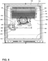
- the refrigerant system 30 includes the second evaporator 40.
- the second evaporator 40 is disposed within the freezer compartment 16.
- the second evaporator 40 is disposed adjacent the liner 64 of the vacuum insulated structure 10.
- the second evaporator 40 is disposed proximate the rear wall 118 and the ceiling 112 of the freezer compartment 16 such that a rear portion 160 of the second evaporator 40 is proximate the rear wall 118 of the freezer compartment 16 and a top section 162 of the second evaporator 40 abuts and/or is proximate the ceiling 112 of the freezer compartment 16.
- the second evaporator 40 may be a plate-and-tube evaporator that is coupled to the ceiling 112 and/or rear wall 118 of the freezer compartment 16.
- the second evaporator 40 may be disposed behind a cover panel 164 such that the second evaporator 40 is hidden when viewing the freezer compartment 16 through the opening 120.
- the second evaporator 40 withdraws heat from the freezer compartment 16 in order to maintain the temperature of the freezer compartment 16 below ambient temperature.
- the second evaporator 40 may withdraw heat from the freezer compartment 16 to maintain the temperature within the freezer compartment 16 at a desired temperature, such as a temperature that is below about 0 °C.
- the refrigerant system 30 includes a second evaporator fan 170 proximate the second evaporator 40.
- the second evaporator fan 170 may be a triple-bladed fan that is disposed proximate the second evaporator 40.
- the second evaporator fan 170 is positioned relative to the second evaporator 40 such that the second evaporator fan 170 pushes and/or pulls an airflow across the second evaporator 40.
- the second evaporator fan 170 may be positioned on the ceiling 112 proximate the rear panel 118 and facing towards the opening 120 of the freezer compartment 16 such that an airflow is pulled up along the rear panel 118, across the second evaporator 40, and out of the second evaporator fan 170. As the airflow flows across the second evaporator 40, the thermal transfer occurs such that the airflow within the freezer compartment 16 is cooled.
- the vacuum insulated structure 10 includes the first pass-through 22 that extends from the external environment 24 to the refrigerator compartment 14.
- the first pass-through 22 is defined by a first wrapper aperture 180, which may be defined on a rear panel 182 of the wrapper 62, and a first liner aperture 184 defined by the rear wall 118 of the liner 64 and generally aligns with the first wrapper aperture 180.
- the first wrapper aperture 180 and the first liner aperture 184 may be defined such that the first pass-through 22 defines a circular shape, an oblong shape, or one of various other shapes.
- the first wrapper aperture 180 and the first liner aperture 184 are positioned on the wrapper 62 and the liner 64, respectively, such that passage is permitted between the external environment 24 and the refrigerator compartment 14.
- the alignment of the first wrapper aperture 180 and the first liner aperture 184 is such that various components are permitted to extend through the first pass-through 22 from the external environment 24 and into the refrigerator compartment 14, as provided herein.
- the refrigeration appliance 10 includes a first service line 190.
- the first service line 190 extends from the external environment 24, through the first pass-through 22, and into the refrigerator compartment 14. In some examples, the first service line 190 extends into the refrigerator compartment 14 and diverges. In such examples, a first branch 192 of the first service line 190 extends along the rear wall 98 of the refrigerator compartment 14 and towards the ceiling 92 of the refrigerator compartment 14, and a second branch 194 of the first service line 190 extends towards the freezer compartment 16, as provided herein.
- the first service line 190 may include an insulative sleeve 200 and one or more connectors and/or connection lines disposed within the insulative sleeve 200 for fluid and/or electrical connections within the appliance 10.
- the first service line 190 includes a first capillary tube 202 and a first suction line 204 extending within the insulative sleeve 200.
- the first capillary tube 202 and the first suction line 204 both extend along the first service line 190, through the first branch 192, and towards the first evaporator 38, as provided herein.
- the first capillary tube 202 and the first suction line 204 may be positioned within the first service line 190 such that the first capillary tube 202 and the first suction line 204 are either proximate or distal from each other.
- the first capillary tube 202 and the first suction line 204 may be abutting as both the first capillary tube 202 and the first suction line 204 extend along the first branch 192.
- the close proximity may permit the transfer of thermal energy between the first capillary tube 202 and the first suction line 204.
- one or more additional lines may extend through the first pass-through 22 and into the refrigerator compartment 14.
- an additional suction line heat exchanger line may extend through the first pass-through 22 and into the refrigerator compartment 14.
- the first capillary tube 202 and the first suction line 204 are in fluid communication with the first evaporator 38.
- the first capillary tube 202 extends from the three-way valve 32 to an inlet 210 of the first evaporator 38.
- the first capillary tube 202 carries or guides the refrigerant to the first evaporator 38.
- the first suction line 204 extends from an outlet 212 of the first evaporator 38, along the first branch 192, then the second branch 194, and then to the second evaporator 40.
- the first suction line 204 carries refrigerant away from the first evaporator 38 and towards the second evaporator 40.
- the first capillary tube 202 extends from the three-way valve 32, through the first service line 190 and along the first branch 192, and to the inlet 210 at a top portion of the first evaporator 38, and the suction line 204 is coupled to the outlet 212 of the first evaporator 38 and extends away from the first evaporator 38 along the first branch 192 and the second branch 192, and then towards the second evaporator 40.
- the refrigeration appliance 10 includes a first drain tube 220.
- the first drain tube 220 extends from the external environment 24, through the first pass-through 22, and into the refrigerator compartment 14.
- the first drain tube 220 extends from a drain pan in the external environment 24, such as in the machine compartment 18, through the first pass-through 22, and up the rear wall 98 of the refrigerator compartment 14 to a collection pan 224 that is disposed underneath the first evaporator 38.
- the first drain tube 220 directs condensation that accumulates on the collection pan 224 to the drain pan that is disposed in the machine compartment 18.
- the refrigeration appliance 10 includes a first pass-through grommet 230 disposed within the first pass-through 22.
- the first pass-through grommet 230 may have a shape that coincides with the shape of the first pass-through 22.
- the first pass-through grommet 230 may have an oblong, circular, or one of other various shapes.
- the first pass-through grommet 230 may be disposed in the pass-through 22 such that a rear portion 232 of the first pass-through grommet 230 is recessed, flush, or protruding from the wrapper 62 and a front portion 234 of the first pass-through grommet 230 is recessed, flush, or protruding from the liner 64.
- the first pass-through grommet 230 substantially fills the first pass-through 22 to maintain an air-tight seal within the vacuum insulated cavity 60 about the first pass-through 22.
- the air-tight seal defined by the first pass-through grommet 230 is configured to reduce or prevent the flow of air from the external environment 24 and into the refrigerator compartment 14.
- the first pass-through grommet 230 may be configured to maintain the vacuum within the vacuum insulated cavity 60 while still permitting a connecting channel to extend through the vacuum insulated cavity 60, as provided herein.
- the first pass-through grommet 230 may be oversized relative to the first pass-through 22 such that the air-tight seal may be at least partially maintained. It is also generally contemplated that the first pass-through grommet 230 may include components or structures that assist in at least partially maintaining the air-tight seal. For example, the first pass-through grommet 230 may include ribs or one or more sealing O-rings. It is further generally contemplated that the first pass-through grommet 230 can have a rubber or elastomeric composition and be slightly oversized relative to the first wrapper aperture 180 and the first liner aperture 184.
- the first drain tube 220 and the first service line 190 extend through the first pass-through grommet 230.
- the first pass-through grommet 230 forms an air-tight seal around the first drain tube 220 and the first service line 190.
- the first pass-through grommet 230 may define a first drain tube aperture 240, through which the first drain tube 220 extends, and a first service line aperture 242, through which the first service line 190 extends.
- the first drain tube aperture 240 and the first service line aperture 242 may be sized slightly smaller than the outer diameters of the first drain tube 220 and the first service line 190, respectively, to assist in maintaining the air-tight seal.
- the air-tight fitting of the first pass-through grommet 230 around the first drain tube 220 and the service line 190 helps limit heat transfer between the external environment 24 and the refrigerator compartment 14 through the first drain tube aperture 240 and the first service line aperture 242.
- the first pass-through grommet 230 may include an insulative material encircling the first drain tube aperture 240 and/or the first service line aperture 242 to assist in limiting heat transfer between the external environment 24 and the refrigerator compartment 14 through the first drain tube aperture 240 and the first service line aperture 242. It is further generally contemplated that the first pass-through grommet 230 may include one or more apertures that permit the extension of various other components through the first pass-through grommet 230.
- the first pass-through grommet 230 may include an aperture 244 configured to permit the extension of an electrical harness, electrical wiring, and/or other physical or electrical connectors through the first pass-through grommet 230 to power various features, such the first evaporator fan 150 and various other features.
- the vacuum insulated structure 10 includes the second pass-through 26 that extends from the external environment 24 to the freezer compartment 16.
- the second pass-through 26 is defined by a second wrapper aperture 250, which may be defined on the rear panel 182 of the wrapper 62, and a second liner aperture 252 defined on the rear wall 118 of the freezer compartment 16 and generally aligns with the second wrapper aperture 250.
- the second wrapper aperture 250 and the second liner aperture 252 may be defined such that the second pass-through 26 defines a circular shape, an oblong shape, or one of various other shapes.
- the second wrapper aperture 250 and the second liner aperture 252 are positioned on the wrapper 62 and the liner 64, respectively, such that passage is permitted between the external environment 24 and the freezer compartment 16. According to various aspects, the alignment of the second wrapper aperture 250 and the second liner aperture 252 is such that various components are permitted to extend through the second pass-through 26 from the external environment 24 and into the freezer compartment 16, as provided herein.
- the refrigeration appliance 10 includes a second service line 260.
- the second service line 260 extends from the external environment 24, through the second pass-through 26, and into the freezer compartment 16. In some examples, the second service line 260 extends into the freezer compartment 16 and then along the rear wall 118 of the freezer compartment 16 and towards the ceiling 112 of the freezer compartment 16. Additionally, it is generally contemplated that one or more additional lines may extend through the second pass-through 26 and into the freezer compartment 16. For example, an additional suction line heat exchanger line may extend through the second pass-through 26 and into the freezer compartment 16.
- the second service line 260 may include an insulative sleeve 262 and one or more connectors and/or connection lines disposed within the insulative sleeve 262 for fluid and/or electrical connections within the appliance 10.
- the second service line 260 includes a second capillary tube 264 and a second suction line 266 extending along and within the insulative sleeve 262.
- the second capillary tube 264 and the second suction line 266 may both extend along the second service line 260 and out of an end of the second service line 260.
- the second capillary tube 264 and the second suction line 266 may be positioned within the second service line 260 such that the second capillary tube 264 and the second suction line 266 are either proximate or distal from each other.
- the second capillary tube 264 and the second suction line 266 may be abutting as both the second capillary tube 264 and the second suction line 266 extend along the second service line 260.
- the close proximity may permit transfer or thermal energy between the second capillary tube 264 and the second suction line 266.
- the second capillary tube 264 and the second suction line 266 are in fluid communication with the second evaporator 40.
- the second capillary tube 264 carries the refrigerant to the second evaporator 40 and the suction line 266 carries the refrigerant away from the second evaporator 40.
- the second capillary tube 264 may be coupled to an inlet of the second evaporator 40 and the suction line 266 may be coupled to an outlet of the second evaporator 40.
- a second drain tube 270 which is coupled to a collection pan, extends from the external environment 24, through the second pass-through 26, and into the freezer compartment 16.
- the second drain tube 270 extends from the drain pan in the external environment 24, through the second pass-through 26, and up to the second evaporator 40.
- the second drain tube 270 directs condensation that accumulates proximate to or on the second evaporator 40 to the drain pan that is disposed in the machine compartment 18.
- the refrigeration appliance 10 includes a second pass-through grommet 280 disposed within the second pass-through 26.
- the second pass-through grommet 280 may have a shape that coincides with the shape of the second pass-through 26.
- the second pass-through grommet 280 may have an oblong, circular, or one of other various shapes.
- the second pass-through grommet 280 may be disposed in the second pass-through 26 such that a rear section 282 of the second pass-through grommet 280 is recessed, flush, or protruding from the wrapper 62 and a front section 284 of the second pass-through grommet 280 is recessed, flush, or protruding from the liner 64 at the rear wall 118 of the freezer compartment 16.
- the second pass-through grommet 280 can help maintain an air-tight seal within the vacuum insulated structure about the second pass-through 26.
- the air-tight seal defined by the second pass-through grommet 280 is configured to reduce or prevent the flow of air from the external environment 24 and into the freezer compartment 16.
- the second pass-through grommet 280 may be configured to maintain the vacuum within the vacuum insulated cavity 60 while still permitting a connecting channel to extend through the vacuum insulated cavity 60, as provided herein.
- the second pass-through grommet 280 may be oversized relative to the second pass-through 26 such that the air-tight seal may be at least partially maintained. It is also generally contemplated that the second pass-through grommet 280 may include components or structure that assists in at least partially maintaining the air-tight seal. For example, the second pass-through grommet 280 may include ribs or one or more sealing O-rings. It is further generally contemplated that the second pass-through grommet 280 can have a rubber or elastomeric composition and be slightly oversized relative to the second wrapper aperture 250 and the second liner aperture 252.
- the second drain tube 270 and the second service line 260 extend through the second pass-through grommet 280.
- the second pass-through grommet 280 forms an air-tight seal around the second drain tube 270 and the second service line 260.
- the second pass-through grommet 280 may define a second drain tube aperture 292, through which the second drain tube 270 extends, and a second service line aperture 290, through which the second service line 260 extends.
- the second drain tube aperture 292 and the second service line aperture 290 may be sized slightly smaller than the outer diameters of the second drain tube 270 and the second service line 260, respectively, to maintain an air-tight seal.
- the air-tight fitting of the second pass-through grommet 280 around the second drain tube 270 and the second service line 260 helps limit heat transfer between the external environment 24 and the freezer compartment 16 through the second drain tube aperture 292 and the second service line aperture 290.
- the second pass-through grommet 280 may include an insulative material encircling the second drain tube aperture 292 and/or the second service line aperture 290 to assist in limiting heat transfer between the external environment 24 and the freezer compartment 16 through the second drain tube aperture 292 and the second service line aperture 290.
- the second pass-through grommet 280 may include one or more apertures that permit the extension of various other components through the second pass-through grommet 280.
- the second pass-through grommet 280 may include an aperture 294 configured to permit the extension of an electrical harness, electrical wiring, and/or other physical or electrical connectors through the second pass-through grommet 280 to power various features, such the second evaporator fan 170 and various other features.
- the mullion region 20 defines a third pass-through 28.
- the third pass-through 28 may be defined by a top aperture 302 defined by the top section 130 of the mullion region 20 (e.g., the floor 90 of the refrigerator compartment 14) and a bottom aperture 304 defined by the bottom section 132 of the mullion region 20 (e.g., the ceiling 112 of the freezer compartment 16) and generally aligns with the top aperture 302.
- the top aperture 302 and the bottom aperture 304 may be defined such that the third pass-through 28 defines a circular shape, an oblong shape, or one of various other shapes.
- the top aperture 302 and the bottom aperture 304 are positioned on the mullion region 20 such that passage is permitted between the refrigerator compartment 14 and the freezer compartment 16. According to various aspects, the alignment of the top aperture 302 and the bottom aperture 304 is such that various components are permitted to extend through the third pass-through 28 and between the refrigerator compartment 14 and the freezer compartment 16, as provided herein.
- the second branch 194 of the first service line 190 may extend from the refrigerator compartment 14, through the third pass-through 28, and into the freezer compartment 16.
- the second branch 194 of the first service line 190 encompasses the first suction line 204, which extends from the outlet 212 of the first evaporator 38, through the third pass-through 28, and to the second evaporator 40.
- the refrigeration appliance 10 includes a third pass-through grommet 310 disposed within the third pass-through 28.
- the third pass-through grommet 310 may have a shape that coincides with the shape of the third pass-through 28.
- the third pass-through grommet 310 may have an oblong, circular, or one of other various shapes.
- the third pass-through grommet 310 may be disposed in the third pass-through 28 such that a bottom section 312 of the third pass-through grommet 310 is recessed, flush, or protruding from the ceiling 112 of the freezer compartment 16 (e.g., the mullion region bottom section 132) and is adjacent the rear wall 118 of the freezer compartment 16, and a top section 314 of the third pass-through grommet 310 is recessed, flush, or protruding from the floor 90 of the refrigerator compartment 14 (e.g., the mullion region top section 130) and is adjacent the rear wall 98 of the refrigerator compartment 14.
- the third pass-through grommet 310 can help maintain an air-tight seal within the vacuum insulated structure about the third pass-through 28.
- the air-tight seal defined by the third pass-through grommet 310 is configured to reduce or prevent the flow of air between the refrigerator compartment 14 and the freezer compartment 16.
- the first pass-through grommet 230 may be configured to maintain the vacuum within the vacuum insulated cavity 60 while still permitting a connecting channel to extend through the vacuum insulated cavity 60, as provided herein.
- the third pass-through grommet 310 may be oversize relative to the third pass-through 28 such that the air-tight seal may be at least partially maintained. It is also generally contemplated that the third pass-through grommet 310 may include components or structure that assists in at least partially maintaining the air-tight seal. For example, the third pass-through grommet 310 may include ribs or one or more sealing O-rings. It is further generally contemplated that the third pass-through grommet 310 can have a rubber or elastomeric composition and be slightly oversized relative to the top aperture 302 and the bottom aperture 304.
- the second branch 194 of the first service line 190 extends through the third pass-through grommet 310.
- the third pass-through grommet 310 forms an air-tight seal around the second branch 194 of the first service line 190.
- the third pass-through grommet 310 may define a second branch aperture 320 through which the second branch 194 extends.
- the second branch aperture 320 may be sized slightly smaller than the outer diameter of the second branch 194 of the first service line 190 to maintain an air-tight seal.
- the air-tight fitting of the third pass-through grommet 310 around the second branch 194 of the first service line 190 helps limit heat transfer between the external environment 24 and the freezer compartment 16 through the second branch aperture 320.
- the third pass-through grommet 310 may include an insulative material encircling the second branch aperture 194 to assist in limiting heat transfer between the refrigerator compartment 14 and the freezer compartment 16 through the second branch aperture 320.
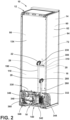
- the appliance 10 includes the machine compartment 18 which contains components of the refrigerant system 30.
- the machine compartment 18 is shown below a bottom portion of the rear panel 330, with an inner surface 332 at least partially defined by the cabinet 12.
- the external environment 24 can include the machine compartment 18.
- the machine compartment 18 can be on an opposing side of the cabinet 12 relative to the refrigerator compartment 14 and the freezer compartment 16.
- the machine compartment 18 is separated from both compartments 14, 16 via the vacuum insulated cavity 60 defined between the wrapper 62 and the liner 64.
- the machine compartment 18 operably houses various components or portions of components of the refrigerant system 30 and the appliance 10, such as a compressor 340, a condenser 342 in fluid communication with the compressor 340, a control box 344, the drain pan, refrigerant lines 346, which fluidly couple the compressor 340 to the condenser 342, and various other components, as provided herein.
- a compressor 340 a condenser 342 in fluid communication with the compressor 340
- a control box 344 the drain pan
- refrigerant lines 346 which fluidly couple the compressor 340 to the condenser 342, and various other components, as provided herein.
- the three-way valve 32 may be disposed in various locations throughout the appliance 10.
- the three-way valve 32 may be disposed in the machine compartment 18 proximate the compressor 340 and/or the condenser 342.
- the three-way valve 32 is fluidly coupled to the first evaporator 38 via the first capillary tube 202, which extends from the three-way valve 32 to the first evaporator 38.
- the three-way valve 32 is also fluidly coupled to the second evaporator 40 via the second capillary tube 264, which extends from the three-way valve 32 to the second evaporator 40. It is also generally contemplated that the three-way valve 32 may be at least partially coupled to either the first evaporator 38 and/or the second evaporator 40 via one or more expansion valves.
- the three-way valve 32 may also be fluidly coupled to and downstream from the condenser 342 or a drier 360. As the refrigerant flows through the three-way valve 32, the three-way valve 32 splits the flow of the refrigerant between the first flow path 34 and the second flow path 36, as provided herein.
- the three-way valve 32 may direct the flow of the refrigerant via one or more actuators.
- the three-way valve 32 may include an electronic actuator in communication with a controller, where the controller outputs a signal or signals to the electronic actuator to direct the flow of the refrigerant.
- the controller may include a processor configured to execute various routines stored in a memory of the controller.
- the routines may relate to the function of the refrigerant system 30, such as the three-way valve 32.
- the controller may output a signal to actuate the three-way valve 32 to direct refrigerant along the first flow path 34 or the second flow path 36 depending on various conditions.
- the controller may determine the refrigerator compartment 14 is within a temperature range of about 0 °C to about 8 °C and that the freezer compartment 16 is above a temperature of about 0 °C.
- the controller may actuate the three-way valve 32 to direct the coolant along the second flow path 36, bypassing the first evaporator 38, so the second evaporator 40 may efficiently cool the freezer compartment 16. Additionally, or alternatively, it is generally contemplated that the controller may direct refrigerant flow based on various other conditions, such as a base operating condition where refrigerant is directed along the first flow path 34, or other various conditions.
- a flow diagram depicts a refrigerant loop 350 for a thermal exchange media, referred to herein as the refrigerant, through the refrigerant system 30.
- the refrigerant is generally capable of undergoing repeated phase changes between a liquid and a gas.
- the refrigerant system 30 generally performs a refrigeration cycle that cools the refrigerator compartment 14 and the freezer compartment 16 by using the refrigerant as the thermal exchange media between the compartments 14, 16 and the external environment 24.
- the refrigerant generally flows along the refrigerant loop 350 from the compressor 340, through the condenser 342, then the drier 360, and then to the three-way valve 32, where the refrigerant is either directed along the first flow path 34 or the second flow path 36 via an actuator, and then back to the compressor 340.
- the refrigerant enters the compressor 340 as a low-pressure gas.
- the compressor 340 is configured to compress the refrigerant into a higher-pressure gas. During the compression, the refrigerant temperature increases.
- the compressor 340 is also configured to drive or circulate the refrigerant through the refrigerant system 30.
- the refrigerant exits the compressor 340 as the higher-pressure gas and enters the refrigerant line 346 which leads to the condenser 342.
- the refrigerant which is in the higher-pressure gas state, then enters the condenser 342.
- the condenser 342 is configured as a heat exchanger that may exchange heat with ambient air in the external environment 24.
- the condenser 342 condenses the refrigerant to a liquid, releasing heat.
- the drier 360 which is in fluid communication with the condenser 342 and may be coupled to the condenser 342, traps moisture, dirt, or other contaminants that may be present in the refrigerant system 30.
- the refrigerant exits the drier 360 and is directed to the three-way valve 32, where the refrigerant is either directed along the first flow path 34 or the second flow path 36.
- the refrigerant is directed from the three-way valve 32 and through the first capillary tube 202, which extends through the first pass-through 22, into the refrigerator compartment 14, and to the inlet 210 of the first evaporator 38.
- the pressure of the refrigerant drops to a lower pressure.
- the pressure drop of the refrigerant in the first capillary tube 202 is at least partially determined by the internal diameter of the first capillary tube 202.
- the refrigerant As the refrigerant enters the first evaporator 38 from the first capillary tube 202, the refrigerant experiences a pressure drop and becomes a low-pressure liquid configured to absorb heat. In use, the low-pressure liquid absorbs heat from the refrigerator compartment 14, thereby cooling the refrigerator compartment 14. Additionally, the absorption of heat from the air within the refrigerator compartment 14 by the refrigerant may be aided by the airflow generated by the first evaporator fan 150.
- the refrigerant flows from the first evaporator 38 via the first suction line 204.
- the first suction line 204 extends from the outlet 212 of the first evaporator 38, through the third pass-through 28 that extends through the mullion region 20, and couples to the second evaporator 40.
- the refrigerant once in the second evaporator 40, is in the low-pressure liquid state and is configured to absorb heat. In use, the low-pressure liquid absorbs heat from the freezer compartment 16, thereby cooling the freezer compartment 16. Additionally, the absorption of heat from the air within the freezer compartment 16 by the refrigerant may be aided by the airflow generated by the second evaporator fan 170.
- the refrigerant, in the first flow path 34 then leaves the second evaporator 40 and is directed back to the compressor 340, where the refrigerant enters the compressor 340 as a low pressure gas.
- the second flow path 36 is directed from the three-way valve 32 and through the second capillary tube 264, which bypasses the first evaporator 38 and extends through the second pass-through 26, into the freezer compartment 16, and to the inlet of the second evaporator 40.
- the pressure of the refrigerant drops to a lower pressure.
- the pressure drop of the refrigerant in the second capillary tube 264 is at least partially determined by the internal diameter of the second capillary tube 264.
- the refrigerant As the refrigerant enters the second evaporator 40 from the second capillary tube 264, the refrigerant experiences a pressure drop and becomes a low-pressure liquid configured to absorb heat. In use, the low-pressure liquid absorbs heat from the freezer compartment 16. The absorption of heat from the air within the freezer compartment 16 by the refrigerant may be aided by the airflow generated by the second evaporator fan 170. The refrigerant, after flowing through the second evaporator 40, flows back towards the compressor 340.
- the appliance 10 having the refrigerant system 30 with the first evaporator 38 and the second evaporator 40 arranged in series along the first flow path 34 and the second evaporator 40 being disposed along the second flow path 36 provides for an appliance 10 that may efficiently and selectively cool both compartments 14, 16 or the freezer compartment 16.
- the placement of the first evaporator 38 in the refrigerator compartment 14 and the second evaporator 40 in the freezer compartment 16 provides for an appliance 10 that may cool both compartments 14, 16 via the first flow path 34 and/or cool the freezer compartment 16 via the second flow path 36, bypassing the refrigerator compartment 14.
- the appliance 10 by being able to cool either both compartments 14, 16 via the first flow path 34, or the freezer compartment 16 via the second flow path 36, can either efficiently maintain an operating temperature of both compartments via the first flow path 34, or rapidly and efficiently cool the freezer compartment 16 via the second flow path 36. Additionally, the flow of the refrigerant through the first pass-through 22 and the third pass-through 28 in the first flow path 34 and the flow of the refrigerant through the second pass-through 26 in the second flow path 36 is such that the vacuum within the vacuum insulated cabinet 12 of the appliance 10 is maintained.
- the refrigerant system 30, with the first flow path 34 that extends through the first pass-through 22 and the third pass-through 28, and the second flow path 36 that extend through the second pass-through 26, can be used in various appliances.
- These appliances can include, but are not limited to, refrigerators, freezers, coolers, dishwashers, and other similar appliances and fixtures within household and commercial settings.
- the present disclosure provides for a variety of advantages.
- the placement of the first evaporator 38 within the refrigerator compartment 14 and the placement of the second evaporator 40 within the freezer compartment 16 provides for efficient cooling of the refrigerator compartment 14 and the freezer compartment 16.
- the placement of the first evaporator 38 and the second evaporator 40 in series provides for improved system balance between the first evaporator 38 and the second evaporator 40.
- the series arrangement of both evaporators 38, 40 increases a cooling load to reduce or prevent liquid refrigerant from entering the compressor 340, which reduces external condensation on the refrigerant lines 346.
- the extension of the first service line 190 and the first drain tube 220 through the first pass-through 22, and the extension of the second service line 260 and the second drain tube 270 through the second pass-through 26 reduces or limits the number of apertures through the vacuum insulated cabinet 12 to fluidly couple the first evaporator 38 and the second evaporator 40 with the other components of the refrigerant system 30.
- the first pass-through 22 and the second pass-through 26 increase the ability of the vacuum insulated cabinet 12 to maintain a vacuum.
- the extension of the first suction line 204 through the third pass-through 28 provides for the extension of the first suction line 204 through the mullion region 20, while reducing or limiting the number of apertures in the mullion region 20 and assisting in maintaining the temperature of the refrigerator compartment 14 and the freezer compartment 16. Additional benefits or advantages of using this appliance 10 may also be realized and/or achieved.
- the device disclosed herein is further summarized in the following paragraphs and is further characterized by combinations of any and all of the various aspects described herein.
- a refrigeration unit includes a cabinet that defines a refrigerator compartment, a freezer compartment, and a machine compartment.
- the cabinet includes a mullion region between the refrigerator compartment and the freezer compartment, a first pass-through therethrough providing access from an external environment to the refrigerator compartment, and a second pass-through therethrough providing access from the external environment to the freezer compartment.
- the cabinet further includes a third pass-through extending through the mullion region, and a refrigerant system.
- the refrigerant system includes a three-way valve configured to direct a refrigerant down a first flow path or a second flow path.
- the refrigerant in the first flow path flows through the first pass-through, a first evaporator, the third pass-through, and the second evaporator, and the refrigerant in the second flow path flows through the second pass-through and the second evaporator.
- a first evaporator and a second evaporator are arranged in series along a first flow path.
- a first evaporator is disposed in a refrigerator compartment and a second evaporator is disposed in a freezer compartment.
- a first evaporator fan is proximate a first evaporator and a second fan is proximate a second evaporator.
- a refrigerant system includes a compressor fluidly coupled to a first evaporator and a second evaporator, a condenser downstream of the compressor and in fluid communication with the compressor, and a drier downstream of the condenser and in fluid communication with the condenser.
- a first capillary tube upstream of a first evaporator and a second capillary tube upstream of a second evaporator The refrigerant in a first flow path flows through the first capillary tube, and the refrigerant in a second flow path flows through the second capillary tube.
- a first pass-through grommet is disposed in a first pass-through
- a second pass-through grommet is disposed in a second pass-through
- a third pass-through grommet is disposed in a third pass-through.
- the first pass-through grommet defines at least one aperture through which the first capillary tube extends
- the second pass-through grommet defines at least one aperture through which the second capillary tube extends
- a first evaporator is a first roll bond evaporator coupled to a rear wall of a refrigerator compartment.
- a refrigeration unit includes a cabinet defining a refrigerator compartment, a freezer compartment, and a machine compartment.
- the cabinet also includes a wrapper, a liner encompassed by the wrapper, a mullion region between the refrigerator compartment and the freezer compartment, a first pass-through therethrough providing access from an external environment to the refrigerator compartment, a second pass-through therethrough providing access from the external environment to the freezer compartment, a third pass-through extending through the mullion region, and a refrigerant system.
- the refrigerant system includes a first refrigerant flow path, where a refrigerant is directed through the first pass-through, a first evaporator, the third pass-through, and a second evaporator in the first refrigerant flow path.
- the refrigerant system also includes a second refrigerant flow path, where the refrigerant is directed through the second pass-through and the second evaporator in the second refrigerant flow path.
- a first service line extends through a first pass-through.
- the first service line encompasses a first capillary tube that extends from an external environment to a first evaporator.
- a first service line includes a first branch that extends towards a ceiling of a refrigerator compartment and a second branch that extends through a third pass-through and into a freezer compartment.
- the second branch at least partially encompasses a first suction line that extends from the first evaporator, through the third pass-through, and into a second evaporator.
- a first branch at least partially encompasses a first capillary tube and a first suction line.
- refrigerant is directed through a first capillary tube along a first refrigerant flow path, and the refrigerant is directed through a second capillary tube along a second refrigerant flow path, and the first capillary tube extends through a first pass-through and the second capillary tube extends through a second pass-through.
- a first fan proximate a first evaporator and a second fan proximate a second evaporator is provided.
- a first pass-through and a second pass-through are defined on a rear portion of a cabinet.
- a vacuum insulated refrigeration appliance includes a cabinet that defines a refrigerator compartment, a freezer compartment, and a mullion region between the refrigerator compartment and the freezer compartment.
- a first pass-through is defined through the mullion region, and a second pass-through extends through the cabinet and provides access from an external environment to the refrigerator compartment.
- the appliance also includes a first service line extending through the second pass-through and into the refrigerator compartment.
- the first service line includes at least one branch extending through the first pass-through and into the freezer compartment.
- the refrigerant system includes a first evaporator, a second evaporator, and a three-way valve that selectively directs a refrigerant along at least one of a first flow path through the first evaporator, the first pass-through, and the second evaporator, and a second flow path through the second evaporator.
- the first evaporator and the second evaporator are arranged in series along the first flow path.
- the refrigerant at least partially flows along the at least one branch along the first flow path.
- a third pass-through extends through a cabinet.
- the third pass-through provides access from an external environment to a freezer compartment.
- a first pass-through extends through a mullion region and provides access from a refrigerator compartment to the freezer compartment.
- a vacuum insulated refrigeration unit includes a first capillary tube upstream of a first evaporator and extending through a second pass-through and a second capillary tube upstream of a second evaporator and extending through a third pass-through.
- a refrigerant in a first flow path flows through the first capillary tube, and the refrigerant in a second flow path flows through the second capillary tube.
- a first pass-through grommet is disposed in a first pass-through that extends through a mullion region.
- a first pass-through grommet defines at least one aperture configured to permit extension of a first capillary tube through the first pass-through grommet.
- a second pass-through grommet is disposed in a second pass-through, and the second pass-through grommet defines at least one aperture configured to permit extension of a first capillary tube through the second pass-through grommet.
- a third pass-through grommet is disposed in a third pass-through. The third pass-through grommet defines at least one aperture through which a second capillary tube extends.
- the term "coupled” in all of its forms, couple, coupling, coupled, etc. generally means the joining of two components (electrical or mechanical) directly or indirectly to one another. Such joining may be stationary in nature or movable in nature. Such joining may be achieved with the two components (electrical or mechanical) and any additional intermediate members being integrally formed as a single unitary body with one another or with the two components. Such joining may be permanent in nature or may be removable or releasable in nature unless otherwise stated.
Landscapes
- Engineering & Computer Science (AREA)
- Physics & Mathematics (AREA)
- Mechanical Engineering (AREA)
- Thermal Sciences (AREA)
- General Engineering & Computer Science (AREA)
- Chemical & Material Sciences (AREA)
- Combustion & Propulsion (AREA)
- Refrigerator Housings (AREA)
Abstract
A refrigeration unit includes a cabinet (12) with a refrigerator compartment (14), a freezer compartment (16), and a machine compartment (18). The cabinet (12) includes a mullion region (20) between the refrigerator compartment (14) and the freezer compartment (16), a first pass-through (22) therethrough providing access from an external environment (24) to the refrigerator compartment (14), and a second pass-through (26) therethrough providing access from the external environment (24) to the freezer compartment (16). The cabinet (12) further includes a third pass-through (28) extending through the mullion region (20), and a refrigerant system (30). The refrigerant system (30) includes a three-way valve (32) configured to direct a refrigerant down a first flow path (34) or a second flow path (36), the refrigerant in the first flow path (34) flows through the first pass-through (22), a first evaporator (38), the third pass-through (28), and the second evaporator (40), and the refrigerant in the second flow path (36) flows through the second pass-through (26) and the second evaporator (40).
Description
- The present disclosure generally relates to a vacuum insulated structure, and more specifically, to a vacuum insulated structure with a series evaporator system.
- According to one aspect of the present disclosure, a refrigeration unit is provided that includes a cabinet that defines a refrigerator compartment, a freezer compartment, and a machine compartment. The cabinet includes a mullion region between the refrigerator compartment and the freezer compartment, a first pass-through therethrough providing access from an external environment to the refrigerator compartment, and a second pass-through therethrough providing access from the external environment to the freezer compartment. The cabinet further includes a third pass-through extending through the mullion region, and a refrigerant system. The refrigerant system includes a three-way valve configured to direct a refrigerant down a first flow path or a second flow path. The refrigerant in the first flow path flows through the first pass-through, a first evaporator, the third pass-through, and the second evaporator, and the refrigerant in the second flow path flows through the second pass-through and the second evaporator.
- According to another aspect of the present disclosure, a refrigeration unit is provided that includes a cabinet defining a refrigerator compartment, a freezer compartment, and a machine compartment. The cabinet also includes a wrapper, a liner encompassed by the wrapper, a mullion region between the refrigerator compartment and the freezer compartment, a first pass-through therethrough providing access from an external environment to the refrigerator compartment, a second pass-through therethrough providing access from the external environment to the freezer compartment, a third pass-through extending through the mullion region, and a refrigerant system. The refrigerant system includes a first refrigerant flow path, where a refrigerant is directed through the first pass-through, a first evaporator, the third pass-through, and a second evaporator in the first refrigerant flow path. The refrigerant system also includes a second refrigerant flow path, where the refrigerant is directed through the second pass-through and the second evaporator in the second refrigerant flow path.
- According to yet another aspect of the present disclosure, a vacuum insulated refrigeration appliance is provided. The vacuum insulated refrigeration appliance includes a cabinet that defines a refrigerator compartment, a freezer compartment, and a mullion region between the refrigerator compartment and the freezer compartment. A first pass-through is defined through the mullion region, and a second pass-through extends through the cabinet and provides access from an external environment to the refrigerator compartment. The appliance also includes a first service line extending through the second pass-through and into the refrigerator compartment. The second service line includes at least one branch extending through the first pass-through and into the freezer compartment. The refrigerant system includes a first evaporator, a second evaporator, and a three-way valve that selectively directs a refrigerant along at least one of a first flow path through the first evaporator, the pass-through, and the second evaporator, and a second flow path through the second evaporator. The first evaporator and the second evaporator are arranged in series along the first flow path. The refrigerant at least partially flows along the at least one branch along the first flow path.
- These and other features, advantages, and objects of the present disclosure will be further understood and appreciated by those skilled in the art by reference to the following specification, claims, and appended drawings.
- In the drawings:
-
FIG. 1 is a front perspective view of a vacuum insulated appliance, according to the present disclosure; -
FIG. 2 is a rear perspective view of a vacuum insulated appliance, according to the present disclosure; -
FIG. 3 is a front perspective view of a portion of a vacuum insulated appliance with a first pass-through to a first compartment, a second pass-through to a second compartment, and a third pass-through between the first and second compartments, according to the present disclosure; -
FIG. 4 is a front elevational view of a refrigerator compartment with a first evaporator and a first pass-through, according to the present disclosure; -
FIG. 5 is a partial top perspective view of a refrigerator compartment with a first pass-through, a second pass-through, and a first evaporator fan, according to the present disclosure; -
FIG. 6 is a front perspective view of a freezer compartment with a second evaporator and a second pass-through, according to the present disclosure; -
FIG. 7 is an enlarged, partial, cross-sectional view of a refrigeration appliance with a vacuum insulated cabinet defining a first pass-through and a third pass-through, according to the present disclosure; -
FIG. 8 is an enlarged, partial, cross-sectional view of a refrigeration appliance with a vacuum insulated cabinet, a second evaporator, and a second pass-through, according to the present disclosure; and -
FIG. 9 is a flow diagram of a refrigerant system for a refrigeration appliance, according to the present disclosure. - The components in the figures are not necessarily to scale, emphasis instead being placed upon illustrating the principles described herein.
- The present illustrated embodiments reside primarily in combinations of method steps and apparatus components related to a vacuum insulated appliance. Accordingly, the apparatus components and method steps have been represented, where appropriate, by conventional symbols in the drawings, showing only those specific details that are pertinent to understanding the embodiments of the present disclosure so as not to obscure the disclosure with details that will be readily apparent to those of ordinary skill in the art having the benefit of the description herein. Further, like numerals in the description and drawings represent like elements.
- For purposes of description herein, the terms "upper," "lower," "right," "left," "rear," "front," "vertical," "horizontal," and derivatives thereof shall relate to the disclosure as oriented in
FIG. 1 . Unless stated otherwise, the term "front" shall refer to the surface of the element closer to an intended viewer, and the term "rear" shall refer to the surface of the element further from the intended viewer. However, it is to be understood that the disclosure may assume various alternative orientations, except where expressly specified to the contrary. It is also to be understood that the specific devices and processes illustrated in the attached drawings, and described in the following specification are simply exemplary embodiments of the inventive concepts defined in the appended claims. Hence, specific dimensions and other physical characteristics relating to the embodiments disclosed herein are not to be considered as limiting, unless the claims expressly state otherwise. - The terms "including," "comprises," "comprising," or any other variation thereof, are intended to cover a non-exclusive inclusion, such that a process, method, article, or apparatus that comprises a list of elements does not include only those elements but may include other elements not expressly listed or inherent to such process, method, article, or apparatus. An element preceded by "comprises a ... " does not, without more constraints, preclude the existence of additional identical elements in the process, method, article, or apparatus that comprises the element.
- Referring to
FIGS. 1-9 ,reference numeral 10 generally designates arefrigeration appliance 10. Therefrigeration appliance 10 includes acabinet 12 that defines arefrigerator compartment 14, afreezer compartment 16, and amachine compartment 18. Amullion region 20 is defined by thecabinet 12 between therefrigerator compartment 14 and thefreezer compartment 16. A first pass-through 22 is defined by and extends through thecabinet 12 to provide access from anexternal environment 24 to therefrigerator compartment 14. A second pass-through 26 is defined by and extends through thecabinet 12 to provide access from theexternal environment 24 to thefreezer compartment 16. A third pass-through 28 is defined by thecabinet 12 and extends through themullion region 20. Therefrigeration appliance 10 also includes arefrigerant system 30. Therefrigerant system 30 includes a three-way valve 32 that is configured to selectively direct refrigerant along afirst flow path 34 and asecond flow path 36. The refrigerant in thefirst flow path 34 flows through the first pass-through 22, afirst evaporator 38, the third pass-through 28, and asecond evaporator 40. The refrigerant in thesecond flow path 36 flows through the second pass-through 26 and through thesecond evaporator 40. - Referring to
FIGS. 1-3 , theappliance 10 is illustrated as a vacuum insulated refrigeration appliance, however, it is contemplated that theappliance 10 disclosed herein may be a variety of appliances, structures, or for insulation purposes other than with anappliance 10. Therefrigeration appliance 10 is illustrated as a bottom-mount refrigerator having an insulateddoor 50 and a pull-out drawer 52, which can both have substantially similar configurations, as discussed further herein. Thecabinet 12 of the illustratedappliance 10 includes an upper compartment configured as therefrigerator compartment 14 and a lower compartment configured as thefreezer compartment 16. In this way, the refrigerator andfreezer compartments cabinet 12 can be sealed with the insulateddoor 50 and the pull-outdrawer 52, respectively. Theappliance 10 may be, for example, a bottom-mount French door refrigerator, a top-mount refrigerator, a side-by-side refrigerator, a 4-door French door refrigerator, and/or a 5-door French door refrigerator. Further, the present disclosure is not limited to refrigerators. Theappliance 10 may be, for example, a freezer, a cooler, a vacuum insulated structure, and/or other similar appliances and fixtures within household and commercial settings. - The
cabinet 12 of theappliance 10 is an insulated structure having a vacuum insulatedcavity 60 defined between awrapper 62 and aliner 64. Similarly, the insulateddoor 50, and the pull-outdrawer 52 are insulated structures having a door vacuum insulatedcavity 66 defined between adoor wrapper 68 coupled to adoor liner 70. Each of the vacuum insulatedcavities cabinet 12 and the insulateddoors cavity 60, forming a substantially continuous layer between thewrapper 62 and theliner 64. Similarly, the insulation materials substantially fill the door vacuum insulatedcavity 66, forming a substantially continuous layer between thedoor wrapper 68 and thedoor liner 70. Theinsulated cavities cabinet 12 and theinsulated doors cabinet 12 and theinsulated doors insulated cavities - An at least
partial vacuum 72 is defined within the vacuum insulatedcavities partial vacuum 72 defines a pressure differential between an exterior of theappliance 10 and the vacuum insulatedcavities wrapper 62 and theliner 64 and tends to bias thewrapper 62 and theliner 64 towards the vacuum insulatedcavity 60. The pressure differential and the inward compressive force are also exerted on both thedoor wrapper 68 and thedoor liner 70 of theinsulated doors door wrapper 68 and thedoor liner 70 towards the vacuum insulatedcavity 66 in a similar manner. - The
wrapper 62, theliner 64, thedoor wrapper 68, and thedoor liner 70 are made from a material at least partially resistant to bending, deformation, or otherwise being formed in response to an inward compressive force. These materials for thewrapper 62, thedoor wrapper 68, theliner 64, and thedoor liner 70 include, but are not limited to, metals, polymers, metal alloys, combinations thereof, and/or other similar substantially rigid materials that can be used for vacuum insulated appliances and structures. - Referring still to
FIG. 1 , the vacuum insulatedstructure 10 includes thewrapper 62, theliner 64 coupled to thewrapper 62, and atrim breaker 80 coupled to thewrapper 62 and theliner 64. Thewrapper 62 generally faces theliner 64 and at least partially encompasses theliner 64. The vacuum insulatedcavity 60 is defined in the space between thewrapper 62 and theliner 64, and thetrim breaker 80 seals the vacuum insulatedcavity 60. According to various aspects, the reduced pressure within the vacuum insulatedcavity 60 relative to theexternal environment 24 is such that a rate of heat transfer between theexternal environment 24 and therefrigerator compartment 14 and/or thefreezer compartment 16 is reduced. - Referring still to
FIG. 1 , as well asFIGS. 2-6 , thecabinet 12 defines therefrigerator compartment 14 and thefreezer compartment 16. In use, therefrigerator compartment 14 and thefreezer compartment 16 are maintained at different temperatures. For example, therefrigerator compartment 14 can be configured to maintain a temperature above about 0 °C but below the ambient temperature of theexternal environment 24, such as within a range from greater than about 0 °C to about 8 °C. Therefrigerator compartment 14 is used to maintain a food item disposed therein at a cold but not freezing temperature to prolong the usable life of the food item. Thefreezer compartment 16 can be configured to maintain a temperature that is less than or equal to about 0 °C. Thefreezer compartment 16 is used to maintain the food item disposed therein in a frozen state to prolong the usable life of the food item. Therefrigerator compartment 14 can be disposed above thefreezer compartment 16, as in the illustrated example ofFIG. 3 , although other configurations are generally contemplated. - Referring further to
FIGS. 1 ,3 , and4 , therefrigerator compartment 14 is defined by afloor 90, aceiling 92 opposing thefloor 90, afirst sidewall 94, asecond sidewall 96 opposing thefirst sidewall 94, and arear wall 98. Therefrigerator compartment 14 also defines anopening 100 that opposes therear wall 98 and operably provides access to therefrigerator compartment 14. As illustrated inFIG. 1 , theopening 100 is operably sealed from theexternal environment 24 via theinsulated door 50, which is pivotable between an opened position and a closed position. According to various aspects, theliner 64 of the vacuum insulatedstructure 10 provides thefloor 90, theceiling 92, thefirst sidewall 94, thesecond sidewall 96, and therear wall 98 of therefrigerator compartment 14. - Referring to
FIGS. 3 and6 , thefreezer compartment 16 likewise is defined by afloor 110, aceiling 112 opposing thefloor 110, afirst sidewall 114, asecond sidewall 116 opposing thefirst sidewall 114, and arear wall 118. Thefreezer compartment 16 also defines anopening 120 that opposes therear wall 118 and operably provides access to thefreezer compartment 16. As illustrated inFIG. 1 , theopening 120 to thefreezer compartment 16 is operably sealed from theexternal environment 24 via the pull-out drawer 52, which is movable between an opened position and a closed position. According to various aspects, theliner 64 of the vacuum insulatedstructure 10 provides thefloor 110, theceiling 112, thefirst sidewall 114, thesecond sidewall 116, and therear wall 118 of thefreezer compartment 16. - Referring to
FIG. 3 , themullion region 20 is defined between therefrigerator compartment 14 and thefreezer compartment 16. In such examples, thefloor 90 of therefrigerator compartment 14 may define atop section 130 of themullion region 20 and theceiling 112 of thefreezer compartment 16 may define abottom section 132 of themullion region 20. In various aspects, theliner 64 may be defined such that the vacuum insulatedcavity 60 extends from arear portion 134 of thecabinet 12, between therefrigerator compartment 14 and thefreezer compartment 16, and toward theopenings refrigerator compartment 14 and thefreezer compartment 16. - Referring to
FIGS. 3 and4 , therefrigeration appliance 10 includes therefrigerant system 30 that has thefirst evaporator 38. Thefirst evaporator 38 is disposed within therefrigerator compartment 14. Thefirst evaporator 38 is disposed adjacent theliner 64 of the vacuum insulatedstructure 10. In various examples, thefirst evaporator 38 is disposed on therear wall 98 of therefrigerator compartment 14. In the illustrated example shown inFIG. 3 , thefirst evaporator 38 is a roll bond evaporator that is coupled to therear wall 98 of therefrigerator compartment 14. Additionally, in some examples, thefirst evaporator 38 may be disposed behind acover panel 142 such that thefirst evaporator 38 is hidden when viewing therefrigerator compartment 14 through theopening 100. Thefirst evaporator 38 withdraws heat from therefrigerator compartment 14 in order to maintain the temperature of therefrigerator compartment 14 below ambient temperature. For example, thefirst evaporator 38 may withdraw heat from therefrigerator compartment 14 to maintain the temperature within therefrigerator compartment 14 at a desired temperature, such as a temperature that is from about 0 °C to about 8 °C. - Referring to
FIGS. 3-5 , therefrigerant system 30 includes a firstevaporator fan 150 proximate thefirst evaporator 38. In various aspects, the firstevaporator fan 150 may be a triple-bladed fan that is positioned proximate thefirst evaporator 38. The firstevaporator fan 150 is positioned relative to thefirst evaporator 38 such that the firstevaporator fan 150 pushes and/or pulls an airflow across thefirst evaporator 38 to assist in heat transfer between thefirst evaporator 38 and the airflow within therefrigerator compartment 14. For example, the firstevaporator fan 150 may be positioned on thefloor 90 near therear wall 98 and facing towards the opening 100 of therefrigerator compartment 14 such that an airflow is pulled down therear wall 98, across atop section 152 of thefirst evaporator 38 and then abottom section 154 of thefirst evaporator 38, and out of the firstevaporator fan 150. As the airflow flows across thefirst evaporator 38, the thermal transfer occurs such that the airflow within therefrigerator compartment 14 is cooled. - Referring to
FIGS. 6 and9 , therefrigerant system 30 includes thesecond evaporator 40. Thesecond evaporator 40 is disposed within thefreezer compartment 16. Thesecond evaporator 40 is disposed adjacent theliner 64 of the vacuum insulatedstructure 10. In various examples, thesecond evaporator 40 is disposed proximate therear wall 118 and theceiling 112 of thefreezer compartment 16 such that arear portion 160 of thesecond evaporator 40 is proximate therear wall 118 of thefreezer compartment 16 and atop section 162 of thesecond evaporator 40 abuts and/or is proximate theceiling 112 of thefreezer compartment 16. For example, thesecond evaporator 40 may be a plate-and-tube evaporator that is coupled to theceiling 112 and/orrear wall 118 of thefreezer compartment 16. - In various examples, the
second evaporator 40 may be disposed behind acover panel 164 such that thesecond evaporator 40 is hidden when viewing thefreezer compartment 16 through theopening 120. Thesecond evaporator 40 withdraws heat from thefreezer compartment 16 in order to maintain the temperature of thefreezer compartment 16 below ambient temperature. For example, thesecond evaporator 40 may withdraw heat from thefreezer compartment 16 to maintain the temperature within thefreezer compartment 16 at a desired temperature, such as a temperature that is below about 0 °C. - Referring still to
FIGS. 6 and9 , therefrigerant system 30 includes a secondevaporator fan 170 proximate thesecond evaporator 40. In various aspects, the secondevaporator fan 170 may be a triple-bladed fan that is disposed proximate thesecond evaporator 40. The secondevaporator fan 170 is positioned relative to thesecond evaporator 40 such that the secondevaporator fan 170 pushes and/or pulls an airflow across thesecond evaporator 40. For example, the secondevaporator fan 170 may be positioned on theceiling 112 proximate therear panel 118 and facing towards the opening 120 of thefreezer compartment 16 such that an airflow is pulled up along therear panel 118, across thesecond evaporator 40, and out of the secondevaporator fan 170. As the airflow flows across thesecond evaporator 40, the thermal transfer occurs such that the airflow within thefreezer compartment 16 is cooled. - Referring again to
FIGS. 2-5 and7 , the vacuum insulatedstructure 10 includes the first pass-through 22 that extends from theexternal environment 24 to therefrigerator compartment 14. The first pass-through 22 is defined by afirst wrapper aperture 180, which may be defined on arear panel 182 of thewrapper 62, and afirst liner aperture 184 defined by therear wall 118 of theliner 64 and generally aligns with thefirst wrapper aperture 180. According to various aspects, thefirst wrapper aperture 180 and thefirst liner aperture 184 may be defined such that the first pass-through 22 defines a circular shape, an oblong shape, or one of various other shapes. - The
first wrapper aperture 180 and thefirst liner aperture 184 are positioned on thewrapper 62 and theliner 64, respectively, such that passage is permitted between theexternal environment 24 and therefrigerator compartment 14. The alignment of thefirst wrapper aperture 180 and thefirst liner aperture 184 is such that various components are permitted to extend through the first pass-through 22 from theexternal environment 24 and into therefrigerator compartment 14, as provided herein. - The
refrigeration appliance 10 includes afirst service line 190. Thefirst service line 190 extends from theexternal environment 24, through the first pass-through 22, and into therefrigerator compartment 14. In some examples, thefirst service line 190 extends into therefrigerator compartment 14 and diverges. In such examples, afirst branch 192 of thefirst service line 190 extends along therear wall 98 of therefrigerator compartment 14 and towards theceiling 92 of therefrigerator compartment 14, and asecond branch 194 of thefirst service line 190 extends towards thefreezer compartment 16, as provided herein. - The
first service line 190 may include aninsulative sleeve 200 and one or more connectors and/or connection lines disposed within theinsulative sleeve 200 for fluid and/or electrical connections within theappliance 10. In the illustrated examples ofFIGS. 4 and7 , thefirst service line 190 includes a firstcapillary tube 202 and afirst suction line 204 extending within theinsulative sleeve 200. In such examples, the firstcapillary tube 202 and thefirst suction line 204 both extend along thefirst service line 190, through thefirst branch 192, and towards thefirst evaporator 38, as provided herein. According to various aspects, the firstcapillary tube 202 and thefirst suction line 204 may be positioned within thefirst service line 190 such that the firstcapillary tube 202 and thefirst suction line 204 are either proximate or distal from each other. For example, the firstcapillary tube 202 and thefirst suction line 204 may be abutting as both the firstcapillary tube 202 and thefirst suction line 204 extend along thefirst branch 192. In such examples, the close proximity may permit the transfer of thermal energy between the firstcapillary tube 202 and thefirst suction line 204. Additionally, it is generally contemplated that one or more additional lines may extend through the first pass-through 22 and into therefrigerator compartment 14. For example, an additional suction line heat exchanger line may extend through the first pass-through 22 and into therefrigerator compartment 14. - According to various aspects, the first
capillary tube 202 and thefirst suction line 204 are in fluid communication with thefirst evaporator 38. The firstcapillary tube 202 extends from the three-way valve 32 to aninlet 210 of thefirst evaporator 38. In use, the firstcapillary tube 202 carries or guides the refrigerant to thefirst evaporator 38. Thefirst suction line 204 extends from anoutlet 212 of thefirst evaporator 38, along thefirst branch 192, then thesecond branch 194, and then to thesecond evaporator 40. In use, thefirst suction line 204 carries refrigerant away from thefirst evaporator 38 and towards thesecond evaporator 40. For example, in the illustrated example ofFIG. 3 , where thefirst evaporator 38 is a roll bond evaporator, the firstcapillary tube 202 extends from the three-way valve 32, through thefirst service line 190 and along thefirst branch 192, and to theinlet 210 at a top portion of thefirst evaporator 38, and thesuction line 204 is coupled to theoutlet 212 of thefirst evaporator 38 and extends away from thefirst evaporator 38 along thefirst branch 192 and thesecond branch 192, and then towards thesecond evaporator 40. - The
refrigeration appliance 10 includes afirst drain tube 220. Thefirst drain tube 220 extends from theexternal environment 24, through the first pass-through 22, and into therefrigerator compartment 14. In some examples, thefirst drain tube 220 extends from a drain pan in theexternal environment 24, such as in themachine compartment 18, through the first pass-through 22, and up therear wall 98 of therefrigerator compartment 14 to acollection pan 224 that is disposed underneath thefirst evaporator 38. According to various aspects, thefirst drain tube 220 directs condensation that accumulates on thecollection pan 224 to the drain pan that is disposed in themachine compartment 18. - Referring further to
FIGS. 4 ,5 , and7 , therefrigeration appliance 10 includes a first pass-throughgrommet 230 disposed within the first pass-through 22. The first pass-throughgrommet 230 may have a shape that coincides with the shape of the first pass-through 22. For example, the first pass-throughgrommet 230 may have an oblong, circular, or one of other various shapes. The first pass-throughgrommet 230 may be disposed in the pass-through 22 such that arear portion 232 of the first pass-throughgrommet 230 is recessed, flush, or protruding from thewrapper 62 and afront portion 234 of the first pass-throughgrommet 230 is recessed, flush, or protruding from theliner 64. - According to various aspects, the first pass-through
grommet 230 substantially fills the first pass-through 22 to maintain an air-tight seal within the vacuum insulatedcavity 60 about the first pass-through 22. The air-tight seal defined by the first pass-throughgrommet 230 is configured to reduce or prevent the flow of air from theexternal environment 24 and into therefrigerator compartment 14. In various aspects, the first pass-throughgrommet 230 may be configured to maintain the vacuum within the vacuum insulatedcavity 60 while still permitting a connecting channel to extend through the vacuum insulatedcavity 60, as provided herein. - In various aspects, the first pass-through
grommet 230 may be oversized relative to the first pass-through 22 such that the air-tight seal may be at least partially maintained. It is also generally contemplated that the first pass-throughgrommet 230 may include components or structures that assist in at least partially maintaining the air-tight seal. For example, the first pass-throughgrommet 230 may include ribs or one or more sealing O-rings. It is further generally contemplated that the first pass-throughgrommet 230 can have a rubber or elastomeric composition and be slightly oversized relative to thefirst wrapper aperture 180 and thefirst liner aperture 184. - The
first drain tube 220 and thefirst service line 190 extend through the first pass-throughgrommet 230. The first pass-throughgrommet 230 forms an air-tight seal around thefirst drain tube 220 and thefirst service line 190. For example, the first pass-throughgrommet 230 may define a firstdrain tube aperture 240, through which thefirst drain tube 220 extends, and a firstservice line aperture 242, through which thefirst service line 190 extends. The firstdrain tube aperture 240 and the firstservice line aperture 242 may be sized slightly smaller than the outer diameters of thefirst drain tube 220 and thefirst service line 190, respectively, to assist in maintaining the air-tight seal. - According to various aspects, the air-tight fitting of the first pass-through
grommet 230 around thefirst drain tube 220 and theservice line 190 helps limit heat transfer between theexternal environment 24 and therefrigerator compartment 14 through the firstdrain tube aperture 240 and the firstservice line aperture 242. Additionally, it is generally contemplated that the first pass-throughgrommet 230 may include an insulative material encircling the firstdrain tube aperture 240 and/or the firstservice line aperture 242 to assist in limiting heat transfer between theexternal environment 24 and therefrigerator compartment 14 through the firstdrain tube aperture 240 and the firstservice line aperture 242. It is further generally contemplated that the first pass-throughgrommet 230 may include one or more apertures that permit the extension of various other components through the first pass-throughgrommet 230. For example, the first pass-throughgrommet 230 may include anaperture 244 configured to permit the extension of an electrical harness, electrical wiring, and/or other physical or electrical connectors through the first pass-throughgrommet 230 to power various features, such the firstevaporator fan 150 and various other features. - Referring to
FIGS. 2 ,3 , and6 , the vacuum insulatedstructure 10 includes the second pass-through 26 that extends from theexternal environment 24 to thefreezer compartment 16. The second pass-through 26 is defined by asecond wrapper aperture 250, which may be defined on therear panel 182 of thewrapper 62, and asecond liner aperture 252 defined on therear wall 118 of thefreezer compartment 16 and generally aligns with thesecond wrapper aperture 250. According to various aspects, thesecond wrapper aperture 250 and thesecond liner aperture 252 may be defined such that the second pass-through 26 defines a circular shape, an oblong shape, or one of various other shapes. Thesecond wrapper aperture 250 and thesecond liner aperture 252 are positioned on thewrapper 62 and theliner 64, respectively, such that passage is permitted between theexternal environment 24 and thefreezer compartment 16. According to various aspects, the alignment of thesecond wrapper aperture 250 and thesecond liner aperture 252 is such that various components are permitted to extend through the second pass-through 26 from theexternal environment 24 and into thefreezer compartment 16, as provided herein. - The
refrigeration appliance 10 includes asecond service line 260. Thesecond service line 260 extends from theexternal environment 24, through the second pass-through 26, and into thefreezer compartment 16. In some examples, thesecond service line 260 extends into thefreezer compartment 16 and then along therear wall 118 of thefreezer compartment 16 and towards theceiling 112 of thefreezer compartment 16. Additionally, it is generally contemplated that one or more additional lines may extend through the second pass-through 26 and into thefreezer compartment 16. For example, an additional suction line heat exchanger line may extend through the second pass-through 26 and into thefreezer compartment 16. - Referring to
FIGS. 2 ,6 , and8 , thesecond service line 260 may include aninsulative sleeve 262 and one or more connectors and/or connection lines disposed within theinsulative sleeve 262 for fluid and/or electrical connections within theappliance 10. In the illustrated example shown inFIG. 8 , thesecond service line 260 includes a secondcapillary tube 264 and asecond suction line 266 extending along and within theinsulative sleeve 262. In such examples, the secondcapillary tube 264 and thesecond suction line 266 may both extend along thesecond service line 260 and out of an end of thesecond service line 260. - According to various aspects, the second
capillary tube 264 and thesecond suction line 266 may be positioned within thesecond service line 260 such that the secondcapillary tube 264 and thesecond suction line 266 are either proximate or distal from each other. For example, the secondcapillary tube 264 and thesecond suction line 266 may be abutting as both the secondcapillary tube 264 and thesecond suction line 266 extend along thesecond service line 260. In such examples, the close proximity may permit transfer or thermal energy between the secondcapillary tube 264 and thesecond suction line 266. - According to various aspects, the second
capillary tube 264 and thesecond suction line 266 are in fluid communication with thesecond evaporator 40. In use, the secondcapillary tube 264 carries the refrigerant to thesecond evaporator 40 and thesuction line 266 carries the refrigerant away from thesecond evaporator 40. In some examples, the secondcapillary tube 264 may be coupled to an inlet of thesecond evaporator 40 and thesuction line 266 may be coupled to an outlet of thesecond evaporator 40. - Referring to
FIG. 6 , asecond drain tube 270, which is coupled to a collection pan, extends from theexternal environment 24, through the second pass-through 26, and into thefreezer compartment 16. In some examples, thesecond drain tube 270 extends from the drain pan in theexternal environment 24, through the second pass-through 26, and up to thesecond evaporator 40. In use, thesecond drain tube 270 directs condensation that accumulates proximate to or on thesecond evaporator 40 to the drain pan that is disposed in themachine compartment 18. - Referring to
FIGS. 2 and6 , therefrigeration appliance 10 includes a second pass-throughgrommet 280 disposed within the second pass-through 26. The second pass-throughgrommet 280 may have a shape that coincides with the shape of the second pass-through 26. For example, the second pass-throughgrommet 280 may have an oblong, circular, or one of other various shapes. The second pass-throughgrommet 280 may be disposed in the second pass-through 26 such that arear section 282 of the second pass-throughgrommet 280 is recessed, flush, or protruding from thewrapper 62 and afront section 284 of the second pass-throughgrommet 280 is recessed, flush, or protruding from theliner 64 at therear wall 118 of thefreezer compartment 16. - According to various aspects, the second pass-through
grommet 280 can help maintain an air-tight seal within the vacuum insulated structure about the second pass-through 26. The air-tight seal defined by the second pass-throughgrommet 280 is configured to reduce or prevent the flow of air from theexternal environment 24 and into thefreezer compartment 16. In various aspects, the second pass-throughgrommet 280 may be configured to maintain the vacuum within the vacuum insulatedcavity 60 while still permitting a connecting channel to extend through the vacuum insulatedcavity 60, as provided herein. - In various aspects, the second pass-through
grommet 280 may be oversized relative to the second pass-through 26 such that the air-tight seal may be at least partially maintained. It is also generally contemplated that the second pass-throughgrommet 280 may include components or structure that assists in at least partially maintaining the air-tight seal. For example, the second pass-throughgrommet 280 may include ribs or one or more sealing O-rings. It is further generally contemplated that the second pass-throughgrommet 280 can have a rubber or elastomeric composition and be slightly oversized relative to thesecond wrapper aperture 250 and thesecond liner aperture 252. - The
second drain tube 270 and thesecond service line 260 extend through the second pass-throughgrommet 280. The second pass-throughgrommet 280 forms an air-tight seal around thesecond drain tube 270 and thesecond service line 260. For example, the second pass-throughgrommet 280 may define a seconddrain tube aperture 292, through which thesecond drain tube 270 extends, and a secondservice line aperture 290, through which thesecond service line 260 extends. The seconddrain tube aperture 292 and the secondservice line aperture 290 may be sized slightly smaller than the outer diameters of thesecond drain tube 270 and thesecond service line 260, respectively, to maintain an air-tight seal. - According to various aspects, the air-tight fitting of the second pass-through
grommet 280 around thesecond drain tube 270 and thesecond service line 260 helps limit heat transfer between theexternal environment 24 and thefreezer compartment 16 through the seconddrain tube aperture 292 and the secondservice line aperture 290. Additionally, it is generally contemplated that the second pass-throughgrommet 280 may include an insulative material encircling the seconddrain tube aperture 292 and/or the secondservice line aperture 290 to assist in limiting heat transfer between theexternal environment 24 and thefreezer compartment 16 through the seconddrain tube aperture 292 and the secondservice line aperture 290. It is further generally contemplated that the second pass-throughgrommet 280 may include one or more apertures that permit the extension of various other components through the second pass-throughgrommet 280. For example, the second pass-throughgrommet 280 may include anaperture 294 configured to permit the extension of an electrical harness, electrical wiring, and/or other physical or electrical connectors through the second pass-throughgrommet 280 to power various features, such the secondevaporator fan 170 and various other features. - Referring further to
FIGS. 3 ,5 ,7 , and8 , themullion region 20 defines a third pass-through 28. The third pass-through 28 may be defined by atop aperture 302 defined by thetop section 130 of the mullion region 20 (e.g., thefloor 90 of the refrigerator compartment 14) and abottom aperture 304 defined by thebottom section 132 of the mullion region 20 (e.g., theceiling 112 of the freezer compartment 16) and generally aligns with thetop aperture 302. According to various aspects, thetop aperture 302 and thebottom aperture 304 may be defined such that the third pass-through 28 defines a circular shape, an oblong shape, or one of various other shapes. In some examples, thetop aperture 302 and thebottom aperture 304 are positioned on themullion region 20 such that passage is permitted between therefrigerator compartment 14 and thefreezer compartment 16. According to various aspects, the alignment of thetop aperture 302 and thebottom aperture 304 is such that various components are permitted to extend through the third pass-through 28 and between therefrigerator compartment 14 and thefreezer compartment 16, as provided herein. - According to various aspects, the
second branch 194 of thefirst service line 190 may extend from therefrigerator compartment 14, through the third pass-through 28, and into thefreezer compartment 16. In such aspects, thesecond branch 194 of thefirst service line 190 encompasses thefirst suction line 204, which extends from theoutlet 212 of thefirst evaporator 38, through the third pass-through 28, and to thesecond evaporator 40. - Referring to
FIGS. 3 and5 , therefrigeration appliance 10 includes a third pass-throughgrommet 310 disposed within the third pass-through 28. The third pass-throughgrommet 310 may have a shape that coincides with the shape of the third pass-through 28. For example, the third pass-throughgrommet 310 may have an oblong, circular, or one of other various shapes. The third pass-throughgrommet 310 may be disposed in the third pass-through 28 such that abottom section 312 of the third pass-throughgrommet 310 is recessed, flush, or protruding from theceiling 112 of the freezer compartment 16 (e.g., the mullion region bottom section 132) and is adjacent therear wall 118 of thefreezer compartment 16, and atop section 314 of the third pass-throughgrommet 310 is recessed, flush, or protruding from thefloor 90 of the refrigerator compartment 14 (e.g., the mullion region top section 130) and is adjacent therear wall 98 of therefrigerator compartment 14. - According to various aspects, the third pass-through
grommet 310 can help maintain an air-tight seal within the vacuum insulated structure about the third pass-through 28. The air-tight seal defined by the third pass-throughgrommet 310 is configured to reduce or prevent the flow of air between therefrigerator compartment 14 and thefreezer compartment 16. In various aspects, the first pass-throughgrommet 230 may be configured to maintain the vacuum within the vacuum insulatedcavity 60 while still permitting a connecting channel to extend through the vacuum insulatedcavity 60, as provided herein. - In various aspects, the third pass-through
grommet 310 may be oversize relative to the third pass-through 28 such that the air-tight seal may be at least partially maintained. It is also generally contemplated that the third pass-throughgrommet 310 may include components or structure that assists in at least partially maintaining the air-tight seal. For example, the third pass-throughgrommet 310 may include ribs or one or more sealing O-rings. It is further generally contemplated that the third pass-throughgrommet 310 can have a rubber or elastomeric composition and be slightly oversized relative to thetop aperture 302 and thebottom aperture 304. - The
second branch 194 of thefirst service line 190 extends through the third pass-throughgrommet 310. The third pass-throughgrommet 310 forms an air-tight seal around thesecond branch 194 of thefirst service line 190. For example, the third pass-throughgrommet 310 may define asecond branch aperture 320 through which thesecond branch 194 extends. Thesecond branch aperture 320 may be sized slightly smaller than the outer diameter of thesecond branch 194 of thefirst service line 190 to maintain an air-tight seal. - According to various aspects, the air-tight fitting of the third pass-through
grommet 310 around thesecond branch 194 of thefirst service line 190 helps limit heat transfer between theexternal environment 24 and thefreezer compartment 16 through thesecond branch aperture 320. Additionally, it is generally contemplated that the third pass-throughgrommet 310 may include an insulative material encircling thesecond branch aperture 194 to assist in limiting heat transfer between therefrigerator compartment 14 and thefreezer compartment 16 through thesecond branch aperture 320. - Referring again to
FIG. 2 , theappliance 10 includes themachine compartment 18 which contains components of therefrigerant system 30. Themachine compartment 18 is shown below a bottom portion of therear panel 330, with aninner surface 332 at least partially defined by thecabinet 12. According to various aspects, theexternal environment 24 can include themachine compartment 18. For example, themachine compartment 18 can be on an opposing side of thecabinet 12 relative to therefrigerator compartment 14 and thefreezer compartment 16. In such examples, themachine compartment 18 is separated from bothcompartments cavity 60 defined between thewrapper 62 and theliner 64. According to various aspects, themachine compartment 18 operably houses various components or portions of components of therefrigerant system 30 and theappliance 10, such as acompressor 340, acondenser 342 in fluid communication with thecompressor 340, acontrol box 344, the drain pan,refrigerant lines 346, which fluidly couple thecompressor 340 to thecondenser 342, and various other components, as provided herein. - The three-
way valve 32 may be disposed in various locations throughout theappliance 10. For example, the three-way valve 32 may be disposed in themachine compartment 18 proximate thecompressor 340 and/or thecondenser 342. The three-way valve 32 is fluidly coupled to thefirst evaporator 38 via the firstcapillary tube 202, which extends from the three-way valve 32 to thefirst evaporator 38. The three-way valve 32 is also fluidly coupled to thesecond evaporator 40 via the secondcapillary tube 264, which extends from the three-way valve 32 to thesecond evaporator 40. It is also generally contemplated that the three-way valve 32 may be at least partially coupled to either thefirst evaporator 38 and/or thesecond evaporator 40 via one or more expansion valves. - The three-
way valve 32 may also be fluidly coupled to and downstream from thecondenser 342 or a drier 360. As the refrigerant flows through the three-way valve 32, the three-way valve 32 splits the flow of the refrigerant between thefirst flow path 34 and thesecond flow path 36, as provided herein. The three-way valve 32 may direct the flow of the refrigerant via one or more actuators. For example, the three-way valve 32 may include an electronic actuator in communication with a controller, where the controller outputs a signal or signals to the electronic actuator to direct the flow of the refrigerant. - According to various aspects, the controller may include a processor configured to execute various routines stored in a memory of the controller. The routines may relate to the function of the
refrigerant system 30, such as the three-way valve 32. The controller may output a signal to actuate the three-way valve 32 to direct refrigerant along thefirst flow path 34 or thesecond flow path 36 depending on various conditions. For example, the controller may determine therefrigerator compartment 14 is within a temperature range of about 0 °C to about 8 °C and that thefreezer compartment 16 is above a temperature of about 0 °C. In such examples, the controller may actuate the three-way valve 32 to direct the coolant along thesecond flow path 36, bypassing thefirst evaporator 38, so thesecond evaporator 40 may efficiently cool thefreezer compartment 16. Additionally, or alternatively, it is generally contemplated that the controller may direct refrigerant flow based on various other conditions, such as a base operating condition where refrigerant is directed along thefirst flow path 34, or other various conditions. - As illustrated in
FIG. 9 , a flow diagram depicts arefrigerant loop 350 for a thermal exchange media, referred to herein as the refrigerant, through therefrigerant system 30. The refrigerant is generally capable of undergoing repeated phase changes between a liquid and a gas. Therefrigerant system 30 generally performs a refrigeration cycle that cools therefrigerator compartment 14 and thefreezer compartment 16 by using the refrigerant as the thermal exchange media between thecompartments external environment 24. The refrigerant generally flows along therefrigerant loop 350 from thecompressor 340, through thecondenser 342, then the drier 360, and then to the three-way valve 32, where the refrigerant is either directed along thefirst flow path 34 or thesecond flow path 36 via an actuator, and then back to thecompressor 340. - The refrigerant enters the
compressor 340 as a low-pressure gas. Thecompressor 340 is configured to compress the refrigerant into a higher-pressure gas. During the compression, the refrigerant temperature increases. Thecompressor 340 is also configured to drive or circulate the refrigerant through therefrigerant system 30. The refrigerant exits thecompressor 340 as the higher-pressure gas and enters therefrigerant line 346 which leads to thecondenser 342. - The refrigerant, which is in the higher-pressure gas state, then enters the
condenser 342. Thecondenser 342 is configured as a heat exchanger that may exchange heat with ambient air in theexternal environment 24. Thecondenser 342 condenses the refrigerant to a liquid, releasing heat. The drier 360, which is in fluid communication with thecondenser 342 and may be coupled to thecondenser 342, traps moisture, dirt, or other contaminants that may be present in therefrigerant system 30. The refrigerant exits the drier 360 and is directed to the three-way valve 32, where the refrigerant is either directed along thefirst flow path 34 or thesecond flow path 36. - In the
first flow path 34, the refrigerant is directed from the three-way valve 32 and through the firstcapillary tube 202, which extends through the first pass-through 22, into therefrigerator compartment 14, and to theinlet 210 of thefirst evaporator 38. As the refrigerant travels through the firstcapillary tube 202, the pressure of the refrigerant drops to a lower pressure. According to various aspects, the pressure drop of the refrigerant in the firstcapillary tube 202 is at least partially determined by the internal diameter of the firstcapillary tube 202. - As the refrigerant enters the
first evaporator 38 from the firstcapillary tube 202, the refrigerant experiences a pressure drop and becomes a low-pressure liquid configured to absorb heat. In use, the low-pressure liquid absorbs heat from therefrigerator compartment 14, thereby cooling therefrigerator compartment 14. Additionally, the absorption of heat from the air within therefrigerator compartment 14 by the refrigerant may be aided by the airflow generated by the firstevaporator fan 150. - Referring further to
FIG. 9 , the refrigerant flows from thefirst evaporator 38 via thefirst suction line 204. Thefirst suction line 204 extends from theoutlet 212 of thefirst evaporator 38, through the third pass-through 28 that extends through themullion region 20, and couples to thesecond evaporator 40. The refrigerant, once in thesecond evaporator 40, is in the low-pressure liquid state and is configured to absorb heat. In use, the low-pressure liquid absorbs heat from thefreezer compartment 16, thereby cooling thefreezer compartment 16. Additionally, the absorption of heat from the air within thefreezer compartment 16 by the refrigerant may be aided by the airflow generated by the secondevaporator fan 170. The refrigerant, in thefirst flow path 34, then leaves thesecond evaporator 40 and is directed back to thecompressor 340, where the refrigerant enters thecompressor 340 as a low pressure gas. - Referring further to
FIG. 9 , thesecond flow path 36 is directed from the three-way valve 32 and through the secondcapillary tube 264, which bypasses thefirst evaporator 38 and extends through the second pass-through 26, into thefreezer compartment 16, and to the inlet of thesecond evaporator 40. As the refrigerant travels through the secondcapillary tube 264, the pressure of the refrigerant drops to a lower pressure. According to various aspects, the pressure drop of the refrigerant in the secondcapillary tube 264 is at least partially determined by the internal diameter of the secondcapillary tube 264. - As the refrigerant enters the
second evaporator 40 from the secondcapillary tube 264, the refrigerant experiences a pressure drop and becomes a low-pressure liquid configured to absorb heat. In use, the low-pressure liquid absorbs heat from thefreezer compartment 16. The absorption of heat from the air within thefreezer compartment 16 by the refrigerant may be aided by the airflow generated by the secondevaporator fan 170. The refrigerant, after flowing through thesecond evaporator 40, flows back towards thecompressor 340. - Referring to
FIGS. 1-9 , theappliance 10 having therefrigerant system 30 with thefirst evaporator 38 and thesecond evaporator 40 arranged in series along thefirst flow path 34 and thesecond evaporator 40 being disposed along thesecond flow path 36 provides for anappliance 10 that may efficiently and selectively cool bothcompartments freezer compartment 16. In particular, the placement of thefirst evaporator 38 in therefrigerator compartment 14 and thesecond evaporator 40 in thefreezer compartment 16 provides for anappliance 10 that may cool bothcompartments first flow path 34 and/or cool thefreezer compartment 16 via thesecond flow path 36, bypassing therefrigerator compartment 14. Theappliance 10, by being able to cool either bothcompartments first flow path 34, or thefreezer compartment 16 via thesecond flow path 36, can either efficiently maintain an operating temperature of both compartments via thefirst flow path 34, or rapidly and efficiently cool thefreezer compartment 16 via thesecond flow path 36. Additionally, the flow of the refrigerant through the first pass-through 22 and the third pass-through 28 in thefirst flow path 34 and the flow of the refrigerant through the second pass-through 26 in thesecond flow path 36 is such that the vacuum within the vacuum insulatedcabinet 12 of theappliance 10 is maintained. - According to various examples, the
refrigerant system 30, with thefirst flow path 34 that extends through the first pass-through 22 and the third pass-through 28, and thesecond flow path 36 that extend through the second pass-through 26, can be used in various appliances. These appliances can include, but are not limited to, refrigerators, freezers, coolers, dishwashers, and other similar appliances and fixtures within household and commercial settings. - Referring further to
FIGS. 1-9 , the present disclosure provides for a variety of advantages. For example, the placement of thefirst evaporator 38 within therefrigerator compartment 14 and the placement of thesecond evaporator 40 within thefreezer compartment 16 provides for efficient cooling of therefrigerator compartment 14 and thefreezer compartment 16. Similarly, the placement of thefirst evaporator 38 and thesecond evaporator 40 in series provides for improved system balance between thefirst evaporator 38 and thesecond evaporator 40. Further, the series arrangement of bothevaporators compressor 340, which reduces external condensation on therefrigerant lines 346. - Additionally, the extension of the
first service line 190 and thefirst drain tube 220 through the first pass-through 22, and the extension of thesecond service line 260 and thesecond drain tube 270 through the second pass-through 26 reduces or limits the number of apertures through the vacuum insulatedcabinet 12 to fluidly couple thefirst evaporator 38 and thesecond evaporator 40 with the other components of therefrigerant system 30. Similarly, the first pass-through 22 and the second pass-through 26 increase the ability of the vacuum insulatedcabinet 12 to maintain a vacuum. Further, the extension of thefirst suction line 204 through the third pass-through 28 provides for the extension of thefirst suction line 204 through themullion region 20, while reducing or limiting the number of apertures in themullion region 20 and assisting in maintaining the temperature of therefrigerator compartment 14 and thefreezer compartment 16. Additional benefits or advantages of using thisappliance 10 may also be realized and/or achieved. - The device disclosed herein is further summarized in the following paragraphs and is further characterized by combinations of any and all of the various aspects described herein.
- According to an aspect of the present disclosure, a refrigeration unit is provided that includes a cabinet that defines a refrigerator compartment, a freezer compartment, and a machine compartment. The cabinet includes a mullion region between the refrigerator compartment and the freezer compartment, a first pass-through therethrough providing access from an external environment to the refrigerator compartment, and a second pass-through therethrough providing access from the external environment to the freezer compartment. The cabinet further includes a third pass-through extending through the mullion region, and a refrigerant system. The refrigerant system includes a three-way valve configured to direct a refrigerant down a first flow path or a second flow path. the refrigerant in the first flow path flows through the first pass-through, a first evaporator, the third pass-through, and the second evaporator, and the refrigerant in the second flow path flows through the second pass-through and the second evaporator.
- According to another aspect, a first evaporator and a second evaporator are arranged in series along a first flow path.
- According to another aspect, a first evaporator is disposed in a refrigerator compartment and a second evaporator is disposed in a freezer compartment.
- According to another aspect, a first evaporator fan is proximate a first evaporator and a second fan is proximate a second evaporator.
- According to another aspect, a refrigerant system includes a compressor fluidly coupled to a first evaporator and a second evaporator, a condenser downstream of the compressor and in fluid communication with the compressor, and a drier downstream of the condenser and in fluid communication with the condenser.
- According to another aspect, a first capillary tube upstream of a first evaporator and a second capillary tube upstream of a second evaporator. The refrigerant in a first flow path flows through the first capillary tube, and the refrigerant in a second flow path flows through the second capillary tube.
- According to another aspect, a first pass-through grommet is disposed in a first pass-through, a second pass-through grommet is disposed in a second pass-through, and a third pass-through grommet is disposed in a third pass-through.
- According to another aspect, the first pass-through grommet defines at least one aperture through which the first capillary tube extends, and the second pass-through grommet defines at least one aperture through which the second capillary tube extends.
- According to another aspect, a first evaporator is a first roll bond evaporator coupled to a rear wall of a refrigerator compartment.
- According to another aspect of the present disclosure, a refrigeration unit is provided that includes a cabinet defining a refrigerator compartment, a freezer compartment, and a machine compartment. The cabinet also includes a wrapper, a liner encompassed by the wrapper, a mullion region between the refrigerator compartment and the freezer compartment, a first pass-through therethrough providing access from an external environment to the refrigerator compartment, a second pass-through therethrough providing access from the external environment to the freezer compartment, a third pass-through extending through the mullion region, and a refrigerant system. The refrigerant system includes a first refrigerant flow path, where a refrigerant is directed through the first pass-through, a first evaporator, the third pass-through, and a second evaporator in the first refrigerant flow path. The refrigerant system also includes a second refrigerant flow path, where the refrigerant is directed through the second pass-through and the second evaporator in the second refrigerant flow path.
- According to another aspect, a first service line extends through a first pass-through. The first service line encompasses a first capillary tube that extends from an external environment to a first evaporator.
- According to another aspect, a first service line includes a first branch that extends towards a ceiling of a refrigerator compartment and a second branch that extends through a third pass-through and into a freezer compartment. The second branch at least partially encompasses a first suction line that extends from the first evaporator, through the third pass-through, and into a second evaporator.
- According to another aspect, a first branch at least partially encompasses a first capillary tube and a first suction line.
- According to another aspect, refrigerant is directed through a first capillary tube along a first refrigerant flow path, and the refrigerant is directed through a second capillary tube along a second refrigerant flow path, and the first capillary tube extends through a first pass-through and the second capillary tube extends through a second pass-through.
- According to another aspect, a first fan proximate a first evaporator and a second fan proximate a second evaporator is provided.
- According to another aspect, a first pass-through and a second pass-through are defined on a rear portion of a cabinet.
- According to yet another aspect of the present disclosure, a vacuum insulated refrigeration appliance is provided. The vacuum insulated refrigeration appliance includes a cabinet that defines a refrigerator compartment, a freezer compartment, and a mullion region between the refrigerator compartment and the freezer compartment. A first pass-through is defined through the mullion region, and a second pass-through extends through the cabinet and provides access from an external environment to the refrigerator compartment. The appliance also includes a first service line extending through the second pass-through and into the refrigerator compartment. The first service line includes at least one branch extending through the first pass-through and into the freezer compartment. The refrigerant system includes a first evaporator, a second evaporator, and a three-way valve that selectively directs a refrigerant along at least one of a first flow path through the first evaporator, the first pass-through, and the second evaporator, and a second flow path through the second evaporator. The first evaporator and the second evaporator are arranged in series along the first flow path. The refrigerant at least partially flows along the at least one branch along the first flow path.
- According to yet another aspect, a third pass-through extends through a cabinet. The third pass-through provides access from an external environment to a freezer compartment. A first pass-through extends through a mullion region and provides access from a refrigerator compartment to the freezer compartment.
- According to yet another aspect, a vacuum insulated refrigeration unit includes a first capillary tube upstream of a first evaporator and extending through a second pass-through and a second capillary tube upstream of a second evaporator and extending through a third pass-through. A refrigerant in a first flow path flows through the first capillary tube, and the refrigerant in a second flow path flows through the second capillary tube.
- According to another aspect, a first pass-through grommet is disposed in a first pass-through that extends through a mullion region. A first pass-through grommet defines at least one aperture configured to permit extension of a first capillary tube through the first pass-through grommet. A second pass-through grommet is disposed in a second pass-through, and the second pass-through grommet defines at least one aperture configured to permit extension of a first capillary tube through the second pass-through grommet. A third pass-through grommet is disposed in a third pass-through. The third pass-through grommet defines at least one aperture through which a second capillary tube extends.
- For purposes of this disclosure, the term "coupled" (in all of its forms, couple, coupling, coupled, etc.) generally means the joining of two components (electrical or mechanical) directly or indirectly to one another. Such joining may be stationary in nature or movable in nature. Such joining may be achieved with the two components (electrical or mechanical) and any additional intermediate members being integrally formed as a single unitary body with one another or with the two components. Such joining may be permanent in nature or may be removable or releasable in nature unless otherwise stated.
Claims (15)
- A refrigeration appliance (10), comprising:a cabinet (12) defining a refrigerator compartment (14), a freezer compartment (16), and a machine compartment (18), wherein the cabinet (12) includes:a mullion region (20) between the refrigerator compartment (14) and the freezer compartment (16);a first pass-through (22) defined through the cabinet (12) and providing access from an external environment (24) to the refrigerator compartment (14);a second pass-through (26) defined through the cabinet (12) providing access from the external environment (24) to the freezer compartment (16); anda third pass-through (28) extending through the mullion region (20); anda refrigerant system (30) including a three-way valve (32) configured to selectively direct a refrigerant along a first flow path (34) through the first pass-through (22), a first evaporator (38), the third pass-through (28), and a second evaporator (40) and along a second flow path (36) through the second pass-through (26) and the second evaporator (40).
- The refrigeration appliance (10) of claim 1, wherein the first evaporator (38) and the second evaporator (40) are arranged in a series along the first flow path (34).
- The refrigeration appliance (10) of either one of claims 1 or 2, wherein the first evaporator (38) is disposed in the refrigerator compartment (14) and the second evaporator (40) is disposed in the freezer compartment (16).
- The refrigeration appliance (10) of any one of claims 1-3, further comprising:a first evaporator fan (150) proximate the first evaporator (38); anda second evaporator fan (170) proximate the second evaporator (40).
- The refrigeration appliance (10) of any one of claims 1-4, wherein the refrigerant system (30) includes:a compressor (340) fluidly coupled to the first evaporator (38) and the second evaporator (40);a condenser (342) downstream of the compressor (340) and in fluid communication with the compressor (340); anda drier (260) downstream of the condenser (342) and in fluid communication with the condenser (340).
- The refrigeration appliance (10) of any one of claims 1-5, further comprising:a first capillary tube (202) upstream of the first evaporator (38); anda second capillary tube (264) upstream of the second evaporator (40), wherein the refrigerant in the first flow path (34) flows through the first capillary tube (202), and wherein the refrigerant in the second flow path (36) flows through the second capillary tube (264).
- The refrigeration appliance (10) of claim 6, wherein the first capillary tube (202) extends through the second pass-through (26), and wherein the second capillary tube (264) extends through the second pass-through (26).
- The refrigeration appliance (10) of either one of claims 6 or 7, further comprising:a first pass-through grommet (230) disposed in the first pass-through (22);a second pass-through grommet (280) disposed in the second pass-through (26); anda third pass-through grommet (310) disposed in the third pass-through (28).
- The refrigeration appliance (10) of claim 8, wherein the first pass-through grommet (230) defines at least one aperture (240, 242) through which the first capillary tube (202) extends, and wherein the second pass-through grommet (280) defines at least one aperture (290, 292) through which the second capillary tube (264) extends.
- The refrigeration appliance (10) of any one of claims 6-9, further comprising:
a first service line (190) extending through the first pass-through (22), the first service line (190) encompassing the first capillary tube (202) that extends from the external environment (24) to the first evaporator (38). - The refrigeration appliance (10) of claim 10, wherein the first service line (190) includes a first branch (192) that extends towards a ceiling (92) of the refrigerator compartment (14) and a second branch (194) that extends through the third pass-through (28) and into the freezer compartment (16), and wherein the second branch (194) at least partially encompasses a first suction line (204) that extends from the first evaporator (38), through the third pass-through (28), and to the second evaporator (40).
- The refrigeration appliance (10) of claim 11, wherein the first branch (192) at least partially encompasses the first capillary tube (202) and the first suction line (204).
- The refrigeration appliance (10) of any one of claims 1-12, wherein the first evaporator (38) is a first roll bond evaporator coupled to a rear wall (98) of the refrigerator compartment (14).
- The refrigeration appliance (10) of any one of claims 1-13, wherein the first pass-through (22) and the second pass-through (26) are defined by a rear portion (134) of the cabinet (12).
- The refrigeration appliance (10) of any one of claims 1-14, wherein the cabinet (12) includes:a wrapper (62); anda liner (64) coupled to the wrapper (62), and wherein the third pass-through (28) extending through the mullion region (20) provides access from the refrigerator compartment (14) to the freezer compartment (16).
Applications Claiming Priority (1)
| Application Number | Priority Date | Filing Date | Title |
|---|---|---|---|
| US18/226,322 US12474091B2 (en) | 2023-07-26 | 2023-07-26 | Vacuum insulated structure with a series evaporator |
Publications (1)
| Publication Number | Publication Date |
|---|---|
| EP4498024A1 true EP4498024A1 (en) | 2025-01-29 |
Family
ID=91969080
Family Applications (1)
| Application Number | Title | Priority Date | Filing Date |
|---|---|---|---|
| EP24190603.1A Withdrawn EP4498024A1 (en) | 2023-07-26 | 2024-07-24 | Vacuum insulated structure with a series evaporator |
Country Status (2)
| Country | Link |
|---|---|
| US (1) | US12474091B2 (en) |
| EP (1) | EP4498024A1 (en) |
Citations (4)
| Publication number | Priority date | Publication date | Assignee | Title |
|---|---|---|---|---|
| US6427463B1 (en) * | 1999-02-17 | 2002-08-06 | Tes Technology, Inc. | Methods for increasing efficiency in multiple-temperature forced-air refrigeration systems |
| EP0789206B1 (en) * | 1995-09-21 | 2003-10-01 | BSH Bosch und Siemens Hausgeräte GmbH | Refrigeration apparatus |
| WO2020207899A1 (en) * | 2019-04-08 | 2020-10-15 | BSH Hausgeräte GmbH | Refrigeration appliance and control method for a refrigeration appliance |
| EP3839387A1 (en) * | 2019-12-18 | 2021-06-23 | Whirlpool Corporation | Refrigerator |
Family Cites Families (9)
| Publication number | Priority date | Publication date | Assignee | Title |
|---|---|---|---|---|
| JP3456905B2 (en) | 1998-09-18 | 2003-10-14 | 株式会社東芝 | refrigerator |
| JP2000111230A (en) * | 1998-10-02 | 2000-04-18 | Toshiba Corp | Freezer refrigerator |
| JP3464949B2 (en) | 1999-09-21 | 2003-11-10 | 株式会社東芝 | refrigerator |
| JP2005156108A (en) | 2003-11-28 | 2005-06-16 | Matsushita Electric Ind Co Ltd | refrigerator |
| KR101095554B1 (en) | 2004-12-30 | 2011-12-19 | 삼성전자주식회사 | Operation control method of refrigerator |
| KR100687934B1 (en) | 2005-09-28 | 2007-02-27 | 삼성전자주식회사 | Refrigerator and its control method |
| KR100739195B1 (en) | 2005-12-29 | 2007-07-13 | 엘지전자 주식회사 | Refrigeration cycle in refrigerators with two evaporators for precise temperature control |
| US10544979B2 (en) | 2016-12-19 | 2020-01-28 | Whirlpool Corporation | Appliance and method of controlling the appliance |
| KR102344627B1 (en) * | 2017-07-31 | 2021-12-30 | 엘지전자 주식회사 | Refrigerator |
-
2023
- 2023-07-26 US US18/226,322 patent/US12474091B2/en active Active
-
2024
- 2024-07-24 EP EP24190603.1A patent/EP4498024A1/en not_active Withdrawn
Patent Citations (4)
| Publication number | Priority date | Publication date | Assignee | Title |
|---|---|---|---|---|
| EP0789206B1 (en) * | 1995-09-21 | 2003-10-01 | BSH Bosch und Siemens Hausgeräte GmbH | Refrigeration apparatus |
| US6427463B1 (en) * | 1999-02-17 | 2002-08-06 | Tes Technology, Inc. | Methods for increasing efficiency in multiple-temperature forced-air refrigeration systems |
| WO2020207899A1 (en) * | 2019-04-08 | 2020-10-15 | BSH Hausgeräte GmbH | Refrigeration appliance and control method for a refrigeration appliance |
| EP3839387A1 (en) * | 2019-12-18 | 2021-06-23 | Whirlpool Corporation | Refrigerator |
Also Published As
| Publication number | Publication date |
|---|---|
| US20250035344A1 (en) | 2025-01-30 |
| US12474091B2 (en) | 2025-11-18 |
Similar Documents
| Publication | Publication Date | Title |
|---|---|---|
| KR100538170B1 (en) | Refrigerator | |
| EP3751221B1 (en) | Refrigeration air supply assembly | |
| US20120060543A1 (en) | Vacuum insulator for a refrigerator appliance | |
| KR100687934B1 (en) | Refrigerator and its control method | |
| CN204043281U (en) | Refrigerator | |
| CN108224875A (en) | A kind of horizontal frostless two-temperature freezer | |
| RU2734934C2 (en) | Refrigerator and/or freezer | |
| JP5492845B2 (en) | refrigerator | |
| CN113396307B (en) | Refrigerator with direct cooling door inner chamber | |
| JP2013019598A (en) | Refrigerator | |
| EP3482145B1 (en) | Refrigeration appliance comprising a refrigerated compartment air distribution assembly | |
| US12474091B2 (en) | Vacuum insulated structure with a series evaporator | |
| EP4474739A1 (en) | Refrigeration applicance with a refrigerant line and water line extending through common pass-through of a vacuum-insulated structure | |
| US6865905B2 (en) | Refrigerator methods and apparatus | |
| JP2014112006A (en) | Refrigerator | |
| JP2020201006A (en) | refrigerator | |
| JP6123074B2 (en) | refrigerator | |
| CN102261782B (en) | Refrigerating appliance | |
| US20070074524A1 (en) | Cooling system methods and apparatus for a refrigeration device | |
| KR101132554B1 (en) | Refrigerator | |
| JP5401866B2 (en) | refrigerator | |
| US12320571B2 (en) | Thermal improvements in vis refrigerators | |
| CN220981654U (en) | Low-temperature quick-freezing refrigerator for food | |
| JP2014238212A (en) | Refrigerator | |
| CN102261783A (en) | Refrigerating appliance |
Legal Events
| Date | Code | Title | Description |
|---|---|---|---|
| PUAI | Public reference made under article 153(3) epc to a published international application that has entered the european phase |
Free format text: ORIGINAL CODE: 0009012 |
|
| STAA | Information on the status of an ep patent application or granted ep patent |
Free format text: STATUS: THE APPLICATION HAS BEEN PUBLISHED |
|
| AK | Designated contracting states |
Kind code of ref document: A1 Designated state(s): AL AT BE BG CH CY CZ DE DK EE ES FI FR GB GR HR HU IE IS IT LI LT LU LV MC ME MK MT NL NO PL PT RO RS SE SI SK SM TR |
|
| STAA | Information on the status of an ep patent application or granted ep patent |
Free format text: STATUS: THE APPLICATION HAS BEEN WITHDRAWN |
|
| 18W | Application withdrawn |
Effective date: 20250409 |