EP4497900A1 - Handle lock - Google Patents
Handle lock Download PDFInfo
- Publication number
- EP4497900A1 EP4497900A1 EP24191049.6A EP24191049A EP4497900A1 EP 4497900 A1 EP4497900 A1 EP 4497900A1 EP 24191049 A EP24191049 A EP 24191049A EP 4497900 A1 EP4497900 A1 EP 4497900A1
- Authority
- EP
- European Patent Office
- Prior art keywords
- lock
- handle
- locking
- plate
- groove
- Prior art date
- Legal status (The legal status is an assumption and is not a legal conclusion. Google has not performed a legal analysis and makes no representation as to the accuracy of the status listed.)
- Granted
Links
Images


Classifications
-
- E—FIXED CONSTRUCTIONS
- E05—LOCKS; KEYS; WINDOW OR DOOR FITTINGS; SAFES
- E05B—LOCKS; ACCESSORIES THEREFOR; HANDCUFFS
- E05B13/00—Devices preventing the key or the handle or both from being used
- E05B13/002—Devices preventing the key or the handle or both from being used locking the handle
-
- E—FIXED CONSTRUCTIONS
- E05—LOCKS; KEYS; WINDOW OR DOOR FITTINGS; SAFES
- E05B—LOCKS; ACCESSORIES THEREFOR; HANDCUFFS
- E05B13/00—Devices preventing the key or the handle or both from being used
- E05B13/10—Devices preventing the key or the handle or both from being used formed by a lock arranged in the handle
- E05B13/106—Devices preventing the key or the handle or both from being used formed by a lock arranged in the handle for handles pivoted about an axis perpendicular to the wing
- E05B13/108—Devices preventing the key or the handle or both from being used formed by a lock arranged in the handle for handles pivoted about an axis perpendicular to the wing the lock coaxial with spindle
Definitions
- the invention relates to the technical field of door locks, and more specifically, to a handle lock.
- the door lock is a commonly used door protection device to prevent illegal intrusion.
- the existing door lock locking method mainly involves setting a locking mechanism in the lock body to push the deadbolt, so that the deadbolt cannot retract from the buckle box into the lock body.
- the Chinese patent with the announcement number CN216110120U discloses a rack-type anti-locking mechanism of a door lock, which locks the outer door handle to the outer panel through a locking assembly, so that the outer door handle cannot rotate relative to the outer panel, thereby realizing the door lock.
- the locking assembly includes a square bushing, a locking cam and a locking ball matching the locking cam.
- One end of the square bushing is fixedly connected to the door outer handle, and the other end passes through the locking seat of the outer panel and is the square shafts are connected; the locking cam is rotated and set in the square shaft sleeve, and one end of the locking cam is connected to the rotating rod; when the rotating rod drives the locking came to rotate, the locking cam prompts the locking ball to squeeze outwards.
- a handle lock includes an inner base and an outer base, and an inner handle and an outer handle are respectively rotatably provided on the inner base and the outer base, and the inner handle and the outer handle are linked through a square shaft;
- the inner handle is provided with an anti-locking drive assembly, and the outer handle is provided with an anti-locking assembly.
- the anti-lock assembly includes an outer handle head connected to the outer handle, a lock plate and a linkage plate.
- the outer handle head is rotatably set in the rotation groove of the outer base.
- the lock plate is slidably set in the outer handle head.
- One end of the lock plate is provided with a locking part, and the other end is provided with a driving backrest.
- the side wall of the rotation groove is provided with a locking groove that matches the locking part.
- One end of the linkage plate is connected to the anti-lock driving assembly, and the other end is inserted into the lock plate; the anti-lock driving assembly drives the linkage The plate rotates, and the linkage plate squeezes and drives the backrest to move the lock plate toward the locking groove, and the locking part passes through the insertion groove on the outer handle head and is placed in the locking groove.
- the invention further provides that the driving backrest is in an arc shape.
- the invention further provides that: one end of the linkage plate protrudes outward toward the lock plate and is provided with an extrusion part for extruding and driving the backrest, and the extrusion part is provided with an inclined guide surface.
- the anti-locking driving assembly includes a rotating member rotatably arranged in the inner handle and an anti-locking button slidably arranged on the inner handle.
- One end of the rotating member is connected to the linkage plate, and the other end of the rotating member is connected to the linkage plate provided with threaded groove.
- the anti-lock button is provided with a compression rod that matches the threaded groove, and the compression rod drives the rotating member to drive the linkage plate to rotate by compressing the threaded groove.
- the invention further provides that: the inner handle connected to the inner handle is provided with a mounting bracket for installing the anti-lock button, and the mounting frame is provided with a sliding groove for the anti-lock button to slide.
- the invention further provides that a button window is provided on the inner handle, and the pressing part of the anti-lock button passes through the button window.
- the invention further provides that one end of the linkage plate passes through the lock plate and is connected to the lock core.
- the inner handle of the handle lock is provided with an anti-lock driving assembly
- the outer handle is provided with an anti-lock assembly
- the anti-lock assembly includes an outer handle head connected to the outer handle, a lock plate and a linkage plate , the lock plate is slidably arranged inside the outer handle; when the door lock is reverse-locked, the reverse-lock driving assembly drives the linkage plate to rotate, and the linkage plate squeezes and drives the backrest to move the lock plate toward the locking groove, and the locking portion pass through the insertion slot of the outer handle and place it in the locking slot.
- the locking part of the lock plate can be accurately inserted into the locking slot under the push of the linkage plate, so that the outer handle cannot rotate in the rotation slot of the outer base.
- the outer handle is firmly locked on the outer base, so that people outside the door cannot unlock the door lock by turning the outer handle, thereby realizing the reverse lock of the door lock;
- the reverse lock driving assembly drives the linkage plate to rotate in the reverse direction, and the linkage plate reverses
- the lock plate is driven to move, so that the lock part and the lock groove are separated, and the lock of the outer handle is released;
- the unlocking operation can be performed by turning the outer handle;
- the locking groove on the outer base of the lock plate cooperates to enable the reverse locking and unlocking operations of the door lock. Smoother and effectively avoids lagging.
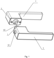
- a handle lock including an inner base 1 and an outer base 2.
- the inner base 1 and the outer base 2 are respectively provided with an inner handle 3 and an outer handle 4.
- the inner handle 3 and the outer handle 4 are rotated.
- Linkage is performed through a square shaft;
- the inner handle 3 is provided with an anti-lock driving assembly 5, and
- the outer handle 4 is provided with an anti-lock assembly 6;
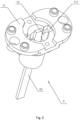
- the anti-lock assembly 6 includes an outer handle head connected to the outer handle 4 41.
- Lock plate 61 and linkage plate 62 The outer handle head 41 is rotatably disposed in the rotation groove 21 of the outer base 2.
- the lock plate 61 is slidably disposed in the outer handle head 41.
- One end of the lock plate 61 is provided with The other end of the locking part 611 is provided with a driving backrest 612; the side wall of the rotation groove 21 is provided with a locking groove 211 that matches the locking part 611, and one end of the linkage plate 62 is connected to the anti-lock driving assembly 5 , the other end is inserted into the lock plate 61; when the door lock is reverse-locked, the anti-lock driving assembly 5 drives the linkage plate 62 to rotate, and the linkage plate 62 squeezes and drives the backrest 612 to move the lock plate 61 toward the locking groove 211 , the locking portion 611 passes through the insertion slot 411 of the outer handle head 41 and is placed in the locking slot 211.
- the locking portion 611 of the locking plate 61 can be accurately inserted into the locking slot 211 under the push of the linkage plate 62.
- the anti-lock driving assembly 5 drives the linkage plate 62 to rotate in the opposite direction, and the linkage plate 62 drives the lock plate 61 to move in the opposite direction, so that the locking portion 611 is separated from the locking groove 211, and the outer handle is unlocked; the outer handle can be unlocked by rotating the outer handle. Operation; through the cooperation of the locking groove 211 on the outer base 2 of the lock plate 61, the locking and unlocking operations of the door lock are smoother, effectively avoiding jamming.
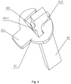
- the driving backrest 612 is in an arc shape.
- One end of the linkage plate 62 protrudes outward toward the lock plate 61 and is provided with an extrusion part 621 for extruding the driving backrest 612.
- the extrusion part 621 is provided with an inclined Guide surface 6211; when the linkage plate 62 is rotated, the extrusion part 621 will squeeze the arc-shaped driving backrest 612 under the guidance of the guide surface 6211, so that the linkage plate 62 can better drive the lock plate 61, thereby the anti-lock driving assembly 5 can be operated more effortlessly to anti-lock and unlock the door lock.
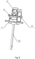
- the anti-lock driving assembly 5 includes a rotating member 51 that is rotatably installed in the inner handle 3 and an anti-lock button 52 that is slidably installed on the inner handle 3.
- One end of the rotating member 51 is connected to the linkage plate 62, and the other end is connected to the linkage plate 62.
- a threaded groove 511 is provided at one end; the anti-lock button 52 is provided with a pressing rod 521 that matches the threaded groove 511.
- the pressing rod 521 drives the rotating member 51 to drive the linkage plate 62 to rotate by pressing the threaded groove 511; through the precise cooperation of the pressing rod 521 and the threaded groove 511, the linkage plate 62 is driven, making the operation of the anti-lock button 52 more labour-saving and convenient.
- the inner handle head 31 connected to the inner handle 3 is provided with a mounting bracket 311 for installing the anti-lock button 52.
- the mounting frame 311 is provided with a sliding groove 3111 for the anti-lock button 52 to slide;
- a button window 32 is provided, and the pressing part 522 of the anti-locking button 52 passes through the button window 32; when operating the anti-locking button 52, you only need to press or push up the pressing part 522 with your fingers, so that the anti-locking button 52 can be placed in the sliding groove 3111 It slides smoothly inside; the locking or unlocking operation of the door lock is simpler and labour-saving.
- One end of the linkage plate 62 passes through the lock plate 61 and is connected to the lock cylinder 7, so that a person outside the door can insert a key into the lock cylinder 7 and drive the lock cylinder 7 to rotate, thereby driving the linkage plate 62 to rotate to achieve unlocking.
- the lock button 52 shown in Attachment Image 1 is located on the outside of the handle. If the lock button 52 is installed on the inside of the handle, it also falls within the scope of protection of this utility model.
Landscapes
- Lock And Its Accessories (AREA)
Abstract
Description
- The invention relates to the technical field of door locks, and more specifically, to a handle lock. The door lock is a commonly used door protection device to prevent illegal intrusion. The existing door lock locking method mainly involves setting a locking mechanism in the lock body to push the deadbolt, so that the deadbolt cannot retract from the buckle box into the lock body. To realize the reverse locking of the door lock; and by locking the door handle that drives the lock tongue to telescope on the door lock base, so that people cannot drive the lock tongue to telescope by turning the door handle; for example, the Chinese patent with the announcement number
CN216110120U discloses a rack-type anti-locking mechanism of a door lock, which locks the outer door handle to the outer panel through a locking assembly, so that the outer door handle cannot rotate relative to the outer panel, thereby realizing the door lock. Reverse lock, wherein the locking assembly includes a square bushing, a locking cam and a locking ball matching the locking cam. One end of the square bushing is fixedly connected to the door outer handle, and the other end passes through the locking seat of the outer panel and is the square shafts are connected; the locking cam is rotated and set in the square shaft sleeve, and one end of the locking cam is connected to the rotating rod; when the rotating rod drives the locking came to rotate, the locking cam prompts the locking ball to squeeze outwards. Make part of the locking ball pass through the ball hole of the square shaft sleeve and place it in the locking groove of the locking seat; lock the outside door handle on the locking seat, restricting the rotation of the outside door handle on the outer panel; making it impossible for people to turn the outside door handle, and thus cannot the door lock operation is performed; however, due to the locking method in which the ball is squeezed by the cam surface of the locking cam through the ball hole, and a part of the ball is placed in the locking groove of the lock seat, the door lock closing or unlocking operation often suffers from jamming, causing the door lock to not operate smoothly. - In view of the shortcomings of the existing technology, the purpose of this invention is to provide a handle lock. In order to achieve the above purpose, the invention provides the following technical solutions:
A handle lock includes an inner base and an outer base, and an inner handle and an outer handle are respectively rotatably provided on the inner base and the outer base, and the inner handle and the outer handle are linked through a square shaft; The inner handle is provided with an anti-locking drive assembly, and the outer handle is provided with an anti-locking assembly. - The anti-lock assembly includes an outer handle head connected to the outer handle, a lock plate and a linkage plate. The outer handle head is rotatably set in the rotation groove of the outer base. The lock plate is slidably set in the outer handle head. One end of the lock plate is provided with a locking part, and the other end is provided with a driving backrest.
- The side wall of the rotation groove is provided with a locking groove that matches the locking part. One end of the linkage plate is connected to the anti-lock driving assembly, and the other end is inserted into the lock plate; the anti-lock driving assembly drives the linkage The plate rotates, and the linkage plate squeezes and drives the backrest to move the lock plate toward the locking groove, and the locking part passes through the insertion groove on the outer handle head and is placed in the locking groove.
- The invention further provides that the driving backrest is in an arc shape.
- The invention further provides that: one end of the linkage plate protrudes outward toward the lock plate and is provided with an extrusion part for extruding and driving the backrest, and the extrusion part is provided with an inclined guide surface.
- The invention further provides that: the anti-locking driving assembly includes a rotating member rotatably arranged in the inner handle and an anti-locking button slidably arranged on the inner handle. One end of the rotating member is connected to the linkage plate, and the other end of the rotating member is connected to the linkage plate provided with threaded groove.
- The anti-lock button is provided with a compression rod that matches the threaded groove, and the compression rod drives the rotating member to drive the linkage plate to rotate by compressing the threaded groove.
- The invention further provides that: the inner handle connected to the inner handle is provided with a mounting bracket for installing the anti-lock button, and the mounting frame is provided with a sliding groove for the anti-lock button to slide.
- The invention further provides that a button window is provided on the inner handle, and the pressing part of the anti-lock button passes through the button window.
- The invention further provides that one end of the linkage plate passes through the lock plate and is connected to the lock core.
- Beneficial effects of the invention: the inner handle of the handle lock is provided with an anti-lock driving assembly, and the outer handle is provided with an anti-lock assembly; wherein the anti-lock assembly includes an outer handle head connected to the outer handle, a lock plate and a linkage plate , the lock plate is slidably arranged inside the outer handle; when the door lock is reverse-locked, the reverse-lock driving assembly drives the linkage plate to rotate, and the linkage plate squeezes and drives the backrest to move the lock plate toward the locking groove, and the locking portion pass through the insertion slot of the outer handle and place it in the locking slot. During this process, the locking part of the lock plate can be accurately inserted into the locking slot under the push of the linkage plate, so that the outer handle cannot rotate in the rotation slot of the outer base. The outer handle is firmly locked on the outer base, so that people outside the door cannot unlock the door lock by turning the outer handle, thereby realizing the reverse lock of the door lock; the reverse lock driving assembly drives the linkage plate to rotate in the reverse direction, and the linkage plate reverses The lock plate is driven to move, so that the lock part and the lock groove are separated, and the lock of the outer handle is released; the unlocking operation can be performed by turning the outer handle; the locking groove on the outer base of the lock plate cooperates to enable the reverse locking and unlocking operations of the door lock. Smoother and effectively avoids lagging.
-
-
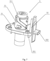
Figure 1 is a schematic structural diagram of a handle lock of the present invention; -
Figure 2 is an internal structural diagram of the outer handle of a handle lock of the present invention; -
Figure 3 is a schematic structural diagram of an anti-lock assembly of a handle lock according to the present invention; -
Figure 4 is a coordination diagram of the lock plate and the linkage plate of a handle lock according to the present invention; -
Figure 5 is a matching diagram of the lock plate and the outer base of a handle lock according to the present invention; -
Figure 6 is a coordination diagram of the anti-lock driving assembly and the linkage plate of a handle lock according to the present invention; -
Figure 7 is an installation diagram of the inner handle head of the anti-lock driving assembly of a handle lock according to the present invention; -
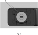
Figure 8 - a steel ball is added internally to ensure a smoother switching experience. - Explanation of reference signs: 1. Inner base; 2. Outer base; 21. Rotating groove; 211. Locking groove; 3. Inner handle; 31. Inner handle head; 311. Mounting frame; 3111. Sliding groove; 32. Button Window; 4. External handle; 41. External handle head; 411. Through slot; 5. Anti-lock drive component; 51. Rotating part; 511. Threaded groove; 52. Anti-lock button; 521. Pressure lever; 522.
Press 6. Anti-locking component; 61. Lock plate; 611. Locking part; 612. Drive backrest; 62. Linkage plate; 621. Extrusion part; 6211. Guide surface; 7. Lock cylinder. 8. steel ball - A handle lock of the present invention will be further described in detail with reference to the accompanying drawings 1 to 7.
- A handle lock, including an inner base 1 and an
outer base 2. The inner base 1 and theouter base 2 are respectively provided with aninner handle 3 and anouter handle 4. Theinner handle 3 and theouter handle 4 are rotated. Linkage is performed through a square shaft; theinner handle 3 is provided with ananti-lock driving assembly 5, and theouter handle 4 is provided with ananti-lock assembly 6; theanti-lock assembly 6 includes an outer handle head connected to theouter handle 4 41.Lock plate 61 andlinkage plate 62. Theouter handle head 41 is rotatably disposed in therotation groove 21 of theouter base 2. Thelock plate 61 is slidably disposed in theouter handle head 41. One end of thelock plate 61 is provided with The other end of the lockingpart 611 is provided with a drivingbackrest 612; the side wall of therotation groove 21 is provided with a lockinggroove 211 that matches the lockingpart 611, and one end of thelinkage plate 62 is connected to theanti-lock driving assembly 5 , the other end is inserted into thelock plate 61; when the door lock is reverse-locked, theanti-lock driving assembly 5 drives thelinkage plate 62 to rotate, and thelinkage plate 62 squeezes and drives thebackrest 612 to move thelock plate 61 toward the lockinggroove 211 , the lockingportion 611 passes through theinsertion slot 411 of theouter handle head 41 and is placed in thelocking slot 211. During this process, the lockingportion 611 of the lockingplate 61 can be accurately inserted into thelocking slot 211 under the push of thelinkage plate 62. , so that the outer handle cannot rotate in therotation groove 21 of theouter base 2, and the outer handle is firmly locked on theouter base 2, so that people outside the door cannot unlock the door lock by turning the outer handle, and realize the reverse locking of the door lock; Theanti-lock driving assembly 5 drives thelinkage plate 62 to rotate in the opposite direction, and thelinkage plate 62 drives thelock plate 61 to move in the opposite direction, so that the lockingportion 611 is separated from the lockinggroove 211, and the outer handle is unlocked; the outer handle can be unlocked by rotating the outer handle. Operation; through the cooperation of the lockinggroove 211 on theouter base 2 of thelock plate 61, the locking and unlocking operations of the door lock are smoother, effectively avoiding jamming. - The driving
backrest 612 is in an arc shape. One end of thelinkage plate 62 protrudes outward toward thelock plate 61 and is provided with anextrusion part 621 for extruding the drivingbackrest 612. Theextrusion part 621 is provided with aninclined Guide surface 6211; when thelinkage plate 62 is rotated, theextrusion part 621 will squeeze the arc-shapeddriving backrest 612 under the guidance of theguide surface 6211, so that thelinkage plate 62 can better drive thelock plate 61, thereby theanti-lock driving assembly 5 can be operated more effortlessly to anti-lock and unlock the door lock. - The
anti-lock driving assembly 5 includes a rotatingmember 51 that is rotatably installed in theinner handle 3 and ananti-lock button 52 that is slidably installed on theinner handle 3. One end of the rotatingmember 51 is connected to thelinkage plate 62, and the other end is connected to thelinkage plate 62. A threadedgroove 511 is provided at one end; theanti-lock button 52 is provided with apressing rod 521 that matches the threadedgroove 511. Thepressing rod 521 drives the rotatingmember 51 to drive thelinkage plate 62 to rotate by pressing the threadedgroove 511; through the precise cooperation of thepressing rod 521 and the threadedgroove 511, thelinkage plate 62 is driven, making the operation of theanti-lock button 52 more labour-saving and convenient. - The
inner handle head 31 connected to theinner handle 3 is provided with a mounting bracket 311 for installing theanti-lock button 52. The mounting frame 311 is provided with a sliding groove 3111 for theanti-lock button 52 to slide; A button window 32 is provided, and thepressing part 522 of theanti-locking button 52 passes through the button window 32; when operating theanti-locking button 52, you only need to press or push up thepressing part 522 with your fingers, so that theanti-locking button 52 can be placed in the sliding groove 3111 It slides smoothly inside; the locking or unlocking operation of the door lock is simpler and labour-saving. - One end of the
linkage plate 62 passes through thelock plate 61 and is connected to thelock cylinder 7, so that a person outside the door can insert a key into thelock cylinder 7 and drive thelock cylinder 7 to rotate, thereby driving thelinkage plate 62 to rotate to achieve unlocking. - The above are only the preferred embodiments of the present invention. The protection scope of the present invention is not limited to the above-mentioned embodiments. All technical solutions falling under the idea of the present invention belong to the protection scope of the present invention. It should be pointed out that for those of ordinary skill in the art, several improvements and modifications may be made without departing from the principles of the present invention, and these improvements and modifications should also be regarded as the protection scope of the present invention.
- The
lock button 52 shown in Attachment Image 1 is located on the outside of the handle. If thelock button 52 is installed on the inside of the handle, it also falls within the scope of protection of this utility model.
Claims (8)
- A handle lock, including an inner base and an outer base, the inner base and the outer base are respectively provided with inner handles and outer handles for rotation, and the inner handles and the outer handles are linked through a square shaft;
it is characterized by:the inner handle is provided with an anti-locking driving component, and the outer handle is provided with an anti-locking component; the anti-lock assembly includes an outer handle head connected to the outer handle, a lock plate and a linkage plate,the outer handle head is rotatably set in the rotation groove of the outer base, the lock plate is slidably set in the outer handle head,one end of the lock plate is provided with a locking part, and the other end is provided with a driving backrest; the side wall of the rotation groove is provided with a locking groove that matches the locking part,one end of the linkage plate is connected to the anti-lock driving assembly, and the other end is inserted into the lock plate; the anti-lock driving assembly drives the linkage the plate rotates, and the linkage plate squeezes and drives the backrest to move the lock plate toward the locking groove, and the locking part passes through the insertion groove on the outer handle head and is placed in the locking groove. - The handle lock according to the previous claim, characterized in that the driving backrest is in an arc shape.
- The handle lock according to the previous claims, characterized in that: one end of the linkage plate protrudes outward toward the lock plate and is provided with an extrusion portion for extruding and driving the backrest, the upper part is provided with a guide surface inclined.
- The handle lock according to the previous claims, characterized in that: the anti-lock driving assembly includes a rotating member rotatably provided in the inner handle and an anti-lock button slidably disposed in the inner handle, so one end of the rotating member is connected to the linkage plate, and the other end is provided with a threaded groove; the anti-lock button is provided with a compression rod that matches the threaded groove, and the compression rod drives the rotating member to drive the linkage plate to rotate by compressing the threaded groove.
- The handle lock according to the previous claims, characterized in that: the inner handle is provided with a mounting frame for installing the anti-lock button, and the mounting frame is provided with a sliding mechanism for the anti-lock button with sliding groove.
- The handle lock according to the previous claims, characterized in that: a button window is provided on the inner handle, and the pressing part of the anti-locking button passes through the button window.
- The handle lock according to the previous claims, characterized in that one end of the linkage plate passes through the lock plate and is connected to the lock core.
- The handle lock according to the previous claims, characterized in that the 3 mm thick base with a step is added to ensure the handle fits securely onto the tightly screwed area of the base and to increase the load-bearing capacity of the two legs at the connection point between the base and the handle.
Applications Claiming Priority (1)
| Application Number | Priority Date | Filing Date | Title |
|---|---|---|---|
| CN202321978811.XU CN220522264U (en) | 2023-07-26 | 2023-07-26 | a handle lock |
Publications (3)
| Publication Number | Publication Date |
|---|---|
| EP4497900A1 true EP4497900A1 (en) | 2025-01-29 |
| EP4497900B1 EP4497900B1 (en) | 2026-02-11 |
| EP4497900C0 EP4497900C0 (en) | 2026-02-11 |
Family
ID=89937657
Family Applications (1)
| Application Number | Title | Priority Date | Filing Date |
|---|---|---|---|
| EP24191049.6A Active EP4497900B1 (en) | 2023-07-26 | 2024-07-26 | Handle lock |
Country Status (2)
| Country | Link |
|---|---|
| EP (1) | EP4497900B1 (en) |
| CN (1) | CN220522264U (en) |
Citations (4)
| Publication number | Priority date | Publication date | Assignee | Title |
|---|---|---|---|---|
| US6470721B2 (en) * | 2001-01-05 | 2002-10-29 | Taiwan Fu Hsing Industrial Co., Ltd. | Strength reinforcing structure of a lock outer handle |
| US6543265B1 (en) * | 2001-11-15 | 2003-04-08 | Fang-Yi Fan | Door lock-and-handle assembly |
| US20070051145A1 (en) * | 2005-09-02 | 2007-03-08 | Ez Trend Technology Co.,Ltd | Electric lock |
| CN216110120U (en) | 2021-09-30 | 2022-03-22 | 温州市卡宾斯智能科技有限公司 | Rack type back locking mechanism of door lock |
-
2023
- 2023-07-26 CN CN202321978811.XU patent/CN220522264U/en active Active
-
2024
- 2024-07-26 EP EP24191049.6A patent/EP4497900B1/en active Active
Patent Citations (4)
| Publication number | Priority date | Publication date | Assignee | Title |
|---|---|---|---|---|
| US6470721B2 (en) * | 2001-01-05 | 2002-10-29 | Taiwan Fu Hsing Industrial Co., Ltd. | Strength reinforcing structure of a lock outer handle |
| US6543265B1 (en) * | 2001-11-15 | 2003-04-08 | Fang-Yi Fan | Door lock-and-handle assembly |
| US20070051145A1 (en) * | 2005-09-02 | 2007-03-08 | Ez Trend Technology Co.,Ltd | Electric lock |
| CN216110120U (en) | 2021-09-30 | 2022-03-22 | 温州市卡宾斯智能科技有限公司 | Rack type back locking mechanism of door lock |
Also Published As
| Publication number | Publication date |
|---|---|
| EP4497900B1 (en) | 2026-02-11 |
| EP4497900C0 (en) | 2026-02-11 |
| CN220522264U (en) | 2024-02-23 |
Similar Documents
| Publication | Publication Date | Title |
|---|---|---|
| US5809815A (en) | Lever lock assembly with a burglar-proof exterior handle | |
| EP2985397A1 (en) | Mortise lock | |
| CN110616968A (en) | Full-automatic lock | |
| US4799718A (en) | Sabotage-proof lock device with elbow-shaped latches | |
| US4867491A (en) | Locking device for doors or windows including means for locking the square-sectioned handle-bar of the handle | |
| CN219528674U (en) | Handle door lock | |
| CN109681034A (en) | A kind of smart lock lock body | |
| CN211874180U (en) | A multi-point door lock structure | |
| EP4497900B1 (en) | Handle lock | |
| CN217353893U (en) | Novel ecological door lock | |
| CN218509221U (en) | Portable door lock | |
| CN219431573U (en) | Antitheft lock with emergency escape capability | |
| CN216043101U (en) | Worm type back locking mechanism of door lock | |
| GB2324331A (en) | Window lock automatically releasable on opening of the window | |
| CN223190194U (en) | Counter-locking mechanism of ecological door lock | |
| KR102504484B1 (en) | Deadbolt drive assembly for door lock mortise | |
| CN216043102U (en) | Gear type back locking mechanism of door lock | |
| CN220059205U (en) | Handle lock | |
| CN222501301U (en) | Extremely simple door lock | |
| CN219887779U (en) | Ecological door lock | |
| CN224228387U (en) | Back-locking structure of handle lock | |
| CN223621382U (en) | A double-leaf door handle lock assembly | |
| CN223089065U (en) | An ecological door lock | |
| CN218862307U (en) | Double-opening door lock device and cabinet door | |
| CN221481666U (en) | Automatic electronic lock |
Legal Events
| Date | Code | Title | Description |
|---|---|---|---|
| PUAI | Public reference made under article 153(3) epc to a published international application that has entered the european phase |
Free format text: ORIGINAL CODE: 0009012 |
|
| STAA | Information on the status of an ep patent application or granted ep patent |
Free format text: STATUS: THE APPLICATION HAS BEEN PUBLISHED |
|
| AK | Designated contracting states |
Kind code of ref document: A1 Designated state(s): AL AT BE BG CH CY CZ DE DK EE ES FI FR GB GR HR HU IE IS IT LI LT LU LV MC ME MK MT NL NO PL PT RO RS SE SI SK SM TR |
|
| STAA | Information on the status of an ep patent application or granted ep patent |
Free format text: STATUS: REQUEST FOR EXAMINATION WAS MADE |
|
| 17P | Request for examination filed |
Effective date: 20250728 |
|
| GRAP | Despatch of communication of intention to grant a patent |
Free format text: ORIGINAL CODE: EPIDOSNIGR1 |
|
| STAA | Information on the status of an ep patent application or granted ep patent |
Free format text: STATUS: GRANT OF PATENT IS INTENDED |
|
| RIC1 | Information provided on ipc code assigned before grant |
Ipc: E05B 13/00 20060101AFI20250829BHEP Ipc: E05B 13/10 20060101ALI20250829BHEP |
|
| INTG | Intention to grant announced |
Effective date: 20251002 |
|
| GRAS | Grant fee paid |
Free format text: ORIGINAL CODE: EPIDOSNIGR3 |
|
| GRAA | (expected) grant |
Free format text: ORIGINAL CODE: 0009210 |
|
| STAA | Information on the status of an ep patent application or granted ep patent |
Free format text: STATUS: THE PATENT HAS BEEN GRANTED |
|
| AK | Designated contracting states |
Kind code of ref document: B1 Designated state(s): AL AT BE BG CH CY CZ DE DK EE ES FI FR GB GR HR HU IE IS IT LI LT LU LV MC ME MK MT NL NO PL PT RO RS SE SI SK SM TR |
|
| REG | Reference to a national code |
Ref country code: CH Ref legal event code: F10 Free format text: ST27 STATUS EVENT CODE: U-0-0-F10-F00 (AS PROVIDED BY THE NATIONAL OFFICE) Effective date: 20260211 Ref country code: GB Ref legal event code: FG4D |
|
| REG | Reference to a national code |
Ref country code: DE Ref legal event code: R096 Ref document number: 602024002498 Country of ref document: DE |
|
| REG | Reference to a national code |
Ref country code: IE Ref legal event code: FG4D |
|
| U01 | Request for unitary effect filed |
Effective date: 20260305 |
|
| U07 | Unitary effect registered |
Designated state(s): AT BE BG DE DK EE FI FR IT LT LU LV MT NL PT RO SE SI Effective date: 20260311 |
|
| PG25 | Lapsed in a contracting state [announced via postgrant information from national office to epo] |
Ref country code: RS Free format text: LAPSE BECAUSE OF FAILURE TO SUBMIT A TRANSLATION OF THE DESCRIPTION OR TO PAY THE FEE WITHIN THE PRESCRIBED TIME-LIMIT Effective date: 20260511 |
|
| PG25 | Lapsed in a contracting state [announced via postgrant information from national office to epo] |
Ref country code: ES Free format text: LAPSE BECAUSE OF FAILURE TO SUBMIT A TRANSLATION OF THE DESCRIPTION OR TO PAY THE FEE WITHIN THE PRESCRIBED TIME-LIMIT Effective date: 20260211 |
|
| PG25 | Lapsed in a contracting state [announced via postgrant information from national office to epo] |
Ref country code: PL Free format text: LAPSE BECAUSE OF FAILURE TO SUBMIT A TRANSLATION OF THE DESCRIPTION OR TO PAY THE FEE WITHIN THE PRESCRIBED TIME-LIMIT Effective date: 20260211 |
|
| PG25 | Lapsed in a contracting state [announced via postgrant information from national office to epo] |
Ref country code: GR Free format text: LAPSE BECAUSE OF FAILURE TO SUBMIT A TRANSLATION OF THE DESCRIPTION OR TO PAY THE FEE WITHIN THE PRESCRIBED TIME-LIMIT Effective date: 20260512 |
|
| PG25 | Lapsed in a contracting state [announced via postgrant information from national office to epo] |
Ref country code: NO Free format text: LAPSE BECAUSE OF FAILURE TO SUBMIT A TRANSLATION OF THE DESCRIPTION OR TO PAY THE FEE WITHIN THE PRESCRIBED TIME-LIMIT Effective date: 20260511 |
|
| PG25 | Lapsed in a contracting state [announced via postgrant information from national office to epo] |
Ref country code: HR Free format text: LAPSE BECAUSE OF FAILURE TO SUBMIT A TRANSLATION OF THE DESCRIPTION OR TO PAY THE FEE WITHIN THE PRESCRIBED TIME-LIMIT Effective date: 20260211 |
|
| PG25 | Lapsed in a contracting state [announced via postgrant information from national office to epo] |
Ref country code: IS Free format text: LAPSE BECAUSE OF FAILURE TO SUBMIT A TRANSLATION OF THE DESCRIPTION OR TO PAY THE FEE WITHIN THE PRESCRIBED TIME-LIMIT Effective date: 20260611 |
|
| REG | Reference to a national code |
Ref country code: SK Ref legal event code: T3 Ref document number: E 48678 Country of ref document: SK |