EP4497883A1 - Unterirdische regenwasserspeichervorrichtung - Google Patents
Unterirdische regenwasserspeichervorrichtung Download PDFInfo
- Publication number
- EP4497883A1 EP4497883A1 EP24190957.1A EP24190957A EP4497883A1 EP 4497883 A1 EP4497883 A1 EP 4497883A1 EP 24190957 A EP24190957 A EP 24190957A EP 4497883 A1 EP4497883 A1 EP 4497883A1
- Authority
- EP
- European Patent Office
- Prior art keywords
- rainwater
- crate
- base wall
- supports
- wall section
- Prior art date
- Legal status (The legal status is an assumption and is not a legal conclusion. Google has not performed a legal analysis and makes no representation as to the accuracy of the status listed.)
- Pending
Links
Images


Classifications
-
- E—FIXED CONSTRUCTIONS
- E03—WATER SUPPLY; SEWERAGE
- E03F—SEWERS; CESSPOOLS
- E03F1/00—Methods, systems, or installations for draining-off sewage or storm water
- E03F1/002—Methods, systems, or installations for draining-off sewage or storm water with disposal into the ground, e.g. via dry wells
- E03F1/005—Methods, systems, or installations for draining-off sewage or storm water with disposal into the ground, e.g. via dry wells via box-shaped elements
-
- Y—GENERAL TAGGING OF NEW TECHNOLOGICAL DEVELOPMENTS; GENERAL TAGGING OF CROSS-SECTIONAL TECHNOLOGIES SPANNING OVER SEVERAL SECTIONS OF THE IPC; TECHNICAL SUBJECTS COVERED BY FORMER USPC CROSS-REFERENCE ART COLLECTIONS [XRACs] AND DIGESTS
- Y02—TECHNOLOGIES OR APPLICATIONS FOR MITIGATION OR ADAPTATION AGAINST CLIMATE CHANGE
- Y02A—TECHNOLOGIES FOR ADAPTATION TO CLIMATE CHANGE
- Y02A20/00—Water conservation; Efficient water supply; Efficient water use
- Y02A20/108—Rainwater harvesting
Definitions
- the present invention relates to a rainwater crate for building a subterranean rainwater storage device.
- a rainwater storage device comprises an inner storage body that is built up with multiple rainwater crates. The inner storage body is enclosed by an outer layer to define a rainwater storage device volume.
- Such subterranean rainwater storage device is known from European patent publication EP 4,159,944 A1 and installed for the storage and buffering of large amounts of rain water during rain fall that indirectly or directly drains into the rainwater storage device.
- the terrain above the rainwater storage device can be implemented as any infrastructure or urban area, such as a park, a sport area or a road.
- a known inner storage body comprises multiple plastic rainwater crates that are stacked onto each other.
- the rainwater crates are relatively voluminous and lightweight, and are therefore preferably supplied in packs wherein the rainwater crates are at least partially inserted into each other or nested to save transport space.
- a compromise was found between the total weight and the outer dimensions both in use and during transport.
- WO2011/042415A1 describes a drainage body which has two substantially identically formed surface-area units, namely a base unit and a substantially identically formed cover unit, which can be connected to one another in an installed state via spacer elements.
- IT BO20110633A1 describes an infiltration block for (rainwater) water, and a modular infiltration system for the disposal of rainwater comprising a plurality of said blocks.
- aspects of the present disclosure aim to solve at least one of the above-mentioned problems and/or disadvantages and to provide at least one or more of the advantages described below. It may be an object of the present invention to provide a rainwater storage device having rainwater crates that can be inspected by inspection robots while taking the need for carrying vertical loads and stacking into account. Furthermore, it may be an object of the present invention to provide rainwater crates suitable for building a rainwater storage device, which are easy to handle, easy to connect and allow nesting of crates for transport.
- a rainwater crate a method for stacking a rainwater crate, a set of rainwater crates, a subterranean rainwater storage device, a method for building a set and a method for building a subterranean rainwater storage device according to the independent claims.
- Embodiments are defined by the dependent claims.
- the present invention relates to a first rainwater crate that is configured for cooperation with an identical second rainwater crate for building a subterranean rainwater storage device.
- the first rainwater crate comprises a base wall having a first base wall section, a second base wall section and a third base wall section that are consecutive to each other in a first direction of the base wall, i.e. the wall sections are positioned next to each other without any gaps or interruptions between them.
- a plurality of supports project in the same direction from the base wall, preferably perpendicular to the base wall.
- Each of the first and second base wall sections is adjacent to the third base wall section and comprises one or more of the supports.
- the supports in the first base wall section have a first distribution over the first base wall section and the supports in the second base wall section have a second distribution over the second base wall section, wherein each of the first and second distribution comprises: a first set of supports comprising at least one support having a distal end provided with a male connector, and a second set of supports comprising at least one support having a distal end provided with a female connector.
- the distal end of the first set of supports may be provided with a mixed male/female connector in a predetermined pattern and the distal end of the second set of supports may be provided with a mixed female/male connector in a mirrored pattern.
- the distal end of the first set of supports is provided with a single male connector.
- Each of the first and second distribution further comprises a third set of supports in between the first and second sets consisting of one or more supports having a distal end without a connector.
- the presence of the third set of supports provides further support which allows the rainwater crate to carry higher vertical loads while due to the lack of male connectors the stackability is not influenced.
- the present invention relates to the first rainwater crate as described above, wherein the distribution of supports with a male connector exhibit 180° rotational symmetry with respect to a notional rotational axis that extends perpendicular to and through the center of the base wall.
- the first and second distribution exhibit 180° rotational symmetry with respect to a notional rotational axis that extends perpendicular to and through the center of the base wall.
- the stacking of identical rainwater crates is allowed in two orientations that are 180° apart and being prevented in the intermediate orientations. As such, the notional planes that extend perpendicular to the respective third base wall section are aligned when stacked. Allowing for the creation of an inspection passage between the third base wall section of the stacked rainwater crates.
- the first and second distribution may only comprise supports with a male connector in corners of the rainwater crate. Then, the first and second distribution alternatively comprises supports with a male connector and supports with a female connector in the corners of the rainwater crate. The remainder of the supports may have no connector or female connector.
- the present invention relates to the first rainwater crate as described above, wherein the third base wall section is free of supports such that free space is provided between the supports of the first base wall section and the supports of the second base wall section. Therefore, the maximal height of the third base wall section may be at most 5 times the average base wall section or the maximal height of the third base wall section may be less than half, one third, one fifth or one tenth of the average height of a support. Preferable the maximal height of the third base wall is in range of approximately 5-50 mm, preferably 20-40 mm, and more preferably around 30 mm.
- the present invention relates to the first rainwater crate as described above, wherein the at least one support having a distal end comprising a male connector in the first set of supports are supports having a single connector which is male and wherein the at least one support having a distal end comprising a female connector in the second set of supports are supports having a single connector which is female.
- the present invention relates to the first rainwater crate as described above, wherein the base wall has a square circumference and wherein the first base wall section, a second base wall section and a third base wall section each have a rectangular circumference.
- the first base wall section, a second base wall section and a third base wall section each having lengths L1, L2 and L3 respectively and in the first direction of the base wall widths W1, W2 and W3 respectively.
- the lengths of the base wall sections L1, L2 and L3 are equal, as shown in Figure 1C .
- the present invention relates to the first rainwater crate as described above, wherein the supports are hollow and have an entrance opening at the proximal end of the supports with the base wall.
- the present invention relates to the first rainwater crate as described above, wherein the first rainwater crate is configured to have in cooperation with the second rainwater crate a transport position and an installation position, wherein in the transport position the first rainwater crate is positioned straight above the second rainwater crate while the supports are nested into each other via the entrance openings, and wherein in the installation position the first rainwater crate is unnested from the second rainwater crate and rotated 180° over a notional first axis that lies in the plane of the base wall and extends through the center of the base wall in the first direction of the first rainwater crate.
- the present invention relates to the first rainwater crate as described above, wherein the first set consists of one or more supports having a distal end with a male connector and the second set consists of one or more supports having a distal end with a female connector.
- the present invention relates to the first rainwater crate as described above, wherein the supports are arranged in rows in the first direction of the base wall and/or in columns in a second direction of the base wall. In a further embodiment, the present invention relates to the first rainwater crate as described above, wherein an uneven number of supports are provided in each column.
- the present invention relates to the first rainwater crate as described above, wherein the number of supports in each of the first and second sets is at least twice the number of supports in the third set.
- the present invention relates to the first rainwater crate as described above, wherein the supports in the first base wall section and/or the supports in the second base wall section are equidistantly spaced.
- Equidistantly spaced refers to a distribution or arrangement where the intervals or distances between the adjacent supports points or objects are equal.
- distribution in the first base wall section corresponds to the distribution in the second base wall section.
- any distribution or arrangement in which the distribution male supports in the first base wall section and the distribution female supports in the second base wall section, and vice versa, may be used.
- the present invention relates to the first rainwater crate as described above, wherein the sum of the width of the first and second base wall section is larger than the width of the third base wall section.
- the present invention relates to the first rainwater crate as described above, wherein the sum of the width of the first and third base wall section is less than the width of the second base wall section.
- the present invention relates to the first rainwater crate as described above, wherein the third base wall section is configured as a driving surface for robotic vehicles.
- the third base wall section may be provided with a circular punch plate, a tread plate, or any other kind of traction grip plate adapted for use to be placed under a vehicle wheel to enable the wheel to obtain traction.
- the traction grip plate is integrated in the third base wall section.
- the present invention relates to the first rainwater crate as described above, further comprising at least one sedimentation channel mounted in the third base wall section, wherein the at least one sedimentation channel extends in the second direction of the base wall, and wherein the at least one sedimentation channel has a closed floor.
- the sedimentation channel extends in the first direction of the base wall between a first and second sedimentation wall, wherein the distance between a first and second sedimentation wall in the first direction varies along the second direction.
- the sedimentation channel may have at least two relatively narrow sections alternating with at least two relatively wide sections over the width (in the second direction) of the base wall, wherein the length (in the first direction) of each narrow section is smaller than the length of the wide sections, preferably the sedimentation channel has at least three relatively narrow sections.
- the narrow section may extend in the first direction from nearby a support of the first distribution to nearby a support of the second distribution
- the wide section may extend in the first direction from between two supports of the first distribution to between two supports of the second distribution.
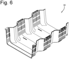
- the sedimentation channel has an outer shape and outer dimensions such that the sedimentation channel mates with the supports, as shown in Figure 6 .
- the present invention relates to the first rainwater crate as described above, wherein the male connector is a plug and the female connector is a socket.
- the present invention relates to the first rainwater crate as described above, further comprising a plurality of coupling means located on at least one edge of the base wall suitable for coupling with a side wall having complementary coupling means.
- the present invention relates to the first rainwater crate as described above, wherein the supports comprise a circumferential wall, with preferably a constant wall height, that at the proximal side merges into the base wall.
- the supports possesses a greater level of resilience and durability compared to beveled alternatives.
- the present invention relates to a method for stacking a first rainwater crate in a second rainwater crate identical to the first rainwater crate, wherein the supports are hollow and have an entrance opening at the proximal end of the supports with the base wall, and wherein the supports in the second rainwater crate respectively enter the entrance opening of the supports in the first rainwater crate.
- the present invention relates to a set comprising a first rainwater crate and a second rainwater crate according to the invention.
- the distal ends of the supports in the first rainwater crate are respectively in contact with the distal ends of the supports in the second rainwater crate, and the third base wall sections of the first and second rainwater crates together form the opposite walls of a through channel, preferably an inspection channel and/or a sedimentation channel.
- the present invention relates to a subterranean rainwater storage device comprising an inner storage body, a plurality of coupling means and an outer layer around the inner storage body that together define a rainwater storage device volume, wherein the inner storage body comprises a plurality of sets according to the invention.
- the outer layer comprises at least one side wall connecting to the first and second rainwater crates in some of the sets, wherein the coupling means couple adjacent sets to each other.
- the present invention relates to a method for building a set according to the inventions, comprising: supplying a plurality of rainwater crates, preferably a plurality of stacked rainwater crates according to the invention, taking a first rainwater crate, preferably from the stack, rotating the first rainwater crate and placing the first rainwater crate on the second rainwater crate, such that the distal ends of the supports in the first rainwater crate are respectively in contact with the distal ends of the supports in the second rainwater crate.
- the present invention relates to a method for building an inversed set comprising a first rainwater crate and a second rainwater crate according to the invention.
- the method comprises supplying a plurality of rainwater crates, preferably a plurality of stacked rainwater crates according to the invention, taking a first rainwater crate, preferably from the stack, inverting the first rainwater crate and placing the second rainwater crate on the first rainwater crate, such that the base wall of the first rainwater crate is in contact with the base wall of the second rainwater crate and that the supports on the base walls are aligned.
- the present invention relates to a method for building a subterranean rainwater storage device according to the invention, comprising: supplying a plurality of rainwater crates, repeatedly taking a rainwater crate and placing a plurality of said rainwater crates in a row, repeatedly taking a rainwater crate and placing the same on a rainwater crate in the row such that the distal ends of the supports in the first rainwater crate are respectively in contact with the distal ends of the supports in the second rainwater crate.
- the present invention relates to the method as described above, further comprising coupling the adjacent rainwater crates in the row to each other. In an embodiment, the present invention relates to the method as described above, further comprising mounting one or more side walls on the rainwater crates.
- top, bottom, back, front and the like in the description and the claims are used for descriptive purposes and not necessarily for describing relative positions. The terms so used are interchangeable under appropriate circumstances and the embodiments of the invention described herein can operate in other orientations than described or illustrated herein.
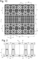
- FIGS 1A, 1B and 1C show a rainwater crate 51 configured for cooperation with an identical rainwater crate 52 for building a subterranean rainwater storage device (shown in Figures 2 , 3A and 3B ).
- the rainwater crate comprises a base wall 53 and a plurality of supports 58, 59, 60 projecting from the base wall.
- the base wall 53 has a pair of parallel longitudinal edges 54 and a pair of parallel transverse edges 55 that extend orthogonal to each other to define a rectangular circumference of the rainwater crate 51, in this example a square circumference.
- the transverse edges 55 have a transverse width W4 in a width direction W and the longitudinal edges 54 have a longitudinal length L4 in a length direction L that is a number of times to the transverse width W4, in this example equal to the transverse width W4.
- the longitudinal length L4 is in the range of 0.4 - 1.2 meter, preferably approximately 0,8 meter.
- the base wall 53 has any configuration that allows the rainwater crate 51 to carry vertical loads, such as a solid unity or a water permeable grid or grating.
- the supports 58, 59, 60 project parallel to each other and all in the same direction from the base wall 53, having their centre lines orthogonal to the base wall 53.
- Each support 58, 59, 60 comprises a circumferential wall 70 with a constant wall thickness that at the proximal side merges into the base wall 53 where it defines an entrance opening 72, and that tapers towards the distal end where it in this example merges into a bottom wall 73.
- the circumferential wall 70 has any configuration that allows the rainwater crate 51 to carry vertical loads, such as a solid unity or a water permeable grid or grating as schematically indicated for a small part thereof.
- the base wall 53 defines first support areas around the first entrance openings 72 that are adjacent to the first entrance openings 72.
- the base wall 53 comprises a first base wall section I and a second base wall section II that are notionally divided by an intermediate third base wall section III halfway the longitudinal length L4 as indicated by broken lines 56, 57, giving the first base wall section I and the second base wall section II both an equal notional square circumference, as shown in Figure 1 C.
- the supports are distributed over the first base wall section I in a first distribution and over the second base wall section II in a second distribution.
- the first distribution comprises a number of male supports 59, a number of female supports 60 and a number of neutral supports 58 therebetween.
- Each male support 59 is provided with a male connector 74 that projects from the bottom wall 73 and each female supports 60 is provided with a female connector 75 that is recessed from the bottom wall 73.
- the male connector has an outer shape and outer dimensions such that the male connector mates with and tightly fits inside the female connector 60.
- the bottom wall 73 of the neutral supports 58 are substantially flat.
- the rainwater crate 51 is asymmetric with respect to a notional first plane S1 that extends through the middle and transverse to the base wall 53, as shown in Figure 2 .
- the rainwater crate 51 is 180° rotational-symmetric with respect to a notional axis R that extends through the middle and transverse to the base wall 53, as shown in Figure 1B .
- the first base wall section I comprises two columns of hollow supports 58, 59, 60 having their centres at equal longitudinal intermediate distances L5 and equal transverse intermediate distances W5 from each other in a rectangular configuration.
- the longitudinal intermediate distances L5 are equal to the transverse intermediate distances W5.
- the columns comprise two rows of male support and two rows of female supports that are divided by a row of neutral supports.
- the second base wall section II comprises ten hollow supports two columns of hollow supports 60 having their centres at equal longitudinal intermediate distances L6 and equal transverse intermediate distances W6 from each other in a rectangular configuration.
- the longitudinal intermediate distances L6 are equal to the transverse intermediate distances W6.
- the longitudinal intermediate distances L6 are equal to the longitudinal intermediate distances L5.
- the columns comprise two rows of male support and two rows of female supports that are divided by a row of neutral supports.
- the third base wall section III is free of supports.
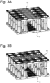
- Figure 2 show a set of identical rainwater crates (one of them in inverted position) stacked by coupling the male and female connectors to each other.
- Another way of stacking a set of identical rainwater crates is by inverting a first rainwater crate 51 and placing the second rainwater crate 52 on the first rainwater crate, such that the base wall of the first rainwater crate is in contact with the base wall of the second rainwater crate and that the supports on the base walls are aligned via protrusions 80.
- the base wall 53 has an average height H3 which increases to an average height H1 when a male support is provided on the base wall.
- Figures 3A and 3B show the identical rainwater crates during installation.
- the rectangular circumferences of the rainwater crates may be aligned to define a cuboid space between the base walls.
- the supports By rotating inverted rainwater crate with respect to the notional axis R, the supports may be aligned to allow stacking of the rainwater crates.
- the male supports of both rainwater crates are aligned (as shown in Figure 3B ).
- the male supports of one rainwater crate are aligned with female supports of the other rainwater crate (as shown in Figure 3A ).
- Figures 4, 5 and 6 show a subterranean rainwater storage device or parts thereof.
- a watertight sheet may be placed onto a flat bottom surface and subsequently a first rainwater crates 51 is laid down on its base wall 53.
- multiple first rainwater crates 51 are laid down adj acent to each other and interlocked to form a matrix of rainwater crates.
- the rainwater crates 51, 52 may be supplied as the stacks (not shown) of nested rainwater crates 51, 52.
- the number of nested rainwater crates 51, 52 per stack then depends on the total weight that can be comfortably carried by one or two human installers, for example up to five stacked rainwater crates 51, 52.
- At least one sedimentation channel 30, as shown in Figure 6 is mounted in the third wall section III.
- the at least one sedimentation channel extends from the supports in the first wall section I to the supports in the first wall section II and a closed floor of the at least one sedimentation channel covers the third wall section III at partially.
- Each sedimentation channel 30, as shown in Figure 5 has an outer shape and outer dimensions such that the sedimentation channel mates with the supports. Because of the complementarity with the supports, the sedimentation channel will have alternative sections with a relatively wide opening and sections with a relatively narrow opening (between the supports) in the length direction L. The sedimentation will happen upon sudden enlarging of channel width due to the slowing down of waterflow.
- the sedimentation channel has an open top and a closed floor.
- a set of rainwater crates is formed by lifting and inverting a second rainwater crate 52, translating it to place it above the first rainwater crates 51 and rotating it to align the male supports of the first rainwater crates 51 with female supports of the second rainwater crate 52, and vice versa.
- the distal ends of the male supports 59 of the inverted rainwater crate 52 each and all stand on the distal ends of the female supports of the first rainwater crate 51
- the distal ends of the female supports 60 of the inverted rainwater crate 52 each and all stand on the distal ends of the male supports of the first rainwater crate 51.
- the rainwater crate 51, the sedimentation channel 30, the side walls 20 and the clips 40 are made of a plastic, in particular a thermoplastic resin, such as polyethylene (PE), polypropylene (PP) or polyvinylchloride (PVC).
- a plastic in particular a thermoplastic resin, such as polyethylene (PE), polypropylene (PP) or polyvinylchloride (PVC).
- PE polyethylene
- PP polypropylene
- PVC polyvinylchloride
- the rainwater crate 51, the sedimentation channel 30, the side walls 20 and the clips 40 are for example made by means of injection moulding.
Landscapes
- Health & Medical Sciences (AREA)
- Life Sciences & Earth Sciences (AREA)
- Engineering & Computer Science (AREA)
- Hydrology & Water Resources (AREA)
- Public Health (AREA)
- Water Supply & Treatment (AREA)
- Sewage (AREA)
Applications Claiming Priority (1)
| Application Number | Priority Date | Filing Date | Title |
|---|---|---|---|
| NL2035466A NL2035466B1 (en) | 2023-07-25 | 2023-07-25 | Subterranean rainwater storage device |
Publications (1)
| Publication Number | Publication Date |
|---|---|
| EP4497883A1 true EP4497883A1 (de) | 2025-01-29 |
Family
ID=88413239
Family Applications (1)
| Application Number | Title | Priority Date | Filing Date |
|---|---|---|---|
| EP24190957.1A Pending EP4497883A1 (de) | 2023-07-25 | 2024-07-25 | Unterirdische regenwasserspeichervorrichtung |
Country Status (2)
| Country | Link |
|---|---|
| EP (1) | EP4497883A1 (de) |
| NL (1) | NL2035466B1 (de) |
Citations (5)
| Publication number | Priority date | Publication date | Assignee | Title |
|---|---|---|---|---|
| WO2011042415A1 (de) | 2009-10-05 | 2011-04-14 | Aco Severin Ahlmann Gmbh & Co. Kg | Rigolenkörper |
| EP2385178A2 (de) * | 2010-05-05 | 2011-11-09 | FRÄNKISCHE ROHRWERKE GEBR. KIRCHNER GmbH & Co KG | Raumsparende Anordnung von Rigolenkomponenten und diese ermöglichende Rigolenkomponente |
| ITBO20110633A1 (it) | 2011-11-07 | 2013-05-08 | Gds S R L | Blocco di infiltrazione per un sistema di infiltrazione per lo smaltimento di acque piovane. |
| EP2862982A1 (de) * | 2013-10-16 | 2015-04-22 | Nidaplast-Honeycombs | Halbes Pufferbehältersmodul für die vorübergehende Speicherung und Lösung von Grundwasser oder Oberflächenwasser ist |
| EP4159944A1 (de) | 2021-10-01 | 2023-04-05 | Dyka B.V. | Unterirdische regenwasserspeichervorrichtung |
-
2023
- 2023-07-25 NL NL2035466A patent/NL2035466B1/en active
-
2024
- 2024-07-25 EP EP24190957.1A patent/EP4497883A1/de active Pending
Patent Citations (5)
| Publication number | Priority date | Publication date | Assignee | Title |
|---|---|---|---|---|
| WO2011042415A1 (de) | 2009-10-05 | 2011-04-14 | Aco Severin Ahlmann Gmbh & Co. Kg | Rigolenkörper |
| EP2385178A2 (de) * | 2010-05-05 | 2011-11-09 | FRÄNKISCHE ROHRWERKE GEBR. KIRCHNER GmbH & Co KG | Raumsparende Anordnung von Rigolenkomponenten und diese ermöglichende Rigolenkomponente |
| ITBO20110633A1 (it) | 2011-11-07 | 2013-05-08 | Gds S R L | Blocco di infiltrazione per un sistema di infiltrazione per lo smaltimento di acque piovane. |
| EP2862982A1 (de) * | 2013-10-16 | 2015-04-22 | Nidaplast-Honeycombs | Halbes Pufferbehältersmodul für die vorübergehende Speicherung und Lösung von Grundwasser oder Oberflächenwasser ist |
| EP4159944A1 (de) | 2021-10-01 | 2023-04-05 | Dyka B.V. | Unterirdische regenwasserspeichervorrichtung |
Also Published As
| Publication number | Publication date |
|---|---|
| NL2035466B1 (en) | 2025-02-10 |
Similar Documents
| Publication | Publication Date | Title |
|---|---|---|
| US6270287B1 (en) | Leaching chamber | |
| AU2010305511B2 (en) | Drainage body | |
| US5498104A (en) | Leaching chamber | |
| AU2020203082B2 (en) | Ground reinforcing structure and related method | |
| EP1280965B1 (de) | Strukturelle modulare verbindbare bodendrainagezelle | |
| US9249570B2 (en) | Connector assembly for modular ground covering panels | |
| EP0206996B1 (de) | Seitenausbau für Dränrohrsystem und Verfahren zum Ausbauen einer fortgehenden Böschung eines Dränrohrsystems | |
| CA1295850C (en) | Modular brickwork form | |
| AU2010247235B2 (en) | A ground-reinforcing grid | |
| AU749743B2 (en) | Revetment block | |
| MX2010008956A (es) | Camara de detención plastica para escorrentia de aguas pluviales y sistema y metodos relacionados. | |
| EP3692209A1 (de) | Kabelkanal | |
| SG181813A1 (en) | Half shell element for the production of a hollow body | |
| CA3168066C (en) | Asymmetric leaching chamber for onsite wastewater management system | |
| EP4497883A1 (de) | Unterirdische regenwasserspeichervorrichtung | |
| AU2020318661A1 (en) | Module for drainage and method of assembly | |
| AU2014326358B2 (en) | Tree root protection panel | |
| EP4159944A1 (de) | Unterirdische regenwasserspeichervorrichtung | |
| WO2013178644A1 (en) | Ducting chamber ring and module, a ducted chamber and a method of assembling a modular chamber system | |
| IL280346B2 (en) | End Caps for Stormwater Chambers and Methods of Making Same | |
| JP3144320U (ja) | 導管システム | |
| JPH10220648A (ja) | 管台用スペーサー | |
| WO2025178686A1 (en) | Drainage body unit | |
| JPH0513596U (ja) | 浄化槽の外槽 | |
| BR112021001366B1 (pt) | Tampas terminais para câmaras de águas pluviais e método de fazer as mesmas |
Legal Events
| Date | Code | Title | Description |
|---|---|---|---|
| PUAI | Public reference made under article 153(3) epc to a published international application that has entered the european phase |
Free format text: ORIGINAL CODE: 0009012 |
|
| STAA | Information on the status of an ep patent application or granted ep patent |
Free format text: STATUS: THE APPLICATION HAS BEEN PUBLISHED |
|
| AK | Designated contracting states |
Kind code of ref document: A1 Designated state(s): AL AT BE BG CH CY CZ DE DK EE ES FI FR GB GR HR HU IE IS IT LI LT LU LV MC ME MK MT NL NO PL PT RO RS SE SI SK SM TR |
|
| STAA | Information on the status of an ep patent application or granted ep patent |
Free format text: STATUS: REQUEST FOR EXAMINATION WAS MADE |
|
| 17P | Request for examination filed |
Effective date: 20250319 |