EP4497842A2 - Systeme und verfahren zur verhinderung der freisetzung und beschädigung von schaufeln in einer gasturbine - Google Patents
Systeme und verfahren zur verhinderung der freisetzung und beschädigung von schaufeln in einer gasturbine Download PDFInfo
- Publication number
- EP4497842A2 EP4497842A2 EP24186727.4A EP24186727A EP4497842A2 EP 4497842 A2 EP4497842 A2 EP 4497842A2 EP 24186727 A EP24186727 A EP 24186727A EP 4497842 A2 EP4497842 A2 EP 4497842A2
- Authority
- EP
- European Patent Office
- Prior art keywords
- airfoil
- anode
- compressor
- sacrificial material
- turbine
- Prior art date
- Legal status (The legal status is an assumption and is not a legal conclusion. Google has not performed a legal analysis and makes no representation as to the accuracy of the status listed.)
- Pending
Links
Images


Classifications
-
- F—MECHANICAL ENGINEERING; LIGHTING; HEATING; WEAPONS; BLASTING
- F01—MACHINES OR ENGINES IN GENERAL; ENGINE PLANTS IN GENERAL; STEAM ENGINES
- F01D—NON-POSITIVE DISPLACEMENT MACHINES OR ENGINES, e.g. STEAM TURBINES
- F01D5/00—Blades; Blade-carrying members; Heating, heat-insulating, cooling or antivibration means on the blades or the members
- F01D5/12—Blades
- F01D5/28—Selecting particular materials; Particular measures relating thereto; Measures against erosion or corrosion
- F01D5/286—Particular treatment of blades, e.g. to increase durability or resistance against corrosion or erosion
-
- C—CHEMISTRY; METALLURGY
- C23—COATING METALLIC MATERIAL; COATING MATERIAL WITH METALLIC MATERIAL; CHEMICAL SURFACE TREATMENT; DIFFUSION TREATMENT OF METALLIC MATERIAL; COATING BY VACUUM EVAPORATION, BY SPUTTERING, BY ION IMPLANTATION OR BY CHEMICAL VAPOUR DEPOSITION, IN GENERAL; INHIBITING CORROSION OF METALLIC MATERIAL OR INCRUSTATION IN GENERAL
- C23F—NON-MECHANICAL REMOVAL OF METALLIC MATERIAL FROM SURFACE; INHIBITING CORROSION OF METALLIC MATERIAL OR INCRUSTATION IN GENERAL; MULTI-STEP PROCESSES FOR SURFACE TREATMENT OF METALLIC MATERIAL INVOLVING AT LEAST ONE PROCESS PROVIDED FOR IN CLASS C23 AND AT LEAST ONE PROCESS COVERED BY SUBCLASS C21D OR C22F OR CLASS C25
- C23F13/00—Inhibiting corrosion of metals by anodic or cathodic protection
- C23F13/02—Inhibiting corrosion of metals by anodic or cathodic protection cathodic; Selection of conditions, parameters or procedures for cathodic protection, e.g. of electrical conditions
- C23F13/06—Constructional parts, or assemblies of cathodic-protection apparatus
- C23F13/08—Electrodes specially adapted for inhibiting corrosion by cathodic protection; Manufacture thereof; Conducting electric current thereto
- C23F13/12—Electrodes characterised by the material
- C23F13/14—Material for sacrificial anodes
-
- C—CHEMISTRY; METALLURGY
- C23—COATING METALLIC MATERIAL; COATING MATERIAL WITH METALLIC MATERIAL; CHEMICAL SURFACE TREATMENT; DIFFUSION TREATMENT OF METALLIC MATERIAL; COATING BY VACUUM EVAPORATION, BY SPUTTERING, BY ION IMPLANTATION OR BY CHEMICAL VAPOUR DEPOSITION, IN GENERAL; INHIBITING CORROSION OF METALLIC MATERIAL OR INCRUSTATION IN GENERAL
- C23F—NON-MECHANICAL REMOVAL OF METALLIC MATERIAL FROM SURFACE; INHIBITING CORROSION OF METALLIC MATERIAL OR INCRUSTATION IN GENERAL; MULTI-STEP PROCESSES FOR SURFACE TREATMENT OF METALLIC MATERIAL INVOLVING AT LEAST ONE PROCESS PROVIDED FOR IN CLASS C23 AND AT LEAST ONE PROCESS COVERED BY SUBCLASS C21D OR C22F OR CLASS C25
- C23F13/00—Inhibiting corrosion of metals by anodic or cathodic protection
- C23F13/02—Inhibiting corrosion of metals by anodic or cathodic protection cathodic; Selection of conditions, parameters or procedures for cathodic protection, e.g. of electrical conditions
- C23F13/06—Constructional parts, or assemblies of cathodic-protection apparatus
- C23F13/08—Electrodes specially adapted for inhibiting corrosion by cathodic protection; Manufacture thereof; Conducting electric current thereto
- C23F13/16—Electrodes characterised by the combination of the structure and the material
-
- F—MECHANICAL ENGINEERING; LIGHTING; HEATING; WEAPONS; BLASTING
- F01—MACHINES OR ENGINES IN GENERAL; ENGINE PLANTS IN GENERAL; STEAM ENGINES
- F01D—NON-POSITIVE DISPLACEMENT MACHINES OR ENGINES, e.g. STEAM TURBINES
- F01D25/00—Component parts, details, or accessories, not provided for in, or of interest apart from, other groups
- F01D25/007—Preventing corrosion
-
- F—MECHANICAL ENGINEERING; LIGHTING; HEATING; WEAPONS; BLASTING
- F01—MACHINES OR ENGINES IN GENERAL; ENGINE PLANTS IN GENERAL; STEAM ENGINES
- F01D—NON-POSITIVE DISPLACEMENT MACHINES OR ENGINES, e.g. STEAM TURBINES
- F01D5/00—Blades; Blade-carrying members; Heating, heat-insulating, cooling or antivibration means on the blades or the members
- F01D5/12—Blades
- F01D5/28—Selecting particular materials; Particular measures relating thereto; Measures against erosion or corrosion
- F01D5/288—Protective coatings for blades
-
- F—MECHANICAL ENGINEERING; LIGHTING; HEATING; WEAPONS; BLASTING
- F02—COMBUSTION ENGINES; HOT-GAS OR COMBUSTION-PRODUCT ENGINE PLANTS
- F02C—GAS-TURBINE PLANTS; AIR INTAKES FOR JET-PROPULSION PLANTS; CONTROLLING FUEL SUPPLY IN AIR-BREATHING JET-PROPULSION PLANTS
- F02C7/00—Features, components parts, details or accessories, not provided for in, or of interest apart form groups F02C1/00 - F02C6/00; Air intakes for jet-propulsion plants
- F02C7/30—Preventing corrosion or unwanted deposits in gas-swept spaces
-
- F—MECHANICAL ENGINEERING; LIGHTING; HEATING; WEAPONS; BLASTING
- F05—INDEXING SCHEMES RELATING TO ENGINES OR PUMPS IN VARIOUS SUBCLASSES OF CLASSES F01-F04
- F05D—INDEXING SCHEME FOR ASPECTS RELATING TO NON-POSITIVE-DISPLACEMENT MACHINES OR ENGINES, GAS-TURBINES OR JET-PROPULSION PLANTS
- F05D2220/00—Application
- F05D2220/30—Application in turbines
- F05D2220/32—Application in turbines in gas turbines
-
- F—MECHANICAL ENGINEERING; LIGHTING; HEATING; WEAPONS; BLASTING
- F05—INDEXING SCHEMES RELATING TO ENGINES OR PUMPS IN VARIOUS SUBCLASSES OF CLASSES F01-F04
- F05D—INDEXING SCHEME FOR ASPECTS RELATING TO NON-POSITIVE-DISPLACEMENT MACHINES OR ENGINES, GAS-TURBINES OR JET-PROPULSION PLANTS
- F05D2230/00—Manufacture
- F05D2230/90—Coating; Surface treatment
-
- F—MECHANICAL ENGINEERING; LIGHTING; HEATING; WEAPONS; BLASTING
- F05—INDEXING SCHEMES RELATING TO ENGINES OR PUMPS IN VARIOUS SUBCLASSES OF CLASSES F01-F04
- F05D—INDEXING SCHEME FOR ASPECTS RELATING TO NON-POSITIVE-DISPLACEMENT MACHINES OR ENGINES, GAS-TURBINES OR JET-PROPULSION PLANTS
- F05D2260/00—Function
- F05D2260/95—Preventing corrosion
-
- F—MECHANICAL ENGINEERING; LIGHTING; HEATING; WEAPONS; BLASTING
- F05—INDEXING SCHEMES RELATING TO ENGINES OR PUMPS IN VARIOUS SUBCLASSES OF CLASSES F01-F04
- F05D—INDEXING SCHEME FOR ASPECTS RELATING TO NON-POSITIVE-DISPLACEMENT MACHINES OR ENGINES, GAS-TURBINES OR JET-PROPULSION PLANTS
- F05D2300/00—Materials; Properties thereof
- F05D2300/60—Properties or characteristics given to material by treatment or manufacturing
- F05D2300/611—Coating
Definitions
- the present disclosure relates generally to gas turbine engines and more particularly relates to systems and methods for preventing and limiting the effects of liberation and damage to airfoils in a gas turbine.
- Gas turbines are conventionally made of two distinct sections: a compressor section and a turbine section.
- the compressor section takes in air, or another suitable gas, and compresses it volumetrically.
- the turbine section mixes the flow of compressed air that comes from the compressor section of the gas turbine with a flow of fuel to generate hot combustion gases.
- a turbine in the turbine section receives the flow of hot combustion gases from the combustor and extracts energy from the gases for powering the compressor and for outputting power to an external load such as an electrical generator and the like.
- the compressor section there are a multitude of airfoils connected around a central shaft which rotates, enabling the airfoils to compress the ambient air as it is pulled into the compressor. For example, there may be around 19 stages of compressor airfoil sections within the compressor section.
- This galvanic protection layer helps to protect the substrate from corrosive environments, and helps to ensure that there is an electrically conductive path between the galvanic protection layer and the steel substrate.
- Such galvanic protection layers may be made of sacrificial materials, like aluminum or other electrically conductive materials.
- this galvanic protection layer is applied as a coating to the entire surface of each individual airfoil.
- the galvanic protection layer coating may degrade the surface finish over time and reduce the overall efficiency of the compressor because the surface finish itself may form pits or gaps in the coating which roughen the surface of the airfoil.
- Mitigating degradation due to the galvanic protection coating may be achieved through the use of replaceable anodes made of the sacrificial material. These anodes may take a variety of different shapes and can be located at specific locations on turbine components to improve the corrosion resistance without reducing the efficiency of the compressor or degrading the finish of the substrate. Furthermore, the individual airfoils, and each stage of airfoils as a whole, can be modified in their shape, orientation, and design to better direct condensed water to the anodes and create a more efficient corrosion-prevention system.
- This galvanic protection layer therefore increases the resistance of the turbine components to corrosion and other damaging effects caused by corrosion, such as pitting, and the anode prevents degradation of the surface finish caused by the galvanic protection layer, enabling the airfoils and other turbine components to function safely for longer time periods between maintenance or replacements.
- the turbine protection system includes at least one airfoil engaged with a compressor.
- an "airfoil” is an aerodynamic body configured to generate lift as air passes over the surface of the airfoil.
- the compressor of gas turbines typically include dozens of compressor blades in the form of both “rotor blades” and “stator vanes,” and these compressor blades are typically separated into the “airfoil” portion that is responsible for compressing air, and a “base” portion responsible for coupling the airfoil to the compressor shaft.
- airfoil is used herein to refer to the entire compressor blade of either the rotor or stator.
- rotor blades and stator vanes may vary in shape depending on the desired airflow characteristics through a compressor, the protection system described herein may be implemented on rotors or stators of any shape.
- the at least one airfoil includes a blade, a platform, a dovetail, and a base.
- the "blade” of the airfoil is the characteristic wing-shaped portion responsible for compressing air when the airfoil is in motion as part of a compressor.
- the "base” or root of the airfoil typically characterized by a curved joint, represents the portion of the airfoil where the blade joins the platform.
- the "platform” of the airfoil generally defines the radially inner boundary of the air flow path across the blade surface. When a number of airfoils are positioned together on the compressor disk, the platforms of each airfoil approximate a smooth cylindrical surface.
- the "dovetail" of the airfoil is configured to join the airfoil to the compressor disk; the eponymous dovetail-shape is configured to secure the airfoil in the compressor disk such that, when the compressor spins, the dovetail experiences a higher pressure and more secure fitting within the compressor disk.
- the turbine protection system includes one or more anodes attached to the airfoil.
- the anode may be attached to any suitable portion of the airfoil, including the platform, base, dovetail, or blade, depending on the corrosion-prevention needs of the particular turbine and/or airfoil.
- the one or more anodes includes a sacrificial material configured to provide galvanic protection against corrosion. The sacrificial material may be positioned between the anode and the airfoil.
- the anode is formed from aluminum, zinc, magnesium, lithium, or a combination thereof.
- the sacrificial material is formed from aluminum, zinc, magnesium, or a combination thereof.
- a sacrificial material such as aluminum, zinc, or magnesium encourages corrosion of the sacrificial material instead of the airfoil itself.
- anodic material it has been unexpectedly discovered that the sacrificial material may be significantly reduced in size without compromising the corrosion inhibition properties.
- conventional corrosion inhibition techniques involve coating the entire airfoil in a sacrificial material.
- corrosion may be further encouraged to selectively affect the sacrificial material rather than the airfoil without impacting the aerodynamic surface of the airfoil.
- the anode In embodiments in which the anode is incorporated within the surface of the airfoil, i.e., in substitution of the airfoil material otherwise present, the anode has the same mass as the portion of the airfoil, platform, dovetail, or other compressor component that the anode is being inlaid in substitution for.
- the turbine protection system further includes a conductive material coated onto the sacrificial material between the sacrificial material and the anode.
- the conductive material includes bronze, iron, brass, or an alloy thereof. Without intending to be bound by any particular theory, it is believed that the inclusion of a conductive material on the sacrificial material enhances the ability for the anode to promote corrosion of the sacrificial material.
- the conductive material is attached through the use of an adhesive, a mechanical securing means such as a screw or bolt, or manufactured as part of the anode with the sacrificial material.
- This conductive material may be of the same or different thickness and/or shape as the sacrificial material. Without intending to be bound by any particular theory, it is believed that having a differently shaped or different thickness conductive material as compared to the sacrificial material may allow for increased effectiveness in directing the water to the sacrificial material.
- the conductive material is attached above the sacrificial layer and is shaped to have channels, grooves, gaps, or holes. In other embodiments, the conductive material is attached below the sacrificial material.
- the duration of corrosion-prevent effects may be enhanced because, as the sacrificial layer begins to corrode, the conductive material may supplement the anodic attraction of corrosive elements in the condensed water .
- the anode is detachably attachable to the airfoil. It has been unexpectedly discovered that forming the turbine protection system from one or more anodes capable of being detachably attached enables the ability to add one or more anodes in any particular position on the airfoil in order to reduce or substantially eliminate corrosion of the airfoil. Furthermore, the anode may be removed at any convenient time, such as during a period of planned downtime, without requiring the sacrificial material to be fully corroded, ensuring the anodes have the optimal degree of corrosion prevention at any given time.
- the anode is attached using an adhesive.
- the adhesive includes epoxy, polyurethane, cyanoacrylate, anaerobic adhesives, silicone, or acrylic adhesives.
- the portion of the anode is coated with epoxy and is inlaid in the platform such that the top surface of the anode is sitting flush with the surface of the platform.
- the adhesive may be first applied to the surface of the compressor component.
- a portion of the anode is designed to have grooves or channels configured to guide the application of the adhesive.
- the adhesive is an industrial tape.
- the adhesive may include polyimide tape or self-fusing silicone tape.
- the anode is attached to the airfoil or other compressor component through notched protrusion which connects into a groove or channel.
- the anode may comprise a small protrusion having a rectangular shape and the airfoil may comprise an opening in a cavity having a complementary shape to the protrusion on the anode such that the protrusion may be inserted into the opening and moved, rotated, or translated into a secondary position in the cavity such that the connection is secure.
- the protrusion is rectangular, square, angled, or trapezoidal.
- each anode has a unique protrusion configured to be inserted into exactly one corresponding opening, such as when the anode is shaped and/or sized to produce anti-corrosive effects in a particular location on the airfoil.
- the anode is attached to the airfoil or other compressor component through a threaded component.
- the anode includes male or a female threaded portion, parallel threads, tapered threads, or multi-start threads, and the airfoil or other compressor component includes a complementary portion of the threaded system.
- the system may provide simpler method of attaching and detaching the anodes.
- different anodes may have different thread types or thread sizes, wherein the thread is specific to the anode's attachment at a specific location on the airfoil or other compressor component.
- the threaded component is a vibration resistant screw.
- the threaded component is combined with a threadlocker, such as an adhesive that is applied to the threads, of either the compressor component or the anode.
- a threadlocker such as an adhesive that is applied to the threads, of either the compressor component or the anode.
- some anodes have a protrusion/opening means of securing to the airfoil, while some anodes are attached using a threaded means.
- the anode is attached to the airfoil or other compressor component using a magnetic connection.
- the magnetic connection includes at least two permanent magnets, which may include neodymium iron boron, samarium cobalt, alnico, or ceramic/ferrite magnets.
- the magnetic connection includes at least one temporary magnet.
- a temporary magnet such as a soft iron device, may be attached to the anode and may engage with another magnet, either temporary, permanent, or electromagnetic, attached to the airfoil or other compressor component.
- the magnetic connection includes electromagnets.
- a solenoid contained within the airfoil or other compressor component may be used to attach an anode that includes a magnetic component.
- the anode is machined to be a part of the airfoil, platform, dovetail, or other compressor component.
- the anode is machined to be a part of the airfoil, platform, dovetail, or other compressor component.
- the anode is comprised of multiple layers of different material.
- the anode may include a base layer made of a non-sacrificial material and a top layer including the sacrificial material.
- the anode may be more easily attached to the airfoil or other compressor component.
- the base layer may be machined to have a notch that engaged within the airfoil or platform enabling the anode to be easily attachable and detachable.
- the base layer may include an adhesive component, a female thread port, a male thread port, a carbon plate, or another suitable attachment method.
- an anode having at least two layers of different sacrificial material may be able to corrode at a reduced rate.
- the top layer may include aluminum and a bottom layer may include magnesium.
- the layers may be of the same or different thicknesses and/or shapes.
- a layer of the conductive material may be added to the anode to increase the effectiveness of the anode.
- a conductive layer may be positioned between the top layer and the bottom layer.
- the conductive layer may be positioned on top of both the top layer and the bottom layer.
- the conductive layer may be positioned only on top of the top layer. This conductive layer may be of the same or different thickness and/or shape as the sacrificial material layer.
- the airfoils, casing, platform, turbine, or other parts of the compressor section of the gas turbine are shaped to direct water towards the anodes, or may include shaped features configured to direct water towards the anodes.
- the turbine can more effectively move water away from the airfoils and non-anode components and further reduce the chance of those components corroding.
- the components, such as the airfoil may have channels carved into them that do not affect the overall performance or effectiveness of the compressor, but nonetheless facilitate the redirection of condensed water to one or more anodes.
- these channels may be added after the airfoil has been manufactured through a secondary process, or the channel may be machined into the airfoil during the manufacturing process.
- these channels or other forms of directing water from the components can be specifically designed for different anode placements. For example, different channels may be present that each redirect water to a different anode.
- different airfoils within an airfoil stage of the compressor have different channels. By directing the water in different directions for different airfoils within an airfoil stage, the channels can better use the force of gravity to direct the water to the anodes. As described above, water may condense and enable corrosion when the turbine is idle or disengaged, i.e., when the airfoils are not rotating.
- an airfoil that is angled horizontally from the central shaft when the turbine is disengaged may use channels that direct the water diagonally toward an anode of the platform, whereas an airfoil that is angled downward from the central shaft may use channels that direct the water downward toward an anode on the tip of the airfoil.
- the anode may be sized and shaped to fit into specific portions of the airfoil, dovetail, platform, or other compressor parts.
- the anode may have a top surface which is circular, rectangular, trapezoidal, square, trigonal, rhombus, or a comparable shape.
- the anode can be more effectively attached to different compressor components because each part has different shapes, angles, locations, and sizes.
- the anode has multiple levels of elevation to match the curvature of the platform.
- the anode has grooves, channels, or other surface design. By including texture to the surface of the anode, the anode may have increased effectiveness in some embodiments as the sacrificial material will corrode more readily and in a more precise pattern.
- the anode is attached to the tip of the airfoil.
- the airfoil can utilize the effects of gravity to help direct water to the anode.
- some airfoils are facing downwards from the central shaft, it is therefore preferable in some embodiments to have the anode on the tip of the airfoil.
- anodes attached to different locations of the airfoil, platform, dovetail, or other compressor component.
- the anodes can more effectively direct the water on the airfoil or components to the sacrificial material.
- an airfoil when the gas turbine is idling or shutdown, may point in different directions away from the central shaft at different times. It therefore may be preferable to have anodes at different locations along the airfoil or other compressor component so that the water may be directed to a more preferable anode based on proximity and direction.
- the anode is attached to the inside of the casing of the compressor.
- Some compressors include airfoils that are in constant contact with the casing, or the separation between the airfoils and the casing is small enough for the water to contact the anodes from the tip of the blade. Without intending to be bound by any particular theory, it is believed that attaching anodes inside the casing of the compressor may allow for more efficient corrosion prevention in instances where the condensed water collects at the tip of the airfoil or is transferred from the tip of the airfoil to the inside casing of the compressor.
- FIG. 1 shows a schematic diagram of a gas turbine engine 100 as may be used herein.
- the gas turbine engine 100 may include a compressor 102.
- the compressor 102 compresses an incoming flow of air 104.
- the compressor 102 delivers the compressed flow of air 104 to a number of combustor cans 106.
- the combustor cans 106 mix the compressed flow of air 104 with a pressurized flow of fuel 108 and ignite the mixture to create a flow of hot combustion gases 110.
- the gas turbine engine 100 may include any number of combustor cans 106 positioned in a circumferential array and the like.
- the combustor 106 may be an annular combustor.
- the flow of combustion gases 110 is in turn delivered to a turbine 112.
- the flow of combustion gases 110 drives the turbine 112 to produce mechanical work.
- the mechanical work produced in the turbine 112 drives the compressor 102 via a rotor shaft 114 and an external load 116 such as an electrical generator and the like.
- the gas turbine engine 100 may use natural gas, various types of syngas, liquid fuels, and/or other types of fuels and blends thereof.
- the gas turbine engine 100 may be any one of a number of different gas turbine engines offered by General Electric Company of Schenectady, New York, including, but not limited to, those such as a 7-series or a 9-series heavy duty gas turbine engine and the like.
- the gas turbine engine 100 may be part of a simple cycle or a combined cycle power generation system or other types of generation systems.
- the gas turbine engine 100 may have different configurations and may use other types of components. Other types of gas turbine engines also may be used herein. Multiple gas turbine engines, other types of turbines, and other types of power generation equipment also may be used herein together.
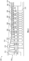
- FIG. 2 shows an example of the compressor 200.
- the compressor 200 may include a number of compressor stages, also referred to as rotor/stator stages, with an axial compressor flow path 202 therethrough.
- the exact number of rotor and stator stages may be a matter of engineering design choice and may be more or fewer than the illustrated stages. It is to be understood that any number of rotor and stator stages may be provided herein.
- Each stage of the compressor 200 may include a number of circumferentially spaced rotor blades 204 mounted on a rotor wheel 206 and a number of circumferentially spaced stator vanes 208 attached to a static compressor case 210.
- Each of the rotor wheels 206 may be attached to an aft drive shaft 212, which may be connected to the turbine section of the engine.
- the rotor blades and stator vanes may lie in the flow path 202 of the compressor 200.
- the direction of airflow through the compressor flow path 202 flows generally from left to right in FIG. 2 .
- Other components and other configurations may be used herein.
- the compressor rotor blades 204 impart kinetic energy to the airflow and therefore bring about a desired pressure rise.
- Directly following the rotor blades 204 may be a stage of the compressor stator vanes 208. However, in some designs the stator vanes may precede the rotor blades. Both the rotor blades and stator vanes turn the airflow, slow the airflow velocity (in the respective airfoil frame of reference), and yield a rise in the static pressure of the airflow.
- multiple rows of rotor/stator stages are arranged in axial flow compressors to achieve a desired discharge to inlet pressure ratio.
- Each rotor blade and stator vane includes an airfoil as described herein, and these airfoils can be secured to rotor wheels or a stator case by an appropriate attachment configuration, often known as a "root,” “base” or “dovetail”.
- the compressor 200 also may include inlet guide vanes (IGV's) 214, variable stator vanes (VSV's) 216, and exit or exhaust guide vanes (EGV's) 218. All of these blades and vanes have airfoils that act on the medium (e.g., air) passing through the compressor flow path 202.
- the medium e.g., air
- all of the airfoils on the blades and vanes described in Fig. 2 may be susceptible to pitting as a result of moisture and/or corrosion.
- Other components and other configurations may be used herein.
- Fig. 3 shows an exemplary rotor blade or airfoil 300 that may be incorporated into the compressor of Fig. 2 in one or more of the rotor blade(s), stator vane(s), variable stator vane(s), and/or exit or exhaust guide vane(s).
- the airfoil 300 extends from an axially forward leading edge 302 to an axially aft trailing edge 304 and from a radially inward base or root 306 to a radially outer tip 308.
- the airfoil 300 includes a platform 310 defining a radially inner boundary of a gas path.
- the airfoil 300 also includes a dovetail 312.
- the airfoil 300 also illustrates an anode 314 positioned on the platform 310, as well as an anode 314 on the dovetail 312.
Landscapes
- Engineering & Computer Science (AREA)
- Mechanical Engineering (AREA)
- Chemical & Material Sciences (AREA)
- General Engineering & Computer Science (AREA)
- Materials Engineering (AREA)
- Combustion & Propulsion (AREA)
- Metallurgy (AREA)
- Organic Chemistry (AREA)
- Structures Of Non-Positive Displacement Pumps (AREA)
- Prevention Of Electric Corrosion (AREA)
- Turbine Rotor Nozzle Sealing (AREA)
Applications Claiming Priority (1)
| Application Number | Priority Date | Filing Date | Title |
|---|---|---|---|
| US18/358,413 US12060802B1 (en) | 2023-07-25 | 2023-07-25 | Systems and methods for preventing liberation and damage to airfoils in a gas turbine |
Publications (2)
| Publication Number | Publication Date |
|---|---|
| EP4497842A2 true EP4497842A2 (de) | 2025-01-29 |
| EP4497842A3 EP4497842A3 (de) | 2025-07-16 |
Family
ID=91853242
Family Applications (1)
| Application Number | Title | Priority Date | Filing Date |
|---|---|---|---|
| EP24186727.4A Pending EP4497842A3 (de) | 2023-07-25 | 2024-07-05 | Systeme und verfahren zur verhinderung der freisetzung und beschädigung von schaufeln in einer gasturbine |
Country Status (4)
| Country | Link |
|---|---|
| US (2) | US12060802B1 (de) |
| EP (1) | EP4497842A3 (de) |
| JP (1) | JP2025022757A (de) |
| KR (1) | KR20250015984A (de) |
Family Cites Families (19)
| Publication number | Priority date | Publication date | Assignee | Title |
|---|---|---|---|---|
| US3081252A (en) * | 1959-09-30 | 1963-03-12 | Chemionics Engineering Lab Inc | Pipe plug anode |
| US3441491A (en) * | 1966-03-03 | 1969-04-29 | Dow Chemical Co | Packaged galvanic anodes |
| JP2000204902A (ja) * | 1999-01-08 | 2000-07-25 | Hitachi Ltd | タ―ビン、タ―ビンロ―タ、及びタ―ビン動翼 |
| JP2001289144A (ja) * | 2000-04-11 | 2001-10-19 | Hitachi Ltd | 水車羽根車 |
| EP1722011A1 (de) * | 2005-05-11 | 2006-11-15 | Siemens Aktiengesellschaft | Turbinenkomponente, elektrisches System mit der Turbinenkomponente, Brenner, Turbine und Verfahren zur Verminderung von Korrosion bei einer Turbinenkomponente |
| US20090176110A1 (en) * | 2008-01-08 | 2009-07-09 | General Electric Company | Erosion and corrosion-resistant coating system and process therefor |
| US8118983B1 (en) * | 2010-01-15 | 2012-02-21 | Brunswick Corporation | System for inhibiting corrosion of submerged components in a marine propulsion system |
| CN103534573A (zh) * | 2010-12-21 | 2014-01-22 | 涂层国外知识产权有限公司 | 耐腐蚀性的评估方法 |
| US20120189425A1 (en) * | 2011-01-24 | 2012-07-26 | General Electric Company | System and method for reducing corrosion in a compressor |
| GB201210361D0 (en) * | 2012-06-12 | 2012-07-25 | Fugro Subsea Services Ltd | Apparatus and method |
| ES2745534T3 (es) * | 2012-07-30 | 2020-03-02 | Construction Research & Technology Gmbh | Anodo galvánico y procedimiento de protección contra la corrosión |
| US9322283B2 (en) * | 2012-09-28 | 2016-04-26 | United Technologies Corporation | Airfoil with galvanic corrosion preventive shim |
| US9159980B2 (en) * | 2012-12-27 | 2015-10-13 | General Electric Company | Electrochemical cell |
| US10301950B2 (en) * | 2013-03-15 | 2019-05-28 | United Technologies Corporation | Enhanced protection for aluminum fan blade via sacrificial layer |
| WO2015047756A1 (en) | 2013-09-27 | 2015-04-02 | United Technologies Corporation | Fan blade assembly |
| US10640877B2 (en) * | 2015-11-03 | 2020-05-05 | Vector Remediation Ltd. | Cathodic corrosion protection |
| US10794193B2 (en) * | 2016-08-23 | 2020-10-06 | United Technologies Corporation | Air foil with galvanic protection |
| KR102575226B1 (ko) * | 2016-12-08 | 2023-09-05 | 한화파워시스템 주식회사 | 희생양극을 구비한 임펠러 |
| US20180202299A1 (en) | 2017-01-18 | 2018-07-19 | United Technologies Corporation | Fan blade with anode and method for galvanic corrosion mitigation |
-
2023
- 2023-07-25 US US18/358,413 patent/US12060802B1/en active Active
-
2024
- 2024-05-28 US US18/675,913 patent/US20250035011A1/en active Pending
- 2024-06-24 JP JP2024101004A patent/JP2025022757A/ja active Pending
- 2024-07-05 EP EP24186727.4A patent/EP4497842A3/de active Pending
- 2024-07-19 KR KR1020240095587A patent/KR20250015984A/ko active Pending
Also Published As
| Publication number | Publication date |
|---|---|
| US12060802B1 (en) | 2024-08-13 |
| US20250035011A1 (en) | 2025-01-30 |
| JP2025022757A (ja) | 2025-02-14 |
| EP4497842A3 (de) | 2025-07-16 |
| KR20250015984A (ko) | 2025-02-03 |
Similar Documents
| Publication | Publication Date | Title |
|---|---|---|
| EP2369155B1 (de) | Nasenkonus einer Gasturbine | |
| US8215914B2 (en) | Compliant seal for rotor slot | |
| JP5639852B2 (ja) | 熱シールド装置及び、その交換方法 | |
| EP3121378B1 (de) | Schaufel für einen gasturbinenmotor | |
| US9009965B2 (en) | Method to center locate cutter teeth on shrouded turbine blades | |
| US20170009584A1 (en) | Systems and Methods for Turbine Blade Repair | |
| EP2230387A2 (de) | Gehäuseanordnung eines Gasturbinen-Triebwerks zur Reduzierung des Rotor-Laufspalts | |
| US8915713B2 (en) | Offset counterbore for airfoil cooling hole | |
| EP2204534B1 (de) | Synchronisierung von Gasturbinenschaufeln | |
| US20070169462A1 (en) | Gas turbine, especially an aircraft engine | |
| US7210909B2 (en) | Connection between bladed discs on the rotor line of a compressor | |
| EP2204533A2 (de) | Verfahren, Systeme und/oder Vorrichtungen in Bezug auf Drallvorrichtungen für Turbinenantriebe | |
| JP2010019261A (ja) | タービンダブテール用のスプリングシール | |
| CN110836130B (zh) | 涡轮机、燃气涡轮机及涡轮叶片分离方法 | |
| EP3144480A1 (de) | Ausnehmung im laufschaufelfuss zur spannungsverminderung | |
| US8210823B2 (en) | Method and apparatus for creating seal slots for turbine components | |
| US12060802B1 (en) | Systems and methods for preventing liberation and damage to airfoils in a gas turbine | |
| US10570754B2 (en) | Steam turbine rotor blade, method for manufacturing steam turbine rotor blade, and steam turbine | |
| US20170159480A1 (en) | Seal assembly for a turbomachine | |
| US20150377058A1 (en) | Axial Turbomachine Compressor Inner Shell | |
| WO2014068355A1 (en) | Gas turbine engine exhaust system and corresponding method for accessing turbine buckets | |
| US9470098B2 (en) | Axial compressor and method for controlling stage-to-stage leakage therein | |
| US20150118031A1 (en) | System and a method of installing a tip shroud ring in turbine disks | |
| RU2614892C2 (ru) | Внутренняя платформа сопловой лопатки турбины и сопловая лопатка турбины (варианты) | |
| US10822976B2 (en) | Nozzle insert rib cap |
Legal Events
| Date | Code | Title | Description |
|---|---|---|---|
| PUAI | Public reference made under article 153(3) epc to a published international application that has entered the european phase |
Free format text: ORIGINAL CODE: 0009012 |
|
| STAA | Information on the status of an ep patent application or granted ep patent |
Free format text: STATUS: THE APPLICATION HAS BEEN PUBLISHED |
|
| AK | Designated contracting states |
Kind code of ref document: A2 Designated state(s): AL AT BE BG CH CY CZ DE DK EE ES FI FR GB GR HR HU IE IS IT LI LT LU LV MC ME MK MT NL NO PL PT RO RS SE SI SK SM TR |
|
| PUAL | Search report despatched |
Free format text: ORIGINAL CODE: 0009013 |
|
| AK | Designated contracting states |
Kind code of ref document: A3 Designated state(s): AL AT BE BG CH CY CZ DE DK EE ES FI FR GB GR HR HU IE IS IT LI LT LU LV MC ME MK MT NL NO PL PT RO RS SE SI SK SM TR |
|
| RIC1 | Information provided on ipc code assigned before grant |
Ipc: C23F 13/14 20060101AFI20250606BHEP Ipc: F01D 5/28 20060101ALI20250606BHEP Ipc: C23F 13/16 20060101ALI20250606BHEP Ipc: F01D 25/00 20060101ALI20250606BHEP |
|
| RAP3 | Party data changed (applicant data changed or rights of an application transferred) |
Owner name: GE VERNOVA TECHNOLOGY GMBH |
|
| STAA | Information on the status of an ep patent application or granted ep patent |
Free format text: STATUS: REQUEST FOR EXAMINATION WAS MADE |
|
| 17P | Request for examination filed |
Effective date: 20251006 |