EP4497714A1 - Wire transfer device - Google Patents
Wire transfer device Download PDFInfo
- Publication number
- EP4497714A1 EP4497714A1 EP24189963.2A EP24189963A EP4497714A1 EP 4497714 A1 EP4497714 A1 EP 4497714A1 EP 24189963 A EP24189963 A EP 24189963A EP 4497714 A1 EP4497714 A1 EP 4497714A1
- Authority
- EP
- European Patent Office
- Prior art keywords
- wire
- guide roller
- transfer device
- foil
- exemplary embodiment
- Prior art date
- Legal status (The legal status is an assumption and is not a legal conclusion. Google has not performed a legal analysis and makes no representation as to the accuracy of the status listed.)
- Pending
Links
Images




Classifications
-
- B—PERFORMING OPERATIONS; TRANSPORTING
- B65—CONVEYING; PACKING; STORING; HANDLING THIN OR FILAMENTARY MATERIAL
- B65H—HANDLING THIN OR FILAMENTARY MATERIAL, e.g. SHEETS, WEBS, CABLES
- B65H59/00—Adjusting or controlling tension in filamentary material, e.g. for preventing snarling; Applications of tension indicators
- B65H59/10—Adjusting or controlling tension in filamentary material, e.g. for preventing snarling; Applications of tension indicators by devices acting on running material and not associated with supply or take-up devices
- B65H59/20—Co-operating surfaces mounted for relative movement
- B65H59/26—Co-operating surfaces mounted for relative movement and arranged to deflect material from straight path
-
- B—PERFORMING OPERATIONS; TRANSPORTING
- B65—CONVEYING; PACKING; STORING; HANDLING THIN OR FILAMENTARY MATERIAL
- B65H—HANDLING THIN OR FILAMENTARY MATERIAL, e.g. SHEETS, WEBS, CABLES
- B65H49/00—Unwinding or paying-out filamentary material; Supporting, storing or transporting packages from which filamentary material is to be withdrawn or paid-out
- B65H49/18—Methods or apparatus in which packages rotate
- B65H49/20—Package-supporting devices
- B65H49/30—Swifts or skein holders
-
- B—PERFORMING OPERATIONS; TRANSPORTING
- B65—CONVEYING; PACKING; STORING; HANDLING THIN OR FILAMENTARY MATERIAL
- B65H—HANDLING THIN OR FILAMENTARY MATERIAL, e.g. SHEETS, WEBS, CABLES
- B65H16/00—Unwinding, paying-out webs
-
- B—PERFORMING OPERATIONS; TRANSPORTING
- B65—CONVEYING; PACKING; STORING; HANDLING THIN OR FILAMENTARY MATERIAL
- B65H—HANDLING THIN OR FILAMENTARY MATERIAL, e.g. SHEETS, WEBS, CABLES
- B65H49/00—Unwinding or paying-out filamentary material; Supporting, storing or transporting packages from which filamentary material is to be withdrawn or paid-out
- B65H49/18—Methods or apparatus in which packages rotate
- B65H49/20—Package-supporting devices
- B65H49/32—Stands or frameworks
-
- B—PERFORMING OPERATIONS; TRANSPORTING
- B65—CONVEYING; PACKING; STORING; HANDLING THIN OR FILAMENTARY MATERIAL
- B65H—HANDLING THIN OR FILAMENTARY MATERIAL, e.g. SHEETS, WEBS, CABLES
- B65H49/00—Unwinding or paying-out filamentary material; Supporting, storing or transporting packages from which filamentary material is to be withdrawn or paid-out
- B65H49/18—Methods or apparatus in which packages rotate
- B65H49/34—Arrangements for effecting positive rotation of packages
-
- B—PERFORMING OPERATIONS; TRANSPORTING
- B65—CONVEYING; PACKING; STORING; HANDLING THIN OR FILAMENTARY MATERIAL
- B65H—HANDLING THIN OR FILAMENTARY MATERIAL, e.g. SHEETS, WEBS, CABLES
- B65H54/00—Winding, coiling, or depositing filamentary material
- B65H54/02—Winding and traversing material on to reels, bobbins, tubes, or like package cores or formers
- B65H54/40—Arrangements for rotating packages
- B65H54/44—Arrangements for rotating packages in which the package, core, or former is engaged with, or secured to, a driven member rotatable about the axis of the package
-
- B—PERFORMING OPERATIONS; TRANSPORTING
- B65—CONVEYING; PACKING; STORING; HANDLING THIN OR FILAMENTARY MATERIAL
- B65H—HANDLING THIN OR FILAMENTARY MATERIAL, e.g. SHEETS, WEBS, CABLES
- B65H57/00—Guides for filamentary materials; Supports therefor
- B65H57/14—Pulleys, rollers, or rotary bars
-
- B—PERFORMING OPERATIONS; TRANSPORTING
- B65—CONVEYING; PACKING; STORING; HANDLING THIN OR FILAMENTARY MATERIAL
- B65H—HANDLING THIN OR FILAMENTARY MATERIAL, e.g. SHEETS, WEBS, CABLES
- B65H57/00—Guides for filamentary materials; Supports therefor
- B65H57/24—Guides for filamentary materials; Supports therefor with wear-resistant surfaces
-
- B—PERFORMING OPERATIONS; TRANSPORTING
- B65—CONVEYING; PACKING; STORING; HANDLING THIN OR FILAMENTARY MATERIAL
- B65H—HANDLING THIN OR FILAMENTARY MATERIAL, e.g. SHEETS, WEBS, CABLES
- B65H59/00—Adjusting or controlling tension in filamentary material, e.g. for preventing snarling; Applications of tension indicators
- B65H59/10—Adjusting or controlling tension in filamentary material, e.g. for preventing snarling; Applications of tension indicators by devices acting on running material and not associated with supply or take-up devices
-
- B—PERFORMING OPERATIONS; TRANSPORTING
- B65—CONVEYING; PACKING; STORING; HANDLING THIN OR FILAMENTARY MATERIAL
- B65H—HANDLING THIN OR FILAMENTARY MATERIAL, e.g. SHEETS, WEBS, CABLES
- B65H59/00—Adjusting or controlling tension in filamentary material, e.g. for preventing snarling; Applications of tension indicators
- B65H59/10—Adjusting or controlling tension in filamentary material, e.g. for preventing snarling; Applications of tension indicators by devices acting on running material and not associated with supply or take-up devices
- B65H59/36—Floating elements compensating for irregularities in supply or take-up of material
-
- B—PERFORMING OPERATIONS; TRANSPORTING
- B65—CONVEYING; PACKING; STORING; HANDLING THIN OR FILAMENTARY MATERIAL
- B65H—HANDLING THIN OR FILAMENTARY MATERIAL, e.g. SHEETS, WEBS, CABLES
- B65H61/00—Applications of devices for metering predetermined lengths of running material
-
- B—PERFORMING OPERATIONS; TRANSPORTING
- B65—CONVEYING; PACKING; STORING; HANDLING THIN OR FILAMENTARY MATERIAL
- B65H—HANDLING THIN OR FILAMENTARY MATERIAL, e.g. SHEETS, WEBS, CABLES
- B65H75/00—Storing webs, tapes, or filamentary material, e.g. on reels
- B65H75/02—Cores, formers, supports, or holders for coiled, wound, or folded material, e.g. reels, spindles, bobbins, cop tubes, cans, mandrels or chucks
- B65H75/34—Cores, formers, supports, or holders for coiled, wound, or folded material, e.g. reels, spindles, bobbins, cop tubes, cans, mandrels or chucks specially adapted or mounted for storing and repeatedly paying-out and re-storing lengths of material provided for particular purposes, e.g. anchored hoses, power cables
- B65H75/38—Cores, formers, supports, or holders for coiled, wound, or folded material, e.g. reels, spindles, bobbins, cop tubes, cans, mandrels or chucks specially adapted or mounted for storing and repeatedly paying-out and re-storing lengths of material provided for particular purposes, e.g. anchored hoses, power cables involving the use of a core or former internal to, and supporting, a stored package of material
- B65H75/44—Constructional details
- B65H75/4402—Guiding arrangements to control paying-out and re-storing of the material
-
- H—ELECTRICITY
- H01—ELECTRIC ELEMENTS
- H01M—PROCESSES OR MEANS, e.g. BATTERIES, FOR THE DIRECT CONVERSION OF CHEMICAL ENERGY INTO ELECTRICAL ENERGY
- H01M10/00—Secondary cells; Manufacture thereof
- H01M10/04—Construction or manufacture in general
- H01M10/0404—Machines for assembling batteries
-
- H—ELECTRICITY
- H01—ELECTRIC ELEMENTS
- H01M—PROCESSES OR MEANS, e.g. BATTERIES, FOR THE DIRECT CONVERSION OF CHEMICAL ENERGY INTO ELECTRICAL ENERGY
- H01M10/00—Secondary cells; Manufacture thereof
- H01M10/05—Accumulators with non-aqueous electrolyte
- H01M10/058—Construction or manufacture
-
- B—PERFORMING OPERATIONS; TRANSPORTING
- B65—CONVEYING; PACKING; STORING; HANDLING THIN OR FILAMENTARY MATERIAL
- B65H—HANDLING THIN OR FILAMENTARY MATERIAL, e.g. SHEETS, WEBS, CABLES
- B65H2401/00—Materials used for the handling apparatus or parts thereof; Properties thereof
- B65H2401/10—Materials
- B65H2401/12—Ceramics
-
- B—PERFORMING OPERATIONS; TRANSPORTING
- B65—CONVEYING; PACKING; STORING; HANDLING THIN OR FILAMENTARY MATERIAL
- B65H—HANDLING THIN OR FILAMENTARY MATERIAL, e.g. SHEETS, WEBS, CABLES
- B65H2403/00—Power transmission; Driving means
- B65H2403/70—Clutches; Couplings
- B65H2403/72—Clutches, brakes, e.g. one-way clutch +F204
- B65H2403/725—Brakes
-
- B—PERFORMING OPERATIONS; TRANSPORTING
- B65—CONVEYING; PACKING; STORING; HANDLING THIN OR FILAMENTARY MATERIAL
- B65H—HANDLING THIN OR FILAMENTARY MATERIAL, e.g. SHEETS, WEBS, CABLES
- B65H2404/00—Parts for transporting or guiding the handled material
- B65H2404/10—Rollers
- B65H2404/13—Details of longitudinal profile
- B65H2404/131—Details of longitudinal profile shape
- B65H2404/1316—Details of longitudinal profile shape stepped or grooved
-
- B—PERFORMING OPERATIONS; TRANSPORTING
- B65—CONVEYING; PACKING; STORING; HANDLING THIN OR FILAMENTARY MATERIAL
- B65H—HANDLING THIN OR FILAMENTARY MATERIAL, e.g. SHEETS, WEBS, CABLES
- B65H2511/00—Dimensions; Position; Numbers; Identification; Occurrences
- B65H2511/20—Location in space
- B65H2511/21—Angle
- B65H2511/216—Orientation, e.g. with respect to direction of movement
-
- B—PERFORMING OPERATIONS; TRANSPORTING
- B65—CONVEYING; PACKING; STORING; HANDLING THIN OR FILAMENTARY MATERIAL
- B65H—HANDLING THIN OR FILAMENTARY MATERIAL, e.g. SHEETS, WEBS, CABLES
- B65H2553/00—Sensing or detecting means
- B65H2553/51—Encoders, e.g. linear
-
- B—PERFORMING OPERATIONS; TRANSPORTING
- B65—CONVEYING; PACKING; STORING; HANDLING THIN OR FILAMENTARY MATERIAL
- B65H—HANDLING THIN OR FILAMENTARY MATERIAL, e.g. SHEETS, WEBS, CABLES
- B65H2701/00—Handled material; Storage means
- B65H2701/30—Handled filamentary material
-
- B—PERFORMING OPERATIONS; TRANSPORTING
- B65—CONVEYING; PACKING; STORING; HANDLING THIN OR FILAMENTARY MATERIAL
- B65H—HANDLING THIN OR FILAMENTARY MATERIAL, e.g. SHEETS, WEBS, CABLES
- B65H2701/00—Handled material; Storage means
- B65H2701/30—Handled filamentary material
- B65H2701/36—Wires
-
- B—PERFORMING OPERATIONS; TRANSPORTING
- B65—CONVEYING; PACKING; STORING; HANDLING THIN OR FILAMENTARY MATERIAL
- B65H—HANDLING THIN OR FILAMENTARY MATERIAL, e.g. SHEETS, WEBS, CABLES
- B65H2701/00—Handled material; Storage means
- B65H2701/30—Handled filamentary material
- B65H2701/39—Other types of filamentary materials or special applications
- B65H2701/3914—Irregular cross section, i.e. not circular
-
- Y—GENERAL TAGGING OF NEW TECHNOLOGICAL DEVELOPMENTS; GENERAL TAGGING OF CROSS-SECTIONAL TECHNOLOGIES SPANNING OVER SEVERAL SECTIONS OF THE IPC; TECHNICAL SUBJECTS COVERED BY FORMER USPC CROSS-REFERENCE ART COLLECTIONS [XRACs] AND DIGESTS
- Y02—TECHNOLOGIES OR APPLICATIONS FOR MITIGATION OR ADAPTATION AGAINST CLIMATE CHANGE
- Y02E—REDUCTION OF GREENHOUSE GAS [GHG] EMISSIONS, RELATED TO ENERGY GENERATION, TRANSMISSION OR DISTRIBUTION
- Y02E60/00—Enabling technologies; Technologies with a potential or indirect contribution to GHG emissions mitigation
- Y02E60/10—Energy storage using batteries
Definitions
- the present disclosure relates to a wire transfer device.
- a secondary battery may be charged and discharged, and thus may be applied to devices within various fields such as a digital camera, a mobile phone, a laptop personal computer (PC), a hybrid vehicle, an electric vehicle, and an energy storage system (ESS).
- the secondary battery may be a lithium-ion battery, a nickelcadmium battery, a nickel-metal hydride battery, or a nickel-hydrogen battery.
- the secondary battery may be manufactured by a flexible pouch-type battery cell or a rigid prismatic or cylindrical can-type battery cell.
- the plurality of battery cells may be formed as a stacked cell assembly.
- the cell assembly may be disposed in a module housing to form a battery module, and the plurality of battery modules may be disposed in a pack housing to form a battery pack.
- the battery cell may include foil and electrodes coated on the foil.
- the foil may be used to form the anode or cathode of the battery cell.
- the foil may be transferred from a rolled state to an unfolded state for coating each electrode.
- the foil may be broken due to an external impact or a tension applied to the foil.
- an operator may manually move the broken foil to restart an operation.
- the tension delivered to the foil may not be uniform, based on the operator's level of skill.
- heat occurring in a foil transfer device may cause a safety accident to the operator.
- An aspect of the present disclosure may provide a wire transfer device which may provide appropriate tension to foil.
- Another aspect of the present disclosure may provide a wire transfer device which may prevent a safety accident and increase work convenience.
- a battery cell manufactured using the wire transfer device in the present disclosure may be widely applied to devices within the green technology field, such as an electric vehicle, a battery charging station, or solar or wind power generation using battery storage.
- a battery cell manufactured using the wire transfer device in the present disclosure may suppress air pollution and greenhouse gas emissions to thus be used in an eco-friendly electric vehicle, a hybrid vehicle or the like for mitigating the effects of climate change.
- a wire transfer device may include: a frame; a bobbin connected to the frame and on which a wire is configured to be wound; a holder including a first end connected to the wire and a second end opposite to the first end and configrued to be connected to foil; and a guide roller configured to guide a movement path of the wire or the holder, wherein the guide roller includes a groove region for accommodating the wire and a protruding region extending from the groove region and configured to contact with the holder.
- the protruding region may include a plurality of protrusions respectively having a curved surface surrounding at least a portion of the holder.
- the guide roller may include a first guide roller, a second guide roller, and a third guide roller spaced apart from one another, and a second virtual line passing through a center of the first guide roller and a center of the third guide roller may be inclined at a specified angle with respect to a first virtual line passing through the center of the first guide roller and a center of the second guide roller.
- the specified angle may be 20 to 25 degrees.
- the device may further include a driving device including a motor configured to supply driving force for rotating the bobbin.
- the driving device may include at least one pulley configured to rotate by the driving force generated by the motor, and a chain connected to the at least one pulley and the bobbin, and the frame may include a chain drive frame supporting the at least one pulley.
- the device may further include a limit sensor configured to detect a movement of the wire, wherein the motor is configured to operate based on information detected by the limit sensor.
- the device may further include a tension adjustment unit configured to adjust tension of the wire, wherein the tension adjustment unit includes a tension adjustment rack configured to move by the tension of the wire in a first direction, a tension adjustment device configured to prevent the movement of the tension adjustment rack in the first direction, and a gas lift for increasing the tension of the wire.
- a tension adjustment unit configured to adjust tension of the wire
- the tension adjustment unit includes a tension adjustment rack configured to move by the tension of the wire in a first direction, a tension adjustment device configured to prevent the movement of the tension adjustment rack in the first direction, and a gas lift for increasing the tension of the wire.
- the device may further include an encoder module including an encoder bracket connected to a linear shaft of the tension adjustment unit, an encoder roller connected to the encoder bracket and configured to guide a movement of the wire, and an encoder configured to detect a rotation speed of the encoder roller.
- an encoder module including an encoder bracket connected to a linear shaft of the tension adjustment unit, an encoder roller connected to the encoder bracket and configured to guide a movement of the wire, and an encoder configured to detect a rotation speed of the encoder roller.
- the tension adjustment unit is connected to the frame, and the tension adjustment unit includes a screw structure for moving the tension adjustment device in a second direction perpendicular to the first direction.
- the bobbin may include an accommodation region for accommodating the wire, and a bobbin drive shaft extending from the accommodation region and rotatably connected to the frame.
- the device may further include a brake connected to the bobbin drive shaft.
- the frame and the guide roller may be configured to be mounted on a foil transfer device while being spaced apart from each other.
- the guide roller may include a ceramic.
- the guide roller may include a first roller module disposed outside a structure of the foil transfer device and a second roller module disposed inside the structure of the foil transfer device.
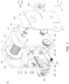
- FIG. 1 is a perspective view of a wire transfer device according to an exemplary embodiment
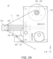
- FIG. 2A is a side view of the wire transfer device according to an exemplary embodiment
- FIG. 2B is a top view of the wire transfer device according to an exemplary embodiment
- FIG. 2C is a front view of the wire transfer device according to an exemplary embodiment.
- a wire transfer device 10 may include a frame 100, a bobbin 200, a tension adjustment unit 300, an encoder module 400, and a driving device 500.
- the wire transfer device 10 may move a wire 11.
- the wire transfer device 10 may transfer the wire which may be connected to foil used in manufacturing a battery.
- the frame 100 may accommodate at least some of components of the wire transfer device 10.
- the bobbin 200, the tension adjustment unit 300, the encoder module 400, and the driving device 500 may be connected directly or indirectly to the frame 100.
- some (e.g., guide roller 600) of the components of the wire transfer device 10 may be disposed outside the frame 100.
- the frame 100 may connect or fix the wire transfer device 10 to a foil transfer device (e.g., foil transfer device 20 in FIG. 4 ).
- a foil transfer device e.g., foil transfer device 20 in FIG. 4
- the frame 100 may be mounted on the foil transfer device by using a coupling component (e.g., screw, magnet, or rivet).
- a coupling component e.g., screw, magnet, or rivet.
- a structure of the frame 100 may be an example and selectively designed.
- the frame 100 may include a chain drive frame 110 accommodating at least a portion of the driving device 500.
- the chain drive frame 110 may support at least one pulley 520 of the driving device 500. At least a portion of at least one pulley 520 may be covered by the frame 100.
- the bobbin 200 may accommodate the wire 11.
- the wire 11 may be wound on the bobbin 200.
- the bobbin 200 may be referred to as a roll or a wire roll.
- the bobbin 200 may include an accommodation region 210 where the wire 11 is configured to be wound and a bobbin drive shaft 220 extending from the accommodation region 210.
- the bobbin drive shaft 220 may be rotatably connected to the frame 100.
- the bobbin drive shaft 220 may include a connection part 221 connected to a chain.
- the frame 100 may include a through-hole 101 for accommodating the bobbin drive shaft 220 of the bobbin 200.
- the wire transfer device 10 may include a brake 230 connected to the bobbin drive shaft 220.
- the brake 230 may prevent the wire 11 from being loosened by preventing rotation of the bobbin 200 when power to a motor 510 is cut off.
- the brake 230 may be a powder brake.
- the wire transfer device 10 may include a bearing structure (not shown) for reducing friction occurring between the bobbin drive shaft 220 and the frame 100.
- the wire transfer device 10 may include the tension adjustment unit 300.
- the tension adjustment unit 300 may stop an operation of the wire transfer device 10 when momentary tension occurs in the wire 11 while the wire 11 is being transferred.
- the tension adjustment unit 300 may include a tension adjustment device 310 and a tension adjustment rack 330 which are connected to the frame 100.
- the tension adjustment rack 330 may be moved by a tension of the wire 11.
- the tension adjustment rack 330 may be moved in a first direction (e.g., -X direction) when the tension of a specified magnitude or more is delivered to the wire 11.
- the tension adjustment device 310 may stop the movement of the wire transfer device 10 when the tension adjustment rack 330 is moved to a specified length or more.
- a rotation speed of the bobbin 200 may be detected or determined based on a length by which the tension adjustment rack 330 is moved in the first direction.
- the tension adjustment device 310 may stop the movement of the wire transfer device 10 when the rotation speed of the bobbin 200 that is detected by the tension adjustment device 310 is a set rotation speed or more.
- the tension adjustment unit 300 may include a screw structure 320.
- the screw structure 320 may move the tension adjustment device 310.
- the screw structure 320 may move the tension adjustment device 310 in a second direction (e.g., Y-axis direction) perpendicular to the first direction.
- a location of the wire 11 wound around the bobbin 200 may be changed as the screw structure 320 is moved in the second direction.
- the wire 11 may be wound substantially uniformly around the bobbin 200 based on the movement of the screw structure 320.
- at least a portion of the wire 11 may be moved after passing the screw structure 320.
- the screw structure 320 may be a reverse screw.
- the tension adjustment unit 300 may include a gas lift 340.
- the gas lift 340 may provide the tension to the wire 11.
- the gas lift 340 may change the tension of the wire 11 by protruding from the frame 100 and/or the tension adjustment device 310 by using a hydraulic pressure.
- the tension adjustment unit 300 may include a linear shaft 350 protruding from the frame 100 and/or the tension adjustment device 310.
- the linear shaft 350 may support at least a portion of the encoder module 400.
- the tension adjustment device 310 may adjust the tension of the wire 11 by changing protruding lengths of the gas lift 340 and the linear shaft 350.
- the wire transfer device 10 may include the encoder module 400 for detecting a transfer amount of the wire 11.
- the encoder module 400 may include an encoder bracket 430 connected to the linear shaft 350, an encoder roller 420 guiding the movement of the wire 11, and an encoder 410 detecting the rotation speed and/or rotation direction of the encoder roller 420.
- the encoder 410 and/or the encoder roller 420 may be connected to the encoder bracket 430.
- the wire transfer device 10 may include the driving device 500.
- the driving device 500 may include the motor 510 providing driving force.
- the motor 510 may be disposed on the frame 100.
- the motor 510 may supply the driving force for rotating the bobbin 200.
- the driving device 500 may include at least one pulley 520 rotatably connected to the frame 100, and the chain connected to at least one pulley 520 and the bobbin 200. At least a portion of the driving force generated by the motor 510 may be delivered to the bobbin 200 through at least one pulley 520 and the chain.
- the chain may be connected to the drive shaft 220 of the bobbin 200.
- the drive shaft 220 may include the connection part 221 accommodating the chain. At least portions of at least one pulley 520 and the chain may be covered by the chain drive frame 110.
- the wire transfer device 10 may include a communications module (not shown) and/or a processor (not shown) for driving the motor 510.
- the communications module may receive a signal delivered in a wireless or wired manner from an external electronic device or server located outside the wire transfer device 10.
- the processor may generate a signal for operating the motor 510 based on the signal received by the communications module.
- the wire transfer device 10 may include a limit sensor (not shown).
- the limit sensor may detect a component (e.g., wire 11 or holder 700) of the wire transfer device 10 that is disposed at a specified point.
- the motor 510 may be operated based on information detected by the limit sensor. For example, the motor 510 may be stopped when the wire 11 or the holder 700 is disposed at the specified point.
- the limit sensor may be replaced by a proximity sensor.
- FIG. 3 is a view of the wire transfer device mounted on the foil transfer device according to an exemplary embodiment
- FIG. 4 is an enlarged view of region A of FIG. 3 according to an exemplary embodiment
- FIG. 5 is an enlarged view of region B of FIG. 3 according to an exemplary embodiment
- FIG. 6 is an enlarged view of region C of FIG. 4 according to an exemplary embodiment.
- the wire transfer device 10 may be used to align foil 21 of the foil transfer device 20.
- Descriptions of the components (e.g., frame 100, bobbin 200, tension adjustment unit 300, encoder module 400, and driving device 500) of the wire transfer device 10 shown in FIGS. 1 , 2A , 2B and/or 2C may also be applied to those of the wire transfer device 10 shown in FIGS. 3 and 4 .
- the wire transfer device 10 may be mounted on the foil transfer device 20.
- the foil transfer device 20 may include a roll (not shown) for transferring the foil 21 and a structure 22 supporting the roll.
- the frame 100 of the wire transfer device 10 may be mounted on the structure 22.
- the foil transfer device 20 may be a manufacturing device used to coat the foil 21.
- the plurality of wire transfer devices 10 may be provided.
- the wire transfer device 10 may include a first wire transfer device 10a disposed on one side (e.g., the left side) of the foil transfer device 20 and a second wire transfer device 10b disposed on the other side (e.g., the right side) of the foil transfer device 20.
- a location of the foil 21 may be aligned as the first wire transfer device 10a and the second wire transfer device 10b pull both ends of the foil 21.
- the wire transfer device 10 may move the foil 21 disposed in an empty space 23 to a path for manufacturing the battery when the foil 21 is moved in the empty space 23 between the structures 22 of the foil transfer device 20.
- the wire transfer device 10 may include at least one guide member 120.
- the guide member 120 may include a roller.
- the guide member 120 may guide the path of the wire 11 withdrawn from the wire transfer device 10.
- the wire 11 wound on the bobbin 200 may be delivered to the guide roller 600 after passing at least one guide member 120.
- the guide member 120 may be disposed on the frame 100.
- the wire transfer device 10 may include the guide roller 600.
- the guide roller 600 may guide the movement of the wire 11 and/or the holder 700.
- the guide roller 600 may be in contact with the wire 11 and/or the holder 700.
- the wire 11 and/or the holder 700 may be moved to the bobbin 200 along a path provided by the guide roller 600.
- the guide roller 600 may be referred to as a bearing.
- the guide roller 600 may include a plurality of guide rollers 610, 620, and 630.
- the guide roller 600 may include the first guide roller 610, the second guide roller 620, and the third guide roller 630 spaced apart from one another.
- the tension delivered to the foil 21 may be changed based on the shape and/or placement of the guide roller 600.
- the description below describes the shape and/or placement of the guide roller 600 in detail with respect to FIGS. 7A through 9B .
- the guide roller 600 may be manufactured using a heat-resistant material.
- the wire transfer device 10 may be used in a high temperature environment.
- the wire transfer device 10 may be manufactured using a material which may be used without lubricant to prevent hardening of the lubricant.
- the guide roller 600 may be formed of a ceramic.
- the guide roller 600 may be spaced apart from the frame 100 of the wire transfer device 10.
- the guide roller 600 may be mounted on the structure 22 of the foil transfer device 20 by using a support member 640 spaced apart from the frame 100.
- At least one guide roller 600 may be provided for one wire transfer device 10.
- the guide roller 600 may include a first roller module 600a disposed outside the structure 22 of the foil transfer device 20 and a second roller module 600b disposed in the structure 22.
- FIG. 4 shows that each of the first roller module 600a and the second roller module 600b includes three guide rollers, and a structure of the guide roller 600 is not limited to thereto.
- each of a first roller module 800a and a second roller module 800b may include two guide rollers.
- the first roller module 600a may include three guide rollers
- the second roller module 600b may include two guide rollers.
- the wire transfer device 10 may include the holder 700 connecting the wire 11 and the foil 21 to each other.
- the holder 700 may include a first end 701 connected to the wire 11 and a second end 702 connected to the foil 21.
- the first end 701 may be connected to the wire 11 by using a coupling component 703 (e.g., pin, rivet, or bolt).
- the second end 702 may be attached to the foil 21 by using an adhesive member (e.g., tape) that is not shown.
- the holder 700 may be referred to as a foil fixation unit.
- the wire 11 may be wound around the bobbin 200 by the wire transfer device 10.
- the holder 700 and the foil 21 may be moved to the wire transfer device 10. Referring to FIG. 4 , the holder 700 may be moved from a holder 700a at a first point to a holder 700b at a second point after passing the guide roller 600.
- the wire 11 and the foil 21 moved by the holder 700 may be moved back to its location for manufacturing the battery (e.g., its location for coating battery electrodes).
- FIGS. 7A and 7B are views of the guide roller according to an exemplary embodiment
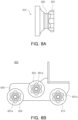
- FIGS. 8A and 8B are views of the guide roller according to another exemplary embodiment
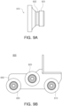
- FIGS. 9A and 9B are views of the guide roller according to another exemplary embodiment.
- Each of FIGS. 7A , 8A , and 9A is a side view of a part (e.g., first guide roller 610) of the guide roller 600.
- the guide roller 600 may be designed in various shapes.
- the description of the guide roller 600 shown in FIGS. 4 and 6 may also be applied to that of the guide roller 600 shown in FIGS. 7A, 7B , 8A, 8B , 9A , and/or 9B.
- the guide roller 600 may provide the movement path of the wire 11 or the holder 700.
- the guide roller 600 may include a protruding region 601 for providing the movement path of the holder 700 and a groove region 602 extending from the protruding region 601 to accommodate the wire 11.
- the holder 700 may be moved while being in contact with the protruding region 601.
- a shape of the protruding region 601 may be selectively designed.
- the protruding region 601 may include a plurality of protrusions 601a in contact with the holder 700.
- the plurality of protrusions 601a may be spaced apart from each other.
- the plurality of protrusions 601a may each include a curved surface surrounding at least a portion (e.g., side surface) of the holder 700.
- the curvature and/or shape of the protrusion 601a may be selectively designed to adjust the tension(s) of the wire 11 and/or the foil 21.
- the protrusion 601a may surround at least a portion of the holder 700.
- the guide roller 600 may include the protrusion 601a protruding substantially in a star shape.
- the guide roller 600 may include the protrusion 601a protruding substantially in a flower shape.
- FIGS. 8A and 8B may include the protrusion 601a protruding substantially in a flower shape.
- the guide roller 600 may include the protruding region 601 protruding substantially in a circular shape.
- the shape of the protrusion 601a shown in FIGS. 7A through 9B may be selectively designed.
- the shape of the protrusion 601a may be changed as long as the structure is to adjust the tension(s) of the wire 11 and/or the foil 21.
- the groove region 602 may have a slit or recess shape to accommodate the wire 11. For example, the wire 11 may be moved while being inserted into the groove region 602.
- the guide rollers 600 may be arranged to have an angle for adjusting the tension(s) of the wire 11 and/or the foil 21.
- the first guide roller 610, the second guide roller 620, and the third guide roller 630 may be arranged to have a specified angle with respect to one another.
- the first guide roller 610, the second guide roller 620, and the third guide roller 630 may have substantially the same shape.
- a specified angle X between a first virtual line L1 and a second virtual line L2 may be set to a range for adjusting the tension(s) of the wire 11 and/or the foil 21, the first virtual line L1 passing through the center of the first guide roller 610 and the center of the second guide roller 620, and the second virtual line L2 passing through the center (e.g., rotation axis) of the first guide roller 610 and the center of the third guide roller 630.
- the second virtual line L2 may be inclined at the specified angle X with respect to the first virtual line L1.
- the specified angle X may be about 20 to 25 degrees.
- the tension(s) of the wire 11 and/or the foil 21 may be set to a desired range by forming the specified angle X to be 20 to 25 degrees. For example, breakage of the wire 11 and/or the foil 21 may be prevented.
- the specified angle X may be 21 to 23 degrees.
- the tension(s) of the wire 11 and/or the foil 21 may be increased as the specified angle X is increased.
- the specified angle X is less than 20 degrees, the tension(s) of the wire 11 and the foil 21 may be increased, thus making it difficult to adjust the location (s) of the wire 11 and/or the foil 21.
- the specified angle X is more than 25 degrees, the wire 11 and/or the foil 21 may be deviated from the path(s).
- the guide rollers 600 may be arranged while having a distance for adjusting the tension(s) of the wire 11 and/or the foil 21.
- a first distance d1 between the center of the first guide roller 610 and the center of the second guide roller 620 may be set to a range for adjusting the tension (s) of the wire 11 and/or the foil 21.
- the first distance d1 may be set to 40 mm to 50 mm.
- the tension(s) of the wire 11 and/or the foil 21 may be set to the desirable range by setting the first distance d1 to 40 mm to 50 mm. For example, the breakage of the wire 11 and/or the foil 21 may be prevented.
- the angle and distance of the guide rollers 600 described with reference to FIG. 7B may also be applied to the guide roller 600 shown in FIG. 8B or 9B .
- FIG. 10 is a front view of the guide roller mounted on the foil transfer device according to an exemplary embodiment
- FIG. 11 is a perspective view of the guide roller mounted on the foil transfer device according to an exemplary embodiment.
- a guide roller 800 may be mounted on the foil transfer device 20. At least a portion of the description of the guide roller 600 described with reference to FIGS. 4 , 6 , and 7A to 9B may also be applied to that of the guide roller 800 shown in FIG(S). 10 and/or 11. For example, the descriptions of the first guide roller 610, the second guide roller 620, and the support member 640 shown in FIG. 6 or 7B may also be applied to those of a first guide roller 810, a second guide roller 820, and a support member 840.
- the number of rollers included in the guide roller 800 may be selectively designed.
- the guide roller 800 may include a first roller module 800a and a second roller module 800b, each including two guide rollers.
- the roller module 800a or 800b may include the first guide roller 810 and the second guide roller 820 spaced apart from the first guide roller 810.
- the first roller module 800a may be symmetric to the second roller module 800b.
- Each of the first guide roller 810 and the second guide roller 820 may include a protruding region 801 for guiding the path of the holder (e.g., holder 700 shown in FIG. 5 ) and a groove region 802 for guiding the path of the wire 11.
- the guide roller 800 may include a support member 840 coupling the first guide roller 810 and the second guide roller 820 to the foil transfer device 20.
- the support member 840 may include at least one fastening part 841.
- the fastening part 841 may include a bolt or a nut.
- the breakage of the foil may be prevented by providing the foil with the tension in the specified range.
- the work convenience may be increased and the safety accident may be prevented.
Landscapes
- Engineering & Computer Science (AREA)
- Manufacturing & Machinery (AREA)
- Chemical & Material Sciences (AREA)
- Chemical Kinetics & Catalysis (AREA)
- Electrochemistry (AREA)
- General Chemical & Material Sciences (AREA)
- Tension Adjustment In Filamentary Materials (AREA)
- Transmission Devices (AREA)
- Registering, Tensioning, Guiding Webs, And Rollers Therefor (AREA)
Abstract
A wire transfer device (10) is provided. The wire transfer device (10) includes a frame (100), a bobbin (200) connected to the frame (100) and on which a wire (11) is configured to be wound; a holder (700) including a first end (701) connected to the wire (11) and a second end (702) opposite to the first end and configured to be connected to foil (21); and a guide roller (600) configured to guide a movement path of the wire (11) or the holder (700). The guide roller (600) includes a groove region (602) for accommodating the wire (11) and a protruding region (601) extending from the groove region (602) and configured to contact with the holder (700).
Description
- The present disclosure relates to a wire transfer device.
- Unlike a primary battery, a secondary battery may be charged and discharged, and thus may be applied to devices within various fields such as a digital camera, a mobile phone, a laptop personal computer (PC), a hybrid vehicle, an electric vehicle, and an energy storage system (ESS). The secondary battery may be a lithium-ion battery, a nickelcadmium battery, a nickel-metal hydride battery, or a nickel-hydrogen battery.
- The secondary battery may be manufactured by a flexible pouch-type battery cell or a rigid prismatic or cylindrical can-type battery cell. The plurality of battery cells may be formed as a stacked cell assembly. The cell assembly may be disposed in a module housing to form a battery module, and the plurality of battery modules may be disposed in a pack housing to form a battery pack. The battery cell may include foil and electrodes coated on the foil.
- The foil may be used to form the anode or cathode of the battery cell. The foil may be transferred from a rolled state to an unfolded state for coating each electrode. However, during a foil transfer process, the foil may be broken due to an external impact or a tension applied to the foil. When the foil is broken, an operator may manually move the broken foil to restart an operation. However, when the operator manually moves the foil, the tension delivered to the foil may not be uniform, based on the operator's level of skill. In addition, heat occurring in a foil transfer device may cause a safety accident to the operator.
- An aspect of the present disclosure may provide a wire transfer device which may provide appropriate tension to foil.
- Another aspect of the present disclosure may provide a wire transfer device which may prevent a safety accident and increase work convenience.
- A battery cell manufactured using the wire transfer device in the present disclosure may be widely applied to devices within the green technology field, such as an electric vehicle, a battery charging station, or solar or wind power generation using battery storage. In addition, a battery cell manufactured using the wire transfer device in the present disclosure may suppress air pollution and greenhouse gas emissions to thus be used in an eco-friendly electric vehicle, a hybrid vehicle or the like for mitigating the effects of climate change.
- According to an aspect of the present disclosure, a wire transfer device may include: a frame; a bobbin connected to the frame and on which a wire is configured to be wound; a holder including a first end connected to the wire and a second end opposite to the first end and configrued to be connected to foil; and a guide roller configured to guide a movement path of the wire or the holder, wherein the guide roller includes a groove region for accommodating the wire and a protruding region extending from the groove region and configured to contact with the holder.
- The protruding region may include a plurality of protrusions respectively having a curved surface surrounding at least a portion of the holder.
- The guide roller may include a first guide roller, a second guide roller, and a third guide roller spaced apart from one another, and a second virtual line passing through a center of the first guide roller and a center of the third guide roller may be inclined at a specified angle with respect to a first virtual line passing through the center of the first guide roller and a center of the second guide roller.
- The specified angle may be 20 to 25 degrees.
- The device may further include a driving device including a motor configured to supply driving force for rotating the bobbin.
- The driving device may include at least one pulley configured to rotate by the driving force generated by the motor, and a chain connected to the at least one pulley and the bobbin, and the frame may include a chain drive frame supporting the at least one pulley.
- The device may further include a limit sensor configured to detect a movement of the wire, wherein the motor is configured to operate based on information detected by the limit sensor.
- The device may further include a tension adjustment unit configured to adjust tension of the wire, wherein the tension adjustment unit includes a tension adjustment rack configured to move by the tension of the wire in a first direction, a tension adjustment device configured to prevent the movement of the tension adjustment rack in the first direction, and a gas lift for increasing the tension of the wire.
- The device may further include an encoder module including an encoder bracket connected to a linear shaft of the tension adjustment unit, an encoder roller connected to the encoder bracket and configured to guide a movement of the wire, and an encoder configured to detect a rotation speed of the encoder roller.
- The tension adjustment unit is connected to the frame, and the tension adjustment unit includes a screw structure for moving the tension adjustment device in a second direction perpendicular to the first direction.
- The bobbin may include an accommodation region for accommodating the wire, and a bobbin drive shaft extending from the accommodation region and rotatably connected to the frame.
- The device may further include a brake connected to the bobbin drive shaft.
- The frame and the guide roller may be configured to be mounted on a foil transfer device while being spaced apart from each other.
- The guide roller may include a ceramic.
- The guide roller may include a first roller module disposed outside a structure of the foil transfer device and a second roller module disposed inside the structure of the foil transfer device.
- The above and other aspects, features, and advantages of the present disclosure will be more clearly understood from the following detailed description taken in conjunction with the accompanying drawings, in which:
-
FIG. 1 is a perspective view of a wire transfer device according to an exemplary embodiment; -
FIG. 2A is a side view of the wire transfer device according to an exemplary embodiment; -
FIG. 2B is a top view of the wire transfer device according to an exemplary embodiment; -
FIG. 2C is a front view of the wire transfer device according to an exemplary embodiment; -
FIG. 3 is a view of the wire transfer device mounted on a foil transfer device according to an exemplary embodiment; -
FIG. 4 is an enlarged view of region A ofFIG. 3 according to an exemplary embodiment; -
FIG. 5 is an enlarged view of region B ofFIG. 3 according to an exemplary embodiment; -
FIG. 6 is an enlarged view of region C ofFIG. 4 according to an exemplary embodiment; -
FIGS. 7A and 7B are views of a guide roller according to an exemplary embodiment; -
FIGS. 8A and 8B are views of a guide roller according to another exemplary embodiment; -
FIGS. 9A and 9B are views of a guide roller according to another exemplary embodiment; -
FIG. 10 is a front view of the guide roller mounted on the foil transfer device according to an exemplary embodiment; and -
FIG. 11 is a perspective view of the guide roller according to an exemplary embodiment. - Hereinafter, exemplary embodiments of the present disclosure will now be described in detail with reference to the accompanying drawings.
-
FIG. 1 is a perspective view of a wire transfer device according to an exemplary embodiment;FIG. 2A is a side view of the wire transfer device according to an exemplary embodiment;FIG. 2B is a top view of the wire transfer device according to an exemplary embodiment; andFIG. 2C is a front view of the wire transfer device according to an exemplary embodiment. - Referring to
FIGS. 1 ,2A ,2B , and/or 2C, awire transfer device 10 may include aframe 100, abobbin 200, atension adjustment unit 300, anencoder module 400, and adriving device 500. - The
wire transfer device 10 may move awire 11. For example, thewire transfer device 10 may transfer the wire which may be connected to foil used in manufacturing a battery. - According to an exemplary embodiment, the
frame 100 may accommodate at least some of components of thewire transfer device 10. For example, thebobbin 200, thetension adjustment unit 300, theencoder module 400, and thedriving device 500 may be connected directly or indirectly to theframe 100. According to an exemplary embodiment, some (e.g., guide roller 600) of the components of thewire transfer device 10 may be disposed outside theframe 100. - According to an exemplary embodiment, the
frame 100 may connect or fix thewire transfer device 10 to a foil transfer device (e.g.,foil transfer device 20 inFIG. 4 ). For example, theframe 100 may be mounted on the foil transfer device by using a coupling component (e.g., screw, magnet, or rivet). According to an exemplary embodiment, a structure of theframe 100 may be an example and selectively designed. - According to an exemplary embodiment, the
frame 100 may include achain drive frame 110 accommodating at least a portion of thedriving device 500. Thechain drive frame 110 may support at least onepulley 520 of thedriving device 500. At least a portion of at least onepulley 520 may be covered by theframe 100. - The
bobbin 200 may accommodate thewire 11. For example, thewire 11 may be wound on thebobbin 200. In an exemplary embodiment, thebobbin 200 may be referred to as a roll or a wire roll. - The
bobbin 200 may include anaccommodation region 210 where thewire 11 is configured to be wound and abobbin drive shaft 220 extending from theaccommodation region 210. Thebobbin drive shaft 220 may be rotatably connected to theframe 100. Thebobbin drive shaft 220 may include aconnection part 221 connected to a chain. According to an exemplary embodiment, theframe 100 may include a through-hole 101 for accommodating thebobbin drive shaft 220 of thebobbin 200. - According to an exemplary embodiment, the
wire transfer device 10 may include abrake 230 connected to thebobbin drive shaft 220. Thebrake 230 may prevent thewire 11 from being loosened by preventing rotation of thebobbin 200 when power to amotor 510 is cut off. In an exemplary embodiment, thebrake 230 may be a powder brake. - In an exemplary embodiment, the
wire transfer device 10 may include a bearing structure (not shown) for reducing friction occurring between thebobbin drive shaft 220 and theframe 100. - According to an exemplary embodiment, the
wire transfer device 10 may include thetension adjustment unit 300. Thetension adjustment unit 300 may stop an operation of thewire transfer device 10 when momentary tension occurs in thewire 11 while thewire 11 is being transferred. - According to an exemplary embodiment, the
tension adjustment unit 300 may include atension adjustment device 310 and atension adjustment rack 330 which are connected to theframe 100. Thetension adjustment rack 330 may be moved by a tension of thewire 11. For example, thetension adjustment rack 330 may be moved in a first direction (e.g., -X direction) when the tension of a specified magnitude or more is delivered to thewire 11. Thetension adjustment device 310 may stop the movement of thewire transfer device 10 when thetension adjustment rack 330 is moved to a specified length or more. For example, a rotation speed of thebobbin 200 may be detected or determined based on a length by which thetension adjustment rack 330 is moved in the first direction. Thetension adjustment device 310 may stop the movement of thewire transfer device 10 when the rotation speed of thebobbin 200 that is detected by thetension adjustment device 310 is a set rotation speed or more. - According to an exemplary embodiment, the
tension adjustment unit 300 may include ascrew structure 320. Thescrew structure 320 may move thetension adjustment device 310. For example, thescrew structure 320 may move thetension adjustment device 310 in a second direction (e.g., Y-axis direction) perpendicular to the first direction. A location of thewire 11 wound around thebobbin 200 may be changed as thescrew structure 320 is moved in the second direction. For example, thewire 11 may be wound substantially uniformly around thebobbin 200 based on the movement of thescrew structure 320. According to an exemplary embodiment, at least a portion of thewire 11 may be moved after passing thescrew structure 320. In an exemplary embodiment, thescrew structure 320 may be a reverse screw. - According to an exemplary embodiment, the
tension adjustment unit 300 may include agas lift 340. According to an exemplary embodiment, thegas lift 340 may provide the tension to thewire 11. For example, thegas lift 340 may change the tension of thewire 11 by protruding from theframe 100 and/or thetension adjustment device 310 by using a hydraulic pressure. - According to an exemplary embodiment, the
tension adjustment unit 300 may include alinear shaft 350 protruding from theframe 100 and/or thetension adjustment device 310. Thelinear shaft 350 may support at least a portion of theencoder module 400. - According to an exemplary embodiment, the
tension adjustment device 310 may adjust the tension of thewire 11 by changing protruding lengths of thegas lift 340 and thelinear shaft 350. - According to an exemplary embodiment, the
wire transfer device 10 may include theencoder module 400 for detecting a transfer amount of thewire 11. For example, theencoder module 400 may include anencoder bracket 430 connected to thelinear shaft 350, anencoder roller 420 guiding the movement of thewire 11, and anencoder 410 detecting the rotation speed and/or rotation direction of theencoder roller 420. Theencoder 410 and/or theencoder roller 420 may be connected to theencoder bracket 430. - According to an exemplary embodiment, the
wire transfer device 10 may include thedriving device 500. - In an exemplary embodiment, the driving
device 500 may include themotor 510 providing driving force. Themotor 510 may be disposed on theframe 100. Themotor 510 may supply the driving force for rotating thebobbin 200. - For example, the driving
device 500 may include at least onepulley 520 rotatably connected to theframe 100, and the chain connected to at least onepulley 520 and thebobbin 200. At least a portion of the driving force generated by themotor 510 may be delivered to thebobbin 200 through at least onepulley 520 and the chain. According to an exemplary embodiment, the chainmay be connected to thedrive shaft 220 of thebobbin 200. For example, thedrive shaft 220 may include theconnection part 221 accommodating the chain. At least portions of at least onepulley 520 and the chain may be covered by thechain drive frame 110. - According to an exemplary embodiment, the
wire transfer device 10 may include a communications module (not shown) and/or a processor (not shown) for driving themotor 510. The communications module may receive a signal delivered in a wireless or wired manner from an external electronic device or server located outside thewire transfer device 10. The processor may generate a signal for operating themotor 510 based on the signal received by the communications module. - According to an exemplary embodiment, the
wire transfer device 10 may include a limit sensor (not shown). The limit sensor may detect a component (e.g.,wire 11 or holder 700) of thewire transfer device 10 that is disposed at a specified point. Themotor 510 may be operated based on information detected by the limit sensor. For example, themotor 510 may be stopped when thewire 11 or theholder 700 is disposed at the specified point. According to an exemplary embodiment, the limit sensor may be replaced by a proximity sensor. -
FIG. 3 is a view of the wire transfer device mounted on the foil transfer device according to an exemplary embodiment;FIG. 4 is an enlarged view of region A ofFIG. 3 according to an exemplary embodiment;FIG. 5 is an enlarged view of region B ofFIG. 3 according to an exemplary embodiment; andFIG. 6 is an enlarged view of region C ofFIG. 4 according to an exemplary embodiment. - Referring to
FIGS. 3 ,4 ,5 and/or 6, thewire transfer device 10 may be used to alignfoil 21 of thefoil transfer device 20. Descriptions of the components (e.g.,frame 100,bobbin 200,tension adjustment unit 300,encoder module 400, and driving device 500) of thewire transfer device 10 shown inFIGS. 1 ,2A ,2B and/or 2C may also be applied to those of thewire transfer device 10 shown inFIGS. 3 and4 . - The
wire transfer device 10 may be mounted on thefoil transfer device 20. Thefoil transfer device 20 may include a roll (not shown) for transferring thefoil 21 and astructure 22 supporting the roll. Theframe 100 of thewire transfer device 10 may be mounted on thestructure 22. In an exemplary embodiment, thefoil transfer device 20 may be a manufacturing device used to coat thefoil 21. - According to an exemplary embodiment, the plurality of
wire transfer devices 10 may be provided. For example, thewire transfer device 10 may include a firstwire transfer device 10a disposed on one side (e.g., the left side) of thefoil transfer device 20 and a secondwire transfer device 10b disposed on the other side (e.g., the right side) of thefoil transfer device 20. A location of thefoil 21 may be aligned as the firstwire transfer device 10a and the secondwire transfer device 10b pull both ends of thefoil 21. For example, thewire transfer device 10 may move thefoil 21 disposed in anempty space 23 to a path for manufacturing the battery when thefoil 21 is moved in theempty space 23 between thestructures 22 of thefoil transfer device 20. - According to an exemplary embodiment, the
wire transfer device 10 may include at least oneguide member 120. Theguide member 120 may include a roller. For example, theguide member 120 may guide the path of thewire 11 withdrawn from thewire transfer device 10. Thewire 11 wound on thebobbin 200 may be delivered to theguide roller 600 after passing at least oneguide member 120. According to an exemplary embodiment, theguide member 120 may be disposed on theframe 100. - The
wire transfer device 10 may include theguide roller 600. Theguide roller 600 may guide the movement of thewire 11 and/or theholder 700. For example, theguide roller 600 may be in contact with thewire 11 and/or theholder 700. Thewire 11 and/or theholder 700 may be moved to thebobbin 200 along a path provided by theguide roller 600. According to an exemplary embodiment, theguide roller 600 may be referred to as a bearing. - According to an exemplary embodiment, the
guide roller 600 may include a plurality ofguide rollers guide roller 600 may include thefirst guide roller 610, thesecond guide roller 620, and thethird guide roller 630 spaced apart from one another. The tension delivered to thefoil 21 may be changed based on the shape and/or placement of theguide roller 600. The description below describes the shape and/or placement of theguide roller 600 in detail with respect toFIGS. 7A through 9B . - According to an exemplary embodiment, the
guide roller 600 may be manufactured using a heat-resistant material. According to an exemplary embodiment, thewire transfer device 10 may be used in a high temperature environment. Thewire transfer device 10 may be manufactured using a material which may be used without lubricant to prevent hardening of the lubricant. For example, theguide roller 600 may be formed of a ceramic. - According to an exemplary embodiment, the
guide roller 600 may be spaced apart from theframe 100 of thewire transfer device 10. For example, theguide roller 600 may be mounted on thestructure 22 of thefoil transfer device 20 by using asupport member 640 spaced apart from theframe 100. - According to an exemplary embodiment, at least one
guide roller 600 may be provided for onewire transfer device 10. For example, theguide roller 600 may include afirst roller module 600a disposed outside thestructure 22 of thefoil transfer device 20 and asecond roller module 600b disposed in thestructure 22. -
FIG. 4 shows that each of thefirst roller module 600a and thesecond roller module 600b includes three guide rollers, and a structure of theguide roller 600 is not limited to thereto. For example, in an exemplary embodiment (e.g., shown inFIG. 10 ), each of afirst roller module 800a and asecond roller module 800b may include two guide rollers. In another exemplary embodiment that is not shown, thefirst roller module 600a may include three guide rollers, and thesecond roller module 600b may include two guide rollers. - The
wire transfer device 10 may include theholder 700 connecting thewire 11 and thefoil 21 to each other. According to an exemplary embodiment, theholder 700 may include afirst end 701 connected to thewire 11 and asecond end 702 connected to thefoil 21. For example, thefirst end 701 may be connected to thewire 11 by using a coupling component 703 (e.g., pin, rivet, or bolt). Thesecond end 702 may be attached to thefoil 21 by using an adhesive member (e.g., tape) that is not shown. In an exemplary embodiment, theholder 700 may be referred to as a foil fixation unit. - The
wire 11 may be wound around thebobbin 200 by thewire transfer device 10. Theholder 700 and thefoil 21 may be moved to thewire transfer device 10. Referring toFIG. 4 , theholder 700 may be moved from a holder 700a at a first point to aholder 700b at a second point after passing theguide roller 600. Thewire 11 and thefoil 21 moved by theholder 700 may be moved back to its location for manufacturing the battery (e.g., its location for coating battery electrodes). -
FIGS. 7A and 7B are views of the guide roller according to an exemplary embodiment;FIGS. 8A and 8B are views of the guide roller according to another exemplary embodiment; andFIGS. 9A and 9B are views of the guide roller according to another exemplary embodiment. Each ofFIGS. 7A ,8A , and9A is a side view of a part (e.g., first guide roller 610) of theguide roller 600. - Referring to
FIGS. 7A, 7B ,8A, 8B ,9A and/or 9B, theguide roller 600 may be designed in various shapes. The description of theguide roller 600 shown inFIGS. 4 and6 may also be applied to that of theguide roller 600 shown inFIGS. 7A, 7B ,8A, 8B ,9A , and/or 9B. - The
guide roller 600 may provide the movement path of thewire 11 or theholder 700. For example, theguide roller 600 may include aprotruding region 601 for providing the movement path of theholder 700 and agroove region 602 extending from theprotruding region 601 to accommodate thewire 11. For example, theholder 700 may be moved while being in contact with theprotruding region 601. - A shape of the
protruding region 601 may be selectively designed. Referring toFIGS. 7A, 7B ,8A, and 8B , theprotruding region 601 may include a plurality ofprotrusions 601a in contact with theholder 700. The plurality ofprotrusions 601a may be spaced apart from each other. The plurality ofprotrusions 601a may each include a curved surface surrounding at least a portion (e.g., side surface) of theholder 700. - The curvature and/or shape of the
protrusion 601a may be selectively designed to adjust the tension(s) of thewire 11 and/or thefoil 21. Theprotrusion 601a may surround at least a portion of theholder 700. According to an exemplary embodiment (e.g., shown inFIGS. 7A and 7B ), theguide roller 600 may include theprotrusion 601a protruding substantially in a star shape. According to an exemplary embodiment (e.g., shown inFIGS. 8A and 8B ), theguide roller 600 may include theprotrusion 601a protruding substantially in a flower shape. According to an exemplary embodiment (e.g., shown inFIGS. 9A and 9B ), theguide roller 600 may include theprotruding region 601 protruding substantially in a circular shape. The shape of theprotrusion 601a shown inFIGS. 7A through 9B may be selectively designed. For example, the shape of theprotrusion 601a may be changed as long as the structure is to adjust the tension(s) of thewire 11 and/or thefoil 21. - The
groove region 602 may have a slit or recess shape to accommodate thewire 11. For example, thewire 11 may be moved while being inserted into thegroove region 602. - According to an exemplary embodiment, the
guide rollers 600 may be arranged to have an angle for adjusting the tension(s) of thewire 11 and/or thefoil 21. For example, thefirst guide roller 610, thesecond guide roller 620, and thethird guide roller 630 may be arranged to have a specified angle with respect to one another. In an exemplary embodiment, thefirst guide roller 610, thesecond guide roller 620, and thethird guide roller 630 may have substantially the same shape. - According to an exemplary embodiment, a specified angle X between a first virtual line L1 and a second virtual line L2 may be set to a range for adjusting the tension(s) of the
wire 11 and/or thefoil 21, the first virtual line L1 passing through the center of thefirst guide roller 610 and the center of thesecond guide roller 620, and the second virtual line L2 passing through the center (e.g., rotation axis) of thefirst guide roller 610 and the center of thethird guide roller 630. The second virtual line L2 may be inclined at the specified angle X with respect to the first virtual line L1. According to an exemplary embodiment, the specified angle X may be about 20 to 25 degrees. The tension(s) of thewire 11 and/or thefoil 21 may be set to a desired range by forming the specified angle X to be 20 to 25 degrees. For example, breakage of thewire 11 and/or thefoil 21 may be prevented. In an exemplary embodiment, the specified angle X may be 21 to 23 degrees. - According to an exemplary embodiment, the tension(s) of the
wire 11 and/or thefoil 21 may be increased as the specified angle X is increased. When the specified angle X is less than 20 degrees, the tension(s) of thewire 11 and thefoil 21 may be increased, thus making it difficult to adjust the location (s) of thewire 11 and/or thefoil 21. When the specified angle X is more than 25 degrees, thewire 11 and/or thefoil 21 may be deviated from the path(s). - According to an exemplary embodiment, the
guide rollers 600 may be arranged while having a distance for adjusting the tension(s) of thewire 11 and/or thefoil 21. For example, a first distance d1 between the center of thefirst guide roller 610 and the center of thesecond guide roller 620 may be set to a range for adjusting the tension (s) of thewire 11 and/or thefoil 21. According to an exemplary embodiment, the first distance d1 may be set to 40 mm to 50 mm. The tension(s) of thewire 11 and/or thefoil 21 may be set to the desirable range by setting the first distance d1 to 40 mm to 50 mm. For example, the breakage of thewire 11 and/or thefoil 21 may be prevented. - The angle and distance of the
guide rollers 600 described with reference toFIG. 7B may also be applied to theguide roller 600 shown inFIG. 8B or9B . -
FIG. 10 is a front view of the guide roller mounted on the foil transfer device according to an exemplary embodiment; andFIG. 11 is a perspective view of the guide roller mounted on the foil transfer device according to an exemplary embodiment. - Referring to FIG(S). 10 and/or 11, a
guide roller 800 may be mounted on thefoil transfer device 20. At least a portion of the description of theguide roller 600 described with reference toFIGS. 4 ,6 , and7A to 9B may also be applied to that of theguide roller 800 shown in FIG(S). 10 and/or 11. For example, the descriptions of thefirst guide roller 610, thesecond guide roller 620, and thesupport member 640 shown inFIG. 6 or7B may also be applied to those of afirst guide roller 810, asecond guide roller 820, and asupport member 840. - According to an exemplary embodiment, the number of rollers included in the
guide roller 800 may be selectively designed. For example, theguide roller 800 may include afirst roller module 800a and asecond roller module 800b, each including two guide rollers. - The
roller module first guide roller 810 and thesecond guide roller 820 spaced apart from thefirst guide roller 810. Thefirst roller module 800a may be symmetric to thesecond roller module 800b. - Each of the
first guide roller 810 and thesecond guide roller 820 may include aprotruding region 801 for guiding the path of the holder (e.g.,holder 700 shown inFIG. 5 ) and agroove region 802 for guiding the path of thewire 11. - The
guide roller 800 may include asupport member 840 coupling thefirst guide roller 810 and thesecond guide roller 820 to thefoil transfer device 20. Thesupport member 840 may include at least onefastening part 841. Thefastening part 841 may include a bolt or a nut. - The content described above is only an example to which a principle of the present disclosure is applied, and may further include another configuration within the scope of the present disclosure.
- As set forth above, according to an exemplary embodiment of the present disclosure, the breakage of the foil may be prevented by providing the foil with the tension in the specified range.
- According to an exemplary embodiment of the present disclosure, the work convenience may be increased and the safety accident may be prevented.
- While the exemplary embodiments have been shown and described above, it will be apparent to those skilled in the art that modifications and variations could be made without departing from the scope of the present disclosure as defined by the appended claims.
Claims (15)
- A wire transfer device comprising:a frame;a bobbin connected to the frame and on which a wire is configured to be wound;a holder including a first end connected to the wire and a second end opposite to the first end and configured to be connected to foil; anda guide roller configured to guide a movement path of the wire or the holder,wherein the guide roller includes a groove region for accommodating the wire and a protruding region extending from the groove region and configured to contact with the holder.
- The device of claim 1, wherein the protruding region includes a plurality of protrusions respectively having a curved surface surrounding at least a portion of the holder.
- The device of claims 1 or 2, wherein the guide roller includes a first guide roller, a second guide roller, and a third guide roller spaced apart from one another, and
a second virtual line passing through a center of the first guide roller and a center of the third guide roller is inclined at a specified angle with respect to a first virtual line passing through the center of the first guide roller and a center of the second guide roller. - The device of claim 3, wherein the specified angle is 20 to 25 degrees.
- The device of any one of preceding claims, further comprising a driving device including a motor configured to supply driving force for rotating the bobbin.
- The device of claim 5, wherein the driving device includes at least one pulley configured to rotate by the driving force generated by the motor, and a chain connected to the at least one pulley and the bobbin, and
the frame includes a chain drive frame supporting the at least one pulley. - The device of any of claims 5 or 6, further comprising a limit sensor configured to detect a movement of the wire,
wherein the motor is configured to operate based on information detected by the limit sensor. - The device of any one of preceding claims, further comprising a tension adjustment unit configured to adjust tension of the wire,wherein the tension adjustment unit includesa tension adjustment rack configured to move by the tension of the wire in a first direction,a tension adjustment device configured to prevent the movement of the tension adjustment rack in the first direction, anda gas lift for increasing the tension of the wire.
- The device of claim 8, further comprising an encoder module includingan encoder bracket connected to a linear shaft of the tension adjustment unit,an encoder roller connected to the encoder bracket and configured to guide a movement of the wire, andan encoder configrued to detect a rotation speed of the encoder roller.
- The device of any of claims 8 or 9, wherein the tension adjustment unit is connected to the frame, and the tension adjustment unit includes a screw structure for moving the tension adjustment device in a second direction perpendicular to the first direction.
- The device of any one of preceding claims, wherein the bobbin includesan accommodation region for accommodating the wire, anda bobbin drive shaft extending from the accommodation region and rotatably connected to the frame.
- The device of claim 11, further comprising a brake connected to the bobbin drive shaft.
- The device of any one of preceding claims, wherein the frame and the guide roller are configured to be mounted on a foil transfer device while being spaced apart from each other.
- The device of any one of preceding claims, wherein the guide roller includes a ceramic.
- The device of any one of preceding claims, wherein the guide roller includesa first roller module disposed outside a structure of the foil transfer device anda second roller module disposed inside the structure of the foil transfer device.
Applications Claiming Priority (1)
| Application Number | Priority Date | Filing Date | Title |
|---|---|---|---|
| KR1020230096915A KR20250015466A (en) | 2023-07-25 | 2023-07-25 | Wire transfer device |
Publications (1)
| Publication Number | Publication Date |
|---|---|
| EP4497714A1 true EP4497714A1 (en) | 2025-01-29 |
Family
ID=91962027
Family Applications (1)
| Application Number | Title | Priority Date | Filing Date |
|---|---|---|---|
| EP24189963.2A Pending EP4497714A1 (en) | 2023-07-25 | 2024-07-22 | Wire transfer device |
Country Status (4)
| Country | Link |
|---|---|
| US (1) | US20250033922A1 (en) |
| EP (1) | EP4497714A1 (en) |
| KR (1) | KR20250015466A (en) |
| CN (1) | CN119370671A (en) |
Families Citing this family (1)
| Publication number | Priority date | Publication date | Assignee | Title |
|---|---|---|---|---|
| CN112850363B (en) * | 2021-01-22 | 2022-02-22 | 北京航空航天大学 | Variable-rod-length rigid-flexible coupling mechanism for regulating and controlling tension of fiber bundle |
Citations (1)
| Publication number | Priority date | Publication date | Assignee | Title |
|---|---|---|---|---|
| US20220185620A1 (en) * | 2019-03-27 | 2022-06-16 | Movecat GmbH | Winch comprising a winding device |
-
2023
- 2023-07-25 KR KR1020230096915A patent/KR20250015466A/en active Pending
-
2024
- 2024-07-15 CN CN202410940746.4A patent/CN119370671A/en active Pending
- 2024-07-16 US US18/774,890 patent/US20250033922A1/en active Pending
- 2024-07-22 EP EP24189963.2A patent/EP4497714A1/en active Pending
Patent Citations (1)
| Publication number | Priority date | Publication date | Assignee | Title |
|---|---|---|---|---|
| US20220185620A1 (en) * | 2019-03-27 | 2022-06-16 | Movecat GmbH | Winch comprising a winding device |
Also Published As
| Publication number | Publication date |
|---|---|
| CN119370671A (en) | 2025-01-28 |
| KR20250015466A (en) | 2025-02-03 |
| US20250033922A1 (en) | 2025-01-30 |
Similar Documents
| Publication | Publication Date | Title |
|---|---|---|
| EP4497714A1 (en) | Wire transfer device | |
| KR101921295B1 (en) | Apparatus for manufacturing rechargeable battery | |
| KR20200136198A (en) | Core-Chuck Hybrid Bobin for Manufacturing Electrode | |
| US20250011120A1 (en) | Separator supply device and separator supply method | |
| KR102796439B1 (en) | Secondary battery electrode plate manufacturing device and manufacturing method | |
| KR101835710B1 (en) | Apparatus for insrting pole plate of rechargeable battery | |
| KR102468973B1 (en) | System for producing electrodes of battery | |
| EP4425622A1 (en) | Automatic separator supply device | |
| KR101956935B1 (en) | Electrode plate rolling device and method using the same | |
| KR102438740B1 (en) | Secondary battery electrode film roll-to-sheet device with vibration compensation unit | |
| EP4216326A1 (en) | Battery assembly and processing method and apparatus, battery cell, battery and electric device | |
| KR102513767B1 (en) | System for producing electrodes of battery | |
| KR101165462B1 (en) | Pole plate winding device | |
| CN120734542B (en) | Laser etching equipment and battery production line | |
| EP4425625B1 (en) | Positioning member, winding device for electrode assembly, and battery manufacturing device | |
| EP4734216A1 (en) | Winding needle, winding apparatus, battery manufacturing apparatus, and winding method | |
| KR102940382B1 (en) | Automatic adjustment device for taping device for secondary battery | |
| KR20250065011A (en) | Electrode assembly support device | |
| US20260125234A1 (en) | Winding pin, winding apparatus, battery manufacturing device, and winding method | |
| EP4583214A1 (en) | Electrode sheet heating device, electrode sheet heating method, and jelly roll-type electrode assembly | |
| CA3187318C (en) | Electrode assembly and processing method and apparatus therefor, battery cell, battery, and power consuming device | |
| US20260051629A1 (en) | Secondary battery, battery pack, and electronic device | |
| US20260066329A1 (en) | System and method for manufacturing secondary battery | |
| KR100635706B1 (en) | Pole plate winding device for secondary battery | |
| US20250026597A1 (en) | Automatic Separator Supply Apparatus |
Legal Events
| Date | Code | Title | Description |
|---|---|---|---|
| PUAI | Public reference made under article 153(3) epc to a published international application that has entered the european phase |
Free format text: ORIGINAL CODE: 0009012 |
|
| STAA | Information on the status of an ep patent application or granted ep patent |
Free format text: STATUS: THE APPLICATION HAS BEEN PUBLISHED |
|
| AK | Designated contracting states |
Kind code of ref document: A1 Designated state(s): AL AT BE BG CH CY CZ DE DK EE ES FI FR GB GR HR HU IE IS IT LI LT LU LV MC ME MK MT NL NO PL PT RO RS SE SI SK SM TR |
|
| STAA | Information on the status of an ep patent application or granted ep patent |
Free format text: STATUS: REQUEST FOR EXAMINATION WAS MADE |
|
| 17P | Request for examination filed |
Effective date: 20250725 |