EP4497669A1 - Bicycle - Google Patents
Bicycle Download PDFInfo
- Publication number
- EP4497669A1 EP4497669A1 EP24190525.6A EP24190525A EP4497669A1 EP 4497669 A1 EP4497669 A1 EP 4497669A1 EP 24190525 A EP24190525 A EP 24190525A EP 4497669 A1 EP4497669 A1 EP 4497669A1
- Authority
- EP
- European Patent Office
- Prior art keywords
- bicycle
- chainstay
- upper tube
- tube
- crank
- Prior art date
- Legal status (The legal status is an assumption and is not a legal conclusion. Google has not performed a legal analysis and makes no representation as to the accuracy of the status listed.)
- Granted
Links
Images



Classifications
-
- B—PERFORMING OPERATIONS; TRANSPORTING
- B62—LAND VEHICLES FOR TRAVELLING OTHERWISE THAN ON RAILS
- B62K—CYCLES; CYCLE FRAMES; CYCLE STEERING DEVICES; RIDER-OPERATED TERMINAL CONTROLS SPECIALLY ADAPTED FOR CYCLES; CYCLE AXLE SUSPENSIONS; CYCLE SIDECARS, FORECARS, OR THE LIKE
- B62K3/00—Bicycles
- B62K3/02—Frames
- B62K3/04—Frames having a substantially horizontal top bar
-
- B—PERFORMING OPERATIONS; TRANSPORTING
- B62—LAND VEHICLES FOR TRAVELLING OTHERWISE THAN ON RAILS
- B62K—CYCLES; CYCLE FRAMES; CYCLE STEERING DEVICES; RIDER-OPERATED TERMINAL CONTROLS SPECIALLY ADAPTED FOR CYCLES; CYCLE AXLE SUSPENSIONS; CYCLE SIDECARS, FORECARS, OR THE LIKE
- B62K19/00—Cycle frames
- B62K19/18—Joints between frame members
-
- B—PERFORMING OPERATIONS; TRANSPORTING
- B62—LAND VEHICLES FOR TRAVELLING OTHERWISE THAN ON RAILS
- B62K—CYCLES; CYCLE FRAMES; CYCLE STEERING DEVICES; RIDER-OPERATED TERMINAL CONTROLS SPECIALLY ADAPTED FOR CYCLES; CYCLE AXLE SUSPENSIONS; CYCLE SIDECARS, FORECARS, OR THE LIKE
- B62K25/00—Axle suspensions
- B62K25/04—Axle suspensions for mounting axles resiliently on cycle frame or fork
- B62K25/28—Axle suspensions for mounting axles resiliently on cycle frame or fork with pivoted chain-stay
- B62K25/286—Axle suspensions for mounting axles resiliently on cycle frame or fork with pivoted chain-stay the shock absorber being connected to the chain-stay via a linkage mechanism
-
- B—PERFORMING OPERATIONS; TRANSPORTING
- B62—LAND VEHICLES FOR TRAVELLING OTHERWISE THAN ON RAILS
- B62M—RIDER PROPULSION OF WHEELED VEHICLES OR SLEDGES; POWERED PROPULSION OF SLEDGES OR SINGLE-TRACK CYCLES; TRANSMISSIONS SPECIALLY ADAPTED FOR SUCH VEHICLES
- B62M1/00—Rider propulsion of wheeled vehicles
- B62M1/24—Rider propulsion of wheeled vehicles with reciprocating levers, e.g. foot levers
- B62M1/32—Rider propulsion of wheeled vehicles with reciprocating levers, e.g. foot levers characterised by directly driving the wheel axle, e.g. by using a ratchet wheel
-
- B—PERFORMING OPERATIONS; TRANSPORTING
- B62—LAND VEHICLES FOR TRAVELLING OTHERWISE THAN ON RAILS
- B62K—CYCLES; CYCLE FRAMES; CYCLE STEERING DEVICES; RIDER-OPERATED TERMINAL CONTROLS SPECIALLY ADAPTED FOR CYCLES; CYCLE AXLE SUSPENSIONS; CYCLE SIDECARS, FORECARS, OR THE LIKE
- B62K15/00—Collapsible or foldable cycles
- B62K2015/001—Frames adapted to be easily dismantled
-
- B—PERFORMING OPERATIONS; TRANSPORTING
- B62—LAND VEHICLES FOR TRAVELLING OTHERWISE THAN ON RAILS
- B62M—RIDER PROPULSION OF WHEELED VEHICLES OR SLEDGES; POWERED PROPULSION OF SLEDGES OR SINGLE-TRACK CYCLES; TRANSMISSIONS SPECIALLY ADAPTED FOR SUCH VEHICLES
- B62M1/00—Rider propulsion of wheeled vehicles
- B62M1/24—Rider propulsion of wheeled vehicles with reciprocating levers, e.g. foot levers
- B62M1/28—Rider propulsion of wheeled vehicles with reciprocating levers, e.g. foot levers characterised by the use of flexible drive members, e.g. chains
Definitions
- the invention pertains to the field of bicycles and relates in particular to the manner of their propulsion and to the construction of the frame to make the bicycle compact and able to be disassembled.
- the classic bicycle comprises a frame with a fork, a horizontal rear chainstay, an oblique rear chainstay; an upper tube and a vertical rear tube. Then the following are generally provided: a handlebar on the top of the fork, a saddle, at least two wheels, of which one front wheel hangs in a freely rotatable manner in the fork and one rear wheel is housed on the horizontal rear chainstay, and a transmission unit with two cranks equipped with pedals and connected to a gear wheel which perform a circular movement which is transmitted via a chain from the gear wheel to another gear wheel provided on the hub of the rear wheel.
- the known drive or transmission system does not always allow the construction of a large rear wheel beyond the standard diameters or allow for reducing the force required to pedal without the application of a gear change.
- the object of the invention is to overcome the aforesaid drawbacks and to propose a bicycle that is able to reduce the pedalling effort, for example by providing the possibility of realizing a rear wheel larger than that usually provided in the state of the art.
- a further object of the invention is to provide a compact bicycle.
- Another object of the invention is to provide a bicycle that can be disassembled.
- the aim is achieved by means of a bicycle comprising:
- the intervention by the inventor on the transmission unit made it possible to position the crank system practically in correspondence with the rear wheel and no longer place it between the two wheels. In this way it was possible to lengthen the length of the crank compared to traditional cranks, which gives a greater lever force by reducing the force required to pedal.
- the position and possible increased length of the cranks (e.g. lengths roughly corresponding to the wheel radius ⁇ 5 cm) according to the invention is even better achievable if, in a preferred embodiment of the invention, the saddle is placed on the end of the upper tube directly above the rear wheel.
- a consequence of this configuration is also the possibility of making large rear wheels, which obviously allows for easy propulsion.
- the gear wheel system directly placed in correspondence with the rear wheel also shortens the length of the chain needed and reduces the danger of it coming out of position.
- the two discs can easily be made with dimensions covering essentially the entire transmission unit.
- the second and third gear wheels are sprockets, therefore first and second sprockets respectively.
- each crank and the respective disc there is a ratchet connection for transmitting the movement of the crank to the respective disc.
- the ratchet allows a controlled articulation of the crank, prevents the propulsive movement of the same in the unwanted direction, but allows a position of the crank that is not necessarily radial around the axis of rotation of the disc.
- the ratchet connection is installed in such a way that in the direction of the active pedalling it is in the locking position, while during the passive phase of repositioning of the respective crank towards the position of the beginning of the active phase it is in the movement position.
- sprockets in preferred variants of the invention, can also be made with a ratchet system.
- gear wheels, chains, cranks, etc. of the transmission unit are provided in pairs allows their mirrored application on the two sides of the bicycle.
- the second gear wheels have different diameters and for each first gear wheel an engagement/disengagement device is provided to bring the relative first gear wheel closer to/farther from the toothed inner ring of the respective disc.
- an engagement/disengagement device is provided to bring the relative first gear wheel closer to/farther from the toothed inner ring of the respective disc.
- the engagement/disengagement device may, for example, be an electric motor connected with an extractable stem and retractable to the shaft that connects the first to the second gear wheel or to the shaft bearing.
- a threaded rod driven by the electric motor that screws into a support or bearing of the shaft.
- the third gear wheels can also have different diameters.
- crank-gear wheel systems of the left side and the right side alternate in the propulsive and entrainment action.
- a particularly preferred embodiment of the invention provides that said oblique rear chainstay on one end is fixed on said horizontal rear chainstay and on the other end is equipped with an articulated bifurcation which with its two rods is fixed in articulated manner on said upper tube forming a triangle wherein said front rod is equipped with an elastic element.
- the articulations of the bifurcation located at least in two corners of the triangle allow a simple damping of the bicycle during use and also help its foldability.
- the term "horizontal" of the rear chainstay and also of the orientation of the crank during movement is understood as an essentially horizontal extension, that is, with a maximum inclination that preferably does not exceed 30° with respect to a support plane of the two wheels of the bicycle.
- Other terms known in the state of the art for rear horizontal chainstay is dropped chainstay, while the rear oblique chainstay also takes the name vertical chainstay.
- the plural "chainstays" is also used to indicate that the chainstay is generally forked to be able to include the rear wheel.
- the bicycle does not comprise a vertical rear tube (also called a column tube) for connecting said horizontal rear chainstay to said upper tube and the saddle is fixed on said upper tube whose end is not supported by other parts of the frame.
- a vertical rear tube also called a column tube
- the bicycle further comprises (f) a travel stop for each crank comprising:
- the crank is eccentrically fixed to the disc and the pedal during use does not protrude more than 5 cm beyond the rear wheel.
- the crank is mounted at a position on the disc which is located in a portion of the radius of the disc which corresponds to the central third of the radius, for example at half the radius. More advantageous are positions near the centre of the disc, which however are constructively disadvantaged.
- the crank has a length which corresponds at least to the radius of the rear wheel minus the distance between its connection to the disc and the centre of the disc.
- the active and passive phases also alternate in a traditional bicycle, but in the case of a bicycle according to the invention, the effect of application of force by the cyclist is multiplied thanks to the length of the crank made possible by the particular configuration of the bicycle drive system.
- the length of the crank in the bicycle according to the invention may for example reach more than twice the length of a crank of a conventional bicycle.
- the travel stop according to the invention allows the pedal to be practically always in the front half of the wheel or slightly ahead, allowing the cyclist to comfortably reach the pedals in any position.
- the "passive" crank is repositioned more quickly for a new active-positive phase than on a classic bicycle.
- the anchorage of the crank to the disc is located between the central point of the disc and its edge, allows faster repositioning of the crank for a new active-positive phase.
- the ratchet mechanism movable "one-way" that is arranged at the point of anchoring the crank to the disc.
- connection between said rear horizontal chainstay and said curved or oblique tube can be disassembled and said upper tube comprises:
- the system with tubes of different diameters, one insertable in the other, is very simple and allows a quick assembly and disassembly of the bicycle for better transport, for example in the trunk of a car.
- Such an upper closure system with longitudinal tubes that can be inserted one into the other and preferably a closure, for example with a bayonet joint, further guarantees a torsional rigidity of the bicycle frame (unlike standard folding bicycles with hinged systems) to make the force applied by the cyclist more efficient, so as to minimise waste due to the deformation of the frame during pedalling.
- a preferred embodiment of the invention provides an electric version of the bicycle according to the invention, wherein a motor is present, preferably inserted in the rear hub of the bicycle.
- a battery thereof for driving the motor may be provided, for example, in the curved tube.
- a pedal-assisted version which is advantageously foldable and therefore compact in a disassembled version, has a greater autonomy than a traditional e-bike due to a greater efficiency in the pedalling phase thanks to the possible greater length of the crank (up to more than twice that of a standard bicycle) or allows the same autonomy as a standard bicycle to be achieved to reduce the size/power of the battery.
- a further aspect of the invention relates to a process for propelling a bicycle comprising the following steps:
- the two first wheels can have different diameters and engagement/disengagement devices can be provided and operated that engage/disengage a first gear wheel from the toothed ring of the respective disc to change gear.
- the damping means compensate for the irregularities of the supporting surface by compressing and relaxing the elastic elements and deforming and repositioning the bifurcation triangle.
- the articulations are also useful when disassembling the bicycle. Any crank travel stop allows the pedals to follow an essentially oval circuit and force the crank into positions that are temporarily essentially horizontal with respect to a supporting surface of the bicycle.
- the ratchet system allows the transition between the active and passive phases. In phase (V) it is conceivable to insert a gear change between the second and third gear wheel and then connect the chain to the gear change and the third gear wheel.
- said horizontal rear chainstay is connected by fixing means to said curved or oblique tube wherein said fixing means in a state of partial opening allow a rotation of said horizontal rear chainstay and/or said curved tube around the connection axle.
- the horizontal rear chainstay comprises a hollow cylinder through which a screw passes that can be screwed in a compatible thread that is located in the curved tube in a position inside the tube itself, wherein the cylinder continues with a second hollow cylinder outside the horizontal rear chainstay, always crossed by the screw wherein a nut with a hexagonal or other geometry is arranged in the lower part of the second cylinder that is insertable in a hole with a corresponding compatible geometry located in the lower end of the curved or oblique tube to create an initial connection of defined position between the curved tube and the horizontal rear chainstay.
- the second cylinder in the mounted state passes into the lower space of the curved tube, and the screw is screwed into the thread.
- a small elasticity of movement along the height of the nut is advantageously given by a spring inserted on the screw and by the path allowed by the degree of screwing to extract the nut from its hole and allows a rotation of the curved tube around the first cylinder or of the cylinder inside the curved or oblique tube to be able to rotate the front part of the bicycle on the rear one and vice versa without disassembling the curved or oblique tube completely from the horizontal rear chainstay.
- a further aspect of the invention relates to a method for assembling/disassembling a bicycle comprising the following steps:
- the opening of the fixing means between the oblique rear chainstay and the curved or oblique tube can mean a complete detachment between the horizontal rear tube and the curved tube or only a partial detachment that provides for the rotation of the curved or oblique tube with respect to the horizontal rear chainstay or vice versa.
- the succession of steps is not very complex and allows fast mounting and dismounting of the bicycle.
- the extraction of the third upper tube portion from the second upper tube portion could also take place before the phase (iii-3).
- Fig. 1 shows, in a side view, an exemplary embodiment of a bicycle 10 according to the invention.
- Two wheels 12 are noted of which the first (front) one is inserted inside a fork 14.
- the wheels 12 can be equipped with the classic spokes (not shown) and comprise a rim and a tyre (not shown in detail).
- the steering tube 16 carries the handlebar 18.
- the frame comprises an upper tube 20 and a curved tube 22 corresponding to the oblique tube of a classic bicycle.
- the horizontal rear chainstay 26 is connected with the curved tube 22 by a fixing means 28 .
- the upper tube 20 is equipped on one end with the seat post 30 which supports the saddle 32.
- the oblique rear chainstay 24 ends in a kind of bifurcation composed of a rod 34 and an elastic element 36 that together form a triangle with the upper tube 20.
- the pedal 38 is fixed on a crank 40 which in turn is fixed on a disc 42 which, following the movement (arrow A ) of the pedal 38, rotates clockwise (arrow B ). Behind the disc 42 an arm 44 of the crank travel stop system can be seen, which will then be shown with reference to Figs. 4A-C .
- the rod 34 and the elastic element 36 form a damping system of the bicycle 10.
- the horizontal rear chainstay 26 is pushed upwards, resulting in a thrust of the oblique rear chainstay 24 in the direction of its extension towards the upper tube 20.
- the elastic element 36 (for example a spring) is compressed and simultaneously, the rod 34 articulated to the upper tube 20 and to the oblique rear chainstay 24 through respective articulations 46, is moved towards the rear tube 20 reducing the dimensions of the aforementioned triangle. Subsequently, the elastic element 36 relaxes, the rod 34 returns to its initial position, as does the oblique rear chainstay 24.
- Fig. 2 compares the bicycle 10 of Fig. 1 with a traditional bicycle 10' according to the state of the art.
- the saddle 32 is positioned centrally above the rear wheel 12, whereas in the case of the conventional bicycle 10', the saddle 32' is positioned further forward. The same holds for the position of the respective handlebars 18 and 18' with respect to the rear wheel 12, 12'.
- the curved tube 22 of the bicycle 10 essentially corresponds to the cross tube 22' of the bicycle 10'. Except for their inclination, there is correspondence between the upper tubes, respectively 20 and 20'.
- the vertical tube or column 21' is completely missing; the oblique rear chainstay 24 of the bicycle 10 is connected by means of the damping system 34, 36 (which in the traditional bicycle 10' is not provided) to the upper tube 20, while in the traditional bicycle 10' the respective oblique rear chainstay 24' is fixed on the vertical tube 21'.
- the pedals 38 of the bicycle 10 according to the invention practically do not protrude beyond the wheel 12, while the pedals 38' of the bicycle 10' are located between the two wheels 12'.
- the bicycle 10 according to the invention is therefore shorter and more compact than the classic 10' bicycle and allows the construction of longer cranks 40, which is also due to their application in a relatively central position on the rear wheel 12 with an increased leverage effect.
- crank lengths of 34 cm are achievable compared to the 17 cm of the traditional bicycle 10'.
- the frame of the bicycle 10 according to the invention in particular due to the absence of the vertical tube 21', allows, as will be seen below, a simple construction of the disassembly of the bicycle 10.
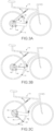
- Figs. 3A-F show in sequence the various drive phases of the bicycle transmission unit 10 of Fig. 1 . Below and in Figures 3A to 3F , only the parts affected by the drive are indicated.
- a cyclist presses the pedal 38 in the direction of the arrow A. Since the pedal 38 is connected in an articulated manner to the disc 42 by means of the crank 40, the disc 42, which is part of the transmission unit of the bicycle 10 also rotates in the direction of the arrow B.
- the transmission unit will be shown with respect to Fig. 8 .
- both the connection between pedal 38 and crank 40 and the connection between crank 40 and disc 42 are articulated.
- the pedal 38 then follows the circumference of the wheel 12 and the crank 40 moves to the second phase ( Fig. 3B ) in an essentially horizontal position. Following the direction of the arrow A, the pedal 38 continues its movement always along the circumference of the wheel 12 to reach the position shown in Fig. 3C (third phase). Due to the travel stop system of which only the arm 44 is visible, the crank 40 is no longer movable in a circular shape around the centre of the wheel 12, but, turning around its articulation with the disc 42, follows the direction of the arrow A and is brought back to an essentially horizontal position to reach the position shown in Fig. 3D (fourth phase). The crank 40 continues to follow practically the direction of the arrow A, while the disc 42 travels during its rotation (arrow B ) about another 90°.
- crank 40 moves from an essentially horizontal position below the horizontal rear chainstay 26 to an essentially horizontal position above it, as shown in the fifth phase ( Fig. 3E ).
- crank 40 follows the crank 40 with its articulation to the disc 42 again an essentially horizontal movement (arrow A ) to the right and then upwards, it returns to the sixth phase ( Fig. 3F ) which corresponds to the initial position according to Fig. 3A where a pedal path 38 begins again along the circumference of the wheel 12.
- the cyclist pushes the pedal 38 for about 90° along the circumference of the wheel 12 where then the effect of the travel stop 44 begins which forces the pedal 38 and the crank 40 in essentially horizontal movements forced primarily not by a thrust on the same pedal 38, but by the action of the cyclist on the other pedal located on the opposite side of the bicycle 10. It then switches to a passive or negative phase of this first pedal 38, to return again to the beginning of its active or positive phase.
- the first three phases of Figures 3A to 3D are active, in phase four the passive phase begins which ends in phase five. With the sixth phase, the round begins again.
- Figs. 4A-C show for the phases of Figs. 3C-E , the operation of the crank travel stop 40.
- the disc 42 has been removed to show the travel stop system better; instead, the disc 42 can be seen on the other side of the bicycle 10.
- One end of an arm 44 is fixed in an articulated manner on the horizontal rear chainstay 26, while the other end of the arm 44 is fixed on the relative crank 40 (not shown).
- the angular opening of the arm 44 relative to the horizontal rear chainstay 26 is limited by a spring 48 fixed to the arm 44 and the horizontal rear chainstay 26.
- Fig. 4A-C show for the phases of Figs. 3C-E , the operation of the crank travel stop 40.
- the disc 42 has been removed to show the travel stop system better; instead, the disc 42 can be seen on the other side of the bicycle 10.
- One end of an arm 44 is fixed in an articulated manner on the horizontal rear chainstay 26, while the other end of the arm 44 is fixed on the relative crank 40 (not shown).
- the arm 44 moved by the movement of the crank 40, opens at an angle with respect to the horizontal rear chainstay 26 extending the spring 48.
- the arm 44 is returned to an only slightly inclined position ( Fig. 4B ) with a more relaxed spring 48 to then reach the end of phase five ( Fig. 4C ) in its initial horizontal position with a fully relaxed spring 48.
- the travel stop system composed of arm 44 and spring 48 that forces the crank 40 from a circular movement to an essentially "horizontal" movement.
- the crank 40 is practically always located only in one half of the wheel 12 and that the pedal 38 travels an elliptical or oval path. In a traditional bicycle, the pedal follows a circular path.
- Fig. 5 shows the bicycle 10 of Fig. 1 in the disassembled state.
- the bicycle 10 shown is equipped with a mechanism so that it can be disassembled and is easier to transport.
- the upper tube is not composed of a single piece, but comprises three tubes: a smaller-diameter tube 20a which is inserted into the tubes 20b (integral to the rear part of the bicycle 10 ) and 20c (integral to the front part of the bicycle 10 ) to connect them.
- the tubes can then be fixed together, for example, with a bayonet closure.
- the tube 20a that connects the front and the rear part
- the fixing means 28 that connect the parts connecting the horizontal rear chainstay 26 and the curved tube 22.
- the fixing means 28 are shown in more detail in Figures 6 and 7 .
- the tube 20a is inserted into the tube 20b, it is proceeded with closing the fixing means 28, the tube 20b is connected to the tube 20c by pushing the inner tube 20a to its final position inside the tube 20c.
- the steps described above are carried out in the reverse order.
- Fig. 6 shows in side section the lower locking mechanism or fixing means 28 of the bicycle of Fig. 1 in the disassembled state; and Fig. 7 shows a perspective view of the lower part of the lower closing mechanism of Fig. 6 , viewed from the inside of the fork forming the horizontal rear chainstay 26.
- the horizontal rear chainstay 26 is made as a fork that at the junction of the two sides comprises a hollow cylinder 50 through which a screw 52 passes that is screwable through the fins 54 into a compatible thread 56 that is located in the curved tube 22 at a position inside the tube 22 itself.
- the cylinder 50 continues with a second hollow cylinder 58 outside the horizontal rear chainstay 26, always crossed by the screw 52.
- a nut 60 with hexagonal or other geometry is disposed at the lower part of the second cylinder 58 and can be inserted into a hole of corresponding compatible geometry 62 located in the lower end of the curved tube 22 to create a defined positional initial connection between the curved tube 22 and the horizontal rear chainstay 26.
- the second cylinder 58 in this case passes into the lower space 64 of the curved tube 22 and the screw is screwed into the thread 56.
- a small elasticity of movement along the height of the hexagonal nut 60 is given by the spring 66 inserted on the screw 52 and by the path allowed by the degree of screwing (i.e.
- Fig. 8 shows in a top view the bicycle transmission unit 10 of Fig. 1 .
- a pedal 38D, 38S is provided fixed in articulated manner on a respective crank 40D, 40S connected with a ratchet system 68D, 68S (shown in Fig. 9 ) eccentrically on a disc 42D, 42S which is hollow inside and comprises a toothed circle (not shown).
- a ratchet system 68D, 68S shown in Fig. 9
- a disc 42D, 42S which is hollow inside and comprises a toothed circle (not shown).
- Inside each disc 42D, 42S rotates a smaller first gear wheel 70D, 70S due to the movement of the disc 42D, 42S.
- first gear wheels 70D, 70S are connected by a shaft 72D, 72S to a second gear wheel 74D, 74S whose movement is the result of the connection to the respective first gear wheel 70D, 70S in rotation.
- a ring chain 76D, 76S which further extends around third gear wheels 78D, 78S.
- the movement of the second gear wheels 74D, 74S drags the respective chains 76D, 76S which in turn rotate the third gear wheels 78D, 78S inserted in a rotatable manner on an axle 80 which comprises on its ends in a freely rotatable manner the two discs 42D, 42S and, fixed between the two third gear wheels 78D, 78S, the hub 82 carrying the wheel (not shown).
- the movement of the third gear wheels 78D, 78S involves the movement of the connected hub 82 and thus of the wheel around the axle 80.
- the shafts 72D, 72S and the axle 80 are housed in respective bearings 84 contained in the horizontal rear chainstay 26 which for the insertion thereof can be disassembled at its ends 27 which are screwable with respective screws 29 to the main body 26.
- Different diameters of the gear wheels allow different transmission ratios creating a kind of gearbox, in this case with two different gears.
- the wheel 74D i.e. the relative shaft 72D inside its bearing 84
- the transmission ratio can be chosen. Reversing the choice changes the gear.
- the disc 42D or 42S remains movable around the first gear wheels 70D and 70S even if the shaft 72D or 72S stops.
- Fig. 9 shows in a perspective view, partially exploded, the ratchet mechanism 68 inserted in a hole 96 of the crank 40 with pedal 38.
- the ratchet mechanism 68 ensures an articulated connection and works according to the principle well known in the art and comprises a small gear wheel 90 and a release tooth 94. Between the small gear wheel 90 and the release tooth 94, in the ratchet according to the invention, a bearing 92 is placed to decrease friction and reduce wear due to continuous use during pedalling. During the active phase of the pedalling, the ratchet 68 allows an active movement of the disc 42 (not shown).
- the ratchet 68 does not allow a movement in the opposite direction of the crank 40 around the axle of the ratchet 68 and therefore of the connected disc 42 (not shown). But the articulation between crank 40 and disc 42 still allows the position of the crank 40 to be changed between "radial" (active phases, approximately 90° of a complete rotation of the disc 42 ) and “horizontal” (passive phases, approximately 270° of a complete rotation of the disc 42 ).
- fig. 10 illustrates in a top view the bicycle transmission unit 10 of Fig. 8 with an implementation variant of the horizontal rear chainstay 126.
- the variant of Fig. 10 corresponds to the embodiment of Fig. 8 with the exception of the horizontal rear chainstay 126, in which two sides are not parallel to the two ends fixed in the bearings 84, but inclined to obtain a more aerodynamic and less bulky horizontal rear chainstay 126 at the front part.
- the pins 186S and 186D were curved with respect to the straight pins 86S and 86D of Fig. 8 , and the motors 188S and 188D were shifted and brought closer together.
- crank travel stop system exist in duplicate, one copy for each side, practically mirrored. Only the position of the crank and the pedal are not mirrored to each other, if one pedal or crank is located at the top, the other is located at the bottom and vice versa.
- the bicycle shown with the upper tube 20, which is necessary to fix the damping system 34, 36 and for the disassembly of the bicycle and, in the absence of the vertical tube, to give stability to the frame, corresponds to the "male" version of the bicycle 10.
Landscapes
- Engineering & Computer Science (AREA)
- Mechanical Engineering (AREA)
- Chemical & Material Sciences (AREA)
- Combustion & Propulsion (AREA)
- Transportation (AREA)
- Steering Devices For Bicycles And Motorcycles (AREA)
- Automatic Cycles, And Cycles In General (AREA)
Abstract
Description
- The invention pertains to the field of bicycles and relates in particular to the manner of their propulsion and to the construction of the frame to make the bicycle compact and able to be disassembled.
- The classic bicycle comprises a frame with a fork, a horizontal rear chainstay, an oblique rear chainstay; an upper tube and a vertical rear tube. Then the following are generally provided: a handlebar on the top of the fork, a saddle, at least two wheels, of which one front wheel hangs in a freely rotatable manner in the fork and one rear wheel is housed on the horizontal rear chainstay, and a transmission unit with two cranks equipped with pedals and connected to a gear wheel which perform a circular movement which is transmitted via a chain from the gear wheel to another gear wheel provided on the hub of the rear wheel.
- These classic bicycles, due to the configuration of their frame and the positioning of the crankset and the traditional transmission unit, do not optimally use the forces applied to the cranks, they are not very compact and are difficult to design to have a form which is easy to disassemble or fold.
- The known drive or transmission system does not always allow the construction of a large rear wheel beyond the standard diameters or allow for reducing the force required to pedal without the application of a gear change.
- The object of the invention is to overcome the aforesaid drawbacks and to propose a bicycle that is able to reduce the pedalling effort, for example by providing the possibility of realizing a rear wheel larger than that usually provided in the state of the art. A further object of the invention is to provide a compact bicycle. Another object of the invention is to provide a bicycle that can be disassembled.
- In a first aspect of the invention, the aim is achieved by means of a bicycle comprising:
- (a) a frame comprising:
- (a-1) a fork;
- (a-2) a horizontal rear chainstay;
- (a-3) an oblique rear chainstay;
- (a-4) an upper tube;
- (b) a handlebar on the upper part of the fork;
- (c) a saddle;
- (d) at least two wheels of which one front wheel hangs in a freely rotatable manner in the fork and one rear wheel is housed on the horizontal rear chainstay;
- (e) a transmission unit suitable for driving the rear wheel and comprising:
- (e-1) two opposite cranks each equipped with a respective pedal;
- (e-2) two opposing discs facing with an inner cylindrical cavity equipped with an inner toothed ring toward the rear wheel;
- (e-3) two opposing first gear wheels each housed in a rotatable manner in one of said discs meshable/meshing with the respective inner toothed ring;
- (e-4) at least two opposing second gear wheels each connected by a respective shaft to one of said first gear wheels;
- (e-5) a hub bearing on a central cylindrical part the rear wheel and equipped on two opposite sides of the cylindrical part with two third gear wheels;
- (e-6) two opposing ring chains meshing each with the toothings of said second and third gear wheels of the same side of the bicycle or meshing with a gear change, inserted between the second and third gear wheels, and with the third gear wheels making a relative drive connection;
- wherein an axle supports in a freely rotatable manner said hub and connects the two discs so as to permit the free rotation of the two discs about the axle; and
- wherein said cranks are each connected with one end to one of the discs so that it can be moved around said axle by pushing on the pedal connected to the other end of the crank.
- The intervention by the inventor on the transmission unit made it possible to position the crank system practically in correspondence with the rear wheel and no longer place it between the two wheels. In this way it was possible to lengthen the length of the crank compared to traditional cranks, which gives a greater lever force by reducing the force required to pedal. The position and possible increased length of the cranks (e.g. lengths roughly corresponding to the wheel radius ± 5 cm) according to the invention is even better achievable if, in a preferred embodiment of the invention, the saddle is placed on the end of the upper tube directly above the rear wheel. A consequence of this configuration is also the possibility of making large rear wheels, which obviously allows for easy propulsion. The gear wheel system directly placed in correspondence with the rear wheel also shortens the length of the chain needed and reduces the danger of it coming out of position. The two discs can easily be made with dimensions covering essentially the entire transmission unit.
- Advantageously, the second and third gear wheels are sprockets, therefore first and second sprockets respectively.
- In an advantageous embodiment of the invention, between each crank and the respective disc there is a ratchet connection for transmitting the movement of the crank to the respective disc. The ratchet allows a controlled articulation of the crank, prevents the propulsive movement of the same in the unwanted direction, but allows a position of the crank that is not necessarily radial around the axis of rotation of the disc.
- Preferably, the ratchet connection is installed in such a way that in the direction of the active pedalling it is in the locking position, while during the passive phase of repositioning of the respective crank towards the position of the beginning of the active phase it is in the movement position.
- The aforementioned sprockets, in preferred variants of the invention, can also be made with a ratchet system.
- The fact that gear wheels, chains, cranks, etc. of the transmission unit are provided in pairs allows their mirrored application on the two sides of the bicycle.
- In a further embodiment of the invention, the second gear wheels have different diameters and for each first gear wheel an engagement/disengagement device is provided to bring the relative first gear wheel closer to/farther from the toothed inner ring of the respective disc. By disengaging one or the other first gear wheel from the toothed ring of the disc, the connected second gear wheel is no longer driven by the movement of the disc and a simple change between two gears is achieved with respective engagements/disengagements of the first gear wheels. If a first wheel is disengaged, the ratio of its second connected gear wheel is not used, however, the rear wheel remains rotatable as the hub is housed rotatable on the axle and operable through the second gear wheel on the other side of the bicycle.
- The engagement/disengagement device may, for example, be an electric motor connected with an extractable stem and retractable to the shaft that connects the first to the second gear wheel or to the shaft bearing. Also conceivable is a threaded rod driven by the electric motor that screws into a support or bearing of the shaft. An extraction (or pulling out) of the stem moves the first gear wheel away from the toothed ring, while its retraction brings it closer again, bringing it to mesh with the toothed ring of the disc.
- In a variant of the invention, the third gear wheels can also have different diameters.
- Variants with second gear wheels of equal diameter are conceivable or variants in which it is conceivable to insert further gear wheels or a gear change known in the art between the second and third gear wheel. Advantageously, the aforementioned shafts and the axle of the rear wheel are housed in respective bearings or supports.
- During the active and passive phases (as will be described later), the crank-gear wheel systems of the left side and the right side alternate in the propulsive and entrainment action.
- A particularly preferred embodiment of the invention provides that said oblique rear chainstay on one end is fixed on said horizontal rear chainstay and on the other end is equipped with an articulated bifurcation which with its two rods is fixed in articulated manner on said upper tube forming a triangle wherein said front rod is equipped with an elastic element. The articulations of the bifurcation located at least in two corners of the triangle allow a simple damping of the bicycle during use and also help its foldability.
- The term "horizontal" of the rear chainstay and also of the orientation of the crank during movement (as described later) is understood as an essentially horizontal extension, that is, with a maximum inclination that preferably does not exceed 30° with respect to a support plane of the two wheels of the bicycle. Other terms known in the state of the art for rear horizontal chainstay is dropped chainstay, while the rear oblique chainstay also takes the name vertical chainstay. Often the plural "chainstays" is also used to indicate that the chainstay is generally forked to be able to include the rear wheel.
- In a preferred embodiment of the invention, the bicycle does not comprise a vertical rear tube (also called a column tube) for connecting said horizontal rear chainstay to said upper tube and the saddle is fixed on said upper tube whose end is not supported by other parts of the frame. This configuration allows the damping of the bicycle by means of the bifurcation described above.
- In a particularly advantageous embodiment of the invention, the bicycle further comprises
(f) a travel stop for each crank comprising: - (f-1) an arm fixed with one end on said horizontal rear chainstay and with the other end on the relative crank; and
- (f-2) an elastic element, in particular a spring, fixed with one end on said arm and with the other end on the horizontal rear chainstay so as to limit the angular opening of the arm with respect to the horizontal rear chainstay and to force the pedal during use to a movement along an oval path.
- Preferably, the crank is eccentrically fixed to the disc and the pedal during use does not protrude more than 5 cm beyond the rear wheel. Advantageously, the crank is mounted at a position on the disc which is located in a portion of the radius of the disc which corresponds to the central third of the radius, for example at half the radius. More advantageous are positions near the centre of the disc, which however are constructively disadvantaged.
- Preferably, the crank has a length which corresponds at least to the radius of the rear wheel minus the distance between its connection to the disc and the centre of the disc.
- The active and passive phases also alternate in a traditional bicycle, but in the case of a bicycle according to the invention, the effect of application of force by the cyclist is multiplied thanks to the length of the crank made possible by the particular configuration of the bicycle drive system. The length of the crank in the bicycle according to the invention may for example reach more than twice the length of a crank of a conventional bicycle.
- The travel stop according to the invention allows the pedal to be practically always in the front half of the wheel or slightly ahead, allowing the cyclist to comfortably reach the pedals in any position.
- From the moment of the end point of the travel limit set by the travel stop, and the action of the cyclist on the other pedal, which is found on the opposite side in the active-positive phase, due to the position of the crank as shown above, the "passive" crank is repositioned more quickly for a new active-positive phase than on a classic bicycle. The fact that, in a preferred variant of the invention, the anchorage of the crank to the disc is located between the central point of the disc and its edge, allows faster repositioning of the crank for a new active-positive phase. Of fundamental importance for the operation of this phase and the transition between the active and passive phases in general is the ratchet mechanism (movable "one-way") that is arranged at the point of anchoring the crank to the disc.
- In particular, also the absence of the column tube allows a further variant of the invention to be realised wherein said connection between said rear horizontal chainstay and said curved or oblique tube can be disassembled and said upper tube comprises:
- (a-4. 1) a first hollow upper tube portion fixed on said fork;
- (a-4.2) a second hollow upper tube portion on which said oblique rear chainstay is fixed; and
- (a-4.3) a third upper tube portion bearing on one end said saddle and insertable by a relative closure in said first and said second hollow upper tube portion.
- The system with tubes of different diameters, one insertable in the other, is very simple and allows a quick assembly and disassembly of the bicycle for better transport, for example in the trunk of a car.
- Such an upper closure system with longitudinal tubes that can be inserted one into the other and preferably a closure, for example with a bayonet joint, further guarantees a torsional rigidity of the bicycle frame (unlike standard folding bicycles with hinged systems) to make the force applied by the cyclist more efficient, so as to minimise waste due to the deformation of the frame during pedalling.
- A preferred embodiment of the invention provides an electric version of the bicycle according to the invention, wherein a motor is present, preferably inserted in the rear hub of the bicycle. A battery thereof for driving the motor may be provided, for example, in the curved tube. A pedal-assisted version, which is advantageously foldable and therefore compact in a disassembled version, has a greater autonomy than a traditional e-bike due to a greater efficiency in the pedalling phase thanks to the possible greater length of the crank (up to more than twice that of a standard bicycle) or allows the same autonomy as a standard bicycle to be achieved to reduce the size/power of the battery.
- A further aspect of the invention relates to a process for propelling a bicycle comprising the following steps:
- (I) provision of a bicycle according to the invention;
- (II) exerting a force on a pedal of a crank causing the rotation of the respective disc;
- (III) by meshing of the inner toothing of the disc in motion with said first gear wheel set into rotation of the first gear wheel;
- (IV) via the shaft transmission of the rotary motion of said first gear wheel to said second gear wheel;
- (V) entrainment of said chain by the movement of said second gear wheel and transmission of rotary motion to said third gear wheel which, being connected to said hub, puts said rear wheel into rotation;
- In variants of the process according to the invention, the two first wheels can have different diameters and engagement/disengagement devices can be provided and operated that engage/disengage a first gear wheel from the toothed ring of the respective disc to change gear. The operation has been described above. Advantageously, during use of the bicycle on surfaces that are not perfectly flat, the damping means provided compensate for the irregularities of the supporting surface by compressing and relaxing the elastic elements and deforming and repositioning the bifurcation triangle. The articulations are also useful when disassembling the bicycle. Any crank travel stop allows the pedals to follow an essentially oval circuit and force the crank into positions that are temporarily essentially horizontal with respect to a supporting surface of the bicycle. The ratchet system allows the transition between the active and passive phases. In phase (V) it is conceivable to insert a gear change between the second and third gear wheel and then connect the chain to the gear change and the third gear wheel.
- Preferably, said horizontal rear chainstay is connected by fixing means to said curved or oblique tube wherein said fixing means in a state of partial opening allow a rotation of said horizontal rear chainstay and/or said curved tube around the connection axle.
- A preferred embodiment of the invention provides in this regard that said fixing means are located in part in the horizontal rear chainstay and in part in the curved or oblique tube, therefore: the horizontal rear chainstay comprises a hollow cylinder through which a screw passes that can be screwed in a compatible thread that is located in the curved tube in a position inside the tube itself, wherein the cylinder continues with a second hollow cylinder outside the horizontal rear chainstay, always crossed by the screw wherein a nut with a hexagonal or other geometry is arranged in the lower part of the second cylinder that is insertable in a hole with a corresponding compatible geometry located in the lower end of the curved or oblique tube to create an initial connection of defined position between the curved tube and the horizontal rear chainstay. The second cylinder in the mounted state passes into the lower space of the curved tube, and the screw is screwed into the thread. A small elasticity of movement along the height of the nut is advantageously given by a spring inserted on the screw and by the path allowed by the degree of screwing to extract the nut from its hole and allows a rotation of the curved tube around the first cylinder or of the cylinder inside the curved or oblique tube to be able to rotate the front part of the bicycle on the rear one and vice versa without disassembling the curved or oblique tube completely from the horizontal rear chainstay.
- A further aspect of the invention relates to a method for assembling/disassembling a bicycle comprising the following steps:
- (i) provision of a bicycle equipped with features as provided for in the eighth claim and equipped with fixing means provided between the horizontal rear chainstay and the curved or oblique tube;
- (ii) for mounting
- (ii-1) insertion of said third upper tube portion into said second hollow upper tube portion;
- (ii-2) closing the fixing means of the connection between the rear horizontal chainstay and the curved or oblique tube;
- (ii-3) connection of the second portion of the upper tube to the first portion of the upper tube by pushing the third portion of the upper tube into said first portion of the upper tube and closing the closure provided; or
- (iii) for dismounting:
- (iii-1) releasing said closure and extracting said third upper tube portion from said first upper tube portion;
- (iii-2) opening of the fixing means of the connection between the rear horizontal chainstay and the curved or oblique tube;
- (iii-3) extraction of said third upper tube portion from said second hollow upper tube portion.
- The opening of the fixing means between the oblique rear chainstay and the curved or oblique tube can mean a complete detachment between the horizontal rear tube and the curved tube or only a partial detachment that provides for the rotation of the curved or oblique tube with respect to the horizontal rear chainstay or vice versa.
- The succession of steps is not very complex and allows fast mounting and dismounting of the bicycle. The extraction of the third upper tube portion from the second upper tube portion could also take place before the phase (iii-3).
- The features and advantages described for one aspect of the invention may be transferred mutatis mutandis to the other aspect of the invention.
- The industrial applicability is obvious from the moment in which it becomes possible to create a compact bicycle by reducing the forces necessary for its propulsion and a bicycle that in variants can also be disassembled.
- Said objects and advantages will be further highlighted in the description of a preferred exemplary embodiment of the invention provided by way of non-limiting example only.
- Variants and further features of the invention are the subject matter of the dependent claims. The description of the preferred exemplary embodiment of the bicycle, the process of its propulsion and the method for its mounting or dismounting according to the invention is given by way of example and not limitation with reference to the accompanying drawings. In particular, unless otherwise specified, the number, shape, size and materials of the system and of the individual components may vary, and equivalent elements may be applied without deviating from the inventive concept.
-
- Fig. 1
- shows, in a side view, an exemplary embodiment of a bicycle according to the invention.
- Fig. 2
- compares the bicycle in
Fig. 1 with a conventional bicycle according to the state of the art. - Figs. 3A-F
- show in sequence the various driving phases of the bicycle transmission unit of
Fig. 1 . - Figs. 4A-C
- show for the phases of
Figs. 3C-E , the operation of the crank travel stop. - Fig. 5
- shows the bicycle of
Fig. 1 in the disassembled state. - Fig. 6
- shows in section the lower locking mechanism of the bicycle of
Fig. 1 in the disassembled state. - Fig. 7
- shows a perspective view of the lower part of the lower closing mechanism of
Fig. 6 , viewed from the inside of the fork forming the horizontal rear chainstay. - Fig. 8
- shows in a top view the bicycle transmission unit of
Fig. 1 . - Fig. 9
- shows in a perspective view, partially exploded, the ratchet mechanism of the crank of the bicycle according to the invention.
- Fig. 10
- shows in a top view the bicycle transmission unit of
Fig. 8 with an implementation variant of the horizontal rear chainstay. -
Fig. 1 shows, in a side view, an exemplary embodiment of abicycle 10 according to the invention. Twowheels 12 are noted of which the first (front) one is inserted inside afork 14. Thewheels 12 can be equipped with the classic spokes (not shown) and comprise a rim and a tyre (not shown in detail). The steeringtube 16 carries thehandlebar 18. The frame comprises anupper tube 20 and acurved tube 22 corresponding to the oblique tube of a classic bicycle. There is no classic vertical tube or column, it is the obliquerear chainstay 24 that connects to theupper tube 20 and gives stability to the frame. The horizontalrear chainstay 26 is connected with thecurved tube 22 by a fixing means 28. Theupper tube 20 is equipped on one end with theseat post 30 which supports thesaddle 32. The obliquerear chainstay 24 ends in a kind of bifurcation composed of arod 34 and anelastic element 36 that together form a triangle with theupper tube 20. Thepedal 38 is fixed on a crank 40 which in turn is fixed on adisc 42 which, following the movement (arrow A) of the pedal 38, rotates clockwise (arrow B). Behind thedisc 42 anarm 44 of the crank travel stop system can be seen, which will then be shown with reference toFigs. 4A-C . Therod 34 and theelastic element 36 form a damping system of thebicycle 10. In the case of differences in altitude or obstacles over which thebicycle 10 passes, the horizontalrear chainstay 26 is pushed upwards, resulting in a thrust of the obliquerear chainstay 24 in the direction of its extension towards theupper tube 20. During this movement, the elastic element 36 (for example a spring) is compressed and simultaneously, therod 34 articulated to theupper tube 20 and to the obliquerear chainstay 24 throughrespective articulations 46, is moved towards therear tube 20 reducing the dimensions of the aforementioned triangle. Subsequently, theelastic element 36 relaxes, therod 34 returns to its initial position, as does the obliquerear chainstay 24. -
Fig. 2 compares thebicycle 10 ofFig. 1 with a traditional bicycle 10' according to the state of the art. In thebicycle 10 according to the invention, thesaddle 32 is positioned centrally above therear wheel 12, whereas in the case of the conventional bicycle 10', the saddle 32' is positioned further forward. The same holds for the position of therespective handlebars 18 and 18' with respect to therear wheel 12, 12'. Thecurved tube 22 of thebicycle 10 essentially corresponds to the cross tube 22' of the bicycle 10'. Except for their inclination, there is correspondence between the upper tubes, respectively 20 and 20'. In thebicycle 10 the vertical tube or column 21' is completely missing; the obliquerear chainstay 24 of thebicycle 10 is connected by means of the dampingsystem 34, 36 (which in the traditional bicycle 10' is not provided) to theupper tube 20, while in the traditional bicycle 10' the respective oblique rear chainstay 24' is fixed on the vertical tube 21'. Thepedals 38 of thebicycle 10 according to the invention practically do not protrude beyond thewheel 12, while the pedals 38' of the bicycle 10' are located between the two wheels 12'. - The
bicycle 10 according to the invention is therefore shorter and more compact than the classic 10' bicycle and allows the construction of longer cranks 40, which is also due to their application in a relatively central position on therear wheel 12 with an increased leverage effect. For example, crank lengths of 34 cm are achievable compared to the 17 cm of the traditional bicycle 10'. The frame of thebicycle 10 according to the invention, in particular due to the absence of the vertical tube 21', allows, as will be seen below, a simple construction of the disassembly of thebicycle 10. -
Figs. 3A-F show in sequence the various drive phases of thebicycle transmission unit 10 ofFig. 1 . Below and inFigures 3A to 3F , only the parts affected by the drive are indicated. In the first step (Fig. 3A ), a cyclist (not shown) presses the pedal 38 in the direction of the arrow A. Since thepedal 38 is connected in an articulated manner to thedisc 42 by means of thecrank 40, thedisc 42, which is part of the transmission unit of thebicycle 10 also rotates in the direction of the arrow B. The transmission unit will be shown with respect toFig. 8 . To allow the movement of the aforementioned elements, both the connection betweenpedal 38 and crank 40 and the connection between crank 40 anddisc 42 are articulated. The pedal 38 then follows the circumference of thewheel 12 and thecrank 40 moves to the second phase (Fig. 3B ) in an essentially horizontal position. Following the direction of the arrow A, thepedal 38 continues its movement always along the circumference of thewheel 12 to reach the position shown inFig. 3C (third phase). Due to the travel stop system of which only thearm 44 is visible, thecrank 40 is no longer movable in a circular shape around the centre of thewheel 12, but, turning around its articulation with thedisc 42, follows the direction of the arrow A and is brought back to an essentially horizontal position to reach the position shown inFig. 3D (fourth phase). Thecrank 40 continues to follow practically the direction of the arrow A, while thedisc 42 travels during its rotation (arrow B) about another 90°. With its movement, thecrank 40 moves from an essentially horizontal position below the horizontalrear chainstay 26 to an essentially horizontal position above it, as shown in the fifth phase (Fig. 3E ). Following thecrank 40 with its articulation to thedisc 42 again an essentially horizontal movement (arrow A) to the right and then upwards, it returns to the sixth phase (Fig. 3F ) which corresponds to the initial position according toFig. 3A where apedal path 38 begins again along the circumference of thewheel 12. - In the active or positive thrust phase, the cyclist pushes the
pedal 38 for about 90° along the circumference of thewheel 12 where then the effect of thetravel stop 44 begins which forces the pedal 38 and thecrank 40 in essentially horizontal movements forced primarily not by a thrust on thesame pedal 38, but by the action of the cyclist on the other pedal located on the opposite side of thebicycle 10. It then switches to a passive or negative phase of thisfirst pedal 38, to return again to the beginning of its active or positive phase. The first three phases ofFigures 3A to 3D are active, in phase four the passive phase begins which ends in phase five. With the sixth phase, the round begins again. -
Figs. 4A-C show for the phases ofFigs. 3C-E , the operation of thecrank travel stop 40. Compared toFigures 3C-E , thedisc 42 has been removed to show the travel stop system better; instead, thedisc 42 can be seen on the other side of thebicycle 10. One end of anarm 44 is fixed in an articulated manner on the horizontalrear chainstay 26, while the other end of thearm 44 is fixed on the relative crank 40 (not shown). The angular opening of thearm 44 relative to the horizontalrear chainstay 26 is limited by aspring 48 fixed to thearm 44 and the horizontalrear chainstay 26. In the third phase (Fig. 4A ), thearm 44, moved by the movement of thecrank 40, opens at an angle with respect to the horizontalrear chainstay 26 extending thespring 48. By continuing the movement of thecrank 40 according to an essentially horizontal direction, thearm 44 is returned to an only slightly inclined position (Fig. 4B ) with a morerelaxed spring 48 to then reach the end of phase five (Fig. 4C ) in its initial horizontal position with a fullyrelaxed spring 48. It is therefore the travel stop system composed ofarm 44 andspring 48 that forces thecrank 40 from a circular movement to an essentially "horizontal" movement. The consequence is that thecrank 40 is practically always located only in one half of thewheel 12 and that the pedal 38 travels an elliptical or oval path. In a traditional bicycle, the pedal follows a circular path. -
Fig. 5 shows thebicycle 10 ofFig. 1 in the disassembled state. Thebicycle 10 shown is equipped with a mechanism so that it can be disassembled and is easier to transport. In this regard, the upper tube is not composed of a single piece, but comprises three tubes: a smaller-diameter tube 20a which is inserted into thetubes 20b (integral to the rear part of the bicycle 10) and 20c (integral to the front part of the bicycle 10) to connect them. The tubes can then be fixed together, for example, with a bayonet closure. On the one hand it is therefore thetube 20a that connects the front and the rear part, on the other hand it is the fixing means 28 that connect the parts connecting the horizontalrear chainstay 26 and thecurved tube 22. The fixing means 28 are shown in more detail inFigures 6 and 7 . To assemble thebicycle 10, first thetube 20a is inserted into thetube 20b, it is proceeded with closing the fixing means 28, thetube 20b is connected to thetube 20c by pushing theinner tube 20a to its final position inside thetube 20c. To disassemble thebicycle 10, the steps described above are carried out in the reverse order. -
Fig. 6 shows in side section the lower locking mechanism or fixing means 28 of the bicycle ofFig. 1 in the disassembled state; andFig. 7 shows a perspective view of the lower part of the lower closing mechanism ofFig. 6 , viewed from the inside of the fork forming the horizontalrear chainstay 26. The horizontalrear chainstay 26 is made as a fork that at the junction of the two sides comprises ahollow cylinder 50 through which ascrew 52 passes that is screwable through thefins 54 into acompatible thread 56 that is located in thecurved tube 22 at a position inside thetube 22 itself. Thecylinder 50 continues with a secondhollow cylinder 58 outside the horizontalrear chainstay 26, always crossed by thescrew 52. Anut 60 with hexagonal or other geometry is disposed at the lower part of thesecond cylinder 58 and can be inserted into a hole of correspondingcompatible geometry 62 located in the lower end of thecurved tube 22 to create a defined positional initial connection between thecurved tube 22 and the horizontalrear chainstay 26. Thesecond cylinder 58 in this case passes into thelower space 64 of thecurved tube 22 and the screw is screwed into thethread 56. A small elasticity of movement along the height of thehexagonal nut 60 is given by thespring 66 inserted on thescrew 52 and by the path allowed by the degree of screwing (i.e. by the length of the portion of screw from thefins 54 to the thread 56) to extract thenut 60 from itshole 62 and allow a rotation of thecurved tube 22 around thecylinder 58 to be able to rotate the front part of the bicycle on the rear part without disassembling thetube 22 completely from the horizontalrear chainstay 26. -
Fig. 8 shows in a top view thebicycle transmission unit 10 ofFig. 1 . For each side (right D and left S) apedal 38D, 38S is provided fixed in articulated manner on arespective crank ratchet system 68D, 68S (shown inFig. 9 ) eccentrically on adisc 42D, 42S which is hollow inside and comprises a toothed circle (not shown). Inside eachdisc 42D, 42S rotates a smallerfirst gear wheel disc 42D, 42S. Thesefirst gear wheels shaft second gear wheel first gear wheel second gear wheel ring chain third gear wheels second gear wheels respective chains third gear wheels axle 80 which comprises on its ends in a freely rotatable manner the twodiscs 42D, 42S and, fixed between the twothird gear wheels hub 82 carrying the wheel (not shown). The movement of thethird gear wheels connected hub 82 and thus of the wheel around theaxle 80. Theshafts axle 80 are housed inrespective bearings 84 contained in the horizontalrear chainstay 26 which for the insertion thereof can be disassembled at itsends 27 which are screwable withrespective screws 29 to themain body 26. Different diameters of the gear wheels (as shown in the figure with thesecond gear wheels wheel 74D (i.e. therelative shaft 72D inside its bearing 84) with apin 86D operable through agear control unit 88D and leaving the other gear wheel free 74S (operable with arespective control system 86S and 88S), the transmission ratio can be chosen. Reversing the choice changes the gear. Thedisc 42D or 42S remains movable around thefirst gear wheels shaft -
Fig. 9 shows in a perspective view, partially exploded, theratchet mechanism 68 inserted in ahole 96 of thecrank 40 withpedal 38. Theratchet mechanism 68 ensures an articulated connection and works according to the principle well known in the art and comprises asmall gear wheel 90 and arelease tooth 94. Between thesmall gear wheel 90 and therelease tooth 94, in the ratchet according to the invention, abearing 92 is placed to decrease friction and reduce wear due to continuous use during pedalling. During the active phase of the pedalling, theratchet 68 allows an active movement of the disc 42 (not shown). During the passive phase of the pedalling, theratchet 68 does not allow a movement in the opposite direction of thecrank 40 around the axle of theratchet 68 and therefore of the connected disc 42 (not shown). But the articulation between crank 40 anddisc 42 still allows the position of thecrank 40 to be changed between "radial" (active phases, approximately 90° of a complete rotation of the disc 42) and "horizontal" (passive phases, approximately 270° of a complete rotation of the disc 42). - Finally,
fig. 10 illustrates in a top view thebicycle transmission unit 10 ofFig. 8 with an implementation variant of the horizontalrear chainstay 126. The variant ofFig. 10 corresponds to the embodiment ofFig. 8 with the exception of the horizontalrear chainstay 126, in which two sides are not parallel to the two ends fixed in thebearings 84, but inclined to obtain a more aerodynamic and less bulky horizontalrear chainstay 126 at the front part. To allow for this configuration, thepins straight pins Fig. 8 , and themotors - All the systems shown, such as the pedal-crank pair, the gear wheels or transmission rings, the crank travel stop system exist in duplicate, one copy for each side, practically mirrored. Only the position of the crank and the pedal are not mirrored to each other, if one pedal or crank is located at the top, the other is located at the bottom and vice versa.
- The bicycle shown with the
upper tube 20, which is necessary to fix the dampingsystem bicycle 10. To adapt thebicycle 10 to the female version, that is, by mitigating the presence of theupper tube 20, it is possible to reduce the distance between theupper tube 20 and thewheel 12, by raising theseat post 30.
Claims (10)
- A bicycle (10) comprising:(a) a frame comprising:(a-1) a fork (14);(a-2) a horizontal rear chainstay (26);(a-3) an oblique rear chainstay (24);(a-4) an upper tube (20; 20a, 20b, 20c);(b) a handlebar (18) on the top of the fork (14);(c) a saddle (32);(d) at least two wheels (12) of which one front wheel hangs in a freely rotatable manner in the fork (14) and one rear wheel is housed on the horizontal rear chainstay (26);(e) a transmission unit suitable for driving the rear wheel and comprising:(e-1) two opposite cranks (40; 40D, 40S) each equipped with a respective pedal (38; 38D, 38S);(e-2) two opposing discs (42; 42D, 42S) facing with an inner cylindrical cavity equipped with an inner toothed ring toward the rear wheel;(e-3) two opposing first gear wheels (70D, 70S) each housed in a rotatable manner in one of said discs (42; 42D, 42S) meshing with the respective toothed inner ring;(e-4) at least two opposing second gear wheels (74D, 74S) each connected by a respective shaft (72D, 72S) to one of said first gear wheels (72D, 72S);(e-5) a hub bearing on a central cylindrical part (82) the rear wheel and equipped on opposite sides of the cylindrical part (82) with two third gear wheels (78D, 78S);(e-6) two opposing ring chains (76D, 76S) meshing each with the toothings of said second (74D, 74S) and third (78D, 78S) gear wheels of the same side of the bicycle (10) or meshing with a gear change, inserted between the second and third (78D, 78S) gear wheels, and with the third gear wheels making a relative drive connection;wherein an axle (80) supports in freely rotatable manner said hub and connects the two discs (42; 42D, 42S) so as to permit the free rotation of the two disks (42; 42D, 42S) about the axle (80); andwherein said cranks (40; 40D, 40S) are each connected with one end to one of the discs (42; 42D, 42S) so that it can be moved, during use of the bicycle, around said axis (80) by pushing on the pedal (38; 3 8D, 38S) connected to the other end of the crank (40; 40D, 40S).
- The bicycle (10) according to claim 1, characterized in that there is a ratchet connection (68) between each crank (40; 40D, 40S) and the respective disc (42; 42D, 42S) for transmitting the movement of the crank (40; 40D, 40S) to the respective disc (42; 42D, 42S).
- The bicycle (10) according to claim 1 or 2, characterized in that said second gear wheels (74D, 74S) have different diameters and that for each first gear wheel (70D, 70S) there is an engagement/disengagement device (86D, 88D; 86S, 88S) to bring the respective first gear wheel (70D, 70S) closer to/farther from the toothed inner ring of the respective disc (42; 42D, 42S).
- The bicycle (10) according to any of the preceding claims, characterized in that said oblique rear chainstay (24) on one end is fixed on said horizontal rear chainstay (26) and on the other end is equipped with an articulated bifurcation (46) which with the two rods (34, 36) is fixed in an articulated manner on said upper tube (20) forming a triangle wherein said front rod (36) is equipped with an elastic element.
- The bicycle (10) according to any one of the preceding claims, characterized in that said horizontal rear chainstay (26) is connected along a connecting axis by means of fixing means (28) to said curved or oblique tube (22) wherein said fixing means (28) in a partially open state permit a rotation of said horizontal rear chainstay (26) and/or said curved tube (22) about the connecting axis.
- The bicycle (10) according to any one of the preceding claims, characterized in that it does not comprise a rear vertical tube for connecting said rear horizontal chainstay (26) to said upper tube (20) and that said saddle (32) is fixed on said upper tube (20), the end of which is not supported by other parts of the frame.
- The bicycle (10) according to any of the preceding claims, characterized by further comprising:
(f) a travel stop (44, 48) for each crank (40; 40D, 40S) comprising:(f-1) an arm (44) fixed with one end on said horizontal rear chainstay (26) and with the other end on the respective crank (40; 40D, 40S); and(f-2) an elastic element (48), in particular a spring, fixed with one end on said arm (44) and with the other end on said horizontal rear chainstay (26) so as to limit the angular opening of the arm (44) with respect to the horizontal rear chainstay (26) and to force the pedal (38; 38D, 38S) during use to a movement along an essentially oval path,wherein preferably the crank (40; 40D, 40S) is eccentrically fixed on the disc (42; 42D,42S) and the pedal (38; 38D, 38S) during use preferably does not protrude more than 5 cm beyond the rear wheel. - The bicycle (10) according to any one of the preceding claims, characterized in that the connection (28) between said horizontal rear chainstay (26) and said curved or oblique tube (22) is disassemblable and that said upper tube (20) comprises:(a-4. 1) a first portion of hollow upper tube (20c) fixed to said fork (14);(a-4.2) a second portion of hollow upper tube (20b) to which said oblique rear stay (24) is fixed; and(a-4.3) a third portion of upper tube (20a) bearing on one end said saddle (32) and insertable by a relative closure in said first (20c) and said second (20b) portion of hollow upper tube.
- Process for propelling a bicycle (10) comprising the following steps:(I) provision of a bicycle (10) according to any one of the preceding claims;(II) exerting a force on a pedal (38; 38D, 38S) of a crank (40; 40D, 40S) causing the rotation of the respective disc (42; 42D, 42S);(III) by meshing of the inner toothing of the disc (42; 42D, 42S) in motion with said first gear wheel (70D, 70S) set into rotation of the first gear wheel (70D, 70S);(IV) via the shaft (72D, 72S) transmission of the rotary motion of said first gear wheel (70D, 70S) to said second gear wheel (74D, 74S);(V) entrainment of said chain (76D, 76S) by the movement of said second gear wheel (74D, 74S) and transmission of rotary motion to said third gear wheel (78D, 78S) which, being connected to said cylindrical part (82) of said hub puts said rear wheel (12) into rotation;wherein the phases (II) to (V) occur in alternating manner between the right and left sides of the bicycle (10).
- Method of assembling-disassembling a bicycle (10) comprising the following steps:(i) provision of a bicycle (10) according to claim 8 and equipped with fixing means (28) provided between the horizontal rear chainstay (26) and the curved tube (22);(ii) for assembling(ii-1) insertion of said third upper tube portion (20a) into said second hollow upper tube portion (20b);(ii-2) closing the fixing means (28) of the connection between the rear horizontal chainstay (26) and the curved or oblique tube (22);(ii-3) connection of the second portion of the upper tube (20b) to the first portion of the upper tube (20c) by pushing the third portion of the upper tube (20a) into said first portion of the upper tube (20c) and closing the closure provided; or(iii) for disassembling:(iii-1) releasing said closure and extracting said third upper tube portion (20a) from said first upper tube portion (20c);(iii-2) opening of the fixing means (28) of the connection between rear horizontal chainstay (26) and the curved or oblique tube (22);(iii-3) extraction of said third upper tube portion (20a) from said second hollow upper tube portion (20b).
Applications Claiming Priority (1)
| Application Number | Priority Date | Filing Date | Title |
|---|---|---|---|
| IT102023000015591A IT202300015591A1 (en) | 2023-07-25 | 2023-07-25 | BICYCLE |
Publications (3)
| Publication Number | Publication Date |
|---|---|
| EP4497669A1 true EP4497669A1 (en) | 2025-01-29 |
| EP4497669B1 EP4497669B1 (en) | 2025-11-26 |
| EP4497669C0 EP4497669C0 (en) | 2025-11-26 |
Family
ID=88207310
Family Applications (1)
| Application Number | Title | Priority Date | Filing Date |
|---|---|---|---|
| EP24190525.6A Active EP4497669B1 (en) | 2023-07-25 | 2024-07-24 | Bicycle |
Country Status (3)
| Country | Link |
|---|---|
| EP (1) | EP4497669B1 (en) |
| ES (1) | ES3057544T3 (en) |
| IT (1) | IT202300015591A1 (en) |
Citations (5)
| Publication number | Priority date | Publication date | Assignee | Title |
|---|---|---|---|---|
| KR20050002783A (en) * | 2004-12-10 | 2005-01-10 | 주식회사 창공주차산업 | Lever Type Bicycle |
| KR20090129551A (en) * | 2008-06-13 | 2009-12-17 | 유동현 | One-Way Ratchet Clutch and Driving Device for Bicycle Using the Same |
| WO2013151372A1 (en) * | 2012-04-05 | 2013-10-10 | Kim Su Jong | Bicycle having an elevation pedal using rewinding phenomenon |
| US9708026B2 (en) * | 2013-03-18 | 2017-07-18 | Alter Cycles, Ltd. | Bicycle frame with removable down tube clips |
| CN112158292A (en) * | 2020-11-04 | 2021-01-01 | 纪光署 | Chainless bicycle |
-
2023
- 2023-07-25 IT IT102023000015591A patent/IT202300015591A1/en unknown
-
2024
- 2024-07-24 ES ES24190525T patent/ES3057544T3/en active Active
- 2024-07-24 EP EP24190525.6A patent/EP4497669B1/en active Active
Patent Citations (5)
| Publication number | Priority date | Publication date | Assignee | Title |
|---|---|---|---|---|
| KR20050002783A (en) * | 2004-12-10 | 2005-01-10 | 주식회사 창공주차산업 | Lever Type Bicycle |
| KR20090129551A (en) * | 2008-06-13 | 2009-12-17 | 유동현 | One-Way Ratchet Clutch and Driving Device for Bicycle Using the Same |
| WO2013151372A1 (en) * | 2012-04-05 | 2013-10-10 | Kim Su Jong | Bicycle having an elevation pedal using rewinding phenomenon |
| US9708026B2 (en) * | 2013-03-18 | 2017-07-18 | Alter Cycles, Ltd. | Bicycle frame with removable down tube clips |
| CN112158292A (en) * | 2020-11-04 | 2021-01-01 | 纪光署 | Chainless bicycle |
Also Published As
| Publication number | Publication date |
|---|---|
| IT202300015591A1 (en) | 2025-01-25 |
| EP4497669B1 (en) | 2025-11-26 |
| EP4497669C0 (en) | 2025-11-26 |
| ES3057544T3 (en) | 2026-03-03 |
Similar Documents
| Publication | Publication Date | Title |
|---|---|---|
| TWI506944B (en) | Motor unit, motor apparatus and pedal driven apparatus | |
| US5823554A (en) | Folding, pedal-driven vehicle with universal joint transmission system | |
| EP2010427B1 (en) | Bicycle equipped with a pedal crank and propelled by the rider with his feet moving up and down | |
| WO2017127660A1 (en) | Carry-on foldable stepper scooter | |
| EP2957496A1 (en) | Electric bicycle and propulsion system therefor | |
| US5095772A (en) | Bicycle pedal extension | |
| CA2240546C (en) | Tracked cycle | |
| US4029326A (en) | Bicycle construction | |
| CN109353441A (en) | A kind of upright rider propulsive bicycle | |
| EP4497669B1 (en) | Bicycle | |
| FR2686305A1 (en) | Propulsive handlebars for a bicycle | |
| US6347803B1 (en) | Bicycle with two chain driven differentials | |
| US9073597B2 (en) | Crank systems and methods | |
| EP3205568A1 (en) | Transmission assembly without bottom bracket for velocipedes | |
| KR100779301B1 (en) | Multifunction bicycle | |
| TW202134110A (en) | Bicycle energy storage power assisting system | |
| CN108137122A (en) | Driving and steering and the vehicle including the driving and steering | |
| JPH08244673A (en) | Auxiliary power assisted bicycle | |
| EP3393899B1 (en) | Cycle and a drive mechanism therefor | |
| EP3789285A1 (en) | Drive system for an electric bicycle | |
| CN100395153C (en) | Gyro Driven Bicycle | |
| CN202508234U (en) | Front wheel drive bicycle | |
| GB2346854A (en) | Manually operated power transmission system | |
| CN105253240A (en) | High-low-speed deformation driving body-building bicycle | |
| CN2560547Y (en) | Portable bicycle |
Legal Events
| Date | Code | Title | Description |
|---|---|---|---|
| PUAI | Public reference made under article 153(3) epc to a published international application that has entered the european phase |
Free format text: ORIGINAL CODE: 0009012 |
|
| STAA | Information on the status of an ep patent application or granted ep patent |
Free format text: STATUS: THE APPLICATION HAS BEEN PUBLISHED |
|
| AK | Designated contracting states |
Kind code of ref document: A1 Designated state(s): AL AT BE BG CH CY CZ DE DK EE ES FI FR GB GR HR HU IE IS IT LI LT LU LV MC ME MK MT NL NO PL PT RO RS SE SI SK SM TR |
|
| STAA | Information on the status of an ep patent application or granted ep patent |
Free format text: STATUS: REQUEST FOR EXAMINATION WAS MADE |
|
| 17P | Request for examination filed |
Effective date: 20250206 |
|
| GRAP | Despatch of communication of intention to grant a patent |
Free format text: ORIGINAL CODE: EPIDOSNIGR1 |
|
| STAA | Information on the status of an ep patent application or granted ep patent |
Free format text: STATUS: GRANT OF PATENT IS INTENDED |
|
| GRAS | Grant fee paid |
Free format text: ORIGINAL CODE: EPIDOSNIGR3 |
|
| GRAA | (expected) grant |
Free format text: ORIGINAL CODE: 0009210 |
|
| STAA | Information on the status of an ep patent application or granted ep patent |
Free format text: STATUS: THE PATENT HAS BEEN GRANTED |
|
| INTG | Intention to grant announced |
Effective date: 20251007 |
|
| AK | Designated contracting states |
Kind code of ref document: B1 Designated state(s): AL AT BE BG CH CY CZ DE DK EE ES FI FR GB GR HR HU IE IS IT LI LT LU LV MC ME MK MT NL NO PL PT RO RS SE SI SK SM TR |
|
| REG | Reference to a national code |
Ref country code: CH Ref legal event code: F10 Free format text: ST27 STATUS EVENT CODE: U-0-0-F10-F00 (AS PROVIDED BY THE NATIONAL OFFICE) Effective date: 20251126 Ref country code: GB Ref legal event code: FG4D |
|
| REG | Reference to a national code |
Ref country code: DE Ref legal event code: R096 Ref document number: 602024001412 Country of ref document: DE |
|
| REG | Reference to a national code |
Ref country code: CH Ref legal event code: R17 Free format text: ST27 STATUS EVENT CODE: U-0-0-R10-R17 (AS PROVIDED BY THE NATIONAL OFFICE) Effective date: 20251215 |
|
| REG | Reference to a national code |
Ref country code: IE Ref legal event code: FG4D |
|
| U01 | Request for unitary effect filed |
Effective date: 20251126 |
|
| U07 | Unitary effect registered |
Designated state(s): AT BE BG DE DK EE FI FR IT LT LU LV MT NL PT RO SE SI Effective date: 20251203 |
|
| REG | Reference to a national code |
Ref country code: ES Ref legal event code: FG2A Ref document number: 3057544 Country of ref document: ES Kind code of ref document: T3 Effective date: 20260303 |
|
| PG25 | Lapsed in a contracting state [announced via postgrant information from national office to epo] |
Ref country code: NO Free format text: LAPSE BECAUSE OF FAILURE TO SUBMIT A TRANSLATION OF THE DESCRIPTION OR TO PAY THE FEE WITHIN THE PRESCRIBED TIME-LIMIT Effective date: 20260226 |
|
| PG25 | Lapsed in a contracting state [announced via postgrant information from national office to epo] |
Ref country code: HR Free format text: LAPSE BECAUSE OF FAILURE TO SUBMIT A TRANSLATION OF THE DESCRIPTION OR TO PAY THE FEE WITHIN THE PRESCRIBED TIME-LIMIT Effective date: 20251126 |
|
| PG25 | Lapsed in a contracting state [announced via postgrant information from national office to epo] |
Ref country code: RS Free format text: LAPSE BECAUSE OF FAILURE TO SUBMIT A TRANSLATION OF THE DESCRIPTION OR TO PAY THE FEE WITHIN THE PRESCRIBED TIME-LIMIT Effective date: 20260226 |
|
| PG25 | Lapsed in a contracting state [announced via postgrant information from national office to epo] |
Ref country code: IS Free format text: LAPSE BECAUSE OF FAILURE TO SUBMIT A TRANSLATION OF THE DESCRIPTION OR TO PAY THE FEE WITHIN THE PRESCRIBED TIME-LIMIT Effective date: 20260326 |
|
| PG25 | Lapsed in a contracting state [announced via postgrant information from national office to epo] |
Ref country code: PL Free format text: LAPSE BECAUSE OF FAILURE TO SUBMIT A TRANSLATION OF THE DESCRIPTION OR TO PAY THE FEE WITHIN THE PRESCRIBED TIME-LIMIT Effective date: 20251126 |
|
| PG25 | Lapsed in a contracting state [announced via postgrant information from national office to epo] |
Ref country code: SM Free format text: LAPSE BECAUSE OF FAILURE TO SUBMIT A TRANSLATION OF THE DESCRIPTION OR TO PAY THE FEE WITHIN THE PRESCRIBED TIME-LIMIT Effective date: 20251126 |
|
| PG25 | Lapsed in a contracting state [announced via postgrant information from national office to epo] |
Ref country code: CZ Free format text: LAPSE BECAUSE OF FAILURE TO SUBMIT A TRANSLATION OF THE DESCRIPTION OR TO PAY THE FEE WITHIN THE PRESCRIBED TIME-LIMIT Effective date: 20251126 |
|
| PG25 | Lapsed in a contracting state [announced via postgrant information from national office to epo] |
Ref country code: SK Free format text: LAPSE BECAUSE OF FAILURE TO SUBMIT A TRANSLATION OF THE DESCRIPTION OR TO PAY THE FEE WITHIN THE PRESCRIBED TIME-LIMIT Effective date: 20251126 |