EP4497666A1 - Blocking system for blocking the steering column of a quad - Google Patents
Blocking system for blocking the steering column of a quad Download PDFInfo
- Publication number
- EP4497666A1 EP4497666A1 EP24190785.6A EP24190785A EP4497666A1 EP 4497666 A1 EP4497666 A1 EP 4497666A1 EP 24190785 A EP24190785 A EP 24190785A EP 4497666 A1 EP4497666 A1 EP 4497666A1
- Authority
- EP
- European Patent Office
- Prior art keywords
- pin
- blocking
- blocking system
- opening
- quad
- Prior art date
- Legal status (The legal status is an assumption and is not a legal conclusion. Google has not performed a legal analysis and makes no representation as to the accuracy of the status listed.)
- Granted
Links
Images




Classifications
-
- B—PERFORMING OPERATIONS; TRANSPORTING
- B62—LAND VEHICLES FOR TRAVELLING OTHERWISE THAN ON RAILS
- B62K—CYCLES; CYCLE FRAMES; CYCLE STEERING DEVICES; RIDER-OPERATED TERMINAL CONTROLS SPECIALLY ADAPTED FOR CYCLES; CYCLE AXLE SUSPENSIONS; CYCLE SIDECARS, FORECARS, OR THE LIKE
- B62K5/00—Cycles with handlebars, equipped with three or more main road wheels
- B62K5/01—Motorcycles with four or more wheels
-
- B—PERFORMING OPERATIONS; TRANSPORTING
- B62—LAND VEHICLES FOR TRAVELLING OTHERWISE THAN ON RAILS
- B62H—CYCLE STANDS; SUPPORTS OR HOLDERS FOR PARKING OR STORING CYCLES; APPLIANCES PREVENTING OR INDICATING UNAUTHORIZED USE OR THEFT OF CYCLES; LOCKS INTEGRAL WITH CYCLES; DEVICES FOR LEARNING TO RIDE CYCLES
- B62H5/00—Appliances preventing or indicating unauthorised use or theft of cycles; Locks integral with cycles
- B62H5/02—Appliances preventing or indicating unauthorised use or theft of cycles; Locks integral with cycles for locking the steering mechanism
- B62H5/04—Appliances preventing or indicating unauthorised use or theft of cycles; Locks integral with cycles for locking the steering mechanism acting on the handlebars or equivalent
-
- B—PERFORMING OPERATIONS; TRANSPORTING
- B62—LAND VEHICLES FOR TRAVELLING OTHERWISE THAN ON RAILS
- B62K—CYCLES; CYCLE FRAMES; CYCLE STEERING DEVICES; RIDER-OPERATED TERMINAL CONTROLS SPECIALLY ADAPTED FOR CYCLES; CYCLE AXLE SUSPENSIONS; CYCLE SIDECARS, FORECARS, OR THE LIKE
- B62K5/00—Cycles with handlebars, equipped with three or more main road wheels
- B62K5/08—Cycles with handlebars, equipped with three or more main road wheels with steering devices acting on two or more wheels
Definitions
- the present invention relates to a blocking system for blocking the steering column of a quad.
- the present invention relates to a structure of a mechanical blocking system comprising a plurality of elements: a first element to be positioned around a portion of the steering column, a second element couplable to a portion of a handlebars of the quad, a coupling element for rigidly coupling said first element to a frame portion of the quad and a blocking device to block said second element to said first element in such a way that said second element and said first element are constrained to each other
- the coupling element rigidly constrains the first element to the frame portion of the quad, so that said first element is blocked in position with respect to said frame portion
- the blocking device constrains the second element (connected to the handlebars) to the first element of the blocking system, so that the rotation of said second element with respect to said first element is prevented.
- the structure of the blocking system is designed to avoid making modifications to the quad and position the blocking system easily around a portion of the steering column of said quad.
- Various locking devices are currently known for blocking the steering column of a scooter or a car, such as for example a chain for tying the wheel of a scooter to a pole or to a further element fixed to a floor or a jaw (in general having the shape of a disc) to be applied to a car wheel.
- the aim of the present invention is to provide a blocking system for blocking the steering column of a quad which is reliable in terms of safety and therefore difficult to tamper with by a thief who would like to break said blocking system to steal the quad.
- a second aim of the present invention is to provide a blocking system having a simple mechanical structure and a low manufacturing cost.
- a further aim of the present invention is to provide a blocking system which has a reduced bulk.
- a blocking system for blocking a steering column of a quad comprising:
- Said blocking system comprises:
- said blocking system 1 comprises a main body 10 which in turn comprises:
- said main body 10 is substantially a hollow tubular body.
- the slot 100 is arranged on the first surface 11 of the main body 10 to allow the passage of a portion of the steering column SC inside said main body 10.
- the slot 100 extends along the entire first surface 11 of said main body 10, so as to divide said first surface 11 into two parts: a first part and a second part spaced apart from each other.
- a plurality of through holes 11A is arranged on said first surface 11.
- Each through hole 11A of said plurality of through holes 11A allows the insertion of a respective security pin (not shown) to also be inserted into a respective through hole 3A of the coupling element 3 described in detail below.
- first element 1 and the coupling element 3 are coupled to each other through said security pins, each of which is inserted into a respective through hole 3A of the third element as well as into a respective through hole 11A of the first element 1.
- each through hole 11A is a threaded hole and each security pin comprises a threaded end portion to be screwed on said threaded hole.
- each security pin further comprises a head detachable from said threaded end portion.
- At least two through holes 11A are arranged on the first surface 11 of the main body 10, in particular a through hole 11A for each part of the first surface 11.
- through holes 11A are arranged on the first surface 11, two through holes for each part of the first surface 11.
- the second surface 12 of the main body 10 is opposite to the first surface 11 mentioned above.
- the first opening 121A serves to receive a pin 400 of a blocking device 4 described in detail below.
- the first opening 121A is formed in said protrusion 121.
- the protrusion 121 is a single piece with the main body 10.
- said protrusion 121 is a single piece with said main body 10.
- the first opening 121 is arranged on a surface 1211 of said protrusion 121 and said surface 1211 is arranged on a first plane forming a first angle ( ⁇ ) greater than 0° and less than 90° with a second plane on which said second surface 12 is arranged.
- the surface 1211 of the protrusion 121 on which the first opening 121A is formed is inclined with respect to the second surface 12 on which said protrusion 121 is arranged.
- said second element 2 comprises a first portion 21 provided with a second opening 21A.
- Said second opening 21A serves to receive a pin 400 of the blocking device 4 mentioned above.
- the pin 400 of the blocking device 4 is to be inserted in the first opening 121A of the first element 1 and in the second opening 21A of the second element 2 in order to block the first element 1 and the second element 2 together.
- first portion 21 of the second element 2 is provided with at least one further slot 21B for the insertion of a respective relief 41A of the blocking device 4 mentioned above.
- said first portion 21 is provided with two further slots 21B, each of which allows the insertion of a respective relief 41A of the blocking device 4.
- said two further slots 21B are spaced apart from each other and said second opening 21A is arranged on said first portion 21 between said two further slots 21B.
- each further slot 21B on the second element 2 also serves as a guide for the correct positioning of the blocking device 4.
- the first opening 121A of the first element 1 and the second opening 21A of the second element 2 have the same shape and size.
- first opening 121A and said second opening 21A it is not necessary for said first opening 121A and said second opening 21A to have the same shape and size.
- said second element 2 comprises a second portion 22 intended to contact a portion of the handlebars S.
- said second element 2 is provided with at least one through hole 22A for the passage of a pin (not shown) comprising a threaded end portion.
- This pin is one of the pins with which the quad is provided.
- a security nut comprising a threaded end portion is screwed on said pin to block the second element 2 to said portion of said handlebars S.
- the security nut has a head detachable from said threaded end portion.
- said second element 2 in order to couple the second element 2 to the portion of the handlebars S, said second element 2 is provided with two through holes 22A for the passage of a respective pin of the quad.
- said first portion 21 is inclined with respect to said second portion 22.
- said first portion 21 is parallel or substantially parallel to the surface 1211 of the protrusion 121 of the first element 1, in such a way that the second opening 21A arranged on the first portion 21 of the second element 2 is parallel or substantially parallel to the first opening 121A of the first element 1.
- said first portion 21 forms a second angle ⁇ with said second portion 22 greater than 90° and less than 180°.
- said coupling element 3 allows the first element 1 to be coupled to a frame portion of the quad, in such a way that the first element 1 is blocked in position with respect to said frame portion.
- said coupling element 3 is a plate.
- Said coupling element 3 is provided with a plurality of through holes 3A.
- the through holes 3A of said plurality of through holes 3A are arranged in such a way that, when the blocking system is in use, each through hole 3A of said plurality of through holes 3A is overlayed on a respective threaded through hole 11A of the first surface 11 of the first element 1.
- Said blocking system comprises a plurality of security pins to fix said coupling element 3 to said first element 1.
- Each security pin is to be inserted into a respective pair of holes formed by a through hole 3A arranged on the coupling element 3 and by a threaded through hole 11A arranged on the first surface 11 of the first element 1.
- each security pin preferably comprises a head detachable from a threaded end portion.
- Said plurality of through holes 3A comprises at least two through holes 3A.
- said plurality of through holes 3A comprises four through holes 3A.
- Said four through holes 3A are arranged on the coupling element 3 in such a way that each of said through holes 3A of the coupling element 3 is overlayed on a respective threaded through hole 11A arranged on the first element 1, when said coupling element 3 is coupled to said first element 1 and to said frame portion of the quad.
- said coupling element 3 is provided with at least one further through hole 3B.
- said coupling element 3 is provided with said at least one further through hole 3B for the passage of a further pin (not shown) comprising a threaded end portion .
- Said further pin is one of the pins with which the quad is provided.
- a further security nut comprising a threaded end portion is screwed on said further pin to block said coupling element 3 to said frame portion.
- said further security nut ha a head detachable from said threaded end portion.
- said coupling element 3 in order to couple the coupling element 3 to a frame portion, said coupling element 3 is provided with two further through holes 3B for the passage of a respective further pin of the quad.
- said blocking device 4 comprises:
- the rotation angle of said pin 400 is equal to 90°.
- the rotation angle can have any value greater than 0° and less than 180°, without departing from the scope of the invention.
- said pin 400 comprises two first teeth 400A, i.e. a pair of first teeth 400A.
- the two first teeth 400A of said pair of first teeth 400A are aligned along an axis perpendicular or substantially perpendicular to the longitudinal axis A of the pin 400.
- the end surface 41 of the body 40 of said blocking device 4 is provided with at least one relief 41A shaped to be inserted in said further slot 21B arranged on the first portion 21 of the second element 2.
- the end surface 41 of the blocking device 4 is provided with two reliefs 41A, spaced each other, each of which is shaped to be inserted into a respective further slot 21B of the second element 2.
- the pin 400 comprises an end arranged on said end surface between said two reliefs 41A.
- the pin 400 comprises at least one second tooth 400B, integral with said pin 400, and said second tooth 400B is arranged between said end surface 41 and said first tooth 400A.
- said second tooth 400B is arranged between said protrusion 121 of said first element 1 and said first portion 21 of said second element 2.
- said second tooth 400B is sized in such a way as to contact said protrusion 121 of said first element 1 and said first portion 21 of said second element 2.
- said pin 400 comprises two second teeth 400B, i.e. a pair of second teeth 400B.
- the two second teeth 400B of said pair of second teeth 400B are aligned along a further axis perpendicular or substantially perpendicular to the longitudinal axis A of the pin 400.
- Figures 11 to 13 show a second embodiment of the blocking system.
- the first element 1' and the second element 2' of the blocking system differ respectively from the first element 1 and from the second element 2 described in the first embodiment of the blocking system.
- said first element 1' comprises a main body 10' which in turn comprises:
- said main body 10' is substantially a hollow tubular body.
- the slot 100' arranged on the first surface 11' of the main body 10' allow the passage of a portion of the steering column SC inside said main body 10'.
- the slot 100' extends along the entire first surface 11' of said main body 10', so as to divide said first surface 11' into two parts: a first part and a second part spaced apart from each other.
- a plurality of through holes 11A' is arranged on said first surface 11'.
- Each through hole 11A' of said plurality of through holes 11A' allows the insertion of a respective security pin (not shown) to also be inserted into a respective through hole 3A of the coupling element 3 described in detail below.
- the first element 1' and the coupling element 3 are coupled to each other through said security pins, each of which is inserted into a respective through hole 3A of the third element as well as into a respective through hole 11A' of the first element 1'.
- each through hole 11A' is a threaded hole and each security pin comprises a threaded end portion to be screwed on said threaded hole.
- each security pin further comprises a head detachable from said threaded end portion.
- At least two through holes 11A' are arranged on the first surface 11' of the main body 10', in particular a through hole 11A' for each part of the first surface 11'.
- through holes 11A' are arranged on the first surface 11', i.e. two through holes for each part of the first surface 11'.
- the second surface 12' of the main body 10' is opposite to the first surface 11' mentioned above.
- the first opening 121A' serves to receive a pin 400 of a blocking device 4 described in detail below.
- the first opening 121A' is formed in said protrusion 121'.
- the protrusion 121' is a single piece with the main body 10'.
- said protrusion 121' is a single piece with said main body 10'.
- the first opening 121A' is arranged on a surface 1211' of said protrusion 121' of the first element 1' and said surface 1211' is arranged on a first plane forming a first angle ⁇ ' equal to 90° with a second angle on which said second surface 12' is arranged.
- the surface 1211' of the protrusion 121' on which the first opening 121A' is formed is not inclined with respect to the second surface 12' on which said protrusion 121' is arranged.
- said second element 2' similarly to the second element 2 of the blocking system of the first embodiment described above, said second element 2' comprises a first portion 21' provided with a second opening 21A'.
- Said second opening 21A' serves to receive a pin 400 of the blocking device 4 mentioned above.
- the pin 400 of the blocking device 4 is to be inserted into the first opening 121A' of the first element 1' and into the second opening 21A' of the second element 2' in order to block the first element 1' and the second element 2' together.
- first portion 21' of the second element 2' is provided with at least one further slot 21B' for the insertion of a respective relief 41A of the blocking device 4 mentioned above.
- said first portion 21' is provided with two further slots 21B', each of which allows the insertion of a respective relief 41A of the blocking device 4.
- said two further slots 21B' are spaced apart from each other and said second opening 21A' is arranged on said first portion 21' between said two further slots 21B'.
- each further slot 21B' on the second element 2' also serves as a guide for the correct positioning of the blocking device 4.
- the first opening 121A' of the first element 1' and the second opening 21A' of the second element 2' have the same shape and size.
- first opening 121A' and said second opening 21A' have the same shape and size.
- said second element 2' comprises a second portion 22' intended to contact the portion of the handlebars S.
- said second element 2' is provided with at least one through hole 22A' for the passage of a pin (not shown) comprising a threaded end portion.
- Said pin is one of the pins with which the quad is provided.
- a security nut comprising a threaded end portion is screwed on said pin to block the second element 2' to said portion of said handlebars S.
- the security nut has a head detachable from said threaded end portion.
- said second element 2' in order to couple the second element 2' to the portion of the handlebars S, said second element 2' is provided with two through holes 22A' for the passage of a respective pin of the quad.
- said first portion 21' and said second portion 22' are arranged on a same plane.
- said first portion 21' is parallel to the surface 1211' of the protrusion 121' of the first element 1', in such a way that the second opening 21A' arranged on the first portion 21' of the second element 2' is parallel to the first opening 121A' of the first element 1'.
- Figures 14 and 15 show a variant of the blocking device 4.
- the body 40 of the blocking device 4 has a bell shape.
- the bell shape of the body 40 of the blocking device complicates tampering of the blocking device 4 itself by a criminal.
- the blocking system object of the invention, has a high level of security against a possible tampering, despite having a simple mechanical structure.
- a further advantage is given is given by the fact that the blocking system has a reduced bulk.
Landscapes
- Engineering & Computer Science (AREA)
- Mechanical Engineering (AREA)
- Snaps, Bayonet Connections, Set Pins, And Snap Rings (AREA)
- Lock And Its Accessories (AREA)
Abstract
- a first element (1,1') shaped to surround a portion of said steering column (SC) and comprising a main body (10,10') having a cavity (10A,10A') for receiving a portion of said steering column (SC), a slot (100,100') to allow said portion of said steering column (SC) to be inserted said cavity (10A, 10A'), as well as a protrusion (121,121') provided of a first opening (121A.121A'),
- a second element (2,2') couplable to a portion of a handlebars (S) of said quad, wherein said second element (2,2') comprises a first portion (21,21') provided with a second opening (21A,21A'),
- a coupling element (3) for rigidly coupling said first element (1,1') with a frame portion of said quad, and
- a blocking device (4) for blocking said second element (2,2') to said first element (1,1').
Description
- The present invention relates to a blocking system for blocking the steering column of a quad.
- In particular, the present invention relates to a structure of a mechanical blocking system comprising a plurality of elements: a first element to be positioned around a portion of the steering column, a second element couplable to a portion of a handlebars of the quad, a coupling element for rigidly coupling said first element to a frame portion of the quad and a blocking device to block said second element to said first element in such a way that said second element and said first element are constrained to each other
In other words, when the blocking system is in use, the coupling element rigidly constrains the first element to the frame portion of the quad, so that said first element is blocked in position with respect to said frame portion, and the blocking device constrains the second element (connected to the handlebars) to the first element of the blocking system, so that the rotation of said second element with respect to said first element is prevented. - The structure of the blocking system is designed to avoid making modifications to the quad and position the blocking system easily around a portion of the steering column of said quad.
- Various locking devices are currently known for blocking the steering column of a scooter or a car, such as for example a chain for tying the wheel of a scooter to a pole or to a further element fixed to a floor or a jaw (in general having the shape of a disc) to be applied to a car wheel.
- However, there are no known locking devices designed to block the steering column of a quad.
- The aim of the present invention is to provide a blocking system for blocking the steering column of a quad which is reliable in terms of safety and therefore difficult to tamper with by a thief who would like to break said blocking system to steal the quad.
- A second aim of the present invention is to provide a blocking system having a simple mechanical structure and a low manufacturing cost.
- A further aim of the present invention is to provide a blocking system which has a reduced bulk.
- It is therefore object of the invention a blocking system for blocking a steering column of a quad, comprising:
- a first element shaped to surround a portion of said steering column, wherein said first element comprises a main body comprising:
- a cavity for receiving a portion of said steering column of said quad,
- a slot extending along a first surface of said main body to allow said portion of said steering column to be inserted said cavity, and
- a protrusion protruding from a second surface of said main body, different from said first surface, wherein said protrusion is provided of a first opening,
- a second element couplable to a portion of a handlebars of said quad, wherein said second element comprises a first portion provided with a second opening,
- a coupling element for rigidly coupling said first element with a frame portion of said quad, so that said first element is blocked in position with respect to said frame portion,
- a blocking device for blocking said second element to said first element, wherein said blocking device comprises:
- a body,
- a pin extending outwards from an end surface of said body and is shaped to be inserted into said first opening of said first element and into said second opening of said second element, wherein said pin has a longitudinal axis and comprises at least one first tooth integral with said pin, and is rotable around said longitudinal axis with respect to said body in such a way that said first tooth rotates between a first position, in which said pin is inserted into said first opening of said first element and into said second opening of said second element but said first tooth does not block said second element to said first element, and a second position, wherein said pin is inserted into said first opening of said first element and into said second opening of said second element and said first tooth blocks said second element to said first element.
- Preferred embodiments are described in the dependent claims.
- The present invention will be now described, for illustrative, but not limitative purposes, according to its embodiments, making particular reference to the enclosed figures, wherein:
-
Figure 1 is a first exploded view of a first embodiment of the blocking system, according to the invention, for blocking the steering column of a quad, comprising a first element, arranged around a portion of the steering column of the quad, a second element couplable to a portion of a handlebars of the quad, a coupling element for rigidly coupling said first element to a frame portion of the quad, as well as a blocking device for blocking said second element to said first element; -
Figure 2 is a first exploded view of the blocking system ofFigure 1 ; -
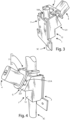
Figure 3 is a first view of the blocking system ofFigure 1 wherein said blocking system is assembled; -
Figure 4 is a second view of the blocking system ofFigure 1 wherein said blocking system is assembled; -
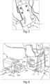
Figure 5 is a view of the blocking system applied on a portion of the steering column of the quad which shows the coupling element which rigidly couples said first element of the blocking system to a frame portion of the quad -
Figure 6 is a view of the blocking system applied on a portion of the steering column of the quad which shows the first element and the second element of the blocking system, wherein said first element is coupled to a frame portion of the quad and said second element is coupled to a portion of a handlebars of the quad, and the blocking device is ready to block said second element to said first element; -
Figure 7 is a partial view of the blocking system applied on a portion of the steering column, wherein the blocking device has a pin inserted into a first opening of the first element and into a second opening of the second element but does not block the second element to first element; -
Figure 8 is a partial view of the blocking system applied on a portion of the steering column, wherein the blocking device has a pin inserted into a first opening of the first element and into a second opening of the second element and blocks the second element to the first element; -
Figure 9 is a further partial view of the blocking system applied on a portion of the steering column, wherein the blocking device blocks the second element to the first element; -
Figure 10 is a partial view of the blocking system applied on a portion of the steering column, wherein the blocking device has been removed and the second element is slightly rotated with respect to the first element since said second element is no longer blocked to the first element through the blocking device; -
Figure 11 is a first exploded view of a second embodiment of the blocking system, according to the invention; -
Figure 12 is a second exploded view of the blocking system ofFigure 11 ; -
Figure 13 is a view of the blocking system ofFigure 11 wherein said blocking system is assembled; -
Figure 14 is a perspective view of a variant of the blocking device, wherein the body of the blocking device has a bell shape; -
Figure 15 is a perspective view from above of the blocking device shown inFigure 14 . - With reference to
Figures 1 to 10 , a first embodiment of a blocking system for blocking the steering column SC of a quad is described. - Said blocking system comprises:
- a
first element 1 shaped to surround a portion of said steering column SC, - a
second element 2 couplable to a portion of a handlebars S of said quad, - a
coupling element 3 for rigidly coupling saidfirst element 1 with a frame portion of said quad, so that saidfirst element 1 is blocked in position with respect to said frame portion, and - a
blocking device 4 for blocking saidsecond element 2 to saidfirst element 1. - With reference to the
first element 1 of the blocking system, saidblocking system 1 comprises amain body 10 which in turn comprises: - a
cavity 10A for receiving a portion of said steering column SC of said quad, - a
slot 100 extending along afirst surface 11 of saidmain body 10 to allow said portion of said steering column SC to be inserted saidcavity 10A, and - a
protrusion 121 protruding from asecond surface 12 of saidmain body 10, different from saidfirst surface 11, wherein saidprotrusion 121 is provided with afirst opening 121A. - With reference to the
main body 10, saidmain body 10 is substantially a hollow tubular body. - The
slot 100 is arranged on thefirst surface 11 of themain body 10 to allow the passage of a portion of the steering column SC inside saidmain body 10. - In other words, the
slot 100 extends along the entirefirst surface 11 of saidmain body 10, so as to divide saidfirst surface 11 into two parts: a first part and a second part spaced apart from each other. - A plurality of through
holes 11A is arranged on saidfirst surface 11. - Each through
hole 11A of said plurality of throughholes 11A allows the insertion of a respective security pin (not shown) to also be inserted into a respective throughhole 3A of thecoupling element 3 described in detail below. - In other words, the
first element 1 and thecoupling element 3 are coupled to each other through said security pins, each of which is inserted into a respective throughhole 3A of the third element as well as into a respective throughhole 11A of thefirst element 1. - In particular, each through
hole 11A is a threaded hole and each security pin comprises a threaded end portion to be screwed on said threaded hole. - It is preferably that each security pin further comprises a head detachable from said threaded end portion.
- In other words, after having inserted a security pin into the through
hole 3A of thecoupling element 3 and screwed said security pin on a respective throughhole 11A of thefirst element 1, it is possible to manually remove the head of said security pin, so as to prevent a criminal to easily decouple saidfirst element 1 from thecoupling element 3. - At least two through
holes 11A are arranged on thefirst surface 11 of themain body 10, in particular athrough hole 11A for each part of thefirst surface 11. - In the first embodiment that is described, four through
holes 11A are arranged on thefirst surface 11, two through holes for each part of thefirst surface 11. - In the first embodiment that is described, the
second surface 12 of themain body 10 is opposite to thefirst surface 11 mentioned above. - The first opening 121A serves to receive a
pin 400 of ablocking device 4 described in detail below. - As mentioned, the first opening 121A is formed in said
protrusion 121. - In the first embodiment that is described, the
protrusion 121 is a single piece with themain body 10. - However, it is not necessary that said
protrusion 121 is a single piece with saidmain body 10. - In the first embodiment that is described, the
first opening 121 is arranged on asurface 1211 of saidprotrusion 121 and saidsurface 1211 is arranged on a first plane forming a first angle (α) greater than 0° and less than 90° with a second plane on which saidsecond surface 12 is arranged. - In other words, the
surface 1211 of theprotrusion 121 on which thefirst opening 121A is formed is inclined with respect to thesecond surface 12 on which saidprotrusion 121 is arranged. - With reference to the
second element 2 of the blocking system, saidsecond element 2 comprises afirst portion 21 provided with asecond opening 21A. - Said
second opening 21A serves to receive apin 400 of theblocking device 4 mentioned above. - In other words, the
pin 400 of theblocking device 4 is to be inserted in thefirst opening 121A of thefirst element 1 and in thesecond opening 21A of thesecond element 2 in order to block thefirst element 1 and thesecond element 2 together. - Furthermore, the
first portion 21 of thesecond element 2 is provided with at least onefurther slot 21B for the insertion of arespective relief 41A of theblocking device 4 mentioned above. - In the first embodiment that is described, said
first portion 21 is provided with twofurther slots 21B, each of which allows the insertion of arespective relief 41A of theblocking device 4. - In particular, said two
further slots 21B are spaced apart from each other and saidsecond opening 21A is arranged on saidfirst portion 21 between said twofurther slots 21B. - Advantageously, each
further slot 21B on thesecond element 2 also serves as a guide for the correct positioning of theblocking device 4. - In the first embodiment that is described, the
first opening 121A of thefirst element 1 and thesecond opening 21A of thesecond element 2 have the same shape and size. - However, it is not necessary for said
first opening 121A and saidsecond opening 21A to have the same shape and size. - Furthermore, said
second element 2 comprises asecond portion 22 intended to contact a portion of the handlebars S. - In order to couple the
second element 2 to the portion of the handlebar S, saidsecond element 2 is provided with at least one throughhole 22A for the passage of a pin (not shown) comprising a threaded end portion. - This pin is one of the pins with which the quad is provided.
- A security nut comprising a threaded end portion is screwed on said pin to block the
second element 2 to said portion of said handlebars S. - It is preferable that the security nut has a head detachable from said threaded end portion.
- In this way, after having screwed said security nut on said pin, it is possible to manually remove the head of said security nut, so as to prevent a criminal from easily decoupling said
second element 2 from the handlebars S. - In the first embodiment that is described, in order to couple the
second element 2 to the portion of the handlebars S, saidsecond element 2 is provided with two throughholes 22A for the passage of a respective pin of the quad. - Furthermore, in the embodiment that is described, said
first portion 21 is inclined with respect to saidsecond portion 22. - When the blocking system is in use, said
first portion 21 is parallel or substantially parallel to thesurface 1211 of theprotrusion 121 of thefirst element 1, in such a way that thesecond opening 21A arranged on thefirst portion 21 of thesecond element 2 is parallel or substantially parallel to thefirst opening 121A of thefirst element 1. - In particular, said
first portion 21 forms a second angle β with saidsecond portion 22 greater than 90° and less than 180°. - With reference to the
coupling element 3, saidcoupling element 3 allows thefirst element 1 to be coupled to a frame portion of the quad, in such a way that thefirst element 1 is blocked in position with respect to said frame portion. - In the first embodiment that is described, said
coupling element 3 is a plate. - Said
coupling element 3 is provided with a plurality of throughholes 3A. - As already mentioned, the through
holes 3A of said plurality of throughholes 3A are arranged in such a way that, when the blocking system is in use, each throughhole 3A of said plurality of throughholes 3A is overlayed on a respective threaded throughhole 11A of thefirst surface 11 of thefirst element 1. - Said blocking system comprises a plurality of security pins to fix said
coupling element 3 to saidfirst element 1. - Each security pin is to be inserted into a respective pair of holes formed by a through
hole 3A arranged on thecoupling element 3 and by a threaded throughhole 11A arranged on thefirst surface 11 of thefirst element 1. - As already mentioned, each security pin preferably comprises a head detachable from a threaded end portion.
- Advantageously, after having inserted a respective security pin into a through
hole 3A of thecoupling element 3 and screwed said security pin on a threaded throughhole 11A of thefirst element 1, it is possible to manually remove the head of said security pin. - Said plurality of through
holes 3A comprises at least two throughholes 3A. - In the first embodiment that is described, said plurality of through
holes 3A comprises four throughholes 3A. - Said four through
holes 3A are arranged on thecoupling element 3 in such a way that each of said throughholes 3A of thecoupling element 3 is overlayed on a respective threaded throughhole 11A arranged on thefirst element 1, when saidcoupling element 3 is coupled to saidfirst element 1 and to said frame portion of the quad. - Furthermore, said
coupling element 3 is provided with at least one further throughhole 3B. - In order to couple the
coupling element 3 to a frame portion of the quad, saidcoupling element 3 is provided with said at least one further throughhole 3B for the passage of a further pin (not shown) comprising a threaded end portion . - Said further pin is one of the pins with which the quad is provided.
- A further security nut comprising a threaded end portion is screwed on said further pin to block said
coupling element 3 to said frame portion. - It is preferable that said further security nut ha a head detachable from said threaded end portion.
- In this way, after having screwed said further security nut on said further pin, it is possible to manually remove the head of said further security nut, so as to prevent a criminal from easily decoupling said
coupling element 3 from the frame of the quad. - In the first embodiment that is described, in order to couple the
coupling element 3 to a frame portion, saidcoupling element 3 is provided with two further throughholes 3B for the passage of a respective further pin of the quad. - With reference to the
blocking device 4, said blockingdevice 4 comprises: - a
body 40, - a
pin 400 extending outwards from anend surface 41 of saidbody 40 and is shaped to be inserted into saidfirst opening 121A of saidfirst element 1 and into saidsecond opening 21A of said second element, wherein saidpin 400 has a longitudinal axis A and comprises at least onefirst tooth 400A integral with saidpin 400, and is rotable around said longitudinal axis A with respect to saidbody 40 in such a way that saidfirst tooth 400A rotates between a first position, in which saidpin 400 is inserted into saidfirst opening 121A of saidfirst element 1 and into saidsecond opening 21A of saidsecond element 2 but saidfirst tooth 400A does not block saidsecond element 2 to saidfirst element 1, and a second position, in which saidpin 400 is inserted into saidfirst opening 121A of saidfirst element 1 and into saidsecond opening 21A of saidsecond element 2 and saidfirst tooth 400A blocks saidsecond element 2 to saidfirst element 1. - It is preferable that the rotation angle of said
pin 400 is equal to 90°. - Consequently, when the
pin 400 is in its second position it is rotated by a rotation angle equal to 90° with respect to its first position. - However, the rotation angle can have any value greater than 0° and less than 180°, without departing from the scope of the invention.
- In the first embodiment that is described, said
pin 400 comprises twofirst teeth 400A, i.e. a pair offirst teeth 400A. - The two
first teeth 400A of said pair offirst teeth 400A are aligned along an axis perpendicular or substantially perpendicular to the longitudinal axis A of thepin 400. - The
end surface 41 of thebody 40 of saidblocking device 4 is provided with at least onerelief 41A shaped to be inserted in saidfurther slot 21B arranged on thefirst portion 21 of thesecond element 2. - Since, as said above, in the first embodiment that is described, the
first portion 21 of thesecond element 2 is provided with twofurther slots 21B, theend surface 41 of theblocking device 4 is provided with tworeliefs 41A, spaced each other, each of which is shaped to be inserted into a respectivefurther slot 21B of thesecond element 2. - In particular, in the embodiment that is described, the
pin 400 comprises an end arranged on said end surface between said tworeliefs 41A. - Furthermore, the
pin 400 comprises at least onesecond tooth 400B, integral with saidpin 400, and saidsecond tooth 400B is arranged between saidend surface 41 and saidfirst tooth 400A. - When said blocking system is in use, said
second tooth 400B is arranged between saidprotrusion 121 of saidfirst element 1 and saidfirst portion 21 of saidsecond element 2. - In particular, said
second tooth 400B is sized in such a way as to contact saidprotrusion 121 of saidfirst element 1 and saidfirst portion 21 of saidsecond element 2. - In the first embodiment that is described, said
pin 400 comprises twosecond teeth 400B, i.e. a pair ofsecond teeth 400B. - The two
second teeth 400B of said pair ofsecond teeth 400B are aligned along a further axis perpendicular or substantially perpendicular to the longitudinal axis A of thepin 400. -
Figures 11 to 13 show a second embodiment of the blocking system. - In the second embodiment, the first element 1' and the second element 2' of the blocking system differ respectively from the
first element 1 and from thesecond element 2 described in the first embodiment of the blocking system. - With reference to the first element 1' of the blocking system shown in the second embodiment, similarly to the
first element 1 of the first embodiment described above, said first element 1' comprises a main body 10' which in turn comprises: - a
cavity 10A' for receiving a portion of said steering column SC of said quad, - a slot 100' extending along a first surface 11' of said main body 10' to allow said portion of said steering column SC to be inserted said
cavity 10A', and - a protrusion 121' protruding from a second surface 12' of said main body 10', different from said first surface 11', wherein said protrusion 121' is provided with a
first opening 121A'. - With reference to the main body 10', said main body 10' is substantially a hollow tubular body.
- The slot 100' arranged on the first surface 11' of the main body 10' allow the passage of a portion of the steering column SC inside said main body 10'.
- In other words, the slot 100' extends along the entire first surface 11' of said main body 10', so as to divide said first surface 11' into two parts: a first part and a second part spaced apart from each other.
- A plurality of through
holes 11A' is arranged on said first surface 11'. - Each through
hole 11A' of said plurality of throughholes 11A' allows the insertion of a respective security pin (not shown) to also be inserted into a respective throughhole 3A of thecoupling element 3 described in detail below. - In other words, the first element 1' and the
coupling element 3 are coupled to each other through said security pins, each of which is inserted into a respective throughhole 3A of the third element as well as into a respective throughhole 11A' of the first element 1'. - In particular, each through
hole 11A' is a threaded hole and each security pin comprises a threaded end portion to be screwed on said threaded hole. - It is preferably that each security pin further comprises a head detachable from said threaded end portion.
- In other words, after having inserted a security pin into the through
hole 3A of thecoupling element 3 and screwed said security pin on a respective throughhole 11A' of the first element 1', it is possible to manually remove the head of said security pin, so as to prevent a criminal to easily decouple saidfirst element 1 from thecoupling element 3. - At least two through
holes 11A' are arranged on the first surface 11' of the main body 10', in particular a throughhole 11A' for each part of the first surface 11'. - In the second embodiment that is described, four through
holes 11A' are arranged on the first surface 11', i.e. two through holes for each part of the first surface 11'. - In the second embodiment that is described, the second surface 12' of the main body 10' is opposite to the first surface 11' mentioned above.
- The
first opening 121A' serves to receive apin 400 of ablocking device 4 described in detail below. - As mentioned, the
first opening 121A' is formed in said protrusion 121'. - In the second embodiment that is described, the protrusion 121' is a single piece with the main body 10'.
- However, it is not necessary that said protrusion 121' is a single piece with said main body 10'.
- Differently from the first embodiment described above, in the second embodiment that is described, the
first opening 121A' is arranged on a surface 1211' of said protrusion 121' of the first element 1' and said surface 1211' is arranged on a first plane forming a first angle α' equal to 90° with a second angle on which said second surface 12' is arranged. - In other words, the surface 1211' of the protrusion 121' on which the
first opening 121A' is formed is not inclined with respect to the second surface 12' on which said protrusion 121' is arranged. - With reference to the second element 2' of the blocking system shown in the second embodiment, similarly to the
second element 2 of the blocking system of the first embodiment described above, said second element 2' comprises a first portion 21' provided with asecond opening 21A'. - Said
second opening 21A' serves to receive apin 400 of theblocking device 4 mentioned above. - In other words, the
pin 400 of theblocking device 4 is to be inserted into thefirst opening 121A' of the first element 1' and into thesecond opening 21A' of the second element 2' in order to block the first element 1' and the second element 2' together. - Furthermore, the first portion 21' of the second element 2' is provided with at least one
further slot 21B' for the insertion of arespective relief 41A of theblocking device 4 mentioned above. - In the second embodiment that is described, said first portion 21' is provided with two
further slots 21B', each of which allows the insertion of arespective relief 41A of theblocking device 4. - In particular, said two
further slots 21B' are spaced apart from each other and saidsecond opening 21A' is arranged on said first portion 21' between said twofurther slots 21B'. - Advantageously, each
further slot 21B' on the second element 2' also serves as a guide for the correct positioning of theblocking device 4. - In the second embodiment that is described, the
first opening 121A' of the first element 1' and thesecond opening 21A' of the second element 2' have the same shape and size. - However, it is not necessary that said
first opening 121A' and saidsecond opening 21A' have the same shape and size. - Furthermore, said second element 2' comprises a second portion 22' intended to contact the portion of the handlebars S.
- In order to couple the second element 2' to the portion of the handlebars S, said second element 2' is provided with at least one through
hole 22A' for the passage of a pin (not shown) comprising a threaded end portion. - Said pin is one of the pins with which the quad is provided.
- A security nut comprising a threaded end portion is screwed on said pin to block the second element 2' to said portion of said handlebars S.
- It is preferable that the security nut has a head detachable from said threaded end portion.
- In this way, after having screwed said security nut on said pin, it is possible to manually remove the head of said security nut, so as to prevent a criminal from easily decoupling said second element 2' from the handlebars S.
- In the second embodiment that is described, in order to couple the second element 2' to the portion of the handlebars S, said second element 2' is provided with two through
holes 22A' for the passage of a respective pin of the quad. - Differently from the first embodiment described above, in the second embodiment that is described, said first portion 21' and said second portion 22' are arranged on a same plane.
- When the blocking system is in use, said first portion 21' is parallel to the surface 1211' of the protrusion 121' of the first element 1', in such a way that the
second opening 21A' arranged on the first portion 21' of the second element 2' is parallel to thefirst opening 121A' of the first element 1'. -
Figures 14 and 15 show a variant of theblocking device 4. - In particular, the
body 40 of theblocking device 4 has a bell shape. - Advantageously, the bell shape of the
body 40 of the blocking device complicates tampering of theblocking device 4 itself by a criminal. - Advantageously, the blocking system, object of the invention, has a high level of security against a possible tampering, despite having a simple mechanical structure.
- A further advantage is given is given by the fact that the blocking system has a reduced bulk.
- The present invention has been described for illustrative, but not limitative purposes, according to its preferred embodiments, but it is to be understood that variations and/or modifications can be carried out by a skilled in the art, without departing from the scope thereof, as defined according to enclosed claims.
Claims (15)
- Blocking system for blocking a steering column (SC) of a quad, comprising:- a first element (1,1') shaped to surround a portion of said steering column (SC), wherein said first element (1,1') comprises a main body (10,10') comprising:a cavity (10A,10A') for receiving a portion of said steering column (SC) of said quad,a slot (100,100') extending along a first surface (11,11') of said main body (10,10') to allow said portion of said steering column (SC) to be inserted said cavity (10A, 10A'), anda protrusion (121,121') protruding from a second surface (12,12') of said main body (10,10'), different from said first surface (11,11'), wherein said protrusion (121,121') is provided with a first opening (121A,121A'),- a second element (2,2') couplable to a portion of a handlebars (S) of said quad, wherein said second element (2,2') comprises a first portion (21,21') provided with a second opening (21A,21A'),- a coupling element (3) for rigidly coupling said first element (1,1') with a frame portion of said quad, so that said first element (1,1') is blocked in position with respect to said frame portion,- a blocking device (4) for blocking said second element (2,2') to said first element (1,1'), wherein said blocking device (4) comprises:a pin (400) extending outwards from an end surface (41) of said body (40) and is shaped to be inserted into said first opening (121A, 121A') of said first element (1,1') and into said second opening (21A,21A') of said second element (2,2'), wherein said pin (400) has a longitudinal axis (A) and comprises at least one first tooth (400A) integral with said pin (400), and is rotable around said longitudinal axis (A) with respect to said body (40) in such a way that said first tooth (400A) rotates between a first position, in which said pin (400) is inserted into said first opening (121A,121A') of said first element (1,1') and into said second opening (21A,21A') of said second element (2,2') but said first tooth (400A) does not block said second element (2,2') to said first element (1,1'), and a second position, in which said pin (400) is inserted into said first opening (121A,121A') of said first element (1,1') and into said second opening (21A,21A') of said second element (2,2') and said first tooth (400A) blocks said second element (2,2') to said first element (1,1').
a body (40), - Blocking system according to claim 1, whereinsaid first portion (21,21') of said second element (2,2') is provided with at least one a further slot (21B,21B'), andwhereinthe end surface (41) of the body (40) of said blocking device (4) is provided with at least one relief (41A) shaped to be inserted in said further slot (21B,21 B').
- Blocking system according to claim 1, whereinsaid first portion (21,21') of said second element (2,2') is provided with two further slots (21B,21B') spaced each other and said second opening (21A,21A') is arranged on said first portion (21,21') between said two further slots (21B,21B'), andwhereinsaid end surface (41) of said body (40) of said blocking device (4) is provided with two reliefs (41A), spaced each other, each of which is shaped to be inserted in a respective further slot (21B,21B'); said pin (400) comprising an end arranged on said end surface (41) between said two reliefs (41A).
- Blocking system according to any one of the preceding claims, wherein said first opening (121A,121A') of said first element (1,1') and said second opening (21A,21A') of said second element (2,2') have the same shape and the same size.
- Blocking system according to any one of the preceding claims, whereinthe first surface (11,11') of the first element (1,1') is provided with a plurality of threaded through holes (11A), andsaid coupling element (3) is provided with a plurality of through holes (3A), wherein the through holes (3A) of said plurality of through holes (3A) are arranged in such a way that, when the blocking is in use, each through hole (3A) of said plurality of through holes (3A) of said coupling element (3) is overlayed on a respective threaded through hole (11A) of said first surface (11,11 ') of said first element (1,1'), andwhereinsaid blocking system comprises a plurality of security pins to fix said coupling element (3) to said first element (1,1'), wherein each security pin of said plurality of security pins comprises a threaded end portion and is to be inserted in a respective couple of holes formed by a through hole (3A) of said plurality of through holes (3A) of said coupling element (3) and a threaded through hole (11A) of the first (11,11') of said first element (1,1').
- Blocking system according to the preceding claim, wherein each security pin of said plurality of security pins comprises a head detachable from said threaded end portion.
- Blocking system according to any one of the preceding claims, whereinsaid second element (2,2') comprises a second portion (22,22') intended to contact a portion of the handlebars (S) and said second portion (22,22') is provided with at least one through hole (22A,22A') for the passage of a pin of said quad comprising a threaded end portion,whereinsaid blocking system comprises a respective security nut for each through hole (22A,22A') of the second element (2,2'), for fixing said second element (2,2') to the portion of the handlebars (S), wherein each security nut comprises a threaded end portion to be screwed on said pin of said quad.
- Blocking system according to the preceding claim, wherein each security nut comprises a head detachable from said threaded end portion.
- Blocking system according to claim 5 or 6, whereinsaid coupling element (3) is provided with two further through holes (3B), wherein said further through holes (3B) are arranged in such a way that, when the blocking system is in use, each further through hole (3B) is overlayed a respective hole arranged on said frame portion, so that a respective pin of the quad pass through a hole on said frame portion and a further through hole (3B), said pin of said quad comprising a threaded end portion,whereinsaid blocking system comprises a respective further security nut for each further through hole (3B), for fixing said coupling element (3) to said frame portion of said quad, wherein each further security nut comprises a threaded end portion to be screwed on said pin of said quad.
- Blocking system according to the preceding claim according to the preceding claim, wherein each further security nut comprises a head detachable from said threaded end portion.
- Blocking system according to any one of the claims 1-10, wherein
said first opening (121A) is arranged on a surface (1211) of said protrusion (121) of said first element (1) and said surface (1211) is arranged on a first plane forming a first angle (α) greater than 0° and less than 90° with a second plane on which said second surface (12) is arranged. - Blocking system according to any one the claims 1-10, wherein
said first opening (121A') is arranged on a surface (1211') of said protrusion (121') of said first element (1') and said surface (1211') is arranged on a first plane forming a first angle (α') equal to 90° with a second plane on which said second surface (12') is arranged. - Blocking system according to any one of the preceding claims, whereinthe pin (400) of said blocking device (4) comprises at least one second tooth (400B) integral with said pin (400), wherein said second tooth (400B) is arranged between said end surface (41) of the body (40) of the blocking device (4) and said first tooth (400A), andwhereinwhen said blocking system is in use, said second tooth (400B) is arranged between said protrusion (121,121') of said first element (1,1') and said first portion (21,21') of said second element (2,2').
- Blocking system according to the preceding claim, wherein said second tooth (400B) is dimensioned in such a way as to contact said protrusion (121,121') of said first element (1,1') and said first portion (21,21') of said second element (2,2').
- Blocking system according to any one of the preceding claims, wherein the body (40) of said blocking device (4) has a bell shape.
Applications Claiming Priority (1)
| Application Number | Priority Date | Filing Date | Title |
|---|---|---|---|
| IT102023000015963A IT202300015963A1 (en) | 2023-07-28 | 2023-07-28 | LOCKING SYSTEM TO LOCK THE STEERING COLUMN OF A QUAD |
Publications (3)
| Publication Number | Publication Date |
|---|---|
| EP4497666A1 true EP4497666A1 (en) | 2025-01-29 |
| EP4497666C0 EP4497666C0 (en) | 2026-03-18 |
| EP4497666B1 EP4497666B1 (en) | 2026-03-18 |
Family
ID=88291313
Family Applications (1)
| Application Number | Title | Priority Date | Filing Date |
|---|---|---|---|
| EP24190785.6A Active EP4497666B1 (en) | 2023-07-28 | 2024-07-25 | Blocking system for blocking the steering column of a quad |
Country Status (2)
| Country | Link |
|---|---|
| EP (1) | EP4497666B1 (en) |
| IT (1) | IT202300015963A1 (en) |
Citations (5)
| Publication number | Priority date | Publication date | Assignee | Title |
|---|---|---|---|---|
| JPH0364189U (en) * | 1989-10-27 | 1991-06-21 | ||
| EP1857335B1 (en) * | 2006-05-17 | 2010-08-11 | Kwang Yang Motor Co., Ltd. | Steering lock mechanism for all-terrain vehicle |
| WO2014040579A1 (en) * | 2012-09-17 | 2014-03-20 | Huf Hülsbeck & Fürst Gmbh & Co. Kg | Electric steering lock |
| CN206954352U (en) * | 2017-05-25 | 2018-02-02 | 浙江飞神车业有限公司 | All-terrain vehicle theft-prevention structure |
| CN210912689U (en) * | 2019-06-14 | 2020-07-03 | 赛格威科技有限公司 | Vehicle and integral vehicle lock thereof |
-
2023
- 2023-07-28 IT IT102023000015963A patent/IT202300015963A1/en unknown
-
2024
- 2024-07-25 EP EP24190785.6A patent/EP4497666B1/en active Active
Patent Citations (5)
| Publication number | Priority date | Publication date | Assignee | Title |
|---|---|---|---|---|
| JPH0364189U (en) * | 1989-10-27 | 1991-06-21 | ||
| EP1857335B1 (en) * | 2006-05-17 | 2010-08-11 | Kwang Yang Motor Co., Ltd. | Steering lock mechanism for all-terrain vehicle |
| WO2014040579A1 (en) * | 2012-09-17 | 2014-03-20 | Huf Hülsbeck & Fürst Gmbh & Co. Kg | Electric steering lock |
| CN206954352U (en) * | 2017-05-25 | 2018-02-02 | 浙江飞神车业有限公司 | All-terrain vehicle theft-prevention structure |
| CN210912689U (en) * | 2019-06-14 | 2020-07-03 | 赛格威科技有限公司 | Vehicle and integral vehicle lock thereof |
Also Published As
| Publication number | Publication date |
|---|---|
| EP4497666C0 (en) | 2026-03-18 |
| IT202300015963A1 (en) | 2025-01-28 |
| EP4497666B1 (en) | 2026-03-18 |
Similar Documents
| Publication | Publication Date | Title |
|---|---|---|
| ES2235117T3 (en) | DEVICE FOR BLOCKING THE STEERING SPINDLE OF A MOTOR VEHICLE. | |
| US20030005554A1 (en) | Clamp for wire harness | |
| EP4497666A1 (en) | Blocking system for blocking the steering column of a quad | |
| JPH08195161A (en) | Fuse connection structure | |
| CN115397725B (en) | Pedal for bicycle | |
| US20030038529A1 (en) | Fixing holder for a wheel cover | |
| LT4863B (en) | Dead-end clamp for an isulated overhead cable, especially a bundle-assembled overhead cable | |
| ES2491667T3 (en) | Cable plug assembly | |
| TWI650472B (en) | Cylinder lock | |
| ES2262935T3 (en) | DEVICE FOR MOUNTING THE SUPPORT BAR OF A BICYCLE HANDLEBAR ON THE STEERING TUBE. | |
| EP0709925B1 (en) | Improved receptacle housing for connector assembly | |
| JP3717248B2 (en) | Medical composition unit | |
| JP5030225B2 (en) | Electrical junction box | |
| EP0008308A1 (en) | Security interconnection device | |
| US5662486A (en) | Rotary connector | |
| JP2011006959A (en) | Handrail fitting, handrail device, and method for attaching the handrail device | |
| EP0987173A2 (en) | Device for the rapid engagement and disengagement of the stays for a bicycle mudguard | |
| EP1091058B1 (en) | Cylinder lock body | |
| CN107448454A (en) | For connecting the connector of the railing in bus | |
| JP3915214B2 (en) | Game machine | |
| KR100595366B1 (en) | Neutral pin release prevention structure of steering roll connector | |
| US9909343B2 (en) | Adaptable lock mounting device | |
| KR200370234Y1 (en) | Structure for preventing that neutral position pin come out from steering roll connector | |
| KR950007703Y1 (en) | Wheel Balancer of Wheel Balancer | |
| US20250167486A1 (en) | Connector, connector assembly and connector separation method |
Legal Events
| Date | Code | Title | Description |
|---|---|---|---|
| PUAI | Public reference made under article 153(3) epc to a published international application that has entered the european phase |
Free format text: ORIGINAL CODE: 0009012 |
|
| STAA | Information on the status of an ep patent application or granted ep patent |
Free format text: STATUS: THE APPLICATION HAS BEEN PUBLISHED |
|
| AK | Designated contracting states |
Kind code of ref document: A1 Designated state(s): AL AT BE BG CH CY CZ DE DK EE ES FI FR GB GR HR HU IE IS IT LI LT LU LV MC ME MK MT NL NO PL PT RO RS SE SI SK SM TR |
|
| STAA | Information on the status of an ep patent application or granted ep patent |
Free format text: STATUS: REQUEST FOR EXAMINATION WAS MADE |
|
| 17P | Request for examination filed |
Effective date: 20250716 |
|
| RIC1 | Information provided on ipc code assigned before grant |
Ipc: B62H 5/04 20060101AFI20250926BHEP Ipc: B62K 5/01 20130101ALI20250926BHEP Ipc: B62K 5/08 20060101ALI20250926BHEP |
|
| GRAP | Despatch of communication of intention to grant a patent |
Free format text: ORIGINAL CODE: EPIDOSNIGR1 |
|
| STAA | Information on the status of an ep patent application or granted ep patent |
Free format text: STATUS: GRANT OF PATENT IS INTENDED |
|
| INTG | Intention to grant announced |
Effective date: 20251106 |
|
| GRAS | Grant fee paid |
Free format text: ORIGINAL CODE: EPIDOSNIGR3 |
|
| GRAA | (expected) grant |
Free format text: ORIGINAL CODE: 0009210 |
|
| STAA | Information on the status of an ep patent application or granted ep patent |
Free format text: STATUS: THE PATENT HAS BEEN GRANTED |
|
| AK | Designated contracting states |
Kind code of ref document: B1 Designated state(s): AL AT BE BG CH CY CZ DE DK EE ES FI FR GB GR HR HU IE IS IT LI LT LU LV MC ME MK MT NL NO PL PT RO RS SE SI SK SM TR |
|
| REG | Reference to a national code |
Ref country code: CH Ref legal event code: F10 Free format text: ST27 STATUS EVENT CODE: U-0-0-F10-F00 (AS PROVIDED BY THE NATIONAL OFFICE) Effective date: 20260318 Ref country code: GB Ref legal event code: FG4D |
|
| REG | Reference to a national code |
Ref country code: IE Ref legal event code: FG4D |
|
| REG | Reference to a national code |
Ref country code: DE Ref legal event code: R096 Ref document number: 602024003262 Country of ref document: DE |
|
| U01 | Request for unitary effect filed |
Effective date: 20260318 |
|
| REG | Reference to a national code |
Ref country code: CH Ref legal event code: R17 Free format text: ST27 STATUS EVENT CODE: U-0-0-R10-R17 (AS PROVIDED BY THE NATIONAL OFFICE) Effective date: 20260427 |
|
| U07 | Unitary effect registered |
Designated state(s): AT BE BG DE DK EE FI FR IT LT LU LV MT NL PT RO SE SI Effective date: 20260326 |