EP4497606A1 - Printing method and robot system - Google Patents
Printing method and robot system Download PDFInfo
- Publication number
- EP4497606A1 EP4497606A1 EP24189680.2A EP24189680A EP4497606A1 EP 4497606 A1 EP4497606 A1 EP 4497606A1 EP 24189680 A EP24189680 A EP 24189680A EP 4497606 A1 EP4497606 A1 EP 4497606A1
- Authority
- EP
- European Patent Office
- Prior art keywords
- print head
- printing
- target object
- robot
- trajectory
- Prior art date
- Legal status (The legal status is an assumption and is not a legal conclusion. Google has not performed a legal analysis and makes no representation as to the accuracy of the status listed.)
- Pending
Links
Images







Classifications
-
- B—PERFORMING OPERATIONS; TRANSPORTING
- B41—PRINTING; LINING MACHINES; TYPEWRITERS; STAMPS
- B41J—TYPEWRITERS; SELECTIVE PRINTING MECHANISMS, i.e. MECHANISMS PRINTING OTHERWISE THAN FROM A FORME; CORRECTION OF TYPOGRAPHICAL ERRORS
- B41J3/00—Typewriters or selective printing or marking mechanisms characterised by the purpose for which they are constructed
- B41J3/407—Typewriters or selective printing or marking mechanisms characterised by the purpose for which they are constructed for marking on special material
- B41J3/4073—Printing on three-dimensional objects not being in sheet or web form, e.g. spherical or cubic objects
-
- B—PERFORMING OPERATIONS; TRANSPORTING
- B25—HAND TOOLS; PORTABLE POWER-DRIVEN TOOLS; MANIPULATORS
- B25J—MANIPULATORS; CHAMBERS PROVIDED WITH MANIPULATION DEVICES
- B25J11/00—Manipulators not otherwise provided for
- B25J11/0075—Manipulators for painting or coating
-
- B—PERFORMING OPERATIONS; TRANSPORTING
- B25—HAND TOOLS; PORTABLE POWER-DRIVEN TOOLS; MANIPULATORS
- B25J—MANIPULATORS; CHAMBERS PROVIDED WITH MANIPULATION DEVICES
- B25J19/00—Accessories fitted to manipulators, e.g. for monitoring, for viewing; Safety devices combined with or specially adapted for use in connection with manipulators
- B25J19/02—Sensing devices
- B25J19/021—Optical sensing devices
-
- B—PERFORMING OPERATIONS; TRANSPORTING
- B41—PRINTING; LINING MACHINES; TYPEWRITERS; STAMPS
- B41J—TYPEWRITERS; SELECTIVE PRINTING MECHANISMS, i.e. MECHANISMS PRINTING OTHERWISE THAN FROM A FORME; CORRECTION OF TYPOGRAPHICAL ERRORS
- B41J11/00—Devices or arrangements of selective printing mechanisms, e.g. ink-jet printers or thermal printers, for supporting or handling copy material in sheet or web form
- B41J11/0095—Detecting means for copy material, e.g. for detecting or sensing presence of copy material or its leading or trailing end
Definitions
- the present disclosure relates to a printing method and a robot system.
- the printing system described in JP-A-2013-202781 performs printing on a target object by ejecting ink toward the target object while moving a robot provided with a print head mounted at the distal end thereof along a printing trajectory.
- the printing system includes a rotation angle sensor for detecting the actual position of the print head, and a piezo actuator that is disposed between the sensor and the print head and that is for correcting the position of the print head based on the actual position of the print head.
- the printing method of the present disclosure is A printing method using a robot, the robot having a robot main body provided with a robot arm, a print head arranged on the robot arm, and an optical sensor that is provided with an imaging element for imaging a target object and that has a constant relative positional relationship with the print head, the printing method being for performing a printing operation on the target object by relatively moving the target object and the print head along a printing trajectory, the printing method comprising:
- a robot system includes a robot main body including a robot arm;
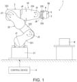
- FIG. 1 is an overall view of a robot system according to the first embodiment.
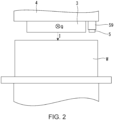
- FIG. 2 is a schematic view showing a printing operation.
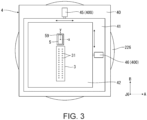
- FIG. 3 is a plan view showing a movement stage.
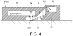
- FIG. 4 is a cross-sectional view of an optical sensor.
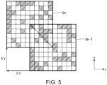
- FIG. 5 is a schematic diagram showing the detection principle of the optical sensor.
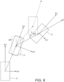
- FIG. 6 is a schematic view for explaining a method of detecting the position of the print head.
- FIG. 7 is a flowchart for explaining a printing method.
- FIG. 8 is a schematic diagram for explaining a problem of the optical sensor.
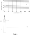
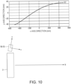
- FIGS. 9 and 10 are diagrams showing the relationship between translation amounts ⁇ x and ⁇ y.
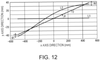
- FIGS. 11 and 12 are diagrams showing methods of measuring the inclination ⁇ .
- FIG. 13 is a block diagram showing a circuit for generating an error signal.
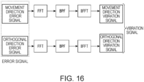
- FIGS. 14 to 16 are block diagrams showing circuits for generating a vibration signal.
- FIG. 17 is a flowchart for explaining
- the robot system 1 shown in FIG. 1 is applied to a printing system for performing a printing operation on a target object W.
- a robot system 1 has a robot 10.
- the robot 10 has a robot main body 2, a print head 3 as a tool mounted on the distal end of the robot main body 2, a movement stage 4 arranged between the robot main body 2 and the print head 3, an optical sensor 5 arranged on the print head 3, and a control device 9 for controlling the drive of the robot 10.
- the robot main body 2 is a six axes vertical articulated robot with six drive shafts, and includes a base 21 fixed to a mounting table, floor, or the like, and a robot arm 22 pivotably connected to the base 21.
- the robot arm 22 has a configuration in which six arms 221, 222, 223, 224, 225, and 226 are pivotably connected in this order from the base 21 side, and is provided with six joints J1, J2, J3, J4, J5, and J6.
- joints J1 to J6, joints J2, J3, and J5 are bending joints, and joints J1, J4, and J6 are twisting joints.
- Each of the joints J1, J2, J3, J4, J5, and J6 is equipped with a drive mechanism, which includes a motor as the drive source and an encoder for detecting the amount of rotation of the joint.
- the configuration of the robot main body 2 is not particularly limited.
- the number of arms provided in the robot arm 22 is not limited to six.
- the robot main body 2 may be a double arm robot, a horizontal articulated robot (scalar robot), or the like.
- the robot main body 2 may not be fixed to a mounting table, a floor, or the like, and may be capable of self-propulsion.
- the print head 3 is disposed at the distal end of the robot arm 22, that is, on the arm 226.
- the print head 3 is not particularly limited, but an ink jet head is used in this embodiment.
- the ink jet head has ink chambers (not shown), vibration plates arranged on a wall surface of the ink chambers (not shown), and ink ejection holes 31 connected to the ink chambers. Ink I in the ink chambers is ejected from the ink ejection holes 31 by vibrating the vibration plates. Also, as shown in FIG.
- printing is performed by ejecting ink I from the print head 3 while driving the robot arm 22 to move the print head 3 in a predetermined printing trajectory Q with respect to the target object W, so that the ink I adheres to the surface to be printed of the target object W.
- the movement stage 4 is disposed between the arm 226 and the print head 3, and is used to correct the position of the print head 3.
- the movement stage 4 includes a base 40 supported by the arm 226, a first stage 41 linearly movable with respect to the base 40 in a first direction A, and a second stage 42 linearly movable with respect to the first stage 41 in a second direction B, which is perpendicular to the first direction A.
- the print head 3 is disposed on the second stage 42.
- the movement stage 4 has a first stage drive section 45 for moving the first stage 41 with respect to the base 40 along the first direction A, and a second stage drive section 46 for moving the second stage 42 with respect to the first stage 41 along the second direction B.
- Each of the first and second stage drive sections 45 and 46 is provided with a piezoelectric actuator 400 driven by using the expansion and contraction of piezoelectric elements due to energization, and the vibration of the piezoelectric actuator 400 is transmitted to the first and second stages 41 and 42 to move them.
- a piezoelectric actuator 400 driven by using the expansion and contraction of piezoelectric elements due to energization, and the vibration of the piezoelectric actuator 400 is transmitted to the first and second stages 41 and 42 to move them.
- the piezoelectric actuator 400 it is possible to minutely and highly accurately control the movement amount and the movement speed of the first and second stages 41 and 42, and it is also possible to quickly switch the movement direction. Therefore, it is possible to accurately correct the position of the print head 3. It is also possible to reduce the size and weight of movement stage 4.
- the configuration of the movement stage 4 is not particularly limited.
- the first and second stage drive sections 45 and 46 may be configured to use a driving source other than the piezoelectric actuator 400, such as a motor that rotates by energization.
- the movement stage 4 may be omitted. In this case, the position of the print head 3 may be corrected by the robot arm 22.
- the optical sensor 5 is arranged on the second stage 42 of the movement stage 4 together with the print head 3 described above. Therefore, the relative positional relationship between the print head 3 and the optical sensor 5 is kept constant. Also, the position of the print head 3 is detected based on the output of the optical sensor 5.
- the optical sensor 5 is an optical tracking sensor 50 which is widely applied in optical mouses.
- the optical tracking sensor 50 has two detection axes, that is, the x-axis and the y-axis, which are orthogonal to each other, and can independently detect the translation amount ⁇ x in the x-axis direction and the translation amount ⁇ y in the x-and y-axis directions.
- the optical tracking sensor 50 has a rectangular shape extending along the y-axis in plan view.
- the shape of the optical tracking sensor 50 is not particularly limited, and may be a rectangular shape elongated along the x-axis, a square shape, a circular shape, or the like.
- the optical tracking sensor 50 includes a base 51, a pair of lens members 521 and 522, a light source 53, an imaging element 54, and a processing device 55.
- the base 51 is arranged to face the target object W.
- the light L emitted from the light source 53 is guided to the surface of the target object W by the lens member 521 and reflecting surfaces formed on inner surfaces of the base 51, is reflected by the surface of the target object W, is condensed by the lens member 522, and is received by the imaging element 54.
- the imaging element 54 continues imaging at a cycle of about 1 ms, and the processing device 55 obtains the translation amount of the optical tracking sensor 50 with respect to the target object W based on the image acquired by the imaging element 54.
- the processing device 55 compares the image Gn newly captured by the imaging element 54 with the image Gn-1 that was captured the previous time, and detects the movement amount of the image Gn with respect to the image Gn-1 by using an optical flow method or the like. That is, the movement amount of the image Gn with respect to the image Gn-1 is detected by comparing the brightness information of the image Gn and the image Gn-1. Also, based on the detection result, the processing device 55 detects translation amounts ⁇ x and ⁇ y of the optical tracking sensor 50 with respect to the target object W during the period from the time when the image Gn-1 was acquired to the time when the image Gn was acquired.
- the light source 53 is not particularly limited and, for example, an LED (light emitting diode), a laser light source, or the like can be used.
- the light L from the light source 53 is not particularly limited and, for example, red light, blue light, infrared light, or the like can be used.
- the imaging element 54 is not particularly limited, and for example, a CCD image sensor, a CMOS image sensor, or the like can be used.
- optical tracking sensor 50 has been described above. As can be seen from the fact that optical tracking sensors 50 are also widely applied to optical mouses, optical tracking sensors 50 are inexpensive, compact, and have high detection accuracy. Therefore, by using the optical tracking sensor 50 as the optical sensor 5, it is possible to obtain the robot system 1 capable of highly accurate position detection while achieving cost reduction and size reduction.
- the control device 9 controls the robot main body 2, the print head 3, the optical sensor 5, and the movement stage 4 independently or in conjunction with each other.
- the control device 9 is composed of, for example, a computer, and has a processor (CPU) for processing information, a memory communicably connected to the processor, and an external interface for connecting to external devices.
- Various programs executable by the processor are stored in the memory, and the processor can read and execute the programs stored in the memory.
- the control device 9 uses the optical tracking sensor 50 to detect the position of the print head 3 as follows. As described above, the relative positional relationship between the optical tracking sensor 50 and the print head 3 is constant. Therefore, as shown in FIG. 6 , the control device 9 sets the translation amount ⁇ x detected by the optical tracking sensor 50 as the movement amount ⁇ x3 of the print head 3 in the direction along the x-axis without changing it, and sets the translation amount ⁇ y as the movement amount ⁇ y3 of the print head 3 in the direction along the y-axis without changing it. Also, the control device 9 detects the position Pn of the print head 3 by adding the movement amounts ⁇ x3 and ⁇ y3 of the print head 3 that were detected this time to the previously detected position Pn1 of the print head 3.
- control device 9 repeats the processing described above to update the latest position of the print head 3.
- the control device 9 can also detect the trajectory of the print head 3 by connecting the repeatedly detected positions of the print head 3 in time series.
- the printing method has a pre-measurement step S1 and a printing step S2.
- the steps S1 and S2 will be described in detail below.
- the printing trajectory Q is constituted only by the translational motion of the print head 3 and does not substantially include the rotational motion of the print head 3.
- the optical tracking sensor 50 can detect only the translation amounts ⁇ x and ⁇ y with respect to the target object W, and cannot detect the rotation amount ⁇ with respect to the target object W. Therefore, when the printing trajectory Q includes rotational motion as shown in FIG. 8 , a deviation is generated between the position of the print head 3 detected based on the translation amounts ⁇ x and ⁇ y and the actual position of the print head 3 (hereinafter, also simply referred to as actual position).
- the print head 3 since the printing trajectory Q is set along the x-axis, the print head 3 does not move in the y-axis direction while moving along the printing trajectory Q as indicated by the solid line L1 in FIG. 9 .
- the x-axis may be inclined with respect to the printing trajectory Q due to, for example, mounting accuracy of the optical tracking sensor 50, a setting error of the printing trajectory Q, or the like. That is, the inclination of the x-axis with respect to the printing trajectory Q may deviate from the designed value.
- the optical tracking sensor 50 continues to move in the y-axis direction during movement along the printing trajectory Q.
- the translation amount ⁇ y continues to increase as indicated by the solid line L2 in the drawing, and accordingly, the position of the print head 3 detected from the translation amounts ⁇ x and ⁇ y is shifted from the actual position of the print head 3.
- Vibration generated in the print head 3 also causes the actual position of the print head 3 to deviate from the printing trajectory Q.
- the solid line L2 in FIG. 10 shows a state in which the positional deviation of the optical tracking sensor 50 and the vibration generated in the print head 3 are superimposed.
- the control device 9 measures the inclination of the x-axis with respect to the printing trajectory Q in advance before performing the printing operation.
- the control device 9 first moves the print head 3 along the printing trajectory Q under the same conditions as in the actual printing operation except that ink I is not ejected from the print head 3, and the control device 9 measures the trajectory of the print head 3 based on the translation amounts ⁇ x and ⁇ y output from the optical tracking sensor 50.
- the control device 9 approximates the measured trajectory to a linear function f1 as shown in FIG. 11 using the method of least squares, and stores the inclination of the approximated linear function f1 as the inclination ⁇ of the x-axis with respect to the printing trajectory Q.
- a linear function f2 is obtained in which a separation distance D1 in the y-axis direction at the start point of the printing trajectory Q and the separation distance D2 in the y-axis direction at the end point are equal to each other, and the inclination of the obtained linear function f2 is stored as an inclination ⁇ of the x-axis with respect to the printing trajectory Q.
- the method of calculating the inclination ⁇ is not particularly limited.
- the control device 9 uses the inclination ⁇ to correct the translation amounts ⁇ x and ⁇ y detected by the optical tracking sensor 50, and detects the actual position of the print head 3 based on the corrected values.
- the inclination of the x-axis with respect to the printing trajectory Q can be cancelled out, and the actual position of the print head 3 can be detected with high accuracy.
- the robot system 1 even if the target object W is not provided with a pattern for image recognition, the actual position of the print head 3 can be accurately detected.
- control device 9 compares the actual position of the print head 3 with the printing trajectory Q, that is, with the target value, and generates an error signal representing the amount that the actual position of the print head 3 deviates from the printing trajectory Q.
- Error signals include a movement direction error signal representing deviation in direction along the printing trajectory Q and an orthogonal direction error signal representing deviation in direction orthogonal to the printing trajectory Q.
- control device 9 extracts a vibration component from the error signal generated as described above, and generates a correction signal used for correcting the position of the print head 3.
- the control device 9 generates a vibration signal from which noise is removed by extracting a predetermined frequency component from the error signal.
- Vibration signals include a movement direction vibration signal obtained by extracting a predetermined frequency component from the moving direction error signal, and an orthogonal direction vibration signal obtained by extracting a predetermined frequency component from the orthogonal direction error signal.
- a frequency component of less than 3 Hz is defined as low-frequency noise
- a frequency component of 3 Hz or more and 50 Hz or less is defined as vibration component
- a frequency component of more than 50 Hz is defined as high-frequency noise.
- which frequency band is considered as noise and which frequency band is used as the vibration component is not particularly limited, and can be appropriately set according to the characteristics of the apparatus to be used.
- the method of generating the vibration signal from the error signal is not particularly limited, and for example, as shown in FIG. 14 , a method of passing the error signal through a low-pass filter LPF may be used.
- a low-pass filter LPF that passes frequency signals of less than 3 Hz is used, and the frequency signal that passed is removed from the error signal to obtain a vibration signal from which low-frequency noise has been removed.
- the error signal may be passed through a high-pass filter HPF.
- a high-pass filter HPF that passes frequency signals of 3Hz or more, a vibration signal in which low-frequency noise has been cut is obtained.
- FIG. 14 a method of passing the error signal through a low-pass filter LPF may be used.
- a low-pass filter LPF that passes frequency signals of less than 3 Hz is used, and the frequency signal that passed is removed from the error signal to obtain a vibration signal from which low-frequency noise has been removed.
- the error signal may be passed through a high-pass filter HPF.
- the error signal is expressed in the frequency domain by Fourier transform (FFT), the frequency component of 3 Hz or more and 50 Hz or less is extracted by a band-pass filter BPF, and finally, the vibration signal in which the low frequency noise and the high frequency noise have been cut is obtained by returning to the time domain expression by inverse Fourier transform (IFFT).
- FFT Fourier transform
- BPF band-pass filter
- the control device 9 generates an anti-phase signal of the vibration signal and uses this signal as a correction signal.
- the correction signal includes a movement direction correction signal, which is an anti-phase signal of the moving direction vibration signal, and an orthogonal direction correction signal, which is an anti-phase signal of the orthogonal direction vibration signal.
- the movement stage 4 is driven based on the correction signal to correct the position of the print head 3. That is, while the robot arm 22 is driven to move the print head 3 along the printing trajectory Q, the movement stage 4 is driven to cancel out the vibration of the print head 3.
- the deviation of the actual position of the print head 3 with respect to the printing trajectory Q can be suppressed to a small amount, and desirably the actual position of the print head 3 can be made to coincide with the printing trajectory Q. Therefore, high-precision printing can be performed.
- the response to the correction signal is enhanced as compared with the case where the vibration of the print head 3 is canceled by driving the robot arm 22. Therefore, the vibration of the print head 3 can be more accurately cancelled, and printing can be performed with high accuracy.
- the movement stage 4 may be omitted, and the vibration of the print head 3 may be canceled by driving the robot arm 22.
- the printing method using the robot system 1 has been described above, the printing method is not particularly limited.
- the correction signal is generated prior to the printing step S2 and, in the printing step S2, the position of the print head 3 is corrected using the correction signal that was generated in advance.
- the present disclosure is not limited to this, and the shift of the print head 3 with respect to the printing trajectory Q may be detected in real time during the printing step S2, and the movement stage 4 may be feedback controlled based on the detection result.
- the printing method has a pre-measurement step S1 and a printing step S2 as shown in FIG. 17 .
- the pre-measurement step S1 the inclination ⁇ is measured and stored.
- the control device 9 moves the print head 3 along the printing trajectory Q and, at a predetermined cycle during the movement, detects the actual position of the print head 3 based on the translation amounts ⁇ x and ⁇ y, which were detected by the optical tracking sensor 50, and on the inclination ⁇ . Further, the control device 9 generates a correction signal based on the deviation of the actual position with respect to the printing trajectory Q, and uses the generated correction signal to perform feedback control of the drive of the movement stage 4.
- the vibration of the print head 3 can be canceled out with high accuracy, and printing can be performed with high accuracy.
- the above-described methods can be used as appropriate, but the method shown in FIG. 16 cannot be used.
- this printing method uses the robot 10 having the robot main body 2 provided with the robot arm 22, the print head 3 arranged on the robot arm 22, and the optical sensor 5 that is provided with the imaging element 54 for imaging the target object W and that has a constant relative positional relationship with the print head 3, and is a printing method for performing a printing operation on the target object W by relatively moving the target object W and the print head 3 along the printing trajectory Q, wherein the print head 3 is moved along the printing trajectory Q, the actual position of the print head 3 is detected by comparing two images captured by the imaging element 54 at different imaging timings, and the position of the print head 3 is corrected based on the deviation of the actual position from the printing trajectory Q.
- the position of the print head 3 since the position of the print head 3 is detected on the basis of two images obtained by imaging the target object W, the position of the print head 3 can be detected with high accuracy even if no image recognition pattern is provided on the target object W.
- By correcting the position of the print head 3 based on the detection result it is also possible to suppress the deviation of the print head 3 with respect to the printing trajectory Q. Therefore, high-precision printing can be performed.
- the optical sensor 5 is the optical tracking sensor 50, is provided with the light source 53, the lens member 521 for irradiating the target object W with the light L from the light source 53, and the imaging element 54 for receiving the light L reflected by the target object W, and the optical sensor 5 detects the position of the print head 3 by comparing brightness information of two images. According to such a configuration, the position of the print head 3 can be accurately detected.
- the optical sensor 5 irradiates the target object W with the light L from the oblique direction.
- light and dark corresponding to minute unevenness in the surface of the target object W are likely to appear in the image picked up by the imaging element 54, and the position of the print head 3 can be accurately detected.
- the printing trajectory Q is constituted by the translational motion of the print head 3.
- the robot 10 is disposed between the robot arm 22 and the print head 3, has the movement stage 4 for displacing the print head 3, and corrects the position of the print head 3 by driving the movement stage 4.
- the response is enhanced as compared with the case where the position of the print head 3 is corrected by driving the robot arm 22, and the position of the print head 3 can be corrected more accurately.
- the robot system 1 has the robot main body 2 provided with the robot arm 22, the print head 3 that is arranged on the robot arm 22 and that serves as a tool for performing an operation on the target object W, the optical sensor 5 that is provided with the imaging element 54 for imaging the target object W and that has a constant relative positional relationship with the print head 3, and the control device 9 that relatively moves the target object W and the print head 3 along the printing trajectory Q, which is an operation trajectory, that detects the actual position of the print head 3 by comparing two images captured by the imaging element 54 at different imaging timings, and that corrects the position of the print head 3 based on the deviation of the actual position from the printing trajectory Q.
- the position of the print head 3 can be detected based on two images that were taken of the target object W. Therefore, it is possible to accurately detect the position of the print head 3.
- the tool is the print head 3 and the operation is printing. By this, it is possible to perform the printing operation with high accuracy.
- FIG. 18 is an overall view of a robot system according to a second embodiment.
- FIG. 19 to FIG. 21 are schematic diagrams showing how the printing operation is performed.
- the robot system 1 according to the present embodiment is the same as the robot system 1 of the first embodiment except that the robot 10 has the force sensor 7. It should be noted that, in the following description, the differences between the robot system 1 of the present embodiment and the first embodiment will be mainly described, and the description of the same matters will be omitted. In the figures of this embodiment, the same reference numerals are given to the same components as those of the above-described embodiment.
- the optical tracking sensor 50 is provided so as to protrude further toward the target object W than does the print head 3.
- a force sensor 7 is disposed between the robot main body 2 and the movement stage 4.
- the force sensor 7 has three detection axes orthogonal to each other, and can independently detect a translational force (axial force) along each detection axis and a rotational force (torque) about each detection axis. In such a robot system 1, the force sensor 7 is used to detect contact between the optical tracking sensor 50 and the target object W.
- the print head 3 can be moved along the printing trajectory Q while the optical tracking sensor 50 lightly contacts the target object W with a predetermined force.
- the separation distance between the optical tracking sensor 50 and the target object W can be kept constant. Therefore, detection error of the optical tracking sensor 50 caused by the variation in the separation distance between the optical tracking sensor 50 and the target object W is reduced, and the translation amounts ⁇ x and ⁇ y can be detected with higher accuracy. Since the separation distance between the print head 3 and the target object W can be kept constant, printing can be performed with higher accuracy.
- the disclosure is not limited to this and, for example, a contact section 6 as shown in FIG. 20 for abutment with the target object W may be separately arranged, and the contact section 6 may be brought into contact with the target object W. Also, for example, by performing printing while bringing the contact section 6 into contact with a position that does not overlap with the printing area of the target object W or with an area of the printing area that has not been printed on yet, it is possible to suppress contact with the ink I that has not dried completely. Therefore, printing can be performed with higher accuracy. It should be noted that, in the illustrated example, the contact section 6 protrudes from the holding member 59, the configuration of the contact section 6 is not particularly limited.
- the optical tracking sensor 50 When contact between the optical tracking sensor 50 and the target object W is detected by the force sensor 7, the optical tracking sensor 50 is controlled to be slightly separated from the target object W so that the optical tracking sensor 50 and the target object W are not in contact with each other so that, as shown in FIG. 21 , the print head 3 can be moved so as to trace close to the surface of the target object W.
- the separation distance between the print head 3 and the target object W can be made smaller and also the variation of the separation distance can be suppressed, so that printing can be performed with higher accuracy.
- the robot 10 has the force sensor 7 for detecting contact with the target object W, and the position of the print head 3 is corrected based on the detection result of the force sensor 7.
- the present disclosure is not limited to this, and the configurations and steps of the respective parts can be replaced with arbitrary configurations and steps having similar functions.
- processes such as conveyor tracking, adhesive application, polishing, and welding can be substituted, and any tool can be used in place of the print head.
- Other optional components and steps may be added to the present disclosure.
- the embodiments may be appropriately combined.
Landscapes
- Engineering & Computer Science (AREA)
- Robotics (AREA)
- Mechanical Engineering (AREA)
- Manufacturing & Machinery (AREA)
- Manipulator (AREA)
Abstract
A printing method using a robot, the robot having a robot main body provided with a robot arm, a print head arranged on the robot arm, and an optical sensor that is provided with an imaging element for imaging a target object and that has a constant relative positional relationship with the print head, the printing method being for performing a printing operation on the target object by relatively moving the target object and the print head along a printing trajectory, the printing method comprising: detecting the actual position of the print head by moving the print head along the printing trajectory and comparing two images captured by the imaging element at different imaging timings and correcting a position of the print head based on a deviation of the actual position from the printing trajectory.
Description
- The present application is based on, and claims priority from
JP Application Serial Number 2023-122294, filed July 27, 2023 - The present disclosure relates to a printing method and a robot system.
- The printing system described in
JP-A-2013-202781 - However, in the
JP-A-2013-202781 - The printing method of the present disclosure is A printing method using a robot, the robot having a robot main body provided with a robot arm, a print head arranged on the robot arm, and an optical sensor that is provided with an imaging element for imaging a target object and that has a constant relative positional relationship with the print head,
the printing method being for performing a printing operation on the target object by relatively moving the target object and the print head along a printing trajectory, the printing method comprising: - detecting the actual position of the print head by moving the print head along the printing trajectory and comparing two images captured by the imaging element at different imaging timings and
- correcting a position of the print head based on a deviation of the actual position from the printing trajectory.
- A robot system according to the present disclosure includes a robot main body including a robot arm;
- a tool disposed on the robot arm for performing an operation on a target object;
- an optical sensor that includes an imaging element for capturing an image of the target object and that has a constant relative positional relationship with the tool; and
- a control device configured to relatively move the target object and the tool along an operation trajectory, detect an actual position of the tool by comparing two images captured by the imaging element at different imaging timings, and correct the position of the tool based on a deviation of the actual position from the operation trajectory.
-
-
FIG. 1 is an overall view of a robot system according to the first embodiment. -
FIG. 2 is a schematic view showing a printing operation. -
FIG. 3 is a plan view showing a movement stage. -
FIG. 4 is a cross-sectional view of an optical sensor. -
FIG. 5 is a schematic diagram showing the detection principle of the optical sensor. -
FIG. 6 is a schematic view for explaining a method of detecting the position of the print head. -
FIG. 7 is a flowchart for explaining a printing method. -
FIG. 8 is a schematic diagram for explaining a problem of the optical sensor. -
FIG. 9 is a diagram showing the relationship between the translation amounts Δx and Δy. -
FIG. 10 is a diagram showing the relationship between the translation amounts Δx and Δy. -
FIG. 11 is a diagram showing a method of measuring inclination θ. -
FIG. 12 is a diagram showing a method of measuring the inclination θ. -
FIG. 13 is a block diagram showing a circuit for generating an error signal. -
FIG. 14 is a block diagram showing a circuit for generating a vibration signal. -
FIG. 15 is a block diagram showing a circuit for generating a vibration signal. -
FIG. 16 is a block diagram showing a circuit for generating a vibration signal. -
FIG. 17 is a flowchart for explaining a modification of the printing method. -
FIG. 18 is an overall view of a robot system according to a second embodiment. -
FIG. 19 is a schematic view showing a printing operation. -
FIG. 20 is a schematic view showing a printing operation. -
FIG. 21 is a schematic view showing a printing operation. - Hereinafter, a printing method and a robot system of the present disclosure will be described in detail based on embodiments shown in the accompanying drawings.
-
FIG. 1 is an overall view of a robot system according to the first embodiment.FIG. 2 is a schematic view showing a printing operation.FIG. 3 is a plan view showing a movement stage.FIG. 4 is a cross-sectional view of an optical sensor.FIG. 5 is a schematic diagram showing the detection principle of the optical sensor.FIG. 6 is a schematic view for explaining a method of detecting the position of the print head.FIG. 7 is a flowchart for explaining a printing method.FIG. 8 is a schematic diagram for explaining a problem of the optical sensor.FIGS. 9 and10 are diagrams showing the relationship between translation amounts Δx and Δy.FIGS. 11 and12 are diagrams showing methods of measuring the inclination θ.FIG. 13 is a block diagram showing a circuit for generating an error signal.FIGS. 14 to 16 are block diagrams showing circuits for generating a vibration signal.FIG. 17 is a flowchart for explaining a modification of the printing method. - The
robot system 1 shown inFIG. 1 is applied to a printing system for performing a printing operation on a target object W.A robot system 1 has arobot 10. Therobot 10 has a robotmain body 2, aprint head 3 as a tool mounted on the distal end of the robotmain body 2, amovement stage 4 arranged between the robotmain body 2 and theprint head 3, anoptical sensor 5 arranged on theprint head 3, and acontrol device 9 for controlling the drive of therobot 10. - The robot
main body 2 is a six axes vertical articulated robot with six drive shafts, and includes abase 21 fixed to a mounting table, floor, or the like, and arobot arm 22 pivotably connected to thebase 21. Therobot arm 22 has a configuration in which sixarms base 21 side, and is provided with six joints J1, J2, J3, J4, J5, and J6. Among the joints J1 to J6, joints J2, J3, and J5 are bending joints, and joints J1, J4, and J6 are twisting joints. Each of the joints J1, J2, J3, J4, J5, and J6 is equipped with a drive mechanism, which includes a motor as the drive source and an encoder for detecting the amount of rotation of the joint. - However, the configuration of the robot
main body 2 is not particularly limited. For example, the number of arms provided in therobot arm 22 is not limited to six. The robotmain body 2 may be a double arm robot, a horizontal articulated robot (scalar robot), or the like. The robotmain body 2 may not be fixed to a mounting table, a floor, or the like, and may be capable of self-propulsion. - The
print head 3 is disposed at the distal end of therobot arm 22, that is, on thearm 226. Theprint head 3 is not particularly limited, but an ink jet head is used in this embodiment. The ink jet head has ink chambers (not shown), vibration plates arranged on a wall surface of the ink chambers (not shown), and ink ejection holes 31 connected to the ink chambers. Ink I in the ink chambers is ejected from the ink ejection holes 31 by vibrating the vibration plates. Also, as shown inFIG. 2 , printing is performed by ejecting ink I from theprint head 3 while driving therobot arm 22 to move theprint head 3 in a predetermined printing trajectory Q with respect to the target object W, so that the ink I adheres to the surface to be printed of the target object W. - The
movement stage 4 is disposed between thearm 226 and theprint head 3, and is used to correct the position of theprint head 3. As shown inFIG. 3 , themovement stage 4 includes a base 40 supported by thearm 226, afirst stage 41 linearly movable with respect to the base 40 in a first direction A, and asecond stage 42 linearly movable with respect to thefirst stage 41 in a second direction B, which is perpendicular to the first direction A. Also, theprint head 3 is disposed on thesecond stage 42. - The
movement stage 4 has a firststage drive section 45 for moving thefirst stage 41 with respect to thebase 40 along the first direction A, and a secondstage drive section 46 for moving thesecond stage 42 with respect to thefirst stage 41 along the second direction B. - Each of the first and second
stage drive sections piezoelectric actuator 400 driven by using the expansion and contraction of piezoelectric elements due to energization, and the vibration of thepiezoelectric actuator 400 is transmitted to the first andsecond stages piezoelectric actuator 400, it is possible to minutely and highly accurately control the movement amount and the movement speed of the first andsecond stages print head 3. It is also possible to reduce the size and weight ofmovement stage 4. Therefore, it is possible to suppress as much as possible an increase in the weight of the distal end of the robotmain body 2 caused by the arrangement of themovement stage 4, and it is possible to effectively suppress a decrease in the drive characteristics such as the responsiveness and the damping property of the robotmain body 2. - However, the configuration of the
movement stage 4 is not particularly limited. For example, the first and secondstage drive sections piezoelectric actuator 400, such as a motor that rotates by energization. Themovement stage 4 may be omitted. In this case, the position of theprint head 3 may be corrected by therobot arm 22. - As shown in
FIG. 3 , theoptical sensor 5 is arranged on thesecond stage 42 of themovement stage 4 together with theprint head 3 described above. Therefore, the relative positional relationship between theprint head 3 and theoptical sensor 5 is kept constant. Also, the position of theprint head 3 is detected based on the output of theoptical sensor 5. - The
optical sensor 5 is anoptical tracking sensor 50 which is widely applied in optical mouses. Theoptical tracking sensor 50 has two detection axes, that is, the x-axis and the y-axis, which are orthogonal to each other, and can independently detect the translation amount Δx in the x-axis direction and the translation amount Δy in the x-and y-axis directions. Theoptical tracking sensor 50 has a rectangular shape extending along the y-axis in plan view. However, the shape of theoptical tracking sensor 50 is not particularly limited, and may be a rectangular shape elongated along the x-axis, a square shape, a circular shape, or the like. - As shown in
FIG. 4 , theoptical tracking sensor 50 includes abase 51, a pair oflens members light source 53, animaging element 54, and aprocessing device 55. Thebase 51 is arranged to face the target object W. The light L emitted from thelight source 53 is guided to the surface of the target object W by thelens member 521 and reflecting surfaces formed on inner surfaces of thebase 51, is reflected by the surface of the target object W, is condensed by thelens member 522, and is received by theimaging element 54. Theimaging element 54 continues imaging at a cycle of about 1 ms, and theprocessing device 55 obtains the translation amount of theoptical tracking sensor 50 with respect to the target object W based on the image acquired by theimaging element 54. - Specifically, as shown in
FIG. 5 , when the target object W is irradiated with light L, light and dark corresponding to minute unevenness in the surface of the target object W appear in the image captured by theimaging element 54. Then, theprocessing device 55 compares the image Gn newly captured by theimaging element 54 with the image Gn-1 that was captured the previous time, and detects the movement amount of the image Gn with respect to the image Gn-1 by using an optical flow method or the like. That is, the movement amount of the image Gn with respect to the image Gn-1 is detected by comparing the brightness information of the image Gn and the image Gn-1. Also, based on the detection result, theprocessing device 55 detects translation amounts Δx and Δy of theoptical tracking sensor 50 with respect to the target object W during the period from the time when the image Gn-1 was acquired to the time when the image Gn was acquired. - In particular, as in the present embodiment, by irradiating the light L in an oblique direction with respect to the target object W, that is, in a direction inclined with respect to the normal line of the surface to be printed on of the target object W, light and dark appear more clearly, and the translation amounts Δx and Δy can be detected more accurately.
- It should be noted that the
light source 53 is not particularly limited and, for example, an LED (light emitting diode), a laser light source, or the like can be used. The light L from thelight source 53 is not particularly limited and, for example, red light, blue light, infrared light, or the like can be used. Theimaging element 54 is not particularly limited, and for example, a CCD image sensor, a CMOS image sensor, or the like can be used. - The
optical tracking sensor 50 has been described above. As can be seen from the fact thatoptical tracking sensors 50 are also widely applied to optical mouses,optical tracking sensors 50 are inexpensive, compact, and have high detection accuracy. Therefore, by using theoptical tracking sensor 50 as theoptical sensor 5, it is possible to obtain therobot system 1 capable of highly accurate position detection while achieving cost reduction and size reduction. - The
control device 9 controls the robotmain body 2, theprint head 3, theoptical sensor 5, and themovement stage 4 independently or in conjunction with each other. Thecontrol device 9 is composed of, for example, a computer, and has a processor (CPU) for processing information, a memory communicably connected to the processor, and an external interface for connecting to external devices. Various programs executable by the processor are stored in the memory, and the processor can read and execute the programs stored in the memory. - The
control device 9 uses theoptical tracking sensor 50 to detect the position of theprint head 3 as follows. As described above, the relative positional relationship between theoptical tracking sensor 50 and theprint head 3 is constant. Therefore, as shown inFIG. 6 , thecontrol device 9 sets the translation amount Δx detected by theoptical tracking sensor 50 as the movement amount Δx3 of theprint head 3 in the direction along the x-axis without changing it, and sets the translation amount Δy as the movement amount Δy3 of theprint head 3 in the direction along the y-axis without changing it. Also, thecontrol device 9 detects the position Pn of theprint head 3 by adding the movement amounts Δx3 and Δy3 of theprint head 3 that were detected this time to the previously detected position Pn1 of theprint head 3. Each time theoptical tracking sensor 50 transmits new translation amounts Δx and Δy, thecontrol device 9 repeats the processing described above to update the latest position of theprint head 3. Thecontrol device 9 can also detect the trajectory of theprint head 3 by connecting the repeatedly detected positions of theprint head 3 in time series. - The configuration of the
robot system 1 has been described above. Next, a printing method of printing on the target object W using therobot system 1 will be described. As shown inFIG. 7 , the printing method has a pre-measurement step S1 and a printing step S2. The steps S1 and S2 will be described in detail below. - It should be noted that in the printing method using the
robot system 1, the printing trajectory Q is constituted only by the translational motion of theprint head 3 and does not substantially include the rotational motion of theprint head 3. As described above, theoptical tracking sensor 50 can detect only the translation amounts Δx and Δy with respect to the target object W, and cannot detect the rotation amount Δθ with respect to the target object W. Therefore, when the printing trajectory Q includes rotational motion as shown inFIG. 8 , a deviation is generated between the position of theprint head 3 detected based on the translation amounts Δx and Δy and the actual position of the print head 3 (hereinafter, also simply referred to as actual position). Therefore, by configuring the printing trajectory Q only by the translational motion of theprint head 3, it is possible to suppress the deviation between the position of theprint head 3 detected based on the translation amounts Δx and Δy and the actual position of theprint head 3. By this, even if an inexpensiveoptical tracking sensor 50 is used, the position of theprint head 3 can be detected with high accuracy, and printing can be performed with high accuracy. It should be noted that in the present embodiment, a case where the printing trajectory Q is set along the x-axis will be described. - In this embodiment, since the printing trajectory Q is set along the x-axis, the
print head 3 does not move in the y-axis direction while moving along the printing trajectory Q as indicated by the solid line L1 inFIG. 9 . However, as shown inFIG. 10 , the x-axis may be inclined with respect to the printing trajectory Q due to, for example, mounting accuracy of theoptical tracking sensor 50, a setting error of the printing trajectory Q, or the like. That is, the inclination of the x-axis with respect to the printing trajectory Q may deviate from the designed value. When the x-axis is tilted with respect to the printing trajectory Q, theoptical tracking sensor 50 continues to move in the y-axis direction during movement along the printing trajectory Q. Therefore, although movement is along the printing trajectory Q, the translation amount Δy continues to increase as indicated by the solid line L2 in the drawing, and accordingly, the position of theprint head 3 detected from the translation amounts Δx and Δy is shifted from the actual position of theprint head 3. - Vibration generated in the
print head 3 also causes the actual position of theprint head 3 to deviate from the printing trajectory Q. It should be noted that the solid line L2 inFIG. 10 shows a state in which the positional deviation of theoptical tracking sensor 50 and the vibration generated in theprint head 3 are superimposed. - Therefore, in the pre-measurement step S1, the
control device 9 measures the inclination of the x-axis with respect to the printing trajectory Q in advance before performing the printing operation. To be specific, thecontrol device 9 first moves theprint head 3 along the printing trajectory Q under the same conditions as in the actual printing operation except that ink I is not ejected from theprint head 3, and thecontrol device 9 measures the trajectory of theprint head 3 based on the translation amounts Δx and Δy output from theoptical tracking sensor 50. Next, thecontrol device 9 approximates the measured trajectory to a linear function f1 as shown inFIG. 11 using the method of least squares, and stores the inclination of the approximated linear function f1 as the inclination θ of the x-axis with respect to the printing trajectory Q. Alternatively, as shown inFIG. 12 , a linear function f2 is obtained in which a separation distance D1 in the y-axis direction at the start point of the printing trajectory Q and the separation distance D2 in the y-axis direction at the end point are equal to each other, and the inclination of the obtained linear function f2 is stored as an inclination θ of the x-axis with respect to the printing trajectory Q. However, the method of calculating the inclination θ is not particularly limited. - Also, as shown in
FIG. 13 , thecontrol device 9 uses the inclination θ to correct the translation amounts Δx and Δy detected by theoptical tracking sensor 50, and detects the actual position of theprint head 3 based on the corrected values. In this way, by correcting the translation amounts Δx and Δy using the inclination θ, the inclination of the x-axis with respect to the printing trajectory Q can be cancelled out, and the actual position of theprint head 3 can be detected with high accuracy. In this way, according to therobot system 1, even if the target object W is not provided with a pattern for image recognition, the actual position of theprint head 3 can be accurately detected. - Further, the
control device 9 compares the actual position of theprint head 3 with the printing trajectory Q, that is, with the target value, and generates an error signal representing the amount that the actual position of theprint head 3 deviates from the printing trajectory Q. Error signals include a movement direction error signal representing deviation in direction along the printing trajectory Q and an orthogonal direction error signal representing deviation in direction orthogonal to the printing trajectory Q. - Next, the
control device 9 extracts a vibration component from the error signal generated as described above, and generates a correction signal used for correcting the position of theprint head 3. - Specifically, first, the
control device 9 generates a vibration signal from which noise is removed by extracting a predetermined frequency component from the error signal. Vibration signals include a movement direction vibration signal obtained by extracting a predetermined frequency component from the moving direction error signal, and an orthogonal direction vibration signal obtained by extracting a predetermined frequency component from the orthogonal direction error signal. It should be noted that in this embodiment, a frequency component of less than 3 Hz is defined as low-frequency noise, a frequency component of 3 Hz or more and 50 Hz or less is defined as vibration component, and a frequency component of more than 50 Hz is defined as high-frequency noise. However, which frequency band is considered as noise and which frequency band is used as the vibration component is not particularly limited, and can be appropriately set according to the characteristics of the apparatus to be used. - The method of generating the vibration signal from the error signal is not particularly limited, and for example, as shown in
FIG. 14 , a method of passing the error signal through a low-pass filter LPF may be used. In this case, a low-pass filter LPF that passes frequency signals of less than 3 Hz is used, and the frequency signal that passed is removed from the error signal to obtain a vibration signal from which low-frequency noise has been removed. For example, as shown inFIG. 15 , the error signal may be passed through a high-pass filter HPF. In this case, by using a high-pass filter HPF that passes frequency signals of 3Hz or more, a vibration signal in which low-frequency noise has been cut is obtained. For example, as shown inFIG. 16 , the error signal is expressed in the frequency domain by Fourier transform (FFT), the frequency component of 3 Hz or more and 50 Hz or less is extracted by a band-pass filter BPF, and finally, the vibration signal in which the low frequency noise and the high frequency noise have been cut is obtained by returning to the time domain expression by inverse Fourier transform (IFFT). - Next, the
control device 9 generates an anti-phase signal of the vibration signal and uses this signal as a correction signal. The correction signal includes a movement direction correction signal, which is an anti-phase signal of the moving direction vibration signal, and an orthogonal direction correction signal, which is an anti-phase signal of the orthogonal direction vibration signal. - In the printing step S2, while the
robot arm 22 is driven to move theprint head 3 along the printing trajectory Q, themovement stage 4 is driven based on the correction signal to correct the position of theprint head 3. That is, while therobot arm 22 is driven to move theprint head 3 along the printing trajectory Q, themovement stage 4 is driven to cancel out the vibration of theprint head 3. - According to such a method, the deviation of the actual position of the
print head 3 with respect to the printing trajectory Q can be suppressed to a small amount, and desirably the actual position of theprint head 3 can be made to coincide with the printing trajectory Q. Therefore, high-precision printing can be performed. In particular, by canceling out the vibration of theprint head 3 by driving themovement stage 4, the response to the correction signal is enhanced as compared with the case where the vibration of theprint head 3 is canceled by driving therobot arm 22. Therefore, the vibration of theprint head 3 can be more accurately cancelled, and printing can be performed with high accuracy. However, themovement stage 4 may be omitted, and the vibration of theprint head 3 may be canceled by driving therobot arm 22. - Although the printing method using the
robot system 1 has been described above, the printing method is not particularly limited. For example, in the method described above, the correction signal is generated prior to the printing step S2 and, in the printing step S2, the position of theprint head 3 is corrected using the correction signal that was generated in advance. However, the present disclosure is not limited to this, and the shift of theprint head 3 with respect to the printing trajectory Q may be detected in real time during the printing step S2, and themovement stage 4 may be feedback controlled based on the detection result. - Even in such a case, the printing method has a pre-measurement step S1 and a printing step S2 as shown in
FIG. 17 . In the pre-measurement step S1, the inclination θ is measured and stored. In the printing step S2, thecontrol device 9 moves theprint head 3 along the printing trajectory Q and, at a predetermined cycle during the movement, detects the actual position of theprint head 3 based on the translation amounts Δx and Δy, which were detected by theoptical tracking sensor 50, and on the inclination θ. Further, thecontrol device 9 generates a correction signal based on the deviation of the actual position with respect to the printing trajectory Q, and uses the generated correction signal to perform feedback control of the drive of themovement stage 4. As described above, by detecting the deviation of theprint head 3 from the printing trajectory Q in real time and performing feedback control of themovement stage 4 so that the deviation becomes small, desirably zero, the vibration of theprint head 3 can be canceled out with high accuracy, and printing can be performed with high accuracy. It should be noted that, as a method of measuring the inclination θ and a method of generating the correction signal, the above-described methods can be used as appropriate, but the method shown inFIG. 16 cannot be used. - The
robot system 1 and the printing method using therobot system 1 have been described above. As described above, this printing method uses the robot 10 having the robot main body 2 provided with the robot arm 22, the print head 3 arranged on the robot arm 22, and the optical sensor 5 that is provided with the imaging element 54 for imaging the target object W and that has a constant relative positional relationship with the print head 3, and is a printing method for performing a printing operation on the target object W by relatively moving the target object W and the print head 3 along the printing trajectory Q, wherein the print head 3 is moved along the printing trajectory Q, the actual position of the print head 3 is detected by comparing two images captured by the imaging element 54 at different imaging timings, and the position of the print head 3 is corrected based on the deviation of the actual position from the printing trajectory Q. According to such a configuration, since the position of the print head 3 is detected on the basis of two images obtained by imaging the target object W, the position of the print head 3 can be detected with high accuracy even if no image recognition pattern is provided on the target object W. By correcting the position of the print head 3 based on the detection result, it is also possible to suppress the deviation of the print head 3 with respect to the printing trajectory Q. Therefore, high-precision printing can be performed. - As described above, the
optical sensor 5 is theoptical tracking sensor 50, is provided with thelight source 53, thelens member 521 for irradiating the target object W with the light L from thelight source 53, and theimaging element 54 for receiving the light L reflected by the target object W, and theoptical sensor 5 detects the position of theprint head 3 by comparing brightness information of two images. According to such a configuration, the position of theprint head 3 can be accurately detected. - As described above, the
optical sensor 5 irradiates the target object W with the light L from the oblique direction. By this, light and dark corresponding to minute unevenness in the surface of the target object W are likely to appear in the image picked up by theimaging element 54, and the position of theprint head 3 can be accurately detected. - As described above, the printing trajectory Q is constituted by the translational motion of the
print head 3. By this, even when theoptical sensor 5 can detect only the translational motion of theprint head 3, it is possible to accurately detect the position of theprint head 3. - As described above, the
robot 10 is disposed between therobot arm 22 and theprint head 3, has themovement stage 4 for displacing theprint head 3, and corrects the position of theprint head 3 by driving themovement stage 4. By this, the response is enhanced as compared with the case where the position of theprint head 3 is corrected by driving therobot arm 22, and the position of theprint head 3 can be corrected more accurately. - As described above, the
robot system 1 has the robotmain body 2 provided with therobot arm 22, theprint head 3 that is arranged on therobot arm 22 and that serves as a tool for performing an operation on the target object W, theoptical sensor 5 that is provided with theimaging element 54 for imaging the target object W and that has a constant relative positional relationship with theprint head 3, and thecontrol device 9 that relatively moves the target object W and theprint head 3 along the printing trajectory Q, which is an operation trajectory, that detects the actual position of theprint head 3 by comparing two images captured by theimaging element 54 at different imaging timings, and that corrects the position of theprint head 3 based on the deviation of the actual position from the printing trajectory Q. According to such a configuration, the position of theprint head 3 can be detected based on two images that were taken of the target object W. Therefore, it is possible to accurately detect the position of theprint head 3. - As described above, the tool is the
print head 3 and the operation is printing. By this, it is possible to perform the printing operation with high accuracy. -
FIG. 18 is an overall view of a robot system according to a second embodiment.FIG. 19 to FIG. 21 are schematic diagrams showing how the printing operation is performed. - The
robot system 1 according to the present embodiment is the same as therobot system 1 of the first embodiment except that therobot 10 has theforce sensor 7. It should be noted that, in the following description, the differences between therobot system 1 of the present embodiment and the first embodiment will be mainly described, and the description of the same matters will be omitted. In the figures of this embodiment, the same reference numerals are given to the same components as those of the above-described embodiment. - As shown in
FIG. 18 , in therobot system 1 of the present embodiment, theoptical tracking sensor 50 is provided so as to protrude further toward the target object W than does theprint head 3. Aforce sensor 7 is disposed between the robotmain body 2 and themovement stage 4. Theforce sensor 7 has three detection axes orthogonal to each other, and can independently detect a translational force (axial force) along each detection axis and a rotational force (torque) about each detection axis. In such arobot system 1, theforce sensor 7 is used to detect contact between theoptical tracking sensor 50 and the target object W. - According to such a configuration, by feed back of the detection result of the
force sensor 7, as shown inFIG. 19 , theprint head 3 can be moved along the printing trajectory Q while theoptical tracking sensor 50 lightly contacts the target object W with a predetermined force. According to this method, the separation distance between theoptical tracking sensor 50 and the target object W can be kept constant. Therefore, detection error of theoptical tracking sensor 50 caused by the variation in the separation distance between theoptical tracking sensor 50 and the target object W is reduced, and the translation amounts Δx and Δy can be detected with higher accuracy. Since the separation distance between theprint head 3 and the target object W can be kept constant, printing can be performed with higher accuracy. - Although the
optical tracking sensor 50 is brought into contact with the target object W in the above example, the disclosure is not limited to this and, for example, acontact section 6 as shown inFIG. 20 for abutment with the target object W may be separately arranged, and thecontact section 6 may be brought into contact with the target object W. Also, for example, by performing printing while bringing thecontact section 6 into contact with a position that does not overlap with the printing area of the target object W or with an area of the printing area that has not been printed on yet, it is possible to suppress contact with the ink I that has not dried completely. Therefore, printing can be performed with higher accuracy. It should be noted that, in the illustrated example, thecontact section 6 protrudes from the holdingmember 59, the configuration of thecontact section 6 is not particularly limited. - When contact between the
optical tracking sensor 50 and the target object W is detected by theforce sensor 7, theoptical tracking sensor 50 is controlled to be slightly separated from the target object W so that theoptical tracking sensor 50 and the target object W are not in contact with each other so that, as shown inFIG. 21 , theprint head 3 can be moved so as to trace close to the surface of the target object W. According to this method, the separation distance between theprint head 3 and the target object W can be made smaller and also the variation of the separation distance can be suppressed, so that printing can be performed with higher accuracy. - As described above, in the
robot system 1 of the present embodiment, therobot 10 has theforce sensor 7 for detecting contact with the target object W, and the position of theprint head 3 is corrected based on the detection result of theforce sensor 7. By this, variations in the separation distance between theprint head 3 and the target object W can be suppressed, and printing can be performed with higher accuracy. - While the printing method and the robot system of the present disclosure have been described with reference to the illustrated embodiments, the present disclosure is not limited to this, and the configurations and steps of the respective parts can be replaced with arbitrary configurations and steps having similar functions. For example, processes such as conveyor tracking, adhesive application, polishing, and welding can be substituted, and any tool can be used in place of the print head. Other optional components and steps may be added to the present disclosure. The embodiments may be appropriately combined.
Claims (8)
- A printing method using a robot, the robot having a robot main body provided with a robot arm, a print head arranged on the robot arm, and an optical sensor that is provided with an imaging element for imaging a target object and that has a constant relative positional relationship with the print head, the printing method being for performing a printing operation on the target object by relatively moving the target object and the print head along a printing trajectory, the printing method comprising:detecting the actual position of the print head by moving the print head along the printing trajectory and comparing two images captured by the imaging element at different imaging timings andcorrecting a position of the print head based on a deviation of the actual position from the printing trajectory.
- The printing method according to claim 1, wherein
the optical sensor is an optical tracking sensor and includesa light source,a lens member configured to irradiate the target object with light from the light source, andan imaging element that receives the light reflected by the target object, anddetects the movement amount of the print head by comparing brightness information of the two images. - The printing method according to claim 2, wherein
the optical sensor irradiates the target object with light from an oblique direction. - The printing method according to claim 2, wherein
the printing trajectory is constituted by a translational motion of the print head. - The printing method according to claim 1, whereinthe robot has a force sensor for detecting contact with the target object andthe position of the print head is corrected based on a detection result of the force sensor.
- The printing method according to claim 1, whereinthe robot has a movement stage that is disposed between the robot arm and the print head and that is for displacing the print head andthe position of the print head is corrected by driving the movement stage.
- A robot system comprising:a robot main body including a robot arm;a tool disposed on the robot arm for performing an operation on a target object;an optical sensor that includes an imaging element for capturing an image of the target object and that has a constant relative positional relationship with the tool; anda control device configured to relatively move the target object and the tool along an operation trajectory, detect an actual position of the tool by comparing two images captured by the imaging element at different imaging timings, and correct the position of the tool based on a deviation of the actual position from the operation trajectory.
- The robot system according to claim 7, whereinthe tool is a print head andthe operation is printing.
Applications Claiming Priority (1)
| Application Number | Priority Date | Filing Date | Title |
|---|---|---|---|
| JP2023122294A JP2025018520A (en) | 2023-07-27 | 2023-07-27 | Printing method and robot system |
Publications (1)
| Publication Number | Publication Date |
|---|---|
| EP4497606A1 true EP4497606A1 (en) | 2025-01-29 |
Family
ID=91960600
Family Applications (1)
| Application Number | Title | Priority Date | Filing Date |
|---|---|---|---|
| EP24189680.2A Pending EP4497606A1 (en) | 2023-07-27 | 2024-07-19 | Printing method and robot system |
Country Status (3)
| Country | Link |
|---|---|
| EP (1) | EP4497606A1 (en) |
| JP (1) | JP2025018520A (en) |
| CN (1) | CN119369841A (en) |
Citations (10)
| Publication number | Priority date | Publication date | Assignee | Title |
|---|---|---|---|---|
| JPH11165406A (en) * | 1997-12-04 | 1999-06-22 | Hitachi Ltd | Ink jet recording device |
| US20110172611A1 (en) * | 2010-01-08 | 2011-07-14 | Yoo James J | Delivery system |
| JP2013202781A (en) | 2012-03-29 | 2013-10-07 | Heiderberger Druckmaschinen Ag | System for printing on object |
| US20200269601A1 (en) * | 2019-02-22 | 2020-08-27 | Xyrec Ip B.V. | System and method for high accuracy printing on a 3D surface |
| WO2020171714A1 (en) * | 2019-02-22 | 2020-08-27 | Xyrec Ip B.V. | Printing system and method for printing on three-dimensional surfaces |
| US20210094221A1 (en) * | 2019-09-30 | 2021-04-01 | The Boeing Company | Robotic 3D Geometry Direct-To-Surface Inkjet Printing Calibration Process |
| US20220097411A1 (en) * | 2017-08-31 | 2022-03-31 | Macdonald, Dettwiler And Associates Inc. | Robotic livery printing system |
| US20220097434A1 (en) * | 2020-09-29 | 2022-03-31 | Seiko Epson Corporation | Three-dimensional object printing apparatus and three-dimensional object printing method |
| US20220288864A1 (en) * | 2021-03-12 | 2022-09-15 | Seiko Epson Corporation | Three-Dimensional Object Printing Method And Three-Dimensional Object Printer |
| JP2023122294A (en) | 2022-02-22 | 2023-09-01 | ダイムラー トラック エージー | On-vehicle camera |
-
2023
- 2023-07-27 JP JP2023122294A patent/JP2025018520A/en active Pending
-
2024
- 2024-07-19 EP EP24189680.2A patent/EP4497606A1/en active Pending
- 2024-07-25 CN CN202411007579.4A patent/CN119369841A/en active Pending
Patent Citations (10)
| Publication number | Priority date | Publication date | Assignee | Title |
|---|---|---|---|---|
| JPH11165406A (en) * | 1997-12-04 | 1999-06-22 | Hitachi Ltd | Ink jet recording device |
| US20110172611A1 (en) * | 2010-01-08 | 2011-07-14 | Yoo James J | Delivery system |
| JP2013202781A (en) | 2012-03-29 | 2013-10-07 | Heiderberger Druckmaschinen Ag | System for printing on object |
| US20220097411A1 (en) * | 2017-08-31 | 2022-03-31 | Macdonald, Dettwiler And Associates Inc. | Robotic livery printing system |
| US20200269601A1 (en) * | 2019-02-22 | 2020-08-27 | Xyrec Ip B.V. | System and method for high accuracy printing on a 3D surface |
| WO2020171714A1 (en) * | 2019-02-22 | 2020-08-27 | Xyrec Ip B.V. | Printing system and method for printing on three-dimensional surfaces |
| US20210094221A1 (en) * | 2019-09-30 | 2021-04-01 | The Boeing Company | Robotic 3D Geometry Direct-To-Surface Inkjet Printing Calibration Process |
| US20220097434A1 (en) * | 2020-09-29 | 2022-03-31 | Seiko Epson Corporation | Three-dimensional object printing apparatus and three-dimensional object printing method |
| US20220288864A1 (en) * | 2021-03-12 | 2022-09-15 | Seiko Epson Corporation | Three-Dimensional Object Printing Method And Three-Dimensional Object Printer |
| JP2023122294A (en) | 2022-02-22 | 2023-09-01 | ダイムラー トラック エージー | On-vehicle camera |
Also Published As
| Publication number | Publication date |
|---|---|
| JP2025018520A (en) | 2025-02-06 |
| CN119369841A (en) | 2025-01-28 |
Similar Documents
| Publication | Publication Date | Title |
|---|---|---|
| US11260470B2 (en) | Laser machining device and control method therefor | |
| US8629987B2 (en) | Optical-type position detecting device, hand apparatus, and touch panel | |
| EP0886465B1 (en) | Electronic components mounting method and apparatus | |
| KR20010087325A (en) | Method for measuring offset, method for detecting tool location, and a bonding apparatus | |
| JP5299380B2 (en) | Component mounting apparatus and component detection method | |
| JP5288411B2 (en) | Alignment device | |
| JP6504450B2 (en) | Light source device, optical scanning device using the light source device, object detection device | |
| US20210173200A1 (en) | Optical scanning apparatus, three-dimensional measurement apparatus, and robot system | |
| WO2012023250A1 (en) | Component-mounting device and component-detection method | |
| WO2023089657A1 (en) | Mounting device, mounting method, and mounting control program | |
| CN115674216B (en) | Control method of robot system and robot system | |
| CN117795290A (en) | Position measuring device and position measuring method | |
| JP7312812B2 (en) | Parts mounting machine | |
| JP2025018520A (en) | Printing method and robot system | |
| JP4909255B2 (en) | Head movement position correction method and component in component mounting apparatus | |
| US20250083326A1 (en) | End effector, robot system, control method of end effector, control method of robot system, manufacturing method of article, and computer readable medium | |
| TWI736235B (en) | Movable electronic device and operating method thereof | |
| JPH08181493A (en) | Parts mounting method and device | |
| JP3620868B2 (en) | Electronic component mounting apparatus and electronic component mounting method | |
| JP5095164B2 (en) | Optical axis deviation detection method, component position correction method, and component position correction device for imaging apparatus | |
| CN118204965A (en) | Origin calibration method and origin calibration system | |
| JP2001135989A (en) | Collision prevention device for component mounting equipment | |
| US20260138282A1 (en) | Method of controlling robot, and robot system | |
| JP6047723B2 (en) | Method of detecting relative position between die bonder and bonding tool and semiconductor die | |
| CN119369425A (en) | Robotic system and position detection method |
Legal Events
| Date | Code | Title | Description |
|---|---|---|---|
| PUAI | Public reference made under article 153(3) epc to a published international application that has entered the european phase |
Free format text: ORIGINAL CODE: 0009012 |
|
| STAA | Information on the status of an ep patent application or granted ep patent |
Free format text: STATUS: THE APPLICATION HAS BEEN PUBLISHED |
|
| AK | Designated contracting states |
Kind code of ref document: A1 Designated state(s): AL AT BE BG CH CY CZ DE DK EE ES FI FR GB GR HR HU IE IS IT LI LT LU LV MC ME MK MT NL NO PL PT RO RS SE SI SK SM TR |
|
| STAA | Information on the status of an ep patent application or granted ep patent |
Free format text: STATUS: REQUEST FOR EXAMINATION WAS MADE |
|
| 17P | Request for examination filed |
Effective date: 20250729 |