EP4497557A1 - Hair clipper - Google Patents
Hair clipper Download PDFInfo
- Publication number
- EP4497557A1 EP4497557A1 EP23187755.6A EP23187755A EP4497557A1 EP 4497557 A1 EP4497557 A1 EP 4497557A1 EP 23187755 A EP23187755 A EP 23187755A EP 4497557 A1 EP4497557 A1 EP 4497557A1
- Authority
- EP
- European Patent Office
- Prior art keywords
- wall
- hair
- clamp structure
- guide structure
- base
- Prior art date
- Legal status (The legal status is an assumption and is not a legal conclusion. Google has not performed a legal analysis and makes no representation as to the accuracy of the status listed.)
- Granted
Links
Images



Classifications
-
- B—PERFORMING OPERATIONS; TRANSPORTING
- B26—HAND CUTTING TOOLS; CUTTING; SEVERING
- B26B—HAND-HELD CUTTING TOOLS NOT OTHERWISE PROVIDED FOR
- B26B19/00—Clippers or shavers operating with a plurality of cutting edges, e.g. hair clippers, dry shavers
- B26B19/38—Details of, or accessories for, hair clippers, or dry shavers, e.g. housings, casings, grips, guards
- B26B19/3806—Accessories
- B26B19/3813—Attachments
-
- B—PERFORMING OPERATIONS; TRANSPORTING
- B26—HAND CUTTING TOOLS; CUTTING; SEVERING
- B26B—HAND-HELD CUTTING TOOLS NOT OTHERWISE PROVIDED FOR
- B26B19/00—Clippers or shavers operating with a plurality of cutting edges, e.g. hair clippers, dry shavers
- B26B19/20—Clippers or shavers operating with a plurality of cutting edges, e.g. hair clippers, dry shavers with provision for shearing hair of preselected or variable length
-
- B—PERFORMING OPERATIONS; TRANSPORTING
- B26—HAND CUTTING TOOLS; CUTTING; SEVERING
- B26B—HAND-HELD CUTTING TOOLS NOT OTHERWISE PROVIDED FOR
- B26B19/00—Clippers or shavers operating with a plurality of cutting edges, e.g. hair clippers, dry shavers
- B26B19/22—Clippers or shavers operating with a plurality of cutting edges, e.g. hair clippers, dry shavers with provision for thinning-out hair
Definitions
- the present disclosure relates, generally, to a hair trimmer assembly, and more particularly to a hair clipper for a hair trimmer to remove split ends of hairs.
- split ends spoil the impression of hairs, making hairstyle dull and untidy.
- split ends of the hairs are by using scissors. For so doing, hairs are pulled using the hand, a comb, or a combination of hand and comb.
- cutting split ends using scissors and comb is a time-consuming and laborious activity.
- One aspect of the disclosure is to provide a hair clipper that can be easily coupled/attached to and decoupled from a hair trimmer to facilitate a quick and an accurate cutting of split ends of hairs.
- Another aspect of the disclosure is to provide a hair clipper that facilitates conditioning of the hairs while performing cutting of the split ends of the hairs.
- One more aspect of the disclosure is to provide a hair clipper that enables a person to cut off their own split ends and damaged hair tips.
- the hair clipper for a hair trimmer of claim 1.
- the hair clipper includes a body including a clamp structure configured to removably clamp/couple to a blade section of the hair trimmer and having a first longitudinal end and a second longitudinal end.
- the body also includes a first wall arranged proximate to the first longitudinal end of the clamp structure and extending substantially perpendicularly from the clamp structure.
- the first wall extends in a lateral direction.
- the body further includes a second wall arranged substantially parallel to and spaced apart from the first wall defining a gap therebetween.
- the second wall is arranged forwardly of the first longitudinal end and is coupled to the clamp structure.
- the hair clipper further includes a guide structure pivotally coupled to the body and adapted to move in an open position and a closed position relative to the body.
- the guide structure includes a base having a front end and a rear end and a plate extending substantially perpendicularly from the base towards the clamp structure. The plate is arranged between the first wall and the second wall in the closed position of the guide structure.
- the guide structure further includes a reservoir that defines a chamber arranged between the plate and the rear end of the base with a conditioner disposed inside the chamber.
- the first wall of the body pushes plurality of hairs inside the chamber and the plate of the guide structure guides the plurality of hairs towards trimmer blades to remove split end of one or more of the plurality of hairs.
- the plurality of hairs gets conditioned in the reservoir, making the plurality of hairs soft and easy to manage. Additionally, the conditioning of the hairs protects the hairs from any damage during the cutting of the split ends of the hairs.
- the hair clipper includes a biasing member arranged between the body and the guide structure and biasing the guide structure to the open position.
- the biasing member provides a necessary compression force to bias the guide structure to the open position and allows a movement towards the closed position when desired.
- the clamp structure includes a bottom having a first surface arranged facing the base of the guide structure and a second surface arranged opposite to the first surface and configured to abut at least a portion of the blade section of the hair trimmer. This provides enough support to the hair trimmer to achieve a firm fitting of the hair clipper with the hair trimmer.
- the clamp structure includes a stopper arranged at the first longitudinal end of the clamp structure and extending vertically from the second surface of the bottom and defining a cavity.
- the stopper and the cavity defined by the stopper enables an accurate positioning of the trimmer blades inside the gap to cut the split ends of the hairs protruding upwardly of the plate.
- the clamp structure also includes a clip arranged at the second longitudinal end and extending vertically from the second surface and adapted to be pivoted between a forward position and a rearward position relative to the bottom to enable a clamping and removal of the hair clipper with the blade section of the hair trimmer.
- the blade section is arranged between the stopper and the clip such that trimmer blades extend forwardly of the stopper through the cavity in an assembly of the hair trimmer with the clamp structure.
- the clamp structure includes a pair of sidewalls extending vertically outwardly from the first surface of the bottom and arranged space apart from each other defining a space for containing the plurality of hairs.
- the first wall is disposed perpendicularly to the pair of sidewalls. The space defined between the pair of sidewalls and the bottom contains the hair in the closed position of the guide structure.
- the guide structure includes a first comb structure having a plurality of first teeth extending vertically from the base and arrayed in the lateral direction.
- the first teeth are arranged proximate to the rear end of the base and are disposed rearwardly of the clamp structure.
- the first comb structure guides the hairs and prevents the entanglement of the hairs during hair cutting operation.
- the guide structure includes a second comb structure having a plurality of second teeth extending vertically from the base and arrayed in the lateral direction.
- the second teeth are arranged proximately to the front end of the base and are disposed forwardly of the clamp structure.
- the second comb structure separates and guides the plurality of hairs during hair cutting.
- the reservoir includes a sponge arranged inside the chamber with the conditioner absorbed inside the sponge.
- the sponge restricts the spilling of the conditioner and ensures a proper coating of the conditioner on the hairs.
- One aspect of the disclosure is to provide a hair trimmer assembly including a hair trimmer and a hair clipper coupled to the hair trimmer to facilitate a quick and an accurate cutting of split ends of hairs.
- Another aspect of the disclosure is to provide a hair trimmer assembly that facilitates conditioning of the hairs while performing cutting of the split ends of the hairs.
- the hair trimmer assembly includes a hair trimmer including a blade section and a hair clipper removably coupled to the blade section of the hair trimmer.
- the hair clipper includes a body including a clamp structure configured to removably clamp/couple to a blade section of the hair trimmer and having a first longitudinal end and a second longitudinal end.
- the body further includes a first wall arranged proximate to the first longitudinal end of the clamp structure and extending substantially perpendicularly from the clamp structure.
- the first wall extends in a lateral direction.
- the body also includes a second wall arranged substantially parallel to and spaced apart from the first wall defining a gap therebetween.
- the second wall is arranged forwardly of the first longitudinal end and is coupled to the clamp structure.
- the hair clipper further includes a guide structure pivotally coupled to the body and adapted to move in an open position and a closed position relative to the body.
- the guide structure includes a base having a front end and a rear end and a plate extending substantially perpendicularly from the base towards the clamp structure. The plate is arranged between the first wall and the second wall in the closed position of the guide structure.
- the guide structure includes a reservoir that defines a chamber arranged between the plate and the rear end of the base with a conditioner disposed inside the chamber.
- the first wall of the body pushes plurality of hairs inside the chamber and the plate of the guide structure guides the plurality of hairs towards trimmer blades to remove split end of one or more of the plurality of hairs. In this manner, the plurality of hairs gets conditioned in the reservoir, making the plurality of hairs soft and easy to manage. Additionally, conditioning of the hairs protects the hairs from any damage during the cutting of the split ends of the hairs.
- the hair clipper includes a biasing member arranged between the body and the guide structure and biasing the guide structure to the open position.
- the biasing member provides a necessary compression force to bias the guide structure to the open position and allows a movement towards the closed position when desired.
- the clamp structure includes a bottom having a first surface arranged facing the base of the guide structure and a second surface arranged opposite to the first surface and configured to abut at least a portion of the blade section of the hair trimmer. This provides enough support to the hair trimmer to achieve a firm fitting of the hair clipper with the hair trimmer.
- the clamp structure includes a stopper arranged at the first longitudinal end of the clamp structure and extending vertically from the second surface of the bottom and defining a cavity.
- the stopper and the cavity defined by the stopper enables an accurate positioning of the trimmer blades inside the gap to cut the split ends of the hairs protruding upwardly of the plate.
- the clamp structure also includes a clip arranged at the second longitudinal end and extending vertically from the second surface and adapted to be pivoted between a forward position and a rearward position relative to the bottom to enable a clamping and removal of the hair clipper with the blade section of the hair trimmer.
- the blade section is arranged between the stopper and the clip such that trimmer blades extend forwardly of the stopper through the cavity in an assembly of the hair trimmer with the clamp structure.
- the clamp structure includes a pair of sidewalls extending vertically outwardly from the first surface of the bottom and arranged space apart from each other defining a space for containing the plurality of hairs.
- the first wall is disposed perpendicularly to the pair of sidewalls. The space defined between the pair of sidewalls and the bottom contains the hair in the closed position of the guide structure.
- the guide structure includes a first comb structure having a plurality of first teeth extending vertically from the base and arrayed in the lateral direction.
- the first teeth are arranged proximate to the rear end of the base and are disposed rearwardly of the clamp structure.
- the first comb structure guides the hairs and prevents the entanglement of the hairs during hair cutting operation.
- the guide structure includes a second comb structure having a plurality of second teeth extending vertically from the base and arrayed in the lateral direction.
- the second teeth are arranged proximately to the front end of the base and are disposed forwardly of the clamp structure.
- the second comb structure separates and guides the plurality of hairs during hair cutting.
- the reservoir includes a sponge arranged inside the chamber with the conditioner absorbed inside the sponge.
- the sponge restricts the spilling of the conditioner and ensures a proper coating of the conditioner on the hairs.
- references in this specification to "one embodiment” or “an embodiment” means that a particular feature, structure, or characteristic described in connection with the embodiment is included in at least one embodiment of the present disclosure.
- the appearance of the phrase “in one embodiment” in various places in the specification are not necessarily all referring to the same embodiment, nor are separate or alternative embodiments mutually exclusive of other embodiments.
- the terms “a” and “an” herein do not denote a limitation of quantity, but rather denote the presence of at least one of the referenced items.
- various features are described which may be exhibited by some embodiments and not by others.
- various requirements are described which may be requirements for some embodiments but not for other embodiments.
- a hair trimmer assembly 100 having a hair trimmer 102 and a hair clipper 104 coupled to the hair trimmer 102 is shown.
- the hair trimmer 102 is suitable to cut hairs of a person and includes a body structure 106 adapted to house a plurality of components of the hair trimmer 102 and configured to act as a handle to be held by user while performing a hair cutting operation, and a blade section 108 coupled to an end of the body structure 106 and includes trimmer blades 110 for cutting the hairs.
- the hair clipper 104 is removably attached to the blade section 108 of the hair trimmer 102.
- the body 112 includes a clamp structure 124 adapted to be clamped/mounted to the hair trimmer 102 and includes a first longitudinal end 126 and a second longitudinal end 128 disposed opposite to the first longitudinal end 126.
- the clamp structure 124 includes a bottom 130 extending from the first longitudinal end 126 to the second longitudinal end 128 and having a first surface 132 arranged facing the guide structure 114 and a second surface 134 arranged opposite to the first surface 132.
- the second surface 134 may abut the blade section 108 of the hair trimmer 102 in the assembly of the hair clipper 104 with the hair trimmer 102.
- the blade section 108 is arranged between the clip 140 and the stopper 138 such that the trimmer blades 110 of the blade section 108 extend forwardly of the stopper 138 through the cavity 142, as shown in FIG. 1 .
- the clip 140 is a flexible clip configured to pivot/flex relative to the bottom in a longitudinal direction between a forward position and a rearward position. The clip 140 abuts the body structure 106 of the hair trimmer 102 and hold the hair clipper 104 with the hair trimmer 102 when arranged in the forward position.
- the clamp structure 124 includes a first longitudinal wall 152 and a second longitudinal wall 154 extending in a longitudinal direction between the stopper 138 and the clip 140. As shown, the first longitudinal wall 152 and the second longitudinal wall 154 are arranged spaced apart from each other and extend vertically from the second surface 134 of the bottom 130. Accordingly, a space 156 is defined between the longitudinal walls 152, 154, the stopper 138 and the clip 140 to receive an end portion of the hair trimmer 102 including the blade section 108.
- the longitudinal walls 152, 154, the stopper 138 and the clip 140 are arranged such that the longitudinal walls 152, 154, the stopper 138, and the clip 140 engage with the hair trimmer 102 in an assembly of the hair clipper 104 with the hair trimmer 102.
- the body 112 includes a first wall 160 (best shown in FIG. 6 ) extending in the lateral direction and arranged proximate to the stopper 138. As shown, the first wall 160 extends vertically and outwardly from the first surface 132 of the bottom 130. Accordingly, the first wall 160 extends in a direction opposite to the extension of the stopper 138 from the bottom 130 of the clamp structure 124. The first wall 160 is configured to push the hairs towards the guide structure 114 when the guide structure 114 is arranged in the closed position. Further, the body 112 includes a second wall 162 extending substantially parallel to the first wall 160 and arranged spaced apart from the first wall 160 and forwardly of the first wall 160 as well the first longitudinal end 126 of the clamp structure 124.
- a gap 164 is defined between the first wall 160 and the second wall 162, and the second wall 162 is coupled to the clamp structure 124 via a pair of arms 166, 168.
- the arms 166, 168 extend forwardly in the longitudinal direction from the clamp structure 124 and are arranged spaced apart from each other. Additionally, a height of the second wall 162 is smaller than a height of the first wall 160.
- the clamp structure 124 includes a pair of sidewalls 170, 172 extending vertically and outwardly from the first surface 132 of the bottom 130 and arranged spaced apart and facing each other.
- the sidewalls 170, 172 extend rearwardly from the first wall 160 to the second longitudinal end 128 of the clamp structure 124.
- a space 176 is defined between the sidewalls 170, 172, the bottom 130, and the first wall 160.
- an opening 178 of the space 176 is defined at the second longitudinal end 128 and between the sidewalls 170, 172 to enable an entry of hairs inside the space 176.
- the hairs enter the space 176 through the opening 178, moves in the longitudinal direction through the space 176, and is pushed towards the guide structure 114 by the first wall 160.
- a location of the plate 186 is selected such that the plate 186 is arranged inside the gap 164 defined between the first wall 160 and the second wall 162 when the guide structure 114 is disposed/arranged in the closed position, as shown in FIG. 4 .
- the plate 186 extends in the lateral direction and is configured to push the hairs upwardly towards the trimmer blades 110 of the hair trimmer. Further, as shown in FIG. 6 , during the hair cutting process, the hair extends over a free end 194 of the plate 186 such that the split end of a hair extends upwardly of the free end 194 and thereby facilitating the cutting of the split end of the hair by the trimmer blades 110.
- first comb structure 188 is arranged proximate to the rear end 184 of the base 180, while the second comb structure 190 is disposed proximate to the front end 182 of the base 180. Moreover, the first comb structure 188 is arranged between the reservoir 192 and the rear end 184 of the base and is arranged inside the space 176 in the closed position of the guide structure 114, while the second comb structure 190 is disposed forwardly of the body 112 i.e., the second wall 162 of the body 112.
- the first comb structure 188 includes a plurality of teeth 196 (i.e., first teeth 196) arranged spaced apart from each other and arrayed in the lateral direction along a width of the base 180 of the guide structure 114.
- the teeth 196 extend upwardly from a surface 198 of the base 180.
- the second comb structure 190 includes a plurality of teeth 200 (i.e., second teeth 200) arranged spaced apart from each other and arrayed in the lateral direction along a width of the base 180 of the guide structure 114.
- the teeth 200 extend upwardly from the surface of the base 180 and are arranged proximate to the front end 182 of the base 180 and forwardly of the body 112.
- the reservoir 192 defines a chamber 202 that is disposed between the plate 186 and the first comb structure 188 (i.e., rear end 184 of the base 180) and is arranged adjacent to the plate 186 such that the hairs pushed by the first wall 160 towards the base 180, in the closed position of the guide structure 114, extends inside the chamber 202.
- a conditioner is disposed inside the chamber 202 to condition the hairs that pass through the chamber 202.
- the reservoir 192 includes a sponge 206 arranged inside the chamber 202 with the conditioner absorbed inside the sponge 206. Accordingly, the conditioner sticks to the hair as the hair passes through the chamber 202, contacting the sponge 206.
- the conditioner may be in a semi-solid or solid form and the is arranged inside the chamber 202 without using the sponge 206.
- the method includes mounting the hair clipper 104 to the blade section 108 of the hair trimmer 102 by arranging the blade section 108 inside the space 156 of the clamp structure 124 such that the trimmer blades 110 extend forwardly of the first wall 160 and inside the gap 164 defined between the first wall 160 and the second wall 162. Thereafter, the hair clipper 104 is engaged with the hairs such that the rear end 184 of the base 180 of the guide structure 114 is arranged proximate to the roots of the hairs (i.e., scalp of the head of the user), while the front end 182 of the base 180 of the guide structure 180 is arranged relatively distally from the roots of the hairs.
- the hair clipper 104 is engaged with the hairs such that a portion of the hairs is disposed between the body 112 and the guide structure 114 and front parts of the hair extend forwardly of the hair clipper 104 (i.e., forwardly of the second wall 162 of the body 112) and rear parts (parts relatively closer to roots of the hairs) of hairs extend rearwardly of the hair clipper 104 (i.e. opening 178), as shown in FIG. 6 .
- the portions of hairs arranged inside the space 176 are arranged underneath the first wall 160 and inside the chamber 202.
- portions of hairs extend vertically between the first wall 160 and the plate 186, and the split ends of the hairs protrude vertically above the free end 194 of the plate 186. Accordingly, as the hair clipper 104 (i.e., hair trimmer assembly 100) is moved towards the free ends of the hairs, protruding split ends of the hairs are cut by the trimmer blades 110, at first. Thereafter, the cut hairs move downwardly and underneath the first wall 160 that pushes the cut hairs inside the chamber 202, coating the cut hairs with the conditioner. Subsequently, the hairs move through the teeth 196 of the first comb structure 190 to prevent any entanglement of the hairs.
- the hair clipper 104 i.e., hair trimmer assembly 100
Landscapes
- Life Sciences & Earth Sciences (AREA)
- Forests & Forestry (AREA)
- Engineering & Computer Science (AREA)
- Mechanical Engineering (AREA)
- Dry Shavers And Clippers (AREA)
Abstract
Description
- The present disclosure relates, generally, to a hair trimmer assembly, and more particularly to a hair clipper for a hair trimmer to remove split ends of hairs.
- Split ends spoil the impression of hairs, making hairstyle dull and untidy. Traditionally, split ends of the hairs are by using scissors. For so doing, hairs are pulled using the hand, a comb, or a combination of hand and comb. However, cutting split ends using scissors and comb is a time-consuming and laborious activity.
- One aspect of the disclosure is to provide a hair clipper that can be easily coupled/attached to and decoupled from a hair trimmer to facilitate a quick and an accurate cutting of split ends of hairs.
- Another aspect of the disclosure is to provide a hair clipper that facilitates conditioning of the hairs while performing cutting of the split ends of the hairs.
- One more aspect of the disclosure is to provide a hair clipper that enables a person to cut off their own split ends and damaged hair tips.
- The above and other aspects of the disclosure are provided by a hair clipper for a hair trimmer of claim 1. The hair clipper includes a body including a clamp structure configured to removably clamp/couple to a blade section of the hair trimmer and having a first longitudinal end and a second longitudinal end. The body also includes a first wall arranged proximate to the first longitudinal end of the clamp structure and extending substantially perpendicularly from the clamp structure. The first wall extends in a lateral direction. The body further includes a second wall arranged substantially parallel to and spaced apart from the first wall defining a gap therebetween. The second wall is arranged forwardly of the first longitudinal end and is coupled to the clamp structure. The hair clipper further includes a guide structure pivotally coupled to the body and adapted to move in an open position and a closed position relative to the body. The guide structure includes a base having a front end and a rear end and a plate extending substantially perpendicularly from the base towards the clamp structure. The plate is arranged between the first wall and the second wall in the closed position of the guide structure. Moreover, the guide structure further includes a reservoir that defines a chamber arranged between the plate and the rear end of the base with a conditioner disposed inside the chamber. In the closed position of the guide structure, the first wall of the body pushes plurality of hairs inside the chamber and the plate of the guide structure guides the plurality of hairs towards trimmer blades to remove split end of one or more of the plurality of hairs. In this manner, the plurality of hairs gets conditioned in the reservoir, making the plurality of hairs soft and easy to manage. Additionally, the conditioning of the hairs protects the hairs from any damage during the cutting of the split ends of the hairs.
- In some embodiments, the hair clipper includes a biasing member arranged between the body and the guide structure and biasing the guide structure to the open position. The biasing member provides a necessary compression force to bias the guide structure to the open position and allows a movement towards the closed position when desired.
- In some embodiments, the clamp structure includes a bottom having a first surface arranged facing the base of the guide structure and a second surface arranged opposite to the first surface and configured to abut at least a portion of the blade section of the hair trimmer. This provides enough support to the hair trimmer to achieve a firm fitting of the hair clipper with the hair trimmer.
- In some embodiments, the clamp structure includes a stopper arranged at the first longitudinal end of the clamp structure and extending vertically from the second surface of the bottom and defining a cavity. The stopper and the cavity defined by the stopper enables an accurate positioning of the trimmer blades inside the gap to cut the split ends of the hairs protruding upwardly of the plate.
- In some embodiments, the clamp structure also includes a clip arranged at the second longitudinal end and extending vertically from the second surface and adapted to be pivoted between a forward position and a rearward position relative to the bottom to enable a clamping and removal of the hair clipper with the blade section of the hair trimmer.
- In some embodiments, the blade section is arranged between the stopper and the clip such that trimmer blades extend forwardly of the stopper through the cavity in an assembly of the hair trimmer with the clamp structure.
- In some embodiments, the clamp structure includes a pair of sidewalls extending vertically outwardly from the first surface of the bottom and arranged space apart from each other defining a space for containing the plurality of hairs. The first wall is disposed perpendicularly to the pair of sidewalls. The space defined between the pair of sidewalls and the bottom contains the hair in the closed position of the guide structure.
- In some embodiments, the guide structure includes a first comb structure having a plurality of first teeth extending vertically from the base and arrayed in the lateral direction. The first teeth are arranged proximate to the rear end of the base and are disposed rearwardly of the clamp structure. The first comb structure guides the hairs and prevents the entanglement of the hairs during hair cutting operation.
- In some embodiments, the guide structure includes a second comb structure having a plurality of second teeth extending vertically from the base and arrayed in the lateral direction. The second teeth are arranged proximately to the front end of the base and are disposed forwardly of the clamp structure. The second comb structure separates and guides the plurality of hairs during hair cutting.
- In some embodiments, the reservoir includes a sponge arranged inside the chamber with the conditioner absorbed inside the sponge. The sponge restricts the spilling of the conditioner and ensures a proper coating of the conditioner on the hairs.
- One aspect of the disclosure is to provide a hair trimmer assembly including a hair trimmer and a hair clipper coupled to the hair trimmer to facilitate a quick and an accurate cutting of split ends of hairs.
- Another aspect of the disclosure is to provide a hair trimmer assembly that facilitates conditioning of the hairs while performing cutting of the split ends of the hairs.
- The hair trimmer assembly includes a hair trimmer including a blade section and a hair clipper removably coupled to the blade section of the hair trimmer. The hair clipper includes a body including a clamp structure configured to removably clamp/couple to a blade section of the hair trimmer and having a first longitudinal end and a second longitudinal end. The body further includes a first wall arranged proximate to the first longitudinal end of the clamp structure and extending substantially perpendicularly from the clamp structure. The first wall extends in a lateral direction. The body also includes a second wall arranged substantially parallel to and spaced apart from the first wall defining a gap therebetween. The second wall is arranged forwardly of the first longitudinal end and is coupled to the clamp structure. The hair clipper further includes a guide structure pivotally coupled to the body and adapted to move in an open position and a closed position relative to the body. The guide structure includes a base having a front end and a rear end and a plate extending substantially perpendicularly from the base towards the clamp structure. The plate is arranged between the first wall and the second wall in the closed position of the guide structure. Moreover, the guide structure includes a reservoir that defines a chamber arranged between the plate and the rear end of the base with a conditioner disposed inside the chamber. In the closed position of the guide structure, the first wall of the body pushes plurality of hairs inside the chamber and the plate of the guide structure guides the plurality of hairs towards trimmer blades to remove split end of one or more of the plurality of hairs. In this manner, the plurality of hairs gets conditioned in the reservoir, making the plurality of hairs soft and easy to manage. Additionally, conditioning of the hairs protects the hairs from any damage during the cutting of the split ends of the hairs.
- In some embodiments, the hair clipper includes a biasing member arranged between the body and the guide structure and biasing the guide structure to the open position. The biasing member provides a necessary compression force to bias the guide structure to the open position and allows a movement towards the closed position when desired.
- In some embodiments, the clamp structure includes a bottom having a first surface arranged facing the base of the guide structure and a second surface arranged opposite to the first surface and configured to abut at least a portion of the blade section of the hair trimmer. This provides enough support to the hair trimmer to achieve a firm fitting of the hair clipper with the hair trimmer.
- In some embodiments, the clamp structure includes a stopper arranged at the first longitudinal end of the clamp structure and extending vertically from the second surface of the bottom and defining a cavity. The stopper and the cavity defined by the stopper enables an accurate positioning of the trimmer blades inside the gap to cut the split ends of the hairs protruding upwardly of the plate.
- In some embodiments, the clamp structure also includes a clip arranged at the second longitudinal end and extending vertically from the second surface and adapted to be pivoted between a forward position and a rearward position relative to the bottom to enable a clamping and removal of the hair clipper with the blade section of the hair trimmer.
- In some embodiments, the blade section is arranged between the stopper and the clip such that trimmer blades extend forwardly of the stopper through the cavity in an assembly of the hair trimmer with the clamp structure.
- In some embodiments, the clamp structure includes a pair of sidewalls extending vertically outwardly from the first surface of the bottom and arranged space apart from each other defining a space for containing the plurality of hairs. The first wall is disposed perpendicularly to the pair of sidewalls. The space defined between the pair of sidewalls and the bottom contains the hair in the closed position of the guide structure.
- In some embodiments, the guide structure includes a first comb structure having a plurality of first teeth extending vertically from the base and arrayed in the lateral direction. The first teeth are arranged proximate to the rear end of the base and are disposed rearwardly of the clamp structure. The first comb structure guides the hairs and prevents the entanglement of the hairs during hair cutting operation.
- In some embodiments, the guide structure includes a second comb structure having a plurality of second teeth extending vertically from the base and arrayed in the lateral direction. The second teeth are arranged proximately to the front end of the base and are disposed forwardly of the clamp structure. The second comb structure separates and guides the plurality of hairs during hair cutting.
- In some embodiments, the reservoir includes a sponge arranged inside the chamber with the conditioner absorbed inside the sponge. The sponge restricts the spilling of the conditioner and ensures a proper coating of the conditioner on the hairs.
- Having thus described example embodiments of the present disclosure in general terms, reference will now be made to the accompanying drawings, which are not necessarily drawn to scale, and wherein:
-
FIG. 1 illustrates a top perspective view of a hair trimmer assembly depicting a portion of a hair trimmer and a hair clipper coupled to the hair trimmer, in accordance with an embodiment of the disclosure; -
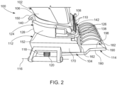
FIG. 2 illustrates a side perspective view of the hair trimmer assembly ofFIG. 1 , in accordance with an embodiment of the disclosure; -
FIG. 3 illustrates a rear perspective view of the hair trimmer assembly ofFIG. 1 , in accordance with an embodiment of the disclosure; -
FIG. 4 illustrates a perspective view of the hair clipper including a body and a guide structure arranged in closed position, in accordance with an embodiment of the disclosure; -
FIG. 5 illustrates a perspective view of the hair clipper ofFIG. 4 depicting the guide structure in an open position, in accordance with an embodiment of the disclosure; and -
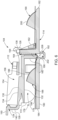
FIG. 6 illustrates a sectional view of the hair clipper showing a hair inside the hair clipper with a split end of the hair extending vertically from a free end of a plate of the guide structure, in accordance with an embodiment of the disclosure. - In the following description, for purposes of explanation, numerous specific details are set forth in order to provide a thorough understanding of the present disclosure. It will be apparent, however, to one skilled in the art that the present disclosure can be practiced without these specific details. In other instances, apparatus and methods are shown in block diagram form only in order to avoid obscuring the present disclosure.
- Reference in this specification to "one embodiment" or "an embodiment" means that a particular feature, structure, or characteristic described in connection with the embodiment is included in at least one embodiment of the present disclosure. The appearance of the phrase "in one embodiment" in various places in the specification are not necessarily all referring to the same embodiment, nor are separate or alternative embodiments mutually exclusive of other embodiments. Further, the terms "a" and "an" herein do not denote a limitation of quantity, but rather denote the presence of at least one of the referenced items. Moreover, various features are described which may be exhibited by some embodiments and not by others. Similarly, various requirements are described which may be requirements for some embodiments but not for other embodiments.
- Some embodiments of the present disclosure will now be described more fully hereinafter with reference to the accompanying drawings, in which some, but not all, embodiments of the disclosure are shown. Indeed, various embodiments of the disclosure may be embodied in many different forms and should not be construed as limited to the embodiments set forth herein; rather, these embodiments are provided so that this disclosure will satisfy applicable legal requirements. Like reference numerals refer to like elements throughout. The use of any term should not be taken to limit the spirit and scope of embodiments of the present disclosure.
- The embodiments are described herein for illustrative purposes and are subject to many variations. It is understood that various omissions and substitutions of equivalents are contemplated as circumstances may suggest or render expedient but are intended to cover the application or implementation without departing from the spirit or the scope of the present disclosure. Further, it is to be understood that the phraseology and terminology employed herein are for the purpose of the description and should not be regarded as limiting. Any heading utilized within this description is for convenience only and has no legal or limiting effect.
- Referring to
FIGS. 1 to 3 , ahair trimmer assembly 100 having ahair trimmer 102 and ahair clipper 104 coupled to thehair trimmer 102 is shown. Thehair trimmer 102 is suitable to cut hairs of a person and includes abody structure 106 adapted to house a plurality of components of thehair trimmer 102 and configured to act as a handle to be held by user while performing a hair cutting operation, and ablade section 108 coupled to an end of thebody structure 106 and includestrimmer blades 110 for cutting the hairs. To facilitate cutting of split ends of the hairs, thehair clipper 104 is removably attached to theblade section 108 of thehair trimmer 102. - As shown in
FIGS. 1 to 6 , thehair clipper 104 includes abody 112 adapted to be removably coupled to theblade section 108 of thehair trimmer 102 and aguide structure 114 pivotally coupled to thebody 112 and adapted to pivot between an open position and a closed position relative to thebody 112 about apivot axis 116 extending in a longitudinal direction. Thehair clipper 104 further includes a biasingmember 118 arranged between thebody 112 and theguide structure 114, biasing theguide structure 114 in the open position. The guide structure is moved to the closed position by applying a force against the biasing force of the biasingmember 118. In the illustrated embodiment, the biasingmember 118 is aspring 120. - To facilitate the coupling of the
hair clipper 104 withhair trimmer 102, as best shown inFIGS. 4 and5 , thebody 112 includes aclamp structure 124 adapted to be clamped/mounted to thehair trimmer 102 and includes a firstlongitudinal end 126 and a secondlongitudinal end 128 disposed opposite to the firstlongitudinal end 126. As shown, theclamp structure 124 includes a bottom 130 extending from the firstlongitudinal end 126 to the secondlongitudinal end 128 and having afirst surface 132 arranged facing theguide structure 114 and asecond surface 134 arranged opposite to thefirst surface 132. Thesecond surface 134 may abut theblade section 108 of thehair trimmer 102 in the assembly of thehair clipper 104 with thehair trimmer 102. - Further, the
clamp structure 124 includes astopper 138 arranged at the firstlongitudinal end 126 and extends substantially perpendicularly (i.e., vertically) from thesecond surface 134 of the bottom 130, and aclip 140 arranged at the secondlongitudinal end 126 and extending substantially perpendicularly (vertically) from thesecond surface 134 of the bottom 130. As shown inFIGS. 4 and5 , thestopper 138 and theclip 140 are arranged spaced apart and facing each other. Also, thestopper 138 defines acavity 142 such afirst stopper structure 144 is defined at a first side of thecavity 142 and asecond stopper structure 146 is defined at a second side of thecavity 142. In an assembly of thehair clipper 104 with thehair trimmer 102, theblade section 108 is arranged between theclip 140 and thestopper 138 such that thetrimmer blades 110 of theblade section 108 extend forwardly of thestopper 138 through thecavity 142, as shown inFIG. 1 . Further, theclip 140 is a flexible clip configured to pivot/flex relative to the bottom in a longitudinal direction between a forward position and a rearward position. Theclip 140 abuts thebody structure 106 of thehair trimmer 102 and hold thehair clipper 104 with thehair trimmer 102 when arranged in the forward position. Accordingly, theclip 140 is flexed/pivoted rearwardly relative to the bottom 130 to the rearward position to disengage the clamp structure 124 (i.e., the hair clipper 104) from thehair trimmer 102. To facilitate the flexing of theclip 140 by a user, theclip 140 includes atab 150 arranged proximate to a free end of theclip 140 and adapted to be held by a user. - Moreover, the
clamp structure 124 includes a firstlongitudinal wall 152 and a secondlongitudinal wall 154 extending in a longitudinal direction between thestopper 138 and theclip 140. As shown, the firstlongitudinal wall 152 and the secondlongitudinal wall 154 are arranged spaced apart from each other and extend vertically from thesecond surface 134 of the bottom 130. Accordingly, aspace 156 is defined between thelongitudinal walls stopper 138 and theclip 140 to receive an end portion of thehair trimmer 102 including theblade section 108. Further, thelongitudinal walls stopper 138 and theclip 140 are arranged such that thelongitudinal walls stopper 138, and theclip 140 engage with thehair trimmer 102 in an assembly of thehair clipper 104 with thehair trimmer 102. - Additionally, the
body 112 includes a first wall 160 (best shown inFIG. 6 ) extending in the lateral direction and arranged proximate to thestopper 138. As shown, thefirst wall 160 extends vertically and outwardly from thefirst surface 132 of the bottom 130. Accordingly, thefirst wall 160 extends in a direction opposite to the extension of thestopper 138 from thebottom 130 of theclamp structure 124. Thefirst wall 160 is configured to push the hairs towards theguide structure 114 when theguide structure 114 is arranged in the closed position. Further, thebody 112 includes asecond wall 162 extending substantially parallel to thefirst wall 160 and arranged spaced apart from thefirst wall 160 and forwardly of thefirst wall 160 as well the firstlongitudinal end 126 of theclamp structure 124. Accordingly, agap 164 is defined between thefirst wall 160 and thesecond wall 162, and thesecond wall 162 is coupled to theclamp structure 124 via a pair ofarms arms clamp structure 124 and are arranged spaced apart from each other. Additionally, a height of thesecond wall 162 is smaller than a height of thefirst wall 160. - Further, as best shown in
FIG. 3 , theclamp structure 124 includes a pair ofsidewalls first surface 132 of the bottom 130 and arranged spaced apart and facing each other. Thesidewalls first wall 160 to the secondlongitudinal end 128 of theclamp structure 124. Accordingly, aspace 176 is defined between thesidewalls first wall 160. Further, anopening 178 of thespace 176 is defined at the secondlongitudinal end 128 and between thesidewalls space 176. The hairs enter thespace 176 through theopening 178, moves in the longitudinal direction through thespace 176, and is pushed towards theguide structure 114 by thefirst wall 160. - Referring to
FIG. 5 , theguide structure 114 includes a base 180 having a first longitudinal end 182 (i.e., front end 182) disposed forwardly of thesecond wall 162 of thebody 112 and a second longitudinal end 184 (i.e., rear end 184). Theguide structure 114 further includes aplate 186, afirst comb structure 188, asecond comb structure 190, and areservoir 192. Theplate 186 extends substantially perpendicularly from the base 180 towards thebottom 130 of theclamp structure 124 and is disposed between thefront end 182 and therear end 184. Moreover, a location of theplate 186 is selected such that theplate 186 is arranged inside thegap 164 defined between thefirst wall 160 and thesecond wall 162 when theguide structure 114 is disposed/arranged in the closed position, as shown inFIG. 4 . Theplate 186 extends in the lateral direction and is configured to push the hairs upwardly towards thetrimmer blades 110 of the hair trimmer. Further, as shown inFIG. 6 , during the hair cutting process, the hair extends over afree end 194 of theplate 186 such that the split end of a hair extends upwardly of thefree end 194 and thereby facilitating the cutting of the split end of the hair by thetrimmer blades 110. - Additionally, the
first comb structure 188 is arranged proximate to therear end 184 of thebase 180, while thesecond comb structure 190 is disposed proximate to thefront end 182 of thebase 180. Moreover, thefirst comb structure 188 is arranged between thereservoir 192 and therear end 184 of the base and is arranged inside thespace 176 in the closed position of theguide structure 114, while thesecond comb structure 190 is disposed forwardly of thebody 112 i.e., thesecond wall 162 of thebody 112. As shown, thefirst comb structure 188 includes a plurality of teeth 196 (i.e., first teeth 196) arranged spaced apart from each other and arrayed in the lateral direction along a width of thebase 180 of theguide structure 114. Theteeth 196 extend upwardly from asurface 198 of thebase 180. Similar to thefirst comb structure 188, thesecond comb structure 190 includes a plurality of teeth 200 (i.e., second teeth 200) arranged spaced apart from each other and arrayed in the lateral direction along a width of thebase 180 of theguide structure 114. Theteeth 200 extend upwardly from the surface of thebase 180 and are arranged proximate to thefront end 182 of thebase 180 and forwardly of thebody 112. - Referring to
FIGS. 4 to 6 , thereservoir 192 defines achamber 202 that is disposed between theplate 186 and the first comb structure 188 (i.e.,rear end 184 of the base 180) and is arranged adjacent to theplate 186 such that the hairs pushed by thefirst wall 160 towards thebase 180, in the closed position of theguide structure 114, extends inside thechamber 202. A conditioner is disposed inside thechamber 202 to condition the hairs that pass through thechamber 202. In an embodiment, thereservoir 192 includes asponge 206 arranged inside thechamber 202 with the conditioner absorbed inside thesponge 206. Accordingly, the conditioner sticks to the hair as the hair passes through thechamber 202, contacting thesponge 206. In some embodiments, the conditioner may be in a semi-solid or solid form and the is arranged inside thechamber 202 without using thesponge 206. - A method for removing or cutting the split ends of the hairs using the
hair trimmer assembly 100 is now described. The method includes mounting thehair clipper 104 to theblade section 108 of thehair trimmer 102 by arranging theblade section 108 inside thespace 156 of theclamp structure 124 such that thetrimmer blades 110 extend forwardly of thefirst wall 160 and inside thegap 164 defined between thefirst wall 160 and thesecond wall 162. Thereafter, thehair clipper 104 is engaged with the hairs such that therear end 184 of thebase 180 of theguide structure 114 is arranged proximate to the roots of the hairs (i.e., scalp of the head of the user), while thefront end 182 of thebase 180 of theguide structure 180 is arranged relatively distally from the roots of the hairs. However, a reverse orientation of thehair clipper 104 is also possible for cutting the hairs. Thehair clipper 104 is engaged with the hairs such that a portion of the hairs is disposed between thebody 112 and theguide structure 114 and front parts of the hair extend forwardly of the hair clipper 104 (i.e., forwardly of thesecond wall 162 of the body 112) and rear parts (parts relatively closer to roots of the hairs) of hairs extend rearwardly of the hair clipper 104 (i.e. opening 178), as shown inFIG. 6 . Moreover, as shown inFIG. 6 , the portions of hairs arranged inside thespace 176 are arranged underneath thefirst wall 160 and inside thechamber 202. Moreover, portions of hairs extend vertically between thefirst wall 160 and theplate 186, and the split ends of the hairs protrude vertically above thefree end 194 of theplate 186. Accordingly, as the hair clipper 104 (i.e., hair trimmer assembly 100) is moved towards the free ends of the hairs, protruding split ends of the hairs are cut by thetrimmer blades 110, at first. Thereafter, the cut hairs move downwardly and underneath thefirst wall 160 that pushes the cut hairs inside thechamber 202, coating the cut hairs with the conditioner. Subsequently, the hairs move through theteeth 196 of thefirst comb structure 190 to prevent any entanglement of the hairs. - In an embodiment in which the
hair clipper 104 is engaged with the hairs in the reverse orientation to cut the split ends of the hairs. In such an orientation, as the hair clipper 104 (i.e., hair trimmer assembly 100) is moved towards the free ends of the hairs, the hairs pass through thechamber 202, gets coated with the conditioner, and move vertically towards thefree end 194 of theplate 186. At thefree end 194 of theplate 186, the protruding split ends of the hairs are cut by thetrimmer blades 110. Thereafter, the cut hairs move downwardly and underneath thesecond wall 162 and out of thebody 112. Subsequently, the hairs move through theteeth 200 of thesecond comb structure 190 to prevent any entanglement of the hairs. In this manner, thehair clipper 104 facilitates easy cutting of the split ends of the hairs along with the conditioning of the hairs. - Many modifications and other embodiments of the disclosures set forth herein will come to mind to one skilled in the art to which these disclosures pertain having the benefit of the teachings presented in the foregoing descriptions and the associated drawings. Therefore, it is to be understood that the disclosures are not to be limited to the specific embodiments disclosed and that modifications and other embodiments are intended to be included within the scope of the appended claims. Moreover, although the foregoing descriptions and the associated drawings describe example embodiments in the context of certain example combinations of elements and/or functions, it should be appreciated that different combinations of elements and/or functions may be provided by alternative embodiments without departing from the scope of the appended claims. In this regard, for example, different combinations of elements and/or functions than those explicitly described above are also contemplated as may be set forth in some of the appended claims. Although specific terms are employed herein, they are used in a generic and descriptive sense only and not for purposes of limitation.
Claims (15)
- A hair clipper (104) for a hair trimmer (102), comprising:a body (112) includinga clamp structure (124) configured to removably clamp to a blade section (108) of the hair trimmer (102) and having a first longitudinal end (126) and a second longitudinal end (128),a first wall (160) arranged proximate to the first longitudinal end (126) of the clamp structure (124) and extending substantially perpendicularly from the clamp structure (124), wherein the first wall (160) extends in a lateral direction, anda second wall (162) arranged substantially parallel to and spaced apart from the first wall (160) defining a gap (164) therebetween, the second wall (162) being arranged forwardly of the first longitudinal end (126) and is coupled to the clamp structure (124); anda guide structure (114) pivotally coupled to the body (112) and adapted to move between an open position and a closed position relative to the body (112), the guide structure (114) includescharacterized in thata base (180) having a front end (182) and a rear end (184),a plate (186) extending substantially perpendicularly from the base (180) towards the clamp structure (124), wherein the plate (186) is arranged between the first wall (160) and the second wall (162) in the closed position of the guide structure (114), anda reservoir (192) defining a chamber (202) arranged between the plate (186) and the rear end (184) of the base (180) with a conditioner disposed inside the chamber (202),wherein in the closed position of the guide structure (114), the first wall (160) of the body (112) pushes a plurality of hairs inside the chamber (202) and the plate (186) of the guide structure (114) guides the plurality of hairs towards trimmer blades (110) to remove split end of one or more of the plurality of hairs.
- The hair clipper (104) of claim 1 further comprises a biasing member (118) arranged between the body (112) and the guide structure (114) and biasing the guide structure (114) to the open position.
- The hair clipper (104) of claim 1 or claim 2, wherein the clamp structure (124) includes a bottom (130) having a first surface (132) arranged facing the base (180) of the guide structure (114) and a second surface (134) arranged opposite to the first surface (132) and configured to abut at least a portion of the blade section (108) of the hair trimmer (102).
- The hair clipper (104) of claim 3, wherein the clamp structure (124) includesa stopper (138) arranged at the first longitudinal end (126) of the clamp structure (124) and extending vertically from the second surface (134) of the bottom (130) and defining a cavity (142),a clip (140) arranged at the second longitudinal end (128) and extending vertically from the second surface (134) and adapted to be pivoted between a forward position and a rearward position relative to the bottom (130) to enable a clamping and removal of the hair clipper (104) with the blade section (108) of the hair trimmer (102),wherein the blade section (108) is arranged between the stopper (138) and the clip (140) such that the trimmer blades (110) extend forwardly of the stopper (138) through the cavity (142) in an assembly of the hair trimmer (102) with the clamp structure (124).
- The hair clipper (104) of claim 3 or claim 4, wherein the clamp structure (124) includes a pair of sidewalls (170, 172) extending vertically outwardly from the first surface (132) of the bottom (130) and arranged space apart from each other defining a space (176) for containing the plurality of hairs, wherein the first wall (160) is disposed perpendicularly to the pair of sidewalls (170, 172).
- The hair clipper (104) of any one of preceding claims, wherein the guide structure (114) includes a first comb structure (188) having a plurality of first teeth (196) extending vertically from the base (180) and arrayed in the lateral direction, wherein the first teeth (196) are arranged proximate to the rear end (184) of the base (180).
- The hair clipper (104) of any one of preceding claims, wherein the guide structure (114) includes a second comb structure (190) having a plurality of second teeth (200) extending vertically from the base (180) and arrayed in the lateral direction, wherein the second teeth (200) are arranged proximate to the front end (182) of the base (180) and are disposed forwardly of the clamp structure (124).
- The hair clipper (104) of any one of preceding claims, wherein the reservoir (192) includes a sponge (206) arranged inside the chamber (202) with the conditioner absorbed inside the sponge (206).
- A hair trimmer assembly (100), comprising:a hair trimmer (102) including a blade section (108); anda hair clipper (104) removably coupled to the blade section (108) of the hair trimmer (102) and havingcharacterized in thata body (112) includinga clamp structure (124) removably clamped to the blade section (108) of the hair trimmer (102) and having a first longitudinal end (126) and a second longitudinal end (128),a first wall (160) arranged proximate to the first longitudinal end (126) of the clamp structure (124) and extending substantially perpendicularly from the clamp structure (124), wherein the first wall (160) extends in a lateral direction, anda second wall (162) arranged substantially parallel to and spaced apart from the first wall (160) defining a gap (164) therebetween, the second wall (162) being arranged forwardly of the first longitudinal end (126) and is coupled to the clamp structure (124), anda guide structure (114) pivotally coupled to the body (112) and adapted to move between an open position and a closed position relative to the body (112), the guide structure (114) includesa base (180) having a front end (182) and a rear end (184),a plate (186) extending substantially perpendicularly from the base (180) towards the clamp structure (124), wherein the plate (186) is arranged between the first wall (160) and the second wall (162) in the closed position of the guide structure (114), anda reservoir (192) defining a chamber (202) arranged between the plate (186) and the rear end (184) of the base (180) with a conditioner disposed inside the chamber (202),wherein in the closed position of the guide structure (114), the first wall (160) of the body (112) pushes a plurality of hairs inside the chamber (202) and the plate (186) of the guide structure (114) guides the plurality of hairs towards trimmer blades (110) to remove split end of one or more of the plurality of hairs.
- The hair trimmer assembly (100) of claim 9 further comprises a biasing member (118) arranged between the body (112) and the guide structure (114) and biasing the guide structure (114) to the open position.
- The hair trimmer assembly (100) of claim 9 or claim 10, wherein the clamp structure (124) includes a bottom (130) having a first surface (132) arranged facing the base (180) of the guide structure (114) and a second surface (134) arranged opposite to the first surface (132) and configured to abut at least a portion of the blade section (108) of the hair trimmer (102).
- The hair trimmer assembly (100) of claim 11, wherein the clamp structure (124) includesa stopper (138) arranged at the first longitudinal end (126) of the clamp structure (124) and extending vertically from the second surface (134) of the bottom (130) and defining a cavity (142),a clip (140) arranged at the second longitudinal end (128) and extending vertically from the second surface (134) and adapted to be pivoted between a forward position and a rearward position relative to the bottom (130) to enable a clamping and removal of the hair clipper (104) with the blade section (108) of the hair trimmer (102),wherein the blade section (108) is arranged between the stopper (138) and the clip (140) such that the trimmer blades (110) extend forwardly of the stopper (138) through the cavity (142) in an assembly of the hair trimmer (102) with the clamp structure (124).
- The hair trimmer assembly (100) of claim 11 or claim 12, wherein the clamp structure (124) includes a pair of sidewalls (170, 172) extending vertically outwardly from the first surface (132) of the bottom (130) and arranged space apart from each other defining a space (176) for containing the plurality of hairs, wherein the first wall (160) is disposed perpendicularly to the pair of sidewalls (170, 172).
- The hair trimmer assembly (100) of any one of claims 9 to 13, wherein the guide structure (114) includesa first comb structure (188) having a plurality of first teeth (196) extending vertically from the base (180) and arrayed in the lateral direction, wherein the first teeth (196) are arranged proximate to the rear end (184) of the base (180), anda second comb structure (190) having a plurality of second teeth (200) extending vertically from the base (180) and arrayed in the lateral direction, wherein the second teeth (200) are arranged proximate to the front end (182) of the base (180) and are disposed forwardly of the clamp structure (124).
- The hair trimmer assembly (100) of any one of claims 9 to 14, wherein the reservoir (192) includes a sponge (206) arranged inside the chamber (202) with the conditioner absorbed inside the sponge (206).
Priority Applications (1)
| Application Number | Priority Date | Filing Date | Title |
|---|---|---|---|
| EP23187755.6A EP4497557B1 (en) | 2023-07-26 | 2023-07-26 | HAIR CUTTING MACHINE |
Applications Claiming Priority (1)
| Application Number | Priority Date | Filing Date | Title |
|---|---|---|---|
| EP23187755.6A EP4497557B1 (en) | 2023-07-26 | 2023-07-26 | HAIR CUTTING MACHINE |
Publications (2)
| Publication Number | Publication Date |
|---|---|
| EP4497557A1 true EP4497557A1 (en) | 2025-01-29 |
| EP4497557B1 EP4497557B1 (en) | 2025-12-31 |
Family
ID=87473929
Family Applications (1)
| Application Number | Title | Priority Date | Filing Date |
|---|---|---|---|
| EP23187755.6A Active EP4497557B1 (en) | 2023-07-26 | 2023-07-26 | HAIR CUTTING MACHINE |
Country Status (1)
| Country | Link |
|---|---|
| EP (1) | EP4497557B1 (en) |
Citations (3)
| Publication number | Priority date | Publication date | Assignee | Title |
|---|---|---|---|---|
| US5237750A (en) * | 1991-05-28 | 1993-08-24 | Matsushita Electric Works, Ltd. | Hair clipper |
| WO2016010462A1 (en) * | 2014-07-15 | 2016-01-21 | Евгений Владимирович ШМИДТ | Attachment for trimming the ends of long hairs |
| WO2017217886A1 (en) * | 2016-06-16 | 2017-12-21 | Shmidt Evgeny Vladimirovich | Attachment for cutting the hair ends |
-
2023
- 2023-07-26 EP EP23187755.6A patent/EP4497557B1/en active Active
Patent Citations (3)
| Publication number | Priority date | Publication date | Assignee | Title |
|---|---|---|---|---|
| US5237750A (en) * | 1991-05-28 | 1993-08-24 | Matsushita Electric Works, Ltd. | Hair clipper |
| WO2016010462A1 (en) * | 2014-07-15 | 2016-01-21 | Евгений Владимирович ШМИДТ | Attachment for trimming the ends of long hairs |
| WO2017217886A1 (en) * | 2016-06-16 | 2017-12-21 | Shmidt Evgeny Vladimirovich | Attachment for cutting the hair ends |
Also Published As
| Publication number | Publication date |
|---|---|
| EP4497557B1 (en) | 2025-12-31 |
Similar Documents
| Publication | Publication Date | Title |
|---|---|---|
| US6862810B2 (en) | Hair-trimmer with releasable cutting head | |
| EP3225369B1 (en) | Comb attachment for hair clippers | |
| US12145283B2 (en) | Attachment comb and hair cutting appliance | |
| EP2326469B1 (en) | Hair trimmers | |
| JP6725770B2 (en) | Comb configuration, cutting head and hair cutting device | |
| JP6188959B2 (en) | Attachment comb and hair cutting equipment | |
| CN108349098B (en) | Handle assembly, cartridge and shaver comprising these | |
| US4782590A (en) | Personal grooming device | |
| US6249973B1 (en) | Thinning razor | |
| JPH0815509B2 (en) | Hair clipper | |
| US20070006463A1 (en) | Integrated wet shaving and trimming implement | |
| US5479950A (en) | Finger tip mustache shaving device with cover | |
| US20200221848A1 (en) | Comb with magnifying lens | |
| EP4497557A1 (en) | Hair clipper | |
| US5727318A (en) | Clippers for fingernails | |
| CN218313646U (en) | An improved shearing razor device | |
| US4514903A (en) | Personal grooming device | |
| JP2022552454A (en) | sharpener | |
| CN215903552U (en) | Tool bit subassembly and hair trimmer | |
| KR100582029B1 (en) | Hairdressing scissors | |
| JP3515978B1 (en) | Hairdresser | |
| US8887400B2 (en) | Protective riser guide for scissors | |
| US20160046027A1 (en) | Hair Bang Clipper | |
| JP3018615U (en) | Comb with blade for hair cutting | |
| GB2430905A (en) | Razor with hinge perpendicular to cutting edge |
Legal Events
| Date | Code | Title | Description |
|---|---|---|---|
| PUAI | Public reference made under article 153(3) epc to a published international application that has entered the european phase |
Free format text: ORIGINAL CODE: 0009012 |
|
| STAA | Information on the status of an ep patent application or granted ep patent |
Free format text: STATUS: THE APPLICATION HAS BEEN PUBLISHED |
|
| AK | Designated contracting states |
Kind code of ref document: A1 Designated state(s): AL AT BE BG CH CY CZ DE DK EE ES FI FR GB GR HR HU IE IS IT LI LT LU LV MC ME MK MT NL NO PL PT RO RS SE SI SK SM TR |
|
| STAA | Information on the status of an ep patent application or granted ep patent |
Free format text: STATUS: REQUEST FOR EXAMINATION WAS MADE |
|
| 17P | Request for examination filed |
Effective date: 20250716 |
|
| RIC1 | Information provided on ipc code assigned before grant |
Ipc: B26B 19/20 20060101AFI20250904BHEP Ipc: B26B 19/22 20060101ALI20250904BHEP Ipc: B26B 19/38 20060101ALI20250904BHEP |
|
| GRAP | Despatch of communication of intention to grant a patent |
Free format text: ORIGINAL CODE: EPIDOSNIGR1 |
|
| STAA | Information on the status of an ep patent application or granted ep patent |
Free format text: STATUS: GRANT OF PATENT IS INTENDED |
|
| GRAS | Grant fee paid |
Free format text: ORIGINAL CODE: EPIDOSNIGR3 |
|
| GRAA | (expected) grant |
Free format text: ORIGINAL CODE: 0009210 |
|
| STAA | Information on the status of an ep patent application or granted ep patent |
Free format text: STATUS: THE PATENT HAS BEEN GRANTED |
|
| INTG | Intention to grant announced |
Effective date: 20251103 |
|
| AK | Designated contracting states |
Kind code of ref document: B1 Designated state(s): AL AT BE BG CH CY CZ DE DK EE ES FI FR GB GR HR HU IE IS IT LI LT LU LV MC ME MK MT NL NO PL PT RO RS SE SI SK SM TR |
|
| REG | Reference to a national code |
Ref country code: CH Ref legal event code: F10 Free format text: ST27 STATUS EVENT CODE: U-0-0-F10-F00 (AS PROVIDED BY THE NATIONAL OFFICE) Effective date: 20251231 Ref country code: GB Ref legal event code: FG4D |
|
| REG | Reference to a national code |
Ref country code: DE Ref legal event code: R096 Ref document number: 602023010313 Country of ref document: DE |
|
| REG | Reference to a national code |
Ref country code: IE Ref legal event code: FG4D |
|
| P01 | Opt-out of the competence of the unified patent court (upc) registered |
Free format text: CASE NUMBER: UPC_APP_0000320_4497557/2026 Effective date: 20260106 |
|
| REG | Reference to a national code |
Ref country code: LT Ref legal event code: MG9D |
|
| PG25 | Lapsed in a contracting state [announced via postgrant information from national office to epo] |
Ref country code: NO Free format text: LAPSE BECAUSE OF FAILURE TO SUBMIT A TRANSLATION OF THE DESCRIPTION OR TO PAY THE FEE WITHIN THE PRESCRIBED TIME-LIMIT Effective date: 20260331 |
|
| PG25 | Lapsed in a contracting state [announced via postgrant information from national office to epo] |
Ref country code: FI Free format text: LAPSE BECAUSE OF FAILURE TO SUBMIT A TRANSLATION OF THE DESCRIPTION OR TO PAY THE FEE WITHIN THE PRESCRIBED TIME-LIMIT Effective date: 20251231 Ref country code: HR Free format text: LAPSE BECAUSE OF FAILURE TO SUBMIT A TRANSLATION OF THE DESCRIPTION OR TO PAY THE FEE WITHIN THE PRESCRIBED TIME-LIMIT Effective date: 20251231 |
|
| PG25 | Lapsed in a contracting state [announced via postgrant information from national office to epo] |
Ref country code: RS Free format text: LAPSE BECAUSE OF FAILURE TO SUBMIT A TRANSLATION OF THE DESCRIPTION OR TO PAY THE FEE WITHIN THE PRESCRIBED TIME-LIMIT Effective date: 20260331 |
|
| PG25 | Lapsed in a contracting state [announced via postgrant information from national office to epo] |
Ref country code: LV Free format text: LAPSE BECAUSE OF FAILURE TO SUBMIT A TRANSLATION OF THE DESCRIPTION OR TO PAY THE FEE WITHIN THE PRESCRIBED TIME-LIMIT Effective date: 20251231 |