EP4497530A1 - Machining of ceramic matrix composites with curved waterjet guided laser - Google Patents
Machining of ceramic matrix composites with curved waterjet guided laser Download PDFInfo
- Publication number
- EP4497530A1 EP4497530A1 EP24180285.9A EP24180285A EP4497530A1 EP 4497530 A1 EP4497530 A1 EP 4497530A1 EP 24180285 A EP24180285 A EP 24180285A EP 4497530 A1 EP4497530 A1 EP 4497530A1
- Authority
- EP
- European Patent Office
- Prior art keywords
- waterjet
- workpiece
- electrode
- voltage
- guided laser
- Prior art date
- Legal status (The legal status is an assumption and is not a legal conclusion. Google has not performed a legal analysis and makes no representation as to the accuracy of the status listed.)
- Pending
Links
Images



Classifications
-
- B—PERFORMING OPERATIONS; TRANSPORTING
- B23—MACHINE TOOLS; METAL-WORKING NOT OTHERWISE PROVIDED FOR
- B23K—SOLDERING OR UNSOLDERING; WELDING; CLADDING OR PLATING BY SOLDERING OR WELDING; CUTTING BY APPLYING HEAT LOCALLY, e.g. FLAME CUTTING; WORKING BY LASER BEAM
- B23K26/00—Working by laser beam, e.g. welding, cutting or boring
- B23K26/14—Working by laser beam, e.g. welding, cutting or boring using a fluid stream, e.g. a jet of gas, in conjunction with the laser beam; Nozzles therefor
- B23K26/146—Working by laser beam, e.g. welding, cutting or boring using a fluid stream, e.g. a jet of gas, in conjunction with the laser beam; Nozzles therefor the fluid stream containing a liquid
-
- B—PERFORMING OPERATIONS; TRANSPORTING
- B23—MACHINE TOOLS; METAL-WORKING NOT OTHERWISE PROVIDED FOR
- B23K—SOLDERING OR UNSOLDERING; WELDING; CLADDING OR PLATING BY SOLDERING OR WELDING; CUTTING BY APPLYING HEAT LOCALLY, e.g. FLAME CUTTING; WORKING BY LASER BEAM
- B23K26/00—Working by laser beam, e.g. welding, cutting or boring
- B23K26/12—Working by laser beam, e.g. welding, cutting or boring in a special environment or atmosphere, e.g. in an enclosure
- B23K26/122—Working by laser beam, e.g. welding, cutting or boring in a special environment or atmosphere, e.g. in an enclosure in a liquid, e.g. underwater
-
- B—PERFORMING OPERATIONS; TRANSPORTING
- B23—MACHINE TOOLS; METAL-WORKING NOT OTHERWISE PROVIDED FOR
- B23K—SOLDERING OR UNSOLDERING; WELDING; CLADDING OR PLATING BY SOLDERING OR WELDING; CUTTING BY APPLYING HEAT LOCALLY, e.g. FLAME CUTTING; WORKING BY LASER BEAM
- B23K26/00—Working by laser beam, e.g. welding, cutting or boring
- B23K26/02—Positioning or observing the workpiece, e.g. with respect to the point of impact; Aligning, aiming or focusing the laser beam
- B23K26/06—Shaping the laser beam, e.g. by masks or multi-focusing
- B23K26/064—Shaping the laser beam, e.g. by masks or multi-focusing by means of optical elements, e.g. lenses, mirrors or prisms
-
- B—PERFORMING OPERATIONS; TRANSPORTING
- B23—MACHINE TOOLS; METAL-WORKING NOT OTHERWISE PROVIDED FOR
- B23K—SOLDERING OR UNSOLDERING; WELDING; CLADDING OR PLATING BY SOLDERING OR WELDING; CUTTING BY APPLYING HEAT LOCALLY, e.g. FLAME CUTTING; WORKING BY LASER BEAM
- B23K26/00—Working by laser beam, e.g. welding, cutting or boring
- B23K26/36—Removing material
- B23K26/38—Removing material by boring or cutting
-
- B—PERFORMING OPERATIONS; TRANSPORTING
- B23—MACHINE TOOLS; METAL-WORKING NOT OTHERWISE PROVIDED FOR
- B23K—SOLDERING OR UNSOLDERING; WELDING; CLADDING OR PLATING BY SOLDERING OR WELDING; CUTTING BY APPLYING HEAT LOCALLY, e.g. FLAME CUTTING; WORKING BY LASER BEAM
- B23K26/00—Working by laser beam, e.g. welding, cutting or boring
- B23K26/36—Removing material
- B23K26/38—Removing material by boring or cutting
- B23K26/382—Removing material by boring or cutting by boring
- B23K26/389—Removing material by boring or cutting by boring of fluid openings, e.g. nozzles, jets
-
- B—PERFORMING OPERATIONS; TRANSPORTING
- B23—MACHINE TOOLS; METAL-WORKING NOT OTHERWISE PROVIDED FOR
- B23K—SOLDERING OR UNSOLDERING; WELDING; CLADDING OR PLATING BY SOLDERING OR WELDING; CUTTING BY APPLYING HEAT LOCALLY, e.g. FLAME CUTTING; WORKING BY LASER BEAM
- B23K26/00—Working by laser beam, e.g. welding, cutting or boring
- B23K26/36—Removing material
- B23K26/40—Removing material taking account of the properties of the material involved
-
- B—PERFORMING OPERATIONS; TRANSPORTING
- B26—HAND CUTTING TOOLS; CUTTING; SEVERING
- B26F—PERFORATING; PUNCHING; CUTTING-OUT; STAMPING-OUT; SEVERING BY MEANS OTHER THAN CUTTING
- B26F1/00—Perforating; Punching; Cutting-out; Stamping-out; Apparatus therefor
- B26F1/26—Perforating by non-mechanical means, e.g. by fluid jet
-
- B—PERFORMING OPERATIONS; TRANSPORTING
- B26—HAND CUTTING TOOLS; CUTTING; SEVERING
- B26F—PERFORATING; PUNCHING; CUTTING-OUT; STAMPING-OUT; SEVERING BY MEANS OTHER THAN CUTTING
- B26F3/00—Severing by means other than cutting; Apparatus therefor
- B26F3/004—Severing by means other than cutting; Apparatus therefor by means of a fluid jet
-
- B—PERFORMING OPERATIONS; TRANSPORTING
- B23—MACHINE TOOLS; METAL-WORKING NOT OTHERWISE PROVIDED FOR
- B23K—SOLDERING OR UNSOLDERING; WELDING; CLADDING OR PLATING BY SOLDERING OR WELDING; CUTTING BY APPLYING HEAT LOCALLY, e.g. FLAME CUTTING; WORKING BY LASER BEAM
- B23K2101/00—Articles made by soldering, welding or cutting
- B23K2101/001—Turbines
-
- B—PERFORMING OPERATIONS; TRANSPORTING
- B23—MACHINE TOOLS; METAL-WORKING NOT OTHERWISE PROVIDED FOR
- B23K—SOLDERING OR UNSOLDERING; WELDING; CLADDING OR PLATING BY SOLDERING OR WELDING; CUTTING BY APPLYING HEAT LOCALLY, e.g. FLAME CUTTING; WORKING BY LASER BEAM
- B23K2103/00—Materials to be soldered, welded or cut
- B23K2103/50—Inorganic materials other than metals or composite materials
- B23K2103/52—Ceramics
Definitions
- the present invention relates to ceramic matrix composites (CMCs), and more particularly, to means of machining CMCs.
- CMCs are extremely hard and brittle and can therefore be hard to machine efficiently.
- Waterjet guided laser is considered as a promising manufacturing route for producing complex 3D holes.
- CAM computer aided manufacturing
- a method of machining a feature in a workpiece includes orienting a waterjet guided laser device about the workpiece, ejecting a waterjet from a nozzle of the waterjet guided laser device, impinging the waterjet against the workpiece along a tool path causing a corresponding removal of material therefrom, and generating a non-uniform electric field proximate the waterjet to cause a deflection of the waterjet as the waterjet is impinging against the workpiece.
- a system for machining a feature in a workpiece includes a holder for securing the workpiece and a waterjet guided laser device translatable relative to the workpiece.
- the waterjet guided laser device includes a nozzle for ejecting a waterjet, the waterjet having a laser beam, and at least one electrode disposed downstream of the nozzle.
- the system further includes a control module operatively connected to the waterjet guided laser device for selectively applying a voltage at a desired frequency to the at least one electrode to cause deflection of the waterjet corresponding to a tool path.
- a method of machining a feature in a workpiece which the Applicant reserves the right to claim independently, includes orienting a waterjet guided laser device about the workpiece, ejecting a waterjet from a nozzle of the waterjet guided laser device, impinging the waterjet against the workpiece along a tool path causing a corresponding removal of material therefrom, and generating a non-uniform electric field proximate the waterjet to cause a deflection of the waterjet as the waterjet is impinging against the workpiece.
- the deflection of the waterjet follows the tool path.
- This disclosure presents means for controlling waterjet trajectory for machining 3D features (e.g., holes, pockets, slots, etc.) in CMCs, which makes it possible to use waterjet guided laser for machining complex 3D shaped features using a continuous toolpath. This improves the efficiency of the laser machining process, especially when the approach is used for machining 3D shaped holes. By accurately controlling waterjet trajectory, this technology could also be used to machine non-line-of-sight features.
- 3D features e.g., holes, pockets, slots, etc.
- FIG. 1 is a simplified illustration of waterjet guided laser device 10.
- Device 10 includes laser beam 12 from a laser source, focusing lens 14, window 16, pressurized water chamber 18, and nozzle 20.
- laser beam 12 is focused by focusing lens 14 and window 16 as it reaches pressurized water chamber 18, filled with pressurized water.
- Cylindrical waterjet 22 with internally reflected laser beam 12 is ejected from nozzle 20 and impinges upon workpiece 24 causing removal of workpiece material along a predetermined tool path.
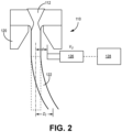
- FIG. 2 is a simplified illustration of waterjet guided laser device 110 in the region of nozzle 120.
- Device 110 is substantially similar to device 10, except that device 110 includes at least one electrode 126 downstream of nozzle.
- Electrode 126 can be controlled to create a non-uniform electric field to deflect, or bend waterjet 122 by dielectrophoresis (DEP).
- DEP occurs when a polarizable particle is suspended in a non-uniform electric field. The electric field polarizes the particle and the poles then experience a force along the field lines, which can be either attractive or repulsive according to the orientation on the dipole. As shown in FIG.
- d represents the distance between electrode 126 and the centerline of waterjet 122 and D f is the deflection of waterjet 122.
- voltage control can be carried out using an amplifier with an output voltage ranging from 0 V to 1400 V, a slew rate of 370 V/ps, and a large signal bandwidth greater than 125 kHz.
- Such an amplifier could be included as part of control module 128, which can be operably connected to device 110 to control the operation of waterjet 122 and electrode(s) 126.
- FIG. 3 is a top-down view of drilling system 130 which includes device 110 and holder 132 for securing workpiece 124.
- workpiece 124 is an airfoil.
- Waterjet 122 of device 110 can be selectively deflected, as discussed above, to drill non-line of sight metering holes 134 in workpiece 124 without the need to frequently reposition device 110 or workpiece 124 relative to one another, which can lead to misalignment between a non-deflected waterjet 122 and the axes of metering holes 134.
- workpiece 124 can remain static while metering holes are drilled by deflection of waterjet 122 with minimal movement of device 110 required. This can be preferable as the mass of system 130 presents inertial challenges with respect to the tool paths necessary to drill complex features (e.g., holes 132). Accordingly, the relatively low inertia of waterjet 122 allows it to be more responsive to directional changes.
- FIG. 4 is a simplified illustration of waterjet guided laser device 210 with multiple electrodes for deflecting waterjet 222.
- Device 210 is otherwise substantially similar to devices 10 and 110.
- Device 210 includes first electrode pair 226-1 oriented along the x-axis, and second electrode pair 226-2 oriented along the y-axis. Each electrode pair 226-1 is oppositely disposed relative to water jet 222, and each electrode pair 226-2 is also oppositely disposed relative to waterjet 222.
- Each electrode pair 226-1 and 226-2 can have a positive (+) electrode and a negative (-) electrode.
- device 210 can include additional electrode pairs (e.g., 226-3, represented by dashed lines, to 226- n ) variably offset from the x and y-axes.
- Device 110 can be similarly configured. Device 210 may be preferable for creating intricate spiral patterns or curved holes in a workpiece, as is discussed below with respect to FIGS. 5 and 6 .
- FIG. 5 is a simplified illustration of metering hole 234 having metering section 236 and diffuser section 238.
- FIG. 5 also illustrates spiral pattern 240, which corresponds to cross-sectional plane 242 of diffuser section 238.
- Spiral pattern 240 can be formed by the inside-out movement of waterjet 222 from point 244 to point 246.
- electrode pairs 226-1 and 226-2 can be selectively operated to deflect the waterjet in a spiral tool path in the x-y plane without the need to translate the underlying workpiece, and with little to no movement of device 210 required.
- Other sectional planes corresponding to metering section 236 and diffuser section 238 can be similarly drilled to form metering hole 234.
- FIG. 6 is a simplified illustration of a portion of waterjet guided laser device 210 forming curved cooling hole 248 in workpiece 224, which can be an airfoil or other component for a gas turbine engine. Only first electrode pair 226-1 is visible in FIG. 6 .
- a control module e.g., control module 128, can operate to variably apply voltage to electrode pairs 226-1 and 226-2 according to a pre-programmed tool path.
- the combination of the positively charged and negatively charged electrodes of a given pair e.g., 226-1) can deflect waterjet 222 in the same direction, as one acts to repel and the other to attract waterjet 222.
- Such means of controlling the electric field therefore allow deflection of waterjet 222 to follow the tool path necessary to machine complex features.
- the disclosed waterjet guided laser devices can be used to form non-line of sight and/or complexly shaped holes in CMC components for use in aerospace, maritime, or industrial equipment, to name a few, non-limiting examples.
- a method of machining a feature in a workpiece includes orienting a waterjet guided laser device about the workpiece, ejecting a waterjet from a nozzle of the waterjet guided laser device, impinging the waterjet against the workpiece along a tool path causing a corresponding removal of material therefrom, and generating a non-uniform electric field proximate the waterjet to cause a deflection of the waterjet as the waterjet is impinging against the workpiece.
- generating the non-uniform electric field can include selectively applying a voltage to at least one electrode, the at least one electrode positioned downstream of the nozzle.
- the voltage can range from 0 to 1400.
- the at least one electrode can include a first electrode pair disposed along a first axis and a second electrode pair disposed along an orthogonal second axis.
- generating the non-uniform electric field can include selectively applying a voltage to the first electrode pair and the second electrode pair.
- generating the non-uniform electric field can further include varying at least one of a frequency and an amplitude of the voltage.
- generating the non-uniform electric field can include reversing a polarity of the first electrode pair or of the second electrode pair.
- the tool path can form a curved cooling hole.
- the tool path can form a spiral pattern.
- Any of the above methods can further include mounting the workpiece in a holder and keeping the workpiece stationary while impinging the waterjet against the workpiece.
- a system for machining a feature in a workpiece includes a holder for securing the workpiece and a waterjet guided laser device translatable relative to the workpiece.
- the waterjet guided laser device includes a nozzle for ejecting a waterjet, the waterjet having a laser beam, and at least one electrode disposed downstream of the nozzle.
- the system further includes a control module operatively connected to the waterjet guided laser device for selectively applying a voltage at a desired frequency to the at least one electrode to cause deflection of the waterjet corresponding to a tool path.
- the at least one electrode can include a first electrode pair disposed along a first axis.
- the at least one electrode can further include a second electrode pair disposed along an orthogonal second axis.
- the voltage can range from 0 to 1400.
- the voltage can be one of a DC voltage and a DC-biased AC voltage.
- a method of machining a feature in a workpiece includes orienting a waterjet guided laser device about the workpiece, ejecting a waterjet from a nozzle of the waterjet guided laser device, impinging the waterjet against the workpiece along a tool path causing a corresponding removal of material therefrom, and generating a non-uniform electric field proximate the waterjet to cause a deflection of the waterjet as the waterjet is impinging against the workpiece.
- the deflection of the waterjet follows the tool path.
- generating the non-uniform electric field can include applying a voltage to the at least one electrode, and controlling at least one of an amplitude or a frequency of the voltage.
- the voltage can range from 0 to 1400.
- generating the non-uniform electric field can include reversing a polarity of the first electrode pair of the second electrode pair.
Landscapes
- Engineering & Computer Science (AREA)
- Physics & Mathematics (AREA)
- Optics & Photonics (AREA)
- Mechanical Engineering (AREA)
- Plasma & Fusion (AREA)
- Life Sciences & Earth Sciences (AREA)
- Forests & Forestry (AREA)
- Laser Beam Processing (AREA)
- Electrical Discharge Machining, Electrochemical Machining, And Combined Machining (AREA)
Abstract
Description
- The present invention relates to ceramic matrix composites (CMCs), and more particularly, to means of machining CMCs.
- CMCs are extremely hard and brittle and can therefore be hard to machine efficiently. Waterjet guided laser is considered as a promising manufacturing route for producing complex 3D holes. However, due to the non-contact nature of laser ablation, it can be difficult to generate a toolpath for complex 3D shapes with existing computer aided manufacturing (CAM) systems, which subsequently limits its application for 3D machining. Thus, it is necessary to develop a method to overcome the disadvantages.
- A method of machining a feature in a workpiece includes orienting a waterjet guided laser device about the workpiece, ejecting a waterjet from a nozzle of the waterjet guided laser device, impinging the waterjet against the workpiece along a tool path causing a corresponding removal of material therefrom, and generating a non-uniform electric field proximate the waterjet to cause a deflection of the waterjet as the waterjet is impinging against the workpiece.
- A system for machining a feature in a workpiece includes a holder for securing the workpiece and a waterjet guided laser device translatable relative to the workpiece. The waterjet guided laser device includes a nozzle for ejecting a waterjet, the waterjet having a laser beam, and at least one electrode disposed downstream of the nozzle. The system further includes a control module operatively connected to the waterjet guided laser device for selectively applying a voltage at a desired frequency to the at least one electrode to cause deflection of the waterjet corresponding to a tool path.
- A method of machining a feature in a workpiece, which the Applicant reserves the right to claim independently, includes orienting a waterjet guided laser device about the workpiece, ejecting a waterjet from a nozzle of the waterjet guided laser device, impinging the waterjet against the workpiece along a tool path causing a corresponding removal of material therefrom, and generating a non-uniform electric field proximate the waterjet to cause a deflection of the waterjet as the waterjet is impinging against the workpiece. The deflection of the waterjet follows the tool path.
- Features of embodiments are set forth in the dependent claims.
-
-
FIG. 1 is a simplified illustration of a waterjet guided laser device. -
FIG. 2 is a simplified illustration of a waterjet guided laser device with at least one electrode. -
FIG. 3 is a top-down view of drilling system including the waterjet guided laser device ofFIG. 2 . -
FIG. 4 is a simplified illustration of a waterjet guided laser device with multiple electrode pairs. -
FIG. 5 is a simplified illustration of a metering hole and a spiral pattern used to drill a portion of the metering hole. -
FIG. 6 is a simplified illustration of the waterjet guided laser device ofFIG. 4 forming a curved cooling hole in a workpiece. - While the above-identified figures set forth one or more embodiments of the present disclosure, other embodiments are also contemplated, as noted in the discussion. In all cases, this disclosure presents the invention by way of representation and not limitation. It should be understood that numerous other modifications and embodiments can be devised by those skilled in the art, which fall within the scope and spirit of the principles of the invention. The figures may not be drawn to scale, and applications and embodiments of the present invention may include features and components not specifically shown in the drawings.
- This disclosure presents means for controlling waterjet trajectory for machining 3D features (e.g., holes, pockets, slots, etc.) in CMCs, which makes it possible to use waterjet guided laser for machining complex 3D shaped features using a continuous toolpath. This improves the efficiency of the laser machining process, especially when the approach is used for machining 3D shaped holes. By accurately controlling waterjet trajectory, this technology could also be used to machine non-line-of-sight features.
-
FIG. 1 is a simplified illustration of waterjet guidedlaser device 10.Device 10 includeslaser beam 12 from a laser source, focusinglens 14,window 16, pressurizedwater chamber 18, andnozzle 20. In operation,laser beam 12 is focused by focusinglens 14 andwindow 16 as it reaches pressurizedwater chamber 18, filled with pressurized water.Cylindrical waterjet 22 with internally reflectedlaser beam 12 is ejected fromnozzle 20 and impinges uponworkpiece 24 causing removal of workpiece material along a predetermined tool path. -
FIG. 2 is a simplified illustration of waterjet guidedlaser device 110 in the region ofnozzle 120.Device 110 is substantially similar todevice 10, except thatdevice 110 includes at least oneelectrode 126 downstream of nozzle. Electrode 126 can be controlled to create a non-uniform electric field to deflect, orbend waterjet 122 by dielectrophoresis (DEP). DEP occurs when a polarizable particle is suspended in a non-uniform electric field. The electric field polarizes the particle and the poles then experience a force along the field lines, which can be either attractive or repulsive according to the orientation on the dipole. As shown inFIG. 2 , d represents the distance betweenelectrode 126 and the centerline ofwaterjet 122 and Df is the deflection ofwaterjet 122. Deflection can generally be estimated by the equation
waterjet 122, and C is a constant depending on the electric field. Accordingly, it is possible to deflectwaterjet 122 without moving the source oflaser beam 112 by keeping d and P fixed, and selectively changing the applied voltage V U, as is discussed in greater detail below. In one example, voltage control can be carried out using an amplifier with an output voltage ranging from 0 V to 1400 V, a slew rate of 370 V/ps, and a large signal bandwidth greater than 125 kHz. Such an amplifier could be included as part ofcontrol module 128, which can be operably connected todevice 110 to control the operation ofwaterjet 122 and electrode(s) 126. -
FIG. 3 is a top-down view ofdrilling system 130 which includesdevice 110 and holder 132 for securingworkpiece 124. In the embodiment shown,workpiece 124 is an airfoil.Waterjet 122 ofdevice 110 can be selectively deflected, as discussed above, to drill non-line ofsight metering holes 134 inworkpiece 124 without the need to frequently repositiondevice 110 orworkpiece 124 relative to one another, which can lead to misalignment between anon-deflected waterjet 122 and the axes ofmetering holes 134. In some cases,workpiece 124 can remain static while metering holes are drilled by deflection ofwaterjet 122 with minimal movement ofdevice 110 required. This can be preferable as the mass ofsystem 130 presents inertial challenges with respect to the tool paths necessary to drill complex features (e.g., holes 132). Accordingly, the relatively low inertia ofwaterjet 122 allows it to be more responsive to directional changes. -
FIG. 4 is a simplified illustration of waterjet guidedlaser device 210 with multiple electrodes for deflectingwaterjet 222.Device 210 is otherwise substantially similar todevices Device 210 includes first electrode pair 226-1 oriented along the x-axis, and second electrode pair 226-2 oriented along the y-axis. Each electrode pair 226-1 is oppositely disposed relative towater jet 222, and each electrode pair 226-2 is also oppositely disposed relative towaterjet 222. Each electrode pair 226-1 and 226-2 can have a positive (+) electrode and a negative (-) electrode. It should be noted thatdevice 210 can include additional electrode pairs (e.g., 226-3, represented by dashed lines, to 226-n) variably offset from the x and y-axes.Device 110 can be similarly configured.Device 210 may be preferable for creating intricate spiral patterns or curved holes in a workpiece, as is discussed below with respect toFIGS. 5 and6 . -
FIG. 5 is a simplified illustration ofmetering hole 234 havingmetering section 236 anddiffuser section 238.FIG. 5 also illustratesspiral pattern 240, which corresponds tocross-sectional plane 242 ofdiffuser section 238.Spiral pattern 240 can be formed by the inside-out movement ofwaterjet 222 frompoint 244 topoint 246. However, rather than translatingdevice 210 along a corresponding spiral tool path, electrode pairs 226-1 and 226-2 can be selectively operated to deflect the waterjet in a spiral tool path in the x-y plane without the need to translate the underlying workpiece, and with little to no movement ofdevice 210 required. Other sectional planes corresponding tometering section 236 anddiffuser section 238 can be similarly drilled to formmetering hole 234.FIG. 6 is a simplified illustration of a portion of waterjet guidedlaser device 210 formingcurved cooling hole 248 inworkpiece 224, which can be an airfoil or other component for a gas turbine engine. Only first electrode pair 226-1 is visible inFIG. 6 . - To form
holes waterjet 222 in the same direction, as one acts to repel and the other to attractwaterjet 222. It can also be possible to configuredevice 210 such that the polarity of a given pair of electrodes can be reversed, as necessary, to achieve maximum deflection and/or changes in direction. As such, an applied DC voltage, or DC-biased AC voltage can be preferable. In addition to controlling the electric field via the voltage applied to individual electrodes and/or polarity across a given pair, the frequency ω and amplitude V 0 of the applied voltage can also be controlled (e.g., varied) to influence the direction and/or degree of deflection. For example, if the applied voltage

waterjet 222 to follow the tool path necessary to machine complex features. - The disclosed waterjet guided laser devices can be used to form non-line of sight and/or complexly shaped holes in CMC components for use in aerospace, maritime, or industrial equipment, to name a few, non-limiting examples.
- The following are non-exclusive descriptions of possible embodiments of the present invention.
- A method of machining a feature in a workpiece includes orienting a waterjet guided laser device about the workpiece, ejecting a waterjet from a nozzle of the waterjet guided laser device, impinging the waterjet against the workpiece along a tool path causing a corresponding removal of material therefrom, and generating a non-uniform electric field proximate the waterjet to cause a deflection of the waterjet as the waterjet is impinging against the workpiece.
- The method of the preceding paragraph can optionally include, additionally and/or alternatively, any one or more of the following features, configurations and/or additional steps:
In the above method, generating the non-uniform electric field can include selectively applying a voltage to at least one electrode, the at least one electrode positioned downstream of the nozzle. - In any of the above methods, the voltage can range from 0 to 1400.
- In any of the above methods, the at least one electrode can include a first electrode pair disposed along a first axis and a second electrode pair disposed along an orthogonal second axis.
- In any of the above methods, generating the non-uniform electric field can include selectively applying a voltage to the first electrode pair and the second electrode pair.
- In any of the above methods, generating the non-uniform electric field can further include varying at least one of a frequency and an amplitude of the voltage.
- In any of the above methods, generating the non-uniform electric field can include reversing a polarity of the first electrode pair or of the second electrode pair.
- In any of the above methods, the tool path can form a curved cooling hole.
- In any of the above methods, the tool path can form a spiral pattern.
- Any of the above methods can further include mounting the workpiece in a holder and keeping the workpiece stationary while impinging the waterjet against the workpiece.
- A system for machining a feature in a workpiece includes a holder for securing the workpiece and a waterjet guided laser device translatable relative to the workpiece. The waterjet guided laser device includes a nozzle for ejecting a waterjet, the waterjet having a laser beam, and at least one electrode disposed downstream of the nozzle. The system further includes a control module operatively connected to the waterjet guided laser device for selectively applying a voltage at a desired frequency to the at least one electrode to cause deflection of the waterjet corresponding to a tool path.
- The system of the preceding paragraph can optionally include, additionally and/or alternatively, any one or more of the following features, configurations and/or additional components:
In the above system, the at least one electrode can include a first electrode pair disposed along a first axis. - In any of the above systems, the at least one electrode can further include a second electrode pair disposed along an orthogonal second axis.
- In any of the above systems, the voltage can range from 0 to 1400.
- In any of the above systems, the voltage can be one of a DC voltage and a DC-biased AC voltage.
- A method of machining a feature in a workpiece includes orienting a waterjet guided laser device about the workpiece, ejecting a waterjet from a nozzle of the waterjet guided laser device, impinging the waterjet against the workpiece along a tool path causing a corresponding removal of material therefrom, and generating a non-uniform electric field proximate the waterjet to cause a deflection of the waterjet as the waterjet is impinging against the workpiece. The deflection of the waterjet follows the tool path.
- The method of the preceding paragraph can optionally include, additionally and/or alternatively, any one or more of the following features, configurations and/or additional steps:
In the above method, generating the non-uniform electric field can include applying a voltage to the at least one electrode, and controlling at least one of an amplitude or a frequency of the voltage. - In any of the above methods, the voltage can range from 0 to 1400.
- In any of the above methods, the at least one electrode can include a first electrode pair disposed along a first axis and a second electrode pair disposed along an orthogonal second axis.
- In any of the above methods, generating the non-uniform electric field can include reversing a polarity of the first electrode pair of the second electrode pair.
- While the invention has been described with reference to an exemplary embodiment(s), it will be understood by those skilled in the art that various changes may be made and equivalents may be substituted for elements thereof without departing from the scope of the invention. In addition, many modifications may be made to adapt a particular situation or material to the teachings of the invention without departing from the essential scope thereof. Therefore, it is intended that the invention not be limited to the particular embodiment(s) disclosed, but that the invention will include all embodiments falling within the scope of the appended claims.
Claims (15)
- A method of machining a feature (134; 234; 248) in a workpiece (124; 224), the method comprising:orienting a waterjet guided laser device (110; 210) about the workpiece (124; 224);ejecting a waterjet (122; 222) from a nozzle (120) of the waterjet guided laser device (110; 210);impinging the waterjet (122; 222) against the workpiece (124; 224) along a tool path causing a corresponding removal of material therefrom; andgenerating a non-uniform electric field proximate the waterjet (122; 222) to cause a deflection of the waterjet (122; 222) as the waterjet (122; 222) is impinging against the workpiece (124; 224).
- The method of claim 1, wherein generating the non-uniform electric field comprises selectively applying a voltage to at least one electrode (126; 226-1, 226-2, 226-3), the at least one electrode (126; 226,-1, 226-2, 226-3) positioned downstream of the nozzle (120).
- The method of claim 2, wherein the voltage ranges from 0 V to 1400 V.
- The method of claim 2 or 3, wherein the at least one electrode (226-1, 226-2, 226-3) comprises a first electrode pair (226-1) disposed along a first axis (x) and a second electrode pair (226-2) disposed along an orthogonal second axis (y).
- The method of claim 4, wherein generating the non-uniform electric field comprises selectively applying a voltage to the first electrode pair (226-1) and the second electrode pair (226-2), optionally wherein generating the non-uniform electric field further comprises varying at least one of a frequency and an amplitude of the voltage.
- The method of claim 4 or 5, wherein generating the non-uniform electric field comprises reversing a polarity of the first electrode pair (226-1) or of the second electrode pair (226-2).
- The method of any preceding claim, wherein the tool path forms a curved cooling hole (134; 234; 248).
- The method of any preceding claim, wherein the tool path forms a spiral pattern (240).
- The method of any preceding claim, and further comprising: mounting the workpiece (124; 224) in a holder (132) and keeping the workpiece (124; 224) stationary while impinging the waterjet (122; 222) against the workpiece (124; 224).
- The method of any preceding claim, wherein the deflection of the waterjet (122; 222) follows the tool path.
- The method of claim 10, wherein generating the non-uniform electric field comprises:applying a voltage to the at least one electrode (126; 226-1, 226-2, 226-3), optionally wherein the voltage ranges from 0 to 1400 V; andcontrolling at least one of an amplitude or a frequency of the voltage.
- A system (130) for machining a feature (138; 234; 248) in a workpiece (124; 224), the system comprising:a holder (132) for securing the workpiece (124; 224);a waterjet guided laser device (110; 210) translatable relative to the workpiece (124; 224), the waterjet guided laser device (110; 210) comprising:a nozzle (120) for ejecting a waterjet (122; 222), the waterjet (122; 222) comprising a laser beam (112); andat least one electrode (126; 226-1, 226-2, 226-3) disposed downstream of the nozzle (120); anda control module (128) operatively connected to the waterjet guided laser device (110; 210) for selectively applying a voltage at a desired frequency to the at least one electrode (126; 226-1, 226-2, 226-3) to cause deflection of the waterjet (122; 222) corresponding to a tool path.
- The system of claim 12, wherein the at least one electrode (226-1, 226-2, 226-3) comprises a first electrode pair (226-1) disposed along a first axis (x), optionally wherein the at least one electrode (226-1, 226-2, 226-3) further comprises a second electrode pair (226-2) disposed along an orthogonal second axis (y).
- The system of claim 12 or 13, wherein the voltage ranges from 0 to 1400.
- The system of any of claims 12 to 14, wherein the voltage is one of a DC voltage and a DC-biased AC voltage.
Applications Claiming Priority (1)
| Application Number | Priority Date | Filing Date | Title |
|---|---|---|---|
| US18/213,537 US20240424606A1 (en) | 2023-06-23 | 2023-06-23 | Machining of ceramic matrix composites with curved waterjet guided laser |
Publications (1)
| Publication Number | Publication Date |
|---|---|
| EP4497530A1 true EP4497530A1 (en) | 2025-01-29 |
Family
ID=91431308
Family Applications (1)
| Application Number | Title | Priority Date | Filing Date |
|---|---|---|---|
| EP24180285.9A Pending EP4497530A1 (en) | 2023-06-23 | 2024-06-05 | Machining of ceramic matrix composites with curved waterjet guided laser |
Country Status (2)
| Country | Link |
|---|---|
| US (1) | US20240424606A1 (en) |
| EP (1) | EP4497530A1 (en) |
Citations (1)
| Publication number | Priority date | Publication date | Assignee | Title |
|---|---|---|---|---|
| CN113894444B (en) * | 2021-09-28 | 2022-06-14 | 武汉大学 | Water guide pulse laser processing system and method based on interference light path design |
-
2023
- 2023-06-23 US US18/213,537 patent/US20240424606A1/en active Pending
-
2024
- 2024-06-05 EP EP24180285.9A patent/EP4497530A1/en active Pending
Patent Citations (1)
| Publication number | Priority date | Publication date | Assignee | Title |
|---|---|---|---|---|
| CN113894444B (en) * | 2021-09-28 | 2022-06-14 | 武汉大学 | Water guide pulse laser processing system and method based on interference light path design |
Non-Patent Citations (1)
| Title |
|---|
| HUANG YUXING ET AL: "Study on the mechanisms of curved water jet fiber-guided laser technology", THE INTERNATIONAL JOURNAL OF ADVANCED MANUFACTURING TECHNOLOGY, vol. 112, no. 11-12, 13 January 2021 (2021-01-13), pages 3137 - 3150, XP037359003, ISSN: 0268-3768, DOI: 10.1007/S00170-020-06552-8 * |
Also Published As
| Publication number | Publication date |
|---|---|
| US20240424606A1 (en) | 2024-12-26 |
Similar Documents
| Publication | Publication Date | Title |
|---|---|---|
| US20080237206A1 (en) | Method for laser micromachining | |
| Reynaerts et al. | Machining of three-dimensional microstructures in silicon by electro-discharge machining | |
| Hashish | An investigation of milling with abrasive-waterjets | |
| US20100163539A1 (en) | Machining method and machining system for micromachining a part in a machine component | |
| TW200721383A (en) | X & Y orthogonal cut direction processing with set beam separation using 45 degree beam split orientation apparatus and method | |
| CN104995031A (en) | Coating device with deflecting means for deflecting coating agent | |
| CN107150168A (en) | Laser processing apparatus and the method for being operated via laser tool and handling workpiece | |
| US20240424606A1 (en) | Machining of ceramic matrix composites with curved waterjet guided laser | |
| US7982157B2 (en) | Method for machining a workpiece | |
| Hao et al. | Vibration-assisted servo scanning 3D micro EDM | |
| JPWO2002040208A1 (en) | Wire electric discharge machining method and apparatus | |
| He et al. | Enhancement of mass transport in wire electrochemical micro-machining by using a micro-wire with surface microstructures | |
| Qu et al. | Enhancement of the homogeneity of micro slits prepared by wire electrochemical micromachining | |
| US9878386B2 (en) | Eccentric electrode for electric discharge machining, method of manufacturing the same, and micro electric discharge machining apparatus including the same | |
| Chen | A high-efficiency approach for fabricating mass micro holes by batch micro EDM | |
| Stephen et al. | Laser micro drilling methods for perforation of aircraft suction surfaces | |
| Ocaña et al. | Fiber laser based single pulse drilling for production of perforated titanium sheets for HLFC structures | |
| US10692700B2 (en) | Laser induced plasma micromachining (LIPMM) | |
| JP2015526307A (en) | Cutting method for fine machining using fine particle knife | |
| US5534677A (en) | Electron beam machining using rotating and shaped beam power distribution | |
| JP2011086471A (en) | Cluster ion beam device and method of adjusting the same | |
| WO2015021076A1 (en) | Laser system and method thereof | |
| KR20140125645A (en) | Apparatus and Method for Processing Minute Hole | |
| EP2559493A1 (en) | Spray device with at least one cleaning port | |
| Kurniawan et al. | Modal simulation analysis of novel 3D elliptical ultrasonic transducer |
Legal Events
| Date | Code | Title | Description |
|---|---|---|---|
| PUAI | Public reference made under article 153(3) epc to a published international application that has entered the european phase |
Free format text: ORIGINAL CODE: 0009012 |
|
| STAA | Information on the status of an ep patent application or granted ep patent |
Free format text: STATUS: THE APPLICATION HAS BEEN PUBLISHED |
|
| AK | Designated contracting states |
Kind code of ref document: A1 Designated state(s): AL AT BE BG CH CY CZ DE DK EE ES FI FR GB GR HR HU IE IS IT LI LT LU LV MC ME MK MT NL NO PL PT RO RS SE SI SK SM TR |
|
| STAA | Information on the status of an ep patent application or granted ep patent |
Free format text: STATUS: REQUEST FOR EXAMINATION WAS MADE |
|
| 17P | Request for examination filed |
Effective date: 20250723 |
|
| GRAP | Despatch of communication of intention to grant a patent |
Free format text: ORIGINAL CODE: EPIDOSNIGR1 |
|
| STAA | Information on the status of an ep patent application or granted ep patent |
Free format text: STATUS: GRANT OF PATENT IS INTENDED |
|
| RIC1 | Information provided on ipc code assigned before grant |
Ipc: B23K 101/00 20060101AFI20251216BHEP Ipc: B23K 26/146 20140101ALI20251216BHEP Ipc: B23K 26/382 20140101ALI20251216BHEP Ipc: B23K 26/40 20140101ALI20251216BHEP |
|
| INTG | Intention to grant announced |
Effective date: 20260105 |
|
| GRAJ | Information related to disapproval of communication of intention to grant by the applicant or resumption of examination proceedings by the epo deleted |
Free format text: ORIGINAL CODE: EPIDOSDIGR1 |
|
| STAA | Information on the status of an ep patent application or granted ep patent |
Free format text: STATUS: REQUEST FOR EXAMINATION WAS MADE |
|
| INTC | Intention to grant announced (deleted) | ||
| GRAP | Despatch of communication of intention to grant a patent |
Free format text: ORIGINAL CODE: EPIDOSNIGR1 |
|
| STAA | Information on the status of an ep patent application or granted ep patent |
Free format text: STATUS: GRANT OF PATENT IS INTENDED |