EP4497528A1 - Laser machining tool and laser machining method - Google Patents
Laser machining tool and laser machining method Download PDFInfo
- Publication number
- EP4497528A1 EP4497528A1 EP22933243.2A EP22933243A EP4497528A1 EP 4497528 A1 EP4497528 A1 EP 4497528A1 EP 22933243 A EP22933243 A EP 22933243A EP 4497528 A1 EP4497528 A1 EP 4497528A1
- Authority
- EP
- European Patent Office
- Prior art keywords
- workpiece
- laser
- chuck
- guide rollers
- grip member
- Prior art date
- Legal status (The legal status is an assumption and is not a legal conclusion. Google has not performed a legal analysis and makes no representation as to the accuracy of the status listed.)
- Pending
Links
Images












Classifications
-
- B—PERFORMING OPERATIONS; TRANSPORTING
- B23—MACHINE TOOLS; METAL-WORKING NOT OTHERWISE PROVIDED FOR
- B23K—SOLDERING OR UNSOLDERING; WELDING; CLADDING OR PLATING BY SOLDERING OR WELDING; CUTTING BY APPLYING HEAT LOCALLY, e.g. FLAME CUTTING; WORKING BY LASER BEAM
- B23K26/00—Working by laser beam, e.g. welding, cutting or boring
- B23K26/08—Devices involving relative movement between laser beam and workpiece
- B23K26/083—Devices involving movement of the workpiece in at least one axial direction
-
- B—PERFORMING OPERATIONS; TRANSPORTING
- B23—MACHINE TOOLS; METAL-WORKING NOT OTHERWISE PROVIDED FOR
- B23K—SOLDERING OR UNSOLDERING; WELDING; CLADDING OR PLATING BY SOLDERING OR WELDING; CUTTING BY APPLYING HEAT LOCALLY, e.g. FLAME CUTTING; WORKING BY LASER BEAM
- B23K26/00—Working by laser beam, e.g. welding, cutting or boring
- B23K26/08—Devices involving relative movement between laser beam and workpiece
- B23K26/0823—Devices involving rotation of the workpiece
-
- B—PERFORMING OPERATIONS; TRANSPORTING
- B23—MACHINE TOOLS; METAL-WORKING NOT OTHERWISE PROVIDED FOR
- B23K—SOLDERING OR UNSOLDERING; WELDING; CLADDING OR PLATING BY SOLDERING OR WELDING; CUTTING BY APPLYING HEAT LOCALLY, e.g. FLAME CUTTING; WORKING BY LASER BEAM
- B23K26/00—Working by laser beam, e.g. welding, cutting or boring
- B23K26/08—Devices involving relative movement between laser beam and workpiece
- B23K26/083—Devices involving movement of the workpiece in at least one axial direction
- B23K26/0853—Devices involving movement of the workpiece in at least two axial directions, e.g. in a plane
-
- B—PERFORMING OPERATIONS; TRANSPORTING
- B23—MACHINE TOOLS; METAL-WORKING NOT OTHERWISE PROVIDED FOR
- B23K—SOLDERING OR UNSOLDERING; WELDING; CLADDING OR PLATING BY SOLDERING OR WELDING; CUTTING BY APPLYING HEAT LOCALLY, e.g. FLAME CUTTING; WORKING BY LASER BEAM
- B23K26/00—Working by laser beam, e.g. welding, cutting or boring
- B23K26/36—Removing material
- B23K26/38—Removing material by boring or cutting
-
- B—PERFORMING OPERATIONS; TRANSPORTING
- B23—MACHINE TOOLS; METAL-WORKING NOT OTHERWISE PROVIDED FOR
- B23K—SOLDERING OR UNSOLDERING; WELDING; CLADDING OR PLATING BY SOLDERING OR WELDING; CUTTING BY APPLYING HEAT LOCALLY, e.g. FLAME CUTTING; WORKING BY LASER BEAM
- B23K37/00—Auxiliary devices or processes, not specially adapted for a procedure covered by only one of the other main groups of this subclass
- B23K37/04—Auxiliary devices or processes, not specially adapted for a procedure covered by only one of the other main groups of this subclass for holding or positioning work
- B23K37/053—Auxiliary devices or processes, not specially adapted for a procedure covered by only one of the other main groups of this subclass for holding or positioning work aligning cylindrical work; Clamping devices therefor
- B23K37/0533—External pipe alignment clamps
-
- B—PERFORMING OPERATIONS; TRANSPORTING
- B23—MACHINE TOOLS; METAL-WORKING NOT OTHERWISE PROVIDED FOR
- B23K—SOLDERING OR UNSOLDERING; WELDING; CLADDING OR PLATING BY SOLDERING OR WELDING; CUTTING BY APPLYING HEAT LOCALLY, e.g. FLAME CUTTING; WORKING BY LASER BEAM
- B23K37/00—Auxiliary devices or processes, not specially adapted for a procedure covered by only one of the other main groups of this subclass
- B23K37/04—Auxiliary devices or processes, not specially adapted for a procedure covered by only one of the other main groups of this subclass for holding or positioning work
- B23K37/053—Auxiliary devices or processes, not specially adapted for a procedure covered by only one of the other main groups of this subclass for holding or positioning work aligning cylindrical work; Clamping devices therefor
- B23K37/0538—Auxiliary devices or processes, not specially adapted for a procedure covered by only one of the other main groups of this subclass for holding or positioning work aligning cylindrical work; Clamping devices therefor for rotating tubes, e.g. rollers
-
- B—PERFORMING OPERATIONS; TRANSPORTING
- B23—MACHINE TOOLS; METAL-WORKING NOT OTHERWISE PROVIDED FOR
- B23K—SOLDERING OR UNSOLDERING; WELDING; CLADDING OR PLATING BY SOLDERING OR WELDING; CUTTING BY APPLYING HEAT LOCALLY, e.g. FLAME CUTTING; WORKING BY LASER BEAM
- B23K2101/00—Articles made by soldering, welding or cutting
- B23K2101/04—Tubular or hollow articles
- B23K2101/06—Tubes
Definitions
- the present invention relates to laser-beam working machine and laser-beam machining method.
- a laser-beam working machine using a laser beam for machining a long workpiece is known.
- Patent Document 1 discloses a vise docking mechanism (chuck docking mechanism) of a cutting machine.
- the vise docking mechanism described in Patent Document 1 includes a body vise provided in close proximity to a cutting position of a material, a feed vise for feeding the material by a constant size, and a front vise for holding and pulling out a front end of the material.
- the docking vise can be formed by docking the feed vise with the body vise, the docking vise can be advanced in a direction toward the front vise, and the docking vise can be retracted in a direction away from the front vise.
- a laser-beam working machine includes a laser head, a first chuck, a second chuck, and a mover.
- the laser head is configured to irradiate a workpiece extending in a first direction with a laser beam to machine the workpiece.
- the first chuck includes a grip member configured to hold the workpiece, and the first chuck is movable in the first direction.
- the second chuck is provided between the laser head and the first chuck in a direction along the first direction, the second chuck includes a plurality of guide rollers configured to interpose the workpiece and guide a movement of the workpiece in the first direction.
- the mover is configured to move the first chuck in the first direction for an end face of the grip member to pass through the plurality of guide rollers and approach the laser head.
- a laser-beam machining method includes a step of machining a workpiece, by irradiating the workpiece with a laser beam from a laser head, in a state in which a first part of the workpiece is held by a grip member of a first chuck and a second part of the workpiece is interposed between a plurality of guide rollers of a second chuck located in a first direction relative to the first chuck.
- the method also includes a step of moving the first chuck in the first direction toward the laser head to move the workpiece relatively to the laser head and the plurality of guide rollers.
- the method also includes a step of further moving the first chuck in the first direction for an end face of the grip member to pass through the plurality of guide rollers and approach the laser head.
- the method also includes a step of further machining the workpiece, by irradiating the workpiece with the laser beam from the laser head, in a state in which the end face of the grip member is located on the first direction side relative to the plurality of guide rollers.
- the present invention provides a laser-beam working machine and a laser-beam machining method that are capable of shortening the length of a remaining workpiece produced by machining of a workpiece extending in a first direction.
- first direction DR1 the movement direction of a first chuck 3 when the first chuck 3 moves toward a laser head 20
- second direction DR2 the direction opposite to the first direction DR1
- the first direction DR1 is coincident with a direction from a base end portion Wb of a workpiece W (in other words, an end portion on the second direction DR2 side of the workpiece W) to be machined by a laser head 20 toward a tip end portion Wa of the workpiece W (in other words, an end portion on the first direction DR1 side of the workpiece W).
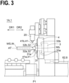
- FIGs. 1 to 7 are side views of the laser-beam working machine 1A according to the first embodiment, schematically illustrating the laser-beam working machine 1A.
- the laser-beam working machine 1A includes a laser head 20, a first chuck 3, a second chuck 4, and a mover 6.
- the laser head 20 machines the workpiece W by irradiating the workpiece W extending in the first direction DR1 with a laser beam LA.
- the laser head 20 may cut the workpiece W by irradiating the workpiece W with the laser beam LA, or may form a hole in the workpiece W by irradiating the workpiece W with the laser beam LA.
- the workpiece W is a long workpiece WL.
- the laser head 20 by cutting the long workpiece WL with a laser beam, the laser head 20 is capable of producing a machined product Wt and a short workpiece WS from the long workpiece WL.
- the short workpiece WS is produced by laser-beam machining of the long workpiece WL.
- only a grip member 31 of the first chuck 3 is capable of supporting the short workpiece WS.
- the long workpiece WL and the short workpiece WS will be hereinafter collectively referred to as "workpiece W”.
- workpiece W the workpiece that can be supported only by the grip member 31 of the first chuck 3
- short workpiece WS the workpiece that can be supported only by the grip member 31 of the first chuck 3
- the first chuck 3 includes the grip member 31 for holding the workpiece W.
- the first chuck 3 is movable together with the workpiece W in the first direction DR1.
- the second chuck 4 is provided between the laser head 20 and the first chuck 3 in a direction along the first direction DR1. More specifically, the second chuck 4 is provided on the first direction DR1 side relative to the first chuck 3, and the laser head 20 is provided on the first direction DR1 side relative to the second chuck 4.
- the second chuck 4 includes a plurality of guide rollers 41, which interpose the workpiece W.
- the plurality of guide rollers 41 guide the movement of the workpiece W (more specifically, the long workpiece WL) in either the first direction DR1 or the second direction DR2.
- each of the plurality of guide rollers 41 is rotatable about a rotation axis AX, which is perpendicular to the first direction DR1.
- the plurality of guide rollers 41 are provided so as to interpose the workpiece W (more specifically, the long workpiece WL).
- the plurality of guide rollers 41 include: a first guide roller 41a to be in contact with the workpiece W (more specifically, the long workpiece WL); and a second guide roller 41b to be in contact with the workpiece W (more specifically, the long workpiece WL).
- the second guide roller 41b is provided on a side opposite to the first guide roller 41a with respect to the workpiece W.
- the mover 6 moves the first chuck 3 in either the first direction DR1 or the second direction DR2 . As illustrated in FIGs. 2 and 3 , the mover 6 moves the first chuck 3 in the first direction DR1 so that an end face 31e of the grip member 31 moves between the plurality of guide rollers 41 and approaches the laser head 20. In other words, the mover 6 moves the first chuck 3 in the first direction DR1, thereby moving a tip end portion of the grip member 31 (more specifically, the end face 31e on the first direction DR1 side of the grip member 31) of the first chuck 3 to a first position P1 (see FIG. 3 ) on the first direction DR1 side relative to the plurality of guide rollers 41 from a second position P2 (see FIG. 2 ) on the second direction DR2 side relative to the plurality of guide rollers 41.
- the position of the end face 31e of the grip member 31 of the first chuck 3 is changeable to the first position P1 (see FIG. 3 ) on the first direction DR1 side relative to the plurality of guide rollers 41 from the second position P2 (see FIG. 2 ) on the second direction DR2 side relative to the plurality of guide rollers 41.
- the base end portion Wb of the workpiece W (more specifically, the short workpiece WS) held by the grip member 31 can be made closer to the laser head 20. In this manner, the length of a remaining workpiece Wr (see FIG. 4 ) produced by machining of the workpiece W extending in the first direction DR1 can be shortened.
- the length of the remaining workpiece Wr is shortened, the amount of unused material is reduced, and the load on the environment is reduced.
- the "remaining workpiece Wr” means an end material produced by the laser-beam machining of the workpiece W.
- the mover 6 includes: a drive 61 (more specifically, a motor such as a servo motor), which moves the first chuck 3 in either the first direction DR1 or the second direction DR2 ; and a guide member 62 (for example, a guide rail) for guiding the movement of the first chuck 3 in either the first direction DR1 or the second direction DR2 .
- the mover 6 may include a power transmission member 63 (for example, a ball screw) for converting the power of the drive 61 into the movement of the first chuck 3. It is to be noted that in a case where the drive 61 is a linear motor, the ball screw can be omitted.
- the mover 6 may also convert the rotational force of the drive 61 into the movement of the first chuck 3 in either the first direction DR1 or the second direction DR2 via a rack and pinion.
- the drive 61 (more specifically, a motor) is provided in a first base 91.
- the drive 61 (more specifically, the motor) may be provided in the first chuck 3.
- the first chuck 3 may be self-propelled.
- the laser-beam working machine 1A (more specifically, the second chuck 4) includes a roller mover 43, which moves the plurality of guide rollers 41.
- the roller mover 43 moves the plurality of guide rollers 41 in a direction not parallel to the first direction DR1 (in other words, a direction different from the first direction DR1 and the second direction DR2 ), between advanced positions (A1, A2) in contact with the workpiece W (more specifically, the long workpiece WL) and retracted positions (B1, B2) that allow the end face 31e of the grip member 31 to pass through the plurality of guide rollers 41 (see FIG. 7 ).
- the roller mover 43 moves the plurality of guide rollers 41 between the advanced positions (A1, A2) in contact with the workpiece W (more specifically, the long workpiece WL) and the retracted positions (B1, B2) in which the distance between each of the plurality of guide rollers 41 and a first axis AT is longer than the distance between each of the plurality of guide rollers 41 in the advanced positions (A1, A2) and the first axis AT, and which thus allows the end face 31e of the grip member 31 to pass through the plurality of guide rollers 41.
- the above-described first axis AT is an axis coincident with the rotation axis of the grip member 31 (in other words, the rotation axis of the workpiece W held by the grip member 31) to be rotated by a first rotation drive 36 as will be described later.
- the above-described first axis AT is an axis coincident with the rotation axis of the plurality of guide rollers 41 (in other words, the rotation axis of the workpiece W, which is interposed by the plurality of guide rollers 41) to be rotated by a second rotation drive 46 as will be described later.
- the roller mover 43 includes a first roller mover 43a, which moves the first guide roller 41a between a first advanced position A1 and a first retracted position B1.
- the roller mover 43 also includes a second roller mover 43b, which moves a second guide roller 41b between a second advanced position A2 and a second retracted position B2.
- the power source for example, an actuator or a motor
- the power source with which the second roller mover 43b moves the second guide roller 41b may be identical to or different from the power source (for example, an actuator or a motor) with which the first roller mover 43a moves the first guide roller 41a.
- the workpiece W (more specifically, the long workpiece WL) is supported in a stable manner by the grip member 31 and the plurality of guide rollers 41.
- FIG. 7 in a case where the plurality of guide rollers 41 are in the retracted positions (B1, B2), interference between the grip member 31, which moves in the first direction DR1, and the plurality of guide rollers 41 is avoided.
- the plurality of guide rollers 41 includes the first guide roller 41a and the second guide roller 41b.
- the plurality of guide rollers 41 are arranged in the vicinity of the laser head 20, and are capable of supporting a tip end part of the long workpiece WL or a central part of the long workpiece WL.
- any magnitude is applicable, as long as it is possible to guide the movement of the workpiece W in either the first direction DR1 or the second direction DR2 .
- Such holding force may be substantially zero.
- the first guide roller 41a is supported to be rotatable about a first rotation axis AX1 by a first roller support member 42a, which is included in the second chuck 4.
- the first rotation axis AX1 is perpendicular to the first direction DR1.
- the second guide roller 41b is rotatably supported about a second rotation axis AX2 by a second roller support member 42b, which is included in the second chuck 4.
- the second rotation axis AX2 is perpendicular to the first direction DR1.
- the second rotation axis AX2 is parallel to the first rotation axis AX1.
- the grip member 31 in a state in which the grip member 31 is inserted on inner sides of the plurality of guide rollers 41 (more specifically, in a state in which the grip member 31 is partially provided in an inner region SP, which is defined by the plurality of guide rollers 41), the grip member 31 is rotatable about the first axis AT (see an arrow R2).
- the posture of the workpiece W (more specifically, the short workpiece WS) about the first axis AT is changeable.
- the first axis AT is an axis parallel to the first direction DR1.
- the plurality of guide rollers 41 are rotatable about the first axis AT together with the grip member 31.
- the first chuck 3 includes a first rotation drive 36, which rotates the grip member 31 about the first axis AT, which is parallel to the first direction DR1.
- the first rotation drive 36 rotates the grip member 31 and a first rotor 35, which supports the grip member 31, about the first axis AT.
- the first rotation drive 36 is capable of rotating the grip member 31 about the first axis AT, in the state in which the grip member 31 is inserted on the inner sides of the plurality of guide rollers 41.
- the second chuck 4 includes a second rotation drive 46, which rotates the plurality of guide rollers 41 about the first axis AT, which is parallel to the first direction DR1.
- the second rotation drive 46 rotates the plurality of guide rollers 41 and a second rotor 45, which supports the plurality of guide rollers 41, about the first axis AT.
- the second rotation drive 46 is capable of rotating the plurality of guide rollers 41 about the first axis AT, in the state in which the grip member 31 is inserted on the inner sides of the plurality of guide rollers 41.
- the long workpiece WL which is supported by both the first chuck 3 and the second chuck 4, is made rotatable about the first axis AT in a stable manner.
- the plurality of guide rollers 41 and the grip member 31 are made rotatable about the first axis AT in a smooth manner, in the state in which the grip member 31 is inserted on the inner sides of the plurality of guide rollers 41 (see FIG. 7 ).
- only one of the first rotor 35 and the second rotor 45 may be driven to actively rotate about the first axis AT by the rotation drive, and the other one of the first rotor 35 and the second rotor 45 may passively rotate about the first axis AT.
- the other one of the first rotor 35 and the second rotor 45 is supported by a support member so as to be freely rotatable about the first axis AT via a bearing.
- the grip member 31 is capable of holding the workpiece W (more specifically, the base end portion Wb of the workpiece W).
- the grip member 31 includes: a first gripper 32a to be in contact with the workpiece W; and a second gripper 32b to be in contact with the workpiece W.
- the second gripper 32b is provided on a side opposite to the first gripper 32a with respect to the workpiece W.
- the grip member 31 includes: a first gripper support body 33a, which supports the first gripper 32a; and a second gripper support body 33b, which supports the second gripper 32b.
- the grip member 31 in the state in which the grip member 31 is inserted on the inner sides of the plurality of guide rollers 41, the grip member 31 is capable of releasing holding the workpiece W (for example, holding the remaining workpiece Wr produced by the laser-beam machining of the workpiece W). More specifically, as illustrated in FIGs. 4 and 5 , in the state in which the grip member 31 is inserted on the inner sides of the plurality of guide rollers 41, the first gripper 32a and the second gripper 32b are respectively capable of retracting in the directions away from the first axis AT (more specifically, in directions respectively from the first axis AT toward the plurality of guide rollers 41).
- the laser-beam working machine 1A (more specifically, the first chuck 3) includes a gripper mover 34, which moves the plurality of grippers 32 including the first gripper 32a and the second gripper 32b between holding positions (A3, A4) in contact with the workpiece (more specifically, the remaining workpiece Wr of the workpiece) and release positions (B3, B4) spaced apart from the workpiece (more specifically, the remaining workpiece Wr of the workpiece).
- the gripper mover 34 includes: a first gripper mover 34a, which moves the first gripper 32a between a first holding position A3 and a first release position B3; and the second gripper mover 34b, which moves the second gripper 32b between a second holding position A4 and a second release position B4.
- the power source for example, an actuator or a motor
- the power source with which the second gripper mover 34b moves the second gripper 32b may be identical to or different from the power source (for example, an actuator or a motor) with which the first gripper mover 34a moves the first gripper 32a.
- the gripper mover 34 moves the plurality of grippers 32, which include the first gripper 32a and the second gripper 32b, from the holding positions (A3, A4) in contact with the remaining workpiece Wr of the workpiece to the release positions (B3, B4) respectively toward the plurality of guide rollers 41.
- the remaining workpiece Wr is released from the grip member 31, and the remaining workpiece Wr drops onto the first direction DR1 side relative to the plurality of guide rollers 41 (see an arrow D1 in FIG. 5 ). Therefore, a pusher for pushing out the remaining workpiece Wr from the grip member 31 to the first direction DR1 side can be omitted.
- the pusher and the operation of the pusher are omitted, and thus the time needed for unloading the remaining workpiece Wr can be shortened.
- the workpiece is, for example, a pipe Wp, which extends in the first direction DR1.
- the short workpiece WS (see FIG. 2 ) is a short pipe that is produced by the laser-beam machining of the pipe Wp and that can be supported only by the grip member 31.
- the cross-sectional shape of the pipe Wp in a direction perpendicular to the first direction DR1 may be rectangular, circular, or triangular.
- the workpiece W may also be a workpiece other than the pipe.
- the workpiece W may be a long workpiece having a letter C-shaped cross-section, a long workpiece having a letter H-shaped cross-section, or a long workpiece having a letter L-shaped cross-section.
- FIG. 8 is a side view of the laser-beam working machine 1B according to the second embodiment, schematically illustrating the laser-beam working machine 1B.
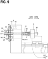
- FIGs. 9 and 10 are side views of the laser-beam working machine 1B according to the second embodiment, each illustrating an enlarged part of the laser-beam working machine 1B.
- FIG. 11 is a cross-sectional view taken along the arrow E-E in FIG. 8 .
- FIG. 12 is a front view of the second chuck 4, schematically illustrating the second chuck as an example.
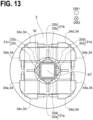
- FIG. 13 is a cross-sectional view taken along the arrow F-F in FIG. 8 .
- FIG. 14 to 17 are cross-sectional views of a grip member 31 and a plurality of guide rollers 41, each schematically illustrating the state in which the grip member 31 is inserted on the inner sides of the plurality of guide rollers 41.
- FIG. 14 is a cross-sectional view on a plane parallel to the first axis AT
- FIGs. 15 to 17 are each a cross-sectional view on a plane perpendicular to a first axis AT and passing through a third guide roller 41c and a fourth guide roller 41d.
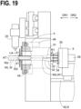
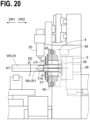
- FIGs. 18 to 20 are each a side view of the laser-beam working machine 1B according to the second embodiment, schematically illustrating an enlarged part of the laser-beam working machine 1B.
- FIG. 14 is a cross-sectional view on a plane parallel to the first axis AT
- FIGs. 15 to 17 are each a cross-sectional view on a plane perpendicular to a first axis AT and passing through a third guide roller 41c and
- FIG. 21 is a functional block diagram of a controller 8 and a plurality of devices to be controlled by the controller 8, schematically illustrating the controller and the plurality of devices.
- FIG. 22 is a block diagram of the controller 8, schematically illustrating a hardware configuration of the controller.
- FIG. 23 schematically illustrates a state in which the rotation phases of a plurality of grippers 32 are coincident with the rotation phases of the plurality of guide rollers 41.
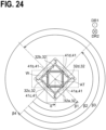
- FIG. 24 schematically illustrates a state in which the rotation phases of the plurality of grippers 32 and the rotation phases of the plurality of guide rollers 41 are shifted from each other by 45 degrees.
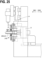
- FIG. 25 is a side view of the laser-beam working machine 1B according to the second embodiment, schematically illustrating the enlarged part of the laser-beam working machine 1B. It is to be noted that in FIGs. 8 to 10 , 18 to 20 , and 25 , in order to make an inner state of the second chuck 4 recognizable, the second chuck 4 is partially cut out, and a cross-sectional view of such a cut out part is illustrated.
- the laser-beam working machine 1B includes: a laser head 20; a first chuck 3; a second chuck 4; and a mover 6.
- the laser head 20 machines the workpiece W.
- the first chuck 3 includes a grip member 31 for holding the workpiece W, and is movable together with the workpiece W in the first direction DR1.
- the second chuck 4 is provided between the laser head 20 and the first chuck 3 in a direction along the first direction DR1.
- the second chuck 4 includes a plurality of guide rollers 41. The plurality of guide rollers 41 interpose the workpiece W, and guide the movement of the workpiece W in the first direction DR1. As illustrated in FIG.
- the mover 6 is capable of moving the first chuck 3 in the first direction DR1 so that an end face 31e of the grip member 31 moves among the plurality of guide rollers 41 and approaches the laser head 20.
- the mover 6 is capable of moving the position of the end face 31e on the first direction DR1 side of the grip member 31 to a first position P1 on the first direction DR1 side relative to the plurality of guide rollers 41 from a second position P2 on the second direction DR2 side relative to the plurality of guide rollers 41.
- the second embodiment has effects similar to those in the first embodiment.
- FIG. 11 is a cross-sectional view taken along the arrow E-E in FIG. 8 .
- the second chuck 4 includes a plurality of guide rollers 41, which includes a first guide roller 41a and a second guide roller 41b.
- the second chuck 4 may include the first guide roller 41a, the second guide roller 41b, a third guide roller 41c, and a fourth guide roller 41d.
- the positions of the third guide roller 41c and the fourth guide roller 41d in directions along the first direction DR1 are slightly different from the positions of the first guide roller 41a and the second guide roller 41b in the directions along the first direction DR1.
- the third guide roller 41c is movable to a position partially overlapping the first guide roller 41a and the second guide roller 41b.
- the fourth guide roller 41d is movable to a position partially overlapping the first guide roller 41a and the second guide roller 41b.
- the second chuck 4 includes a plurality of roller support members 42, which respectively support the plurality of guide rollers 41.
- Each of the plurality of roller support members 42 is, for example, a plate-shaped body.
- the second chuck 4 includes: a first roller support member 42a, which supports the first guide roller 41a to be rotatable about the first rotation axis AX1; a second roller support member 42b, which supports the second guide roller 41b to be rotatable about the second rotation axis AX2, and a third roller support member 42c, which supports the third guide roller 41c to be rotatable about a third rotation axis AX3; and a fourth roller support member 42d, which supports the fourth guide roller 41d to be rotatable about a fourth rotation axis AX4.
- the first rotation axis AX1 is perpendicular to the first direction DR1
- the second rotation axis AX2 is parallel to the first rotation axis AX1.
- the third rotation axis AX3 is perpendicular to both the first direction DR1 and the first rotation axis AX1
- the fourth rotation axis AX4 is parallel to the third rotation axis AX3.
- a rectangular inner region SP1 is defined by the plurality of guide rollers 41. More specifically, when viewed in the direction along the second direction DR2 , the rectangular inner region SP1 is defined by the first guide roller 41a, the second guide roller 41b, the third guide roller 41c, and the fourth guide roller 41d.
- the plurality of guide rollers 41 are capable of defining the rectangular inner region SP1
- the plurality of guide rollers 41 are capable of guiding the workpiece W having a rectangular cross-section (for example, a square cross-section, a rectangular cross-section) in a stable manner.
- the plurality of guide rollers 41 are also capable of guiding the workpiece W having any cross-sectional shape other than the rectangular one (for example, a circular cross-sectional shape, a letter C-shaped cross-sectional shape, a letter H-shaped cross-sectional shape, and the like).
- the laser-beam working machine 1B (more specifically, the second chuck 4) includes a roller mover 43, which moves the plurality of guide rollers 41.
- the roller mover 43 moves the plurality of guide rollers 41 in a direction not parallel to the first direction DR1 (for example, a direction perpendicular to the first direction DR1 ) between the advanced positions in contact with the workpiece W and the retracted positions (see FIG. 12 ) that allow the end face 31e of the grip member 31 to move among the plurality of guide rollers 41.
- a direction from the first guide roller 41a toward the second guide roller 41b is defined as a third direction DR3
- a direction from the second guide roller 41b toward the first guide roller 41a is defined as a fourth direction DR4.
- the third direction DR 3 and the fourth direction DR4 are each perpendicular to the first direction DR1, for example.
- the roller mover 43 includes a first roller mover 43a (for example, an actuator or a motor), which moves the first guide roller 41a in the third direction DR3 (or the fourth direction DR4).
- the first roller mover 43a is preferably capable of fixing the position of the first guide roller 41a at any position within the first range.
- the roller mover 43 includes a second roller mover 43b (for example, an actuator or a motor), which moves the second guide roller 41b in the fourth direction DR4 (or the third direction DR3).
- the second roller mover 43b is preferably capable of fixing the position of the second guide roller 41b at any position within the second range.
- the power source (for example, an actuator or a motor) with which the second roller mover 43b moves the second guide roller 41b may be identical to or different from the power source (for example, an actuator or a motor) with which the first roller mover 43a moves the first guide roller 41a.
- a direction from the third guide roller 41c toward the fourth guide roller 41d is defined as a fifth direction DR5
- a direction from the fourth guide roller 41d toward the third guide roller 41c is defined as a sixth direction DR6.
- the fifth direction DR5 and the sixth direction DR6 are each perpendicular to the first direction DR1, for example.
- the roller mover 43 includes a third roller mover 43c, which moves the third guide roller 41c in the fifth direction DR5 (or the sixth direction DR6).
- the third roller mover 43c is preferably capable of fixing the position of the third guide roller 41c at any position within the third range.
- the roller mover 43 includes a fourth roller mover 43d, which moves the fourth guide roller 41d to the sixth direction DR6 (or the fifth direction DR5).
- the roller mover 43 is preferably capable of fixing the position of the fourth guide roller 41d at any position within the fourth range.
- the power source (for example, an actuator or a motor) with which the fourth roller mover 43d moves the fourth guide roller 41d may be identical to or different from the power source (for example, an actuator or a motor) with which the third roller mover 43c moves the third guide roller 41c.
- the second chuck 4 includes a second rotor 45 and a second rotation drive 46 (for example, a second motor of a second servo motor or the like).
- the second rotor 45 supports the plurality of guide rollers 41, a plurality of roller support members 42, which respectively support the plurality of guide rollers 41, and the roller mover 43, which moves the plurality of guide rollers 41.
- the second rotor 45 has an annular body.
- the second rotor 45 includes a through hole 45h into which the grip member 31 of the first chuck 3 is inserted.
- the through hole 45h is a hole that allows the end face 31e of the grip member 31 of the first chuck 3 to pass through.
- the second rotation drive 46 rotates the second rotor 45 about the first axis AT.
- the second rotation drive 46 rotates the second rotor 45, thereby rotating the plurality of guide rollers 41, the plurality of roller support members 42, the roller mover 43, and the second rotor 45 integrally about the first axis AT.
- the second chuck 4 may include a power transmission member 47, such as a gear, for transmitting driving force of the second rotation drive 46 to the second rotor 45.
- the drive axis of the second rotation drive 46 does not have to be coaxial with the first axis AT.
- FIG. 13 is a cross-sectional view taken along the arrow F-F in FIG. 8 .
- the grip member 31 includes: a first grip member 31a to be in contact with the workpiece W; and a second grip member 31b to be in contact with the workpiece W.
- the second grip member 31b is provided on a side opposite to the first grip member 31a with respect to the workpiece W.
- the first grip member 31a includes: a first gripper 32a, and a first gripper support body 33a, which supports the first gripper 32a.
- the second grip member 31b includes: a second gripper 32b; and a second gripper support body 33b, which supports the second gripper 32b.
- the grip member 31 may include: a third grip member 31c to be in contact with the workpiece W; and a fourth grip member 31d, which is provided on a side opposite to the third grip member 31c with respect to the workpiece, and which is to be in contact with the workpiece W.
- the third grip member 31c includes: a third gripper 32c; and a third gripper support body 33c, which supports the third gripper 32c.
- the fourth grip member 31d includes: a fourth gripper 32d; and a fourth gripper support body 33d, which supports the fourth gripper 32d.
- the angle made by a direction from the third grip member 31c toward the fourth grip member 31d and a direction from the first grip member 31a toward the second grip member 31b is 90 degrees.
- the grip member 31 is rotatable about the first axis AT (see an arrow R2), in a state in which the grip member 31 is inserted on inner sides of the plurality of guide rollers 41, in other words, in a state in which the grip member 31 is partially arranged in an inner region SP, which is defined by the plurality of guide rollers 41 (see the inner region SP surrounded by a dashed line).
- the posture of the workpiece W (more specifically, the short workpiece WS) about the first axis AT is changeable.
- FIG. 15 is a cross-sectional view taken along the arrow G-G in FIG. 14 .
- the plurality of guide rollers 41 are rotatable about the first axis AT together with the grip member 31 (see an arrow R2).
- the grip member 31 in order to rotate the grip member 31 about the first axis AT, there is no need to additionally retract the plurality of guide rollers 41 respectively in directions away from the first axis AT.
- the grip member 31 includes a plurality of grippers 32.
- the plurality of grippers 32 are respectively arrangeable in a plurality of corner portions C of the rectangular inner region SP1, which is defined by the plurality of guide rollers 41.
- the plurality of guide rollers 41 are respectively retracted by small distances in the directions away from the first axis AT, and then the plurality of grippers 32 are respectively insertable on the inner sides of the plurality of guide rollers 41.
- the first gripper 32a is provided in a first corner portion C1 of the above-described rectangular inner region SP1
- the second gripper 32b is provided in a second corner portion C2 of the above-described rectangular inner region SP1
- the third gripper 32c is provided in a third corner portion C3 of the above-described rectangular inner region SP1
- the fourth gripper 32d is provided in a fourth corner portion C4 of the above-described rectangular inner region SP1.
- an outer side surface 320u of each of the plurality of grippers 32 When viewed in a direction along the first direction DR1 (or the second direction DR2 ), an outer side surface 320u of each of the plurality of grippers 32 preferably has a shape complementary to the corner portion C having a right angle. In this case, each of the plurality of grippers 32 can be suitably provided in the corner portion C having a right angle in the rectangular inner region SP1. In addition, an inner side surface 320n of each of the plurality of grippers 32 is preferably a planar surface. In this case, the workpiece W is held by the plurality of grippers 32 in a stable manner. As illustrated in FIG. 16 , when viewed in a direction along the second direction DR2 , each of the plurality of grippers 32 may have a substantially right-angled triangular shape.
- the grip member 31 in a state in which the grip member 31 is inserted on the inner sides of the plurality of guide rollers 41, the grip member 31 is capable of releasing holding the workpiece W (for example, holding the remaining workpiece Wr, which is produced by the laser-beam machining of the workpiece W). More specifically, in a state in which the grip members 31 is provided on the inner sides of the plurality of guide rollers 41, the plurality of grippers 32 are respectively retractable in the directions away from the first axis AT (more specifically, in directions toward the plurality of guide rollers 41 from the first axis AT).
- the laser-beam working machine 1B (more specifically, the first chuck 3) includes a gripper mover 34, which moves the plurality of grippers 32.
- the gripper mover 34 moves the plurality of grippers 32 in a direction not parallel to the first direction DR1 (for example, a direction perpendicular to the first direction DR1 ) between holding positions in contact with the workpiece W and release positions (if necessary, see FIG. 17 ) spaced apart from the workpiece W (more specifically, the remaining workpiece Wr).
- the gripper mover 34 includes a first gripper mover 34a (for example, an actuator or a motor), which moves the first gripper 32a in a direction approaching the second gripper 32b (or a direction away from the second gripper 32b).
- the gripper mover 34 also includes a second gripper mover 34b (for example, an actuator or a motor), which moves the second gripper 32b in a direction approaching the first gripper 32a (or a direction away from the first gripper 32a).
- the power source (for example, an actuator or a motor) with which the second gripper mover 34b moves the second gripper 32b may be identical to or different from the power source (for example, an actuator or a motor) with which the first gripper mover 34a moves the first gripper 32a.
- the gripper mover 34 includes a third gripper mover 34c (for example, an actuator or a motor), which moves the third gripper 32c in a direction approaching the fourth gripper 32d (or a direction away from the fourth gripper 32d).
- the gripper mover 34 also includes a fourth gripper mover 34d (for example, an actuator or a motor), which moves the fourth gripper 32d in a direction approaching the third gripper 32c (or a direction away from the third gripper 32c).
- the power source (for example, an actuator or a motor) with which the fourth gripper mover 34d moves the fourth gripper 32d may be identical to or different from the power source (for example, an actuator or a motor) with which the third gripper mover 34c moves the third gripper 32c.
- the first chuck 3 includes: a first rotor 35; and a first rotation drive 36 (for example, a first motor such as a first servo motor).
- the first rotor 35 supports the plurality of grippers 32, the plurality of gripper support bodies 33, and the gripper mover 34.
- the first rotation drive 36 rotates the first rotor 35 about the first axis AT.
- the first rotation drive 36 rotates the first rotor 35, thereby rotating the plurality of grippers 32, the plurality of gripper support bodies 33, and the gripper mover 34 integrally about the first axis AT.
- the drive axis of the first rotation drive 36 is coaxial with the first axis AT.
- the laser-beam working machine 1B includes two rotation drives (36, 46).
- the long workpiece WL which is supported by both the first chuck 3 and the second chuck 4, is made rotatable about the first axis AT in a stable manner.
- the plurality of guide rollers 41 and the grip member 31 are made rotatable about the first axis AT in a smooth manner, in the state in which the grip member 31 is inserted on the inner sides of the plurality of guide rollers 41 (see FIG. 20 ).
- the plurality of guide rollers 41 and the grip member 31 are made rotatable about the first axis AT in a smooth manner, in the state in which the grip member 31 is inserted on the inner sides of the plurality of guide rollers 41 (see FIG. 20 ).
- the first rotation drive 36 is capable of rotating the grip member 31 about the first axis AT, in the state in which the grip member 31 is inserted on the inner sides of the plurality of guide rollers 41
- the second rotation drive 46 is capable of rotating the plurality of guide rollers 41 about the first axis AT, in the state in which the grip member 31 is inserted on the inner sides of the plurality of guide rollers 41.
- only one of the first rotor 35 and the second rotor 45 may be driven to actively rotate about the first axis AT by the rotation drive, and the other one of the first rotor 35 and the second rotor 45 may passively rotate about the first axis AT.
- the mover 6 is capable of moving the first chuck 3 in the first direction DR1, and is capable of moving the first chuck 3 in the second direction DR2.
- the mover 6 includes: a drive 61 (more specifically, a motor such as a servo motor), which moves the first chuck 3; and a guide member 62 (for example, a guide rail), which guides the movement of the first chuck 3.
- the mover 6 may include a power transmission member that converts the power of the drive 61 into the movement of the first chuck 3.
- the mover 6 may also convert the rotational force of the drive 61 into the movement of the first chuck 3 in either the first direction DR1 or the second direction DR2 via a rack and pinion.
- the laser-beam working machine 1B includes loaders 71.
- the loader 71 loads the workpiece W into the laser-beam working machine 1B. More specifically, the loader 71 loads the workpiece W into between the first chuck 3 and the second chuck 4. The workpiece W that has been loaded is held by the grip member 31 of the first chuck 3.
- the laser-beam working machine 1B includes at least one first support member 72, which supports the workpiece W separately from the first chuck 3 and the second chuck 4.
- the first support member 72 is provided on the second direction DR2 side relative to the second chuck 4.
- the first support members 72 are provided between the first chuck 3 and the second chuck 4.
- the first support member 72 is configured to support the lower surface of the workpiece W, when the workpiece W moves in the first direction DR1 (or when the workpiece W is machined by the laser beam irradiated from the laser head 20). In this case, deflection of the workpiece W (more specifically, the long workpiece WL) is eliminated or minimized, while the workpiece W is moving or while the workpiece W is being machined.
- the first support member 72 may be provided on the loader 71, or may be provided on the first base 91 of the laser-beam working machine 1B.
- the laser-beam working machine 1B may include a support member mover 73, which moves the first support member 72 between an advanced position at which the support member mover 73 is capable of supporting the workpiece W and a retracted position outside the moving path of the first chuck 3.
- the support member mover 73 moves the first support member 72 to the retracted position, and thus interference between the first chuck 3, which moves in the first direction DR1, and the first support member 72 is prevented.
- the laser-beam working machine 1B includes unloaders 75.
- the unloader 75 unloads the machined product produced by the laser-beam machining from a workpiece machining region MR of the laser-beam working machine 1B to the outside of the workpiece machining region MR. More specifically, the unloader 75 receives the workpiece W that has been machined by the laser beam irradiated from the laser head 20, and then unloads the workpiece W from the workpiece machining region MR to the outside of the workpiece machining region.
- the laser-beam working machine 1B includes at least one second support member 76, which supports the workpiece W separately from the first chuck 3 and the second chuck 4.
- the second support member 76 is provided on the first direction DR1 side relative to the second chuck 4.
- the second support member 76 is configured to support the lower surface of the workpiece W, when the workpiece W moves in the first direction DR1 (or when the workpiece W is machined with a laser beam irradiated from the laser head 20). In this case, the deflection of the workpiece W (more specifically, the long workpiece WL) is eliminated or minimized, while the workpiece W is moving or while the workpiece W is being machined.
- the second support member 76 may be provided on the unloader 75.
- the laser-beam working machine 1B includes a remaining workpiece collector 77.
- the remaining workpiece collector 77 collects the remaining workpiece Wr, which has been produced by machining of the workpiece W.
- the remaining workpiece collector 77 is provided directly below the workpiece machining region MR.
- the remaining workpiece collector 77 may include: a carriage 78; and a remaining workpiece container 79, which is attached to the carriage 78.
- the first chuck 3 includes: the grip member 31; the first rotor 35, which supports the grip member 31; a rotor support member 37, which supports the first rotor 35 to be rotatable about the first axis AT; the first rotation drive 36, which rotates the first rotor 35 about the first axis AT; and a first chuck base 38, which supports the rotor support member 37.
- the first rotation drive 36 is attached to the rotor support member 37.
- the first chuck base 38 is slidably movable in either the first direction DR1 or the second direction DR2 along the guide member 62, which is provided on the first base 91 of the laser-beam working machine 1B.
- the second chuck 4 includes: the plurality of guide rollers 41; the second rotor 45, which supports the plurality of guide rollers 41 via the roller support members 42; a second rotor support member 48, which supports the second rotor 45 to be rotatable about the first axis AT; and the second rotation drive 46, which rotates the second rotor 45 about the first axis AT.
- the second rotation drive 46 is attached to the second rotor support member 48.
- the second rotor support member 48 has an annular body.
- the second rotor support member 48 includes a through hole 48h, into which the grip member 31 of the first chuck 3 is inserted.
- the second rotor support member 48 prohibits the first chuck base 38 of the first chuck 3 from moving in the first direction DR1 beyond the second rotor support member 48.
- the first chuck base 38 of the first chuck 3 is not capable of passing through the through hole 48h of the second rotor support member 48.
- the second chuck 4 is fixed onto the second base 92 of the laser-beam working machine 1B.
- the second chuck 4 may be movable relatively to the second base 92 or the first base 91 in either the first direction DR1 or the second direction DR2 .
- the laser-beam working machine 1B includes a laser-beam irradiation apparatus 2, and the laser-beam irradiation apparatus 2 includes: the laser head 20, the laser head mover 22, which moves the laser head 20; and a third base 24, which supports the laser head 20 via the laser head mover 22.
- the laser head mover 22 moves the laser head 20.
- the laser head mover 22 includes: a vertical drive 22a, which moves the laser head 20 along a vertical direction; and a horizontal drive 22b, which moves the laser head 20 along a horizontal direction.
- the laser head mover 22 may include a tilt device for tilting the laser head 20 about a horizontal axis.
- the laser head mover 22 is a device for moving the laser head 20 two-dimensionally on YZ plane.
- the laser head mover 22 may be a device for moving the laser head 20 three-dimensionally.
- the laser head mover 22 may be capable of moving the laser head 20 in X direction, capable of moving the laser head 20 in Y direction, and capable of moving the laser head 20 in Z direction.
- Z direction is a direction parallel to the vertical direction
- X direction is a direction parallel to the first direction DR1
- Y direction is a direction perpendicular to both X direction and Z direction.
- the third base 24 is fixed onto the second base 92.
- the third base 24 may be directly fixed onto the first base 91 of the laser-beam working machine 1B.
- the laser-beam working machine 1B includes the controller 8.
- the controller 8 may include one computer, or may include a plurality of computers.
- FIG. 22 is a block diagram illustrating a hardware configuration of the controller 8, as an example.
- the controller 8 includes: a processor 80; a memory 82; a communication circuit 84; and an input device 86 (for example, a display 862 with a touch panel (see FIG. 21 )).
- the processor 80, the memory 82, the communication circuit 84, and the input device 86 are connected with one another via a bus 88.
- Data necessary for the laser-beam machining may be input into the controller 8 via the input device 86, or may be input from another computer into the controller 8 via the communication circuit 84.
- the input device 86 is not limited to the display 862 with the touch panel.
- the controller 8 may include: the input device 86 such as a button, a switch, a lever, a pointing device, or a keyboard; and a display for displaying data that has been input into the input device 86 or other information.
- the processor 80 executes a machining program 822, which is stored in the memory 82, based on the data that has been input into the controller 8, and generates a control signal.
- the communication circuit 84 transmits such a control signal to devices to be controlled (more specifically, the mover 6, the first chuck 3, the second chuck 4, the laser head 20, the laser head mover 22, and the like).
- the processor 80 executes the machining program 822, and then the controller 8 is capable of controlling the mover 6, the first chuck 3, the second chuck 4, the laser head 20, and the laser head mover 22.
- the machining program 822 may include a first program for performing a first moving mode to be described below, may include a second program for performing a second moving mode to be described below, may include a third program for performing a first rotating mode to be described below, may include a fourth program for performing a second rotating mode to be described below, may include a fifth program for performing a long workpiece machining mode to be described below, may include a sixth program for performing a short workpiece machining mode to be described below, and may include a seventh program for performing a remaining workpiece discharging mode to be described below.
- the controller 8 controls the mover 6, the first rotation drive 36 of the first chuck 3, the gripper mover 34 of the first chuck 3, the second rotation drive 46 of the second chuck 4, the roller mover 43 of the second chuck 4, the laser head 20, and the laser head mover 22.
- the controller 8 transmits a first control signal S1 to the mover 6, and the mover 6, which receives the first control signal S1, moves the first chuck 3 in either the first direction DR1 or the second direction DR2.
- the controller 8 transmits a second control signal S2 to the first rotation drive 36, and the first rotation drive 36, which receives the second control signal S2, rotates the grip member 31 (more specifically, the first rotor 35, which supports the grip member 31) about the first axis AT.
- the controller 8 transmits a third control signal S3 to the gripper mover 34, and the gripper mover 34, which receives the third control signal S3, moves the plurality of grippers 32 respectively (more specifically, the plurality of gripper support bodies 33, which respectively support the plurality of grippers 32) in the directions away from the first axis AT or directions approaching the first axis AT.
- the controller 8 transmits a fourth control signal S4 to the second rotation drive 46, and the second rotation drive 46, which receives the fourth control signal S4, rotates the plurality of guide rollers 41 (more specifically, the second rotor 45, which supports the plurality of guide rollers 41) about the first axis AT.
- the controller 8 transmits a fifth control signal S5 to the roller mover 43, and the roller mover 43, which receives the fifth control signal S5, moves the plurality of guide rollers 41 respectively (more specifically, the plurality of roller support members 42, which respectively support the plurality of guide rollers 41) in either the directions away from the first axis AT or directions approaching the first axis AT.
- the controller 8 transmits a sixth control signal S6 to the laser head 20, and the laser head 20, which receives the sixth control signal S6, irradiates the workpiece W with a laser beam.
- the controller 8 also transmits a seventh control signal S7 to the laser head mover 22, and the laser head mover 22, which receives the seventh control signal S7, moves the laser head 20.
- the controller 8 By controlling the mover 6, the first rotation drive 36, and the second rotation drive 46, the controller 8 is capable of performing the first moving mode.
- the first moving mode is, as illustrated in FIG. 23 , a mode for moving the first chuck 3 in either the first direction DR1 or the second direction DR2, in a state in which the rotation phases of the plurality of grippers 32 about the first axis AT are respectively coincident with the rotation phases of the plurality of guide rollers 41 about the first axis AT.
- the first moving mode is a mode for moving the first chuck 3 in either the first direction DR1 or the second direction DR2, in a state in which a first rotation angle ⁇ indicating the rotation phase of the first gripper 32a about the first axis AT is coincident with any one of the plurality of rotation angles ( ⁇ 1, ⁇ 2, ⁇ 3, ⁇ 4) of the plurality of guide rollers 41 about the first axis AT.
- the first rotation angle ⁇ is coincident with the rotation angle ⁇ 1 of the first guide roller 41a.
- the first moving mode is used, when the first chuck 3 moves the long workpiece WL in either the first direction DR1 or the second direction DR2 .
- the controller 8 performs the first moving mode, and thus a laser-beam irradiated position of the long workpiece WL in the direction along the first direction DR1 is changed.
- the controller 8 By controlling the mover 6, the first rotation drive 36, and the second rotation drive 46, the controller 8 is capable of performing the second moving mode.
- the second moving mode is, as illustrated in FIG. 24 , a mode for moving the first chuck 3 in either the first direction DR1 or the second direction DR2, in a state in which the rotation phases of the plurality of grippers 32 about the first axis AT and the rotation phases of the plurality of guide rollers 41 about the first axis AT are respectively shifted from each other by 45 degrees.
- the second moving mode is a mode for moving the first chuck 3 in either the first direction DR1 or the second direction, in a state in which the first rotation angle ⁇ indicating the rotation phase of the first gripper 32a about the first axis AT is shifted by 45 degrees from any one of the plurality of rotation angles ( ⁇ 1, ⁇ 2, ⁇ 3, ⁇ 4) of the plurality of guide rollers 41 about the first axis AT.
- the first rotation angle ⁇ is shifted by 45 degrees from the rotation angle ⁇ 1 of the first guide roller 41a, and is shifted by 45 degrees from the rotation angle ⁇ 4 of the third guide roller 41c.
- Shifting the first rotation angle ⁇ by 45 degrees from any one of the plurality of rotation angles ( ⁇ 1, ⁇ 2, ⁇ 3, ⁇ 4) may be conducted by the first rotation drive 36, which receives the control signal from the controller 8, rotating the plurality of grippers 32 by 45 degrees about the first axis AT, or may be conducted by the second rotation drive 46, which receives the control signal from the controller 8, rotating the plurality of guide rollers 41 by 45 degrees about the first axis AT. It is to be noted that some margin of error is allowed herein. For example, herein, "45 degrees” includes exactly 45 degrees and approximately 45 degrees.
- the plurality of grippers 32 may be rotated by "135 degrees”, “225 degrees”, or “315 degrees” about the first axis AT.
- the second moving mode is used, when the grip member 31 of the first chuck 3 is inserted into the inner sides of the plurality of guide rollers 41 in the second chuck 4 (see an arrow AR1).
- the second moving mode is used, when the short workpiece WS is moved in either the first direction DR1 or the second direction DR2 .
- the controller 8 performs the second moving mode, and thus the laser-beam irradiated position of the short workpiece WS in the direction along the first direction DR1 is changed.
- the controller 8 is capable of changing the state of the grip member 31 of the first chuck 3 from a first state in which the entirety of the grip member 31 is provided outside the second chuck 4 to a second state in which the grip member 31 is inserted on the inner sides of the plurality of guide rollers 41.
- the state of the grip member 31 is changed from the first state to the second state in the following procedure, for example.
- the controller 8 transmits the fifth control signal S5 to the roller mover 43, and the roller mover 43, which receives the fifth control signal S5, retracts the plurality of guide rollers 41 in the directions away from the first axis AT.
- the controller 8 transmits the first control signal S1 to the mover 6, and the mover 6, which receives the first control signal S1, moves the first chuck 3 in the first direction DR1, so that the grip member 31 of the first chuck 3 is inserted on the inner sides of the plurality of guide rollers 41.
- the movement of the first chuck 3 in the first direction DR1 may be conducted by the controller 8 performing the above-described second moving mode.
- the grip member 31 is inserted on the inner sides of the plurality of guide rollers 41.
- the controller 8 by controlling the first rotation drive 36 and the second rotation drive 46 (in other words, by transmitting the second control signal S2 to the first rotation drive 36 and transmitting the fourth control signal S4 to the second rotation drive 46), the controller 8 is capable of performing the first rotating mode.
- the first rotating mode is a mode for synchronously rotating the grip member 31 in the first state (in other words, the grip member 31, which is provided outside the second chuck 4) and the plurality of guide rollers 41 about the first axis AT.
- the first rotating mode is used for rotating the long workpiece WL about the first axis AT using the first chuck 3 and the second chuck 4. More specifically, the first rotating mode is used for changing the laser-beam irradiated position of the long workpiece WL in a rotational direction about the first axis AT.
- the controller 8 may simultaneously perform the first rotating mode and the first moving mode that have been described above. In this case, the laser-beam irradiated position of the long workpiece WL in the direction along the first direction DR1 and the laser-beam irradiated position of the long workpiece WL in the rotational direction about the first axis AT are simultaneously changed.
- the first rotating mode is performed, in a state in which a first part W1 of the long workpiece WL (more specifically, a base end portion Wb of the long workpiece WL) is held by the grip member 31 of the first chuck 3 and a second part W2 of the long workpiece WL (more specifically, a tip end part or a central part of the long workpiece WL) is supported by the plurality of guide rollers 41 of the second chuck 4. Therefore, in the first rotating mode, the long workpiece WL is rotated about the first axis AT in a stable manner, with twisting of the long workpiece WL eliminated or minimized.
- the controller 8 by controlling the first rotation drive 36 and the second rotation drive 46 (in other words, by transmitting the second control signal S2 to the first rotation drive 36 and transmitting the fourth control signal S4 to the second rotation drive 46), the controller 8 is capable of performing the second rotating mode.
- the second rotating mode is a mode for rotating the grip member 31 in the second state (in other words, the grip member 31, which is inserted on the inner sides of the plurality of guide rollers 41) about the first axis AT.
- the second rotating mode is preferably a mode for synchronously rotating the grip member 31 and the plurality of guide rollers 41 about the first axis AT, in the state in which the grip member 31 is inserted on the inner sides of the plurality of guide rollers 41.
- the plurality of guide rollers 41 are sufficiently retracted respectively in the directions away from the first axis AT, only the grip member 31 may be rotated about the first axis AT, in a state in which the plurality of guide rollers 41 are not rotated about the first axis AT in the second rotating mode.
- the second rotating mode is used for rotating the short workpiece WS about the first axis AT using the first chuck 3. More specifically, the second rotating mode is used for changing the laser-beam irradiated position of the short workpiece WS in the rotational direction about the first axis AT.
- the controller 8 may simultaneously perform the second rotating mode and the second moving mode that have been described above. In this case, the laser-beam irradiated position of the short workpiece WS in the direction along the first direction DR1 and the laser-beam irradiated position of the short workpiece WS in the rotational direction about the first axis AT are simultaneously changed.
- the second rotating mode is performed, in a state in which the first part W1 of the short workpiece WS (more specifically, the base end portion Wb of the short workpiece WS) is held by the grip member 31 of the first chuck 3 and the plurality of guide rollers 41 are spaced apart from the short workpiece WS.
- the controller 8 by controlling the laser head 20 (in other words, by transmitting the sixth control signal S6 to the laser head 20), the controller 8 is capable of performing a long workpiece machining mode.
- the long workpiece machining mode is a mode for irradiating the laser beam from the laser head 20 toward the long workpiece WL, which is supported by the grip member 31 in the first state (in other words, the grip member 31, which is provided outside the second chuck 4) and the plurality of guide rollers 41.
- the long workpiece machining mode is performed, in a state in which the long workpiece WL is supported by the grip member 31 of the first chuck 3 and the plurality of guide rollers 41 of the second chuck 4. Therefore, in the long workpiece machining mode, the long workpiece WL is machined in a stable manner, with the deflection of the long workpiece WL eliminated or minimized.
- the controller 8 may simultaneously perform the long workpiece machining mode and the first rotating mode and/or the first moving mode. In this case, during machining of the long workpiece WL, the laser-beam irradiated position of the long workpiece WL in the direction along the first direction DR1 and/or the laser-beam irradiated position of the long workpiece WL in the rotational direction about the first axis AT are changed.
- the controller 8 by controlling the laser head 20 (in other words, by transmitting the sixth control signal S6 to the laser head 20), the controller 8 is capable of performing a short workpiece machining mode.
- the short workpiece machining mode is a mode for irradiating the laser beam from the laser head 20 toward the short workpiece WS, which is held by the grip member 31 in the second state (in other words, the grip member 31, which is inserted on the inner sides of the plurality of guide rollers 41).
- the controller 8 may simultaneously perform the short workpiece machining mode and the second rotating mode and/or the second moving mode. In this case, during machining of the short workpiece WS, the laser-beam irradiated position of the short workpiece WS in the direction along the first direction DR1 and/or the laser-beam irradiated position of the short workpiece WS in the rotational direction about the first axis AT are changed.
- the short workpiece machining mode is performed, in the state in which the grip member 31 of the first chuck 3 is inserted on the inner sides of the plurality of guide rollers 41 of the second chuck 4. Therefore, the length of the remaining workpiece produced by machining of the short workpiece WS can be shortened.
- the controller 8 by controlling the gripper mover 34 (in other words, by transmitting the third control signal S3 to the gripper mover 34), the controller 8 is capable of performing a remaining workpiece unloading mode.
- the remaining workpiece unloading mode is a mode for unloading the remaining workpiece Wr from the grip member 31 in the second state (in other words, the grip member 31, which is inserted on the inner sides of the plurality of guide rollers 41).
- the controller 8 transmits the third control signal S3 to the gripper mover 34, and the gripper mover 34, which receives the third control signal S3, moves the plurality of grippers 32 respectively in the directions away from the first axis AT. In this manner, holding of the remaining workpiece Wr by the plurality of grippers 32 is released, and the remaining workpiece Wr is unloaded from the grip member 31.
- the remaining workpiece Wr When the remaining workpiece Wr is unloaded from the grip member 31, which is inserted on the inner sides of the plurality of guide rollers 41, the remaining workpiece Wr can be dropped on the first direction DR1 side relative to the plurality of guide rollers 41 with certainty.
- the workpiece W is, for example, a pipe Wp, which extends in the first direction DR1.
- the short workpiece WS (see FIG. 20 ) is a short pipe that is produced by the laser-beam machining of the pipe Wp and that can be supported only by the grip member 31.
- the cross-sectional shape of the pipe Wp in a direction perpendicular to the first direction DR1 may have a rectangular, circular, or triangular shape.
- the workpiece W may be a workpiece other than the pipe.
- the workpiece W may be a long workpiece having a letter C-shaped cross-section, a long workpiece having a letter H-shaped cross-section, or a long workpiece having a letter L-shaped cross-section.
- FIG. 26 schematically illustrates one processing step of the laser-beam machining method according to an embodiment.
- FIG. 27 schematically illustrates another processing step of the laser-beam machining method according to an embodiment.
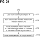
- FIGs. 28 and 29 are flowcharts of the laser-beam machining method according to an embodiment, as an example.
- the laser-beam working machine 1 used in the laser-beam machining method according to an embodiment may be the laser-beam working machine 1A according to the first embodiment, the laser-beam working machine 1B according to the second embodiment, or another laser-beam working machine. Since each component element of the laser-beam working machine 1 has been described in the first embodiment or the second embodiment, the repeated description of each configuration of the laser-beam working machine 1 will be omitted.
- a first step ST1 the workpiece W is machined by irradiating the workpiece W with a laser beam from the laser head 20.
- the first step ST1 is a first machining step.
- the first machining step (first step ST1) is performed, in a state in which the first part W1 of the workpiece W (more specifically, the base end portion Wb of the workpiece W) is held by the grip member 31 of the first chuck 3 and the second part W2 of the workpiece W is interposed by the plurality of guide rollers 41 of the second chuck 4 located on the first direction DR1 side relative to the first chuck 3.
- the workpiece W (more specifically, the long workpiece WL) is supported by the grip members 31 of the first chuck 3 and the plurality of guide rollers 41 of the second chuck 4.
- the workpiece W is machined in a stable manner, with the deflection of the workpiece W eliminated or minimized.
- a third part W3 of the workpiece W may be additionally supported by the first support member 72, which is provided between the first chuck 3 and the second chuck 4.
- a second step ST2 the workpiece W is moved relatively to the laser head 20 and the plurality of guide rollers 41.
- the second step ST2 is a first moving step.
- the first moving step (second step ST2) is performed by moving the first chuck 3, which holds the workpiece W, in the first direction DR1 toward the laser head 20.
- the workpiece W (more specifically, the long workpiece WL) is supported by the grip members 31 of the first chuck 3 and the plurality of guide rollers 41 of the second chuck 4.
- the workpiece W can be moved in the first direction DR1 in a stable manner.
- the first moving step may be performed, in a state in which the third part W3 of the workpiece W is additionally supported by the first support member 72, which is provided between the first chuck 3 and the second chuck 4.
- the first machining step (more specifically, irradiating the workpiece W with the laser beam LA from the laser head 20) and the first moving step (more specifically, moving the first chuck 3 together with the workpiece W in the first direction DR1 ) may be performed simultaneously, sequentially, or alternately.
- moving the first chuck 3, which holds the workpiece W, in the first direction DR1 toward the laser head 20, and moving the first chuck 3, which holds the workpiece W, in the second direction DR2 away from the laser head 20 may be alternately performed.
- a third step ST3 the workpiece W is rotated about the first axis AT, which is parallel to the first direction DR1.
- the third step ST3 is a first rotating step.
- the first rotating step (third step ST3) includes synchronously rotating the grip member 31, which holds the workpiece W, and the plurality of guide rollers 41 about the first axis AT (see an arrow R1).
- the first rotating step is performed, in a state in which the first part W1 of the workpiece W is held by the grip member 31 of the first chuck 3 and the second part W2 of the workpiece W is supported by the plurality of guide rollers 41 of the second chuck 4.
- the workpiece W (more specifically, the long workpiece WL) can be rotated about the first axis AT in a stable manner.
- the first machining step (more specifically, irradiating the workpiece W with the laser beam LA from the laser head 20) and the first rotating step (more specifically, rotating the workpiece W about the first axis AT) may be performed simultaneously, sequentially, or alternately.
- the first moving step (more specifically, moving the first chuck 3 together with the workpiece W in the first direction DR1 ) and the first rotating step (more specifically, rotating the workpiece W about the first axis AT) may be performed simultaneously, sequentially, or alternately.
- the length of the workpiece W, which is held by the grip member 31 of the first chuck 3, is shortened, and the workpiece W become the short workpiece WS.
- the short workpiece WS which is held by the grip member 31, is moved to approach the laser head 20.
- the fourth step ST4 is a retracting step.
- the retracting step (fourth step ST4) is performed by the roller mover 43 moving the plurality of guide rollers 41 respectively in the directions away from the first axis AT.
- the fifth step ST5 is a relatively rotating step.
- the relatively rotating step includes respectively aligning the rotation phases of the plurality of grippers 32 about the first axis AT with a plurality of corner portions C of the rectangular inner region SP1, which is defined by the plurality of guide rollers 41. More specifically, in a case where N is defined as any integer equal to or greater than "0", the relatively rotating step includes rotating the plurality of guide rollers 41 relatively to the grip member 31 about the first axis AT by (45 + N ⁇ 90) degrees.
- the relatively rotating step may be performed by the first rotation drive 36 rotating the grip member 31 about the first axis AT, or may be performed by the second rotation drive 46 rotating the plurality of guide rollers 41 about the first axis AT.
- the relatively rotating step may be omitted.
- the first chuck 3including the grip member 31, which holds the workpiece W is further moved in the first direction DR1 (see an arrow AR1).
- the sixth step ST6 is a second moving step.
- the second moving step includes further moving the first chuck 3 in the first direction DR1 so that the end face 31e of the grip member 31 moves between the plurality of guide rollers 41 and approaches the laser head 20.
- the plurality of guide rollers 41 are retracted beforehand by performing of the above-described retracting processing, and thus the end face 31e of the grip member 31 does not collide with the plurality of guide rollers 41.
- the position of the end face 31e of the grip member 31 of the first chuck 3 is changed to the first position P1 on the first direction DR1 side relative to the plurality of guide rollers 41 from the second position P2 on the second direction DR2 side relative to the plurality of guide rollers 41 (see FIG. 26 ).
- the second moving step includes inserting the grip member 31 of the first chuck 3 on the inner sides of the plurality of guide rollers 41 of the second chuck 4 (hereinafter, referred to as an "inserting step"). It is to be noted that in a case where the inserting step is performed after the above-described relatively rotating step is performed, performing of the inserting step causes the plurality of grippers 32 of the grip member 31 to be respectively arranged in the plurality of corner portions C of the rectangular inner region SP1, which is defined by the plurality of guide rollers 41.
- a seventh step ST7 the workpiece W is further machined by irradiating the workpiece W with a laser beam from the laser head 20.
- the seventh step ST7 is a second machining step.
- the workpiece W (more specifically, the short workpiece WS) is irradiated with the laser beam LA from the laser head 20.
- the end face 31e of the grip member 31 is located on the first direction DR1 side relative to the plurality of guide rollers 41, and thus the length of the remaining workpiece produced by machining the workpiece W can be shortened.
- an eighth step ST8 the workpiece W is moved in either the first direction DR1 or the second direction DR2.
- the eighth step ST8 is a third moving step.
- the third moving step (eighth step ST8) is performed by moving the first chuck 3, which holds the workpiece W, in either the first direction DR1 or the second direction DR2. In this manner, the laser-beam irradiated position of the workpiece W in the direction along the first direction DR1 is changed.
- the second machining step (more specifically, irradiating the workpiece W with the laser beam LA from the laser head 20) and the third moving step (more specifically, moving the workpiece W in either the first direction DR1 or the second direction DR2 ) may be performed simultaneously, sequentially, or alternately.
- a ninth step ST9 the grip member 31, which holds the workpiece W (more specifically, the short workpiece WS), is rotated about the first axis AT.
- the ninth step ST9 is a second rotating step.
- the second rotating step (ninth step ST9) is performed in the state in which the grip member 31 is inserted on the inner sides of the plurality of guide rollers 41.
- the grip member 31 and the plurality of guide rollers 41 are preferably rotated about the first axis AT synchronously.
- the second machining step and the second rotating step are performed simultaneously (in other words, the grip member 31, which is provided on the inner sides of the plurality of guide rollers 41, is rotated about the first axis AT, and the workpiece W, which is held by the grip member 31, is irradiated with a laser beam), and thus the workpiece W is separated into the machined product Wt and the remaining workpiece Wr.
- a tenth step ST10 the remaining workpiece Wr, which has been produced by the laser-beam machining of the workpiece W, is unloaded.
- the tenth step ST10 is a remaining workpiece unloading step.
- the remaining workpiece unloading step (a tenth step ST10) is automatically performed by the grip member 31 releasing the remaining workpiece Wr (in other words, holding of the remaining workpiece Wr by the grip member 31 is released), in a state in which the end face 31e of the grip member 31 of the first chuck 3 is located on the first direction DR1 side relative to the plurality of guide rollers 41. More specifically, holding of the remaining workpiece Wr by the grip member 31 is released, and thus the remaining workpiece Wr is dropped downward from the grip member 31.
- the remaining workpiece Wr is released, in the state in which the end face 31e of the grip member 31 is located on the first direction DR1 side relative to the plurality of guide rollers 41, and thus the remaining workpiece Wr is unloaded with certainty to the first direction DR1 side relative to the plurality of guide rollers 41.
- the remaining workpiece Wr is automatically unloaded by the grip member 31 releasing holding of the remaining workpiece Wr, and thus a pusher for pushing out the remaining workpiece Wr from the grip member 31 to the first direction DR1 side can be omitted. By omitting the pusher and the operation of the pusher, the time needed for unloading the remaining workpiece Wr can be shortened.
- Processor 82 ... Memory, 84 ... Communication circuit, 86 ... Input device, 88 ... Bus, 91 ... First base, 92 ... Second base, 320n ... Inner side surface, 320u ... Outer side surface, 822 ... Machining program, 862 ... Display with touch panel, C ... Corner portion, C1 ... First corner portion, C2 ... Second corner portion, C3 ... Third corner portion, C4 ... Fourth corner portion, MR ... Workpiece machining region, S 1 ... First control signal, S2 ... Second control signal, S3 ... Third control signal, S4 ... Fourth control signal, S5 ... Fifth control signal, S6 ... Sixth control signal, S7 ... Seventh control signal, SP ...
Landscapes
- Engineering & Computer Science (AREA)
- Physics & Mathematics (AREA)
- Optics & Photonics (AREA)
- Mechanical Engineering (AREA)
- Plasma & Fusion (AREA)
- Laser Beam Processing (AREA)
Abstract
Description
- The present invention relates to laser-beam working machine and laser-beam machining method.
- A laser-beam working machine using a laser beam for machining a long workpiece is known.
- As a related technique,
Patent Document 1 discloses a vise docking mechanism (chuck docking mechanism) of a cutting machine. The vise docking mechanism described inPatent Document 1 includes a body vise provided in close proximity to a cutting position of a material, a feed vise for feeding the material by a constant size, and a front vise for holding and pulling out a front end of the material. In the vise docking mechanism described inPatent Document 1, the docking vise can be formed by docking the feed vise with the body vise, the docking vise can be advanced in a direction toward the front vise, and the docking vise can be retracted in a direction away from the front vise. - PTL1:
JP H05-253741 A - It is an object of the present invention to provide a laser-beam working machine and a laser-beam machining method that are capable of shortening the length of a remaining workpiece produced by machining of a workpiece extending in a first direction.
- According to some embodiments of the present invention, a laser-beam working machine includes a laser head, a first chuck, a second chuck, and a mover. The laser head is configured to irradiate a workpiece extending in a first direction with a laser beam to machine the workpiece. The first chuck includes a grip member configured to hold the workpiece, and the first chuck is movable in the first direction. The second chuck is provided between the laser head and the first chuck in a direction along the first direction, the second chuck includes a plurality of guide rollers configured to interpose the workpiece and guide a movement of the workpiece in the first direction. The mover is configured to move the first chuck in the first direction for an end face of the grip member to pass through the plurality of guide rollers and approach the laser head.
- According to some embodiments of the present invention, a laser-beam machining method includes a step of machining a workpiece, by irradiating the workpiece with a laser beam from a laser head, in a state in which a first part of the workpiece is held by a grip member of a first chuck and a second part of the workpiece is interposed between a plurality of guide rollers of a second chuck located in a first direction relative to the first chuck. The method also includes a step of moving the first chuck in the first direction toward the laser head to move the workpiece relatively to the laser head and the plurality of guide rollers. The method also includes a step of further moving the first chuck in the first direction for an end face of the grip member to pass through the plurality of guide rollers and approach the laser head. The method also includes a step of further machining the workpiece, by irradiating the workpiece with the laser beam from the laser head, in a state in which the end face of the grip member is located on the first direction side relative to the plurality of guide rollers.
- The present invention provides a laser-beam working machine and a laser-beam machining method that are capable of shortening the length of a remaining workpiece produced by machining of a workpiece extending in a first direction.
-
- [
FIG. 1] FIG. 1 is a side view of a laser-beam working machine according to a first embodiment, schematically illustrating the laser-beam working machine. - [
FIG. 2] FIG. 2 is a side view of the laser-beam working machine according to the first embodiment, schematically illustrating the laser-beam working machine. - [
FIG. 3] FIG. 3 is a side view of the laser-beam working machine according to the first embodiment, schematically illustrating the laser-beam working machine. - [
FIG. 4] FIG. 4 is a side view of the laser-beam working machine according to the first embodiment, schematically illustrating the laser-beam working machine. - [
FIG. 5] FIG. 5 is a side view of the laser-beam working machine according to the first embodiment, schematically illustrating the laser-beam working machine. - [
FIG. 6] FIG. 6 is a side view of the laser-beam working machine according to the first embodiment, schematically illustrating the laser-beam working machine. - [
FIG. 7] FIG. 7 is a side view of the laser-beam working machine according to the first embodiment, schematically illustrating the laser-beam working machine. - [
FIG. 8] FIG. 8 is a side view of a laser-beam working machine according to a second embodiment, schematically illustrating the laser-beam working machine. - [
FIG. 9] FIG. 9 is a side view of the laser-beam working machine according to the second embodiment, schematically illustrating an enlarged part of the laser-beam working machine. - [
FIG. 10] FIG. 10 is a side view of the laser-beam working machine according to the second embodiment, schematically illustrating the enlarged part of the laser-beam working machine. - [
FIG. 11] FIG. 11 is a cross-sectional view taken along the arrow E-E inFIG. 8 . - [
FIG. 12] FIG. 12 is a front view of a second chuck, schematically illustrating an example of the second chuck. - [
FIG. 13] FIG. 13 is a cross-sectional view taken along the arrow F-F inFIG. 8 . - [
FIG. 14] FIG. 14 is a cross-sectional view of a grip member and a plurality of guide rollers, schematically illustrating a state in which the grip member is inserted on inner sides of the plurality of guide rollers. - [
FIG. 15] FIG. 15 is a cross-sectional view of the grip member and the plurality of guide rollers, schematically illustrating the state in which the grip member is inserted on the inner sides of the plurality of guide rollers. - [
FIG. 16] FIG. 16 is a cross-sectional view of the grip member and the plurality of guide rollers, schematically illustrating the state in which the grip member is inserted on the inner sides of the plurality of guide rollers. - [
FIG. 17] FIG. 17 is a cross-sectional view of the grip member and the plurality of guide rollers, schematically illustrating the state in which the grip member is inserted on the inner sides of the plurality of guide rollers. - [
FIG. 18] FIG. 18 is a side view of the laser-beam working machine according to the second embodiment, schematically illustrating an enlarged part of the laser-beam working machine. - [
FIG. 19] FIG. 19 is a side view of the laser-beam working machine according to the second embodiment, schematically illustrating the enlarged part of the laser-beam working machine. - [
FIG. 20] FIG. 20 is a side view of the laser-beam working machine according to the second embodiment, schematically illustrating the enlarged part of the laser-beam working machine. - [
FIG. 21] FIG. 21 a functional block diagram of a controller and a plurality of devices to be controlled by the controller, schematically illustrating the controller and the devices. - [
FIG. 22] FIG. 22 is a block diagram of a hardware configuration of the controller, as an example. - [
FIG. 23] FIG. 23 schematically illustrates a state in which rotation phases of a plurality of grippers are respectively coincident with rotation phases of the plurality of guide rollers. - [
FIG. 24] FIG. 24 schematically illustrates a state in which the rotation phases of the plurality of grippers and the rotation phases of the plurality of guide rollers are shifted from each other by 45 degrees. - [
FIG. 25] FIG. 25 is a side view of the laser-beam working machine according to the second embodiment, schematically illustrating the enlarged part of the laser-beam working machine. - [
FIG. 26] FIG. 26 schematically illustrates one processing step in a laser-beam machining method according to an embodiment. - [
FIG. 27] FIG. 27 schematically illustrates another processing step in the laser-beam machining method according to an embodiment. - [
FIG. 28] FIG. 28 is a flowchart of the laser-beam machining method according to an embodiment, as an example. - [
FIG. 29] FIG. 29 is a flowchart of the laser-beam machining method according to an embodiment, as an example. - Hereinafter, by referring to the drawings, a laser-
beam working machine 1 and a laser-beam machining method in embodiments will be described. It is to be noted that in the following description of the embodiments, identical reference numerals are used to denote identical portions, members, or components having identical functions, and redundant description of identical portions, members, or components will be omitted. - Herein, the movement direction of a
first chuck 3 when thefirst chuck 3 moves toward alaser head 20 will be defined as a "first direction DR1", and the direction opposite to the first direction DR1 will be defined as a "second direction DR2". The first direction DR1 is coincident with a direction from a base end portion Wb of a workpiece W (in other words, an end portion on the second direction DR2 side of the workpiece W) to be machined by alaser head 20 toward a tip end portion Wa of the workpiece W (in other words, an end portion on the first direction DR1 side of the workpiece W). - By referring to
FIGs. 1 to 7 , a laser-beam working machine 1A according to a first embodiment will be described.FIGs. 1 to 7 are side views of the laser-beam working machine 1A according to the first embodiment, schematically illustrating the laser-beam working machine 1A. - The laser-
beam working machine 1A according to the first embodiment includes alaser head 20, afirst chuck 3, asecond chuck 4, and amover 6. - The
laser head 20 machines the workpiece W by irradiating the workpiece W extending in the first direction DR1 with a laser beam LA. Thelaser head 20 may cut the workpiece W by irradiating the workpiece W with the laser beam LA, or may form a hole in the workpiece W by irradiating the workpiece W with the laser beam LA. In an example ofFIG. 1 , the workpiece W is a long workpiece WL. As illustrated inFIG. 2 , by cutting the long workpiece WL with a laser beam, thelaser head 20 is capable of producing a machined product Wt and a short workpiece WS from the long workpiece WL. In other words, the short workpiece WS is produced by laser-beam machining of the long workpiece WL. As illustrated inFIG. 2 , only agrip member 31 of thefirst chuck 3 is capable of supporting the short workpiece WS. - The long workpiece WL and the short workpiece WS will be hereinafter collectively referred to as "workpiece W". In addition, the workpiece that can be supported only by the
grip member 31 of thefirst chuck 3 will be referred to as the "short workpiece WS". - The
first chuck 3 includes thegrip member 31 for holding the workpiece W. Thefirst chuck 3 is movable together with the workpiece W in the first direction DR1. - As illustrated in
FIG. 1 , thesecond chuck 4 is provided between thelaser head 20 and thefirst chuck 3 in a direction along the first direction DR1. More specifically, thesecond chuck 4 is provided on the first direction DR1 side relative to thefirst chuck 3, and thelaser head 20 is provided on the first direction DR1 side relative to thesecond chuck 4. Thesecond chuck 4 includes a plurality ofguide rollers 41, which interpose the workpiece W. The plurality ofguide rollers 41 guide the movement of the workpiece W (more specifically, the long workpiece WL) in either the first direction DR1 or the second direction DR2. In the example illustrated inFIG. 1 , each of the plurality ofguide rollers 41 is rotatable about a rotation axis AX, which is perpendicular to the first direction DR1. - The plurality of
guide rollers 41 are provided so as to interpose the workpiece W (more specifically, the long workpiece WL). In the example illustrated inFIG. 1 , the plurality ofguide rollers 41 include: afirst guide roller 41a to be in contact with the workpiece W (more specifically, the long workpiece WL); and asecond guide roller 41b to be in contact with the workpiece W (more specifically, the long workpiece WL). Thesecond guide roller 41b is provided on a side opposite to thefirst guide roller 41a with respect to the workpiece W. - The
mover 6 moves thefirst chuck 3 in either the first direction DR1 or the second direction DR2. As illustrated inFIGs. 2 and3 , themover 6 moves thefirst chuck 3 in the first direction DR1 so that anend face 31e of thegrip member 31 moves between the plurality ofguide rollers 41 and approaches thelaser head 20. In other words, themover 6 moves thefirst chuck 3 in the first direction DR1, thereby moving a tip end portion of the grip member 31 (more specifically, theend face 31e on the first direction DR1 side of the grip member 31) of thefirst chuck 3 to a first position P1 (seeFIG. 3 ) on the first direction DR1 side relative to the plurality ofguide rollers 41 from a second position P2 (seeFIG. 2 ) on the second direction DR2 side relative to the plurality ofguide rollers 41. - In the first embodiment, the position of the
end face 31e of thegrip member 31 of thefirst chuck 3 is changeable to the first position P1 (seeFIG. 3 ) on the first direction DR1 side relative to the plurality ofguide rollers 41 from the second position P2 (seeFIG. 2 ) on the second direction DR2 side relative to the plurality ofguide rollers 41. In this case, as illustrated inFIG. 3 , the base end portion Wb of the workpiece W (more specifically, the short workpiece WS) held by thegrip member 31 can be made closer to thelaser head 20. In this manner, the length of a remaining workpiece Wr (seeFIG. 4 ) produced by machining of the workpiece W extending in the first direction DR1 can be shortened. - In addition, the length of the remaining workpiece Wr is shortened, the amount of unused material is reduced, and the load on the environment is reduced. It is to be noted that herein, the "remaining workpiece Wr" means an end material produced by the laser-beam machining of the workpiece W.
- Subsequently, by referring to
FIGs. 1 to 7 , optionally additional configurations to be adoptable in the first embodiment will be described. - In the example illustrated in
FIG. 2 , themover 6 includes: a drive 61 (more specifically, a motor such as a servo motor), which moves thefirst chuck 3 in either the first direction DR1 or the second direction DR2; and a guide member 62 (for example, a guide rail) for guiding the movement of thefirst chuck 3 in either the first direction DR1 or the second direction DR2. Additionally, themover 6 may include a power transmission member 63 (for example, a ball screw) for converting the power of thedrive 61 into the movement of thefirst chuck 3. It is to be noted that in a case where thedrive 61 is a linear motor, the ball screw can be omitted. Themover 6 may also convert the rotational force of thedrive 61 into the movement of thefirst chuck 3 in either the first direction DR1 or the second direction DR2 via a rack and pinion. In the example illustrated inFIG. 2 , the drive 61 (more specifically, a motor) is provided in afirst base 91. However, alternatively, the drive 61 (more specifically, the motor) may be provided in thefirst chuck 3. In other words, thefirst chuck 3 may be self-propelled. - In the example illustrated in
FIG. 6 , the laser-beam working machine 1A (more specifically, the second chuck 4) includes aroller mover 43, which moves the plurality ofguide rollers 41. Theroller mover 43 moves the plurality ofguide rollers 41 in a direction not parallel to the first direction DR1 (in other words, a direction different from the first direction DR1 and the second direction DR2), between advanced positions (A1, A2) in contact with the workpiece W (more specifically, the long workpiece WL) and retracted positions (B1, B2) that allow theend face 31e of thegrip member 31 to pass through the plurality of guide rollers 41 (seeFIG. 7 ). More specifically, theroller mover 43 moves the plurality ofguide rollers 41 between the advanced positions (A1, A2) in contact with the workpiece W (more specifically, the long workpiece WL) and the retracted positions (B1, B2) in which the distance between each of the plurality ofguide rollers 41 and a first axis AT is longer than the distance between each of the plurality ofguide rollers 41 in the advanced positions (A1, A2) and the first axis AT, and which thus allows theend face 31e of thegrip member 31 to pass through the plurality ofguide rollers 41. It is to be noted that the above-described first axis AT is an axis coincident with the rotation axis of the grip member 31 (in other words, the rotation axis of the workpiece W held by the grip member 31) to be rotated by a first rotation drive 36 as will be described later. In addition, the above-described first axis AT is an axis coincident with the rotation axis of the plurality of guide rollers 41 (in other words, the rotation axis of the workpiece W, which is interposed by the plurality of guide rollers 41) to be rotated by a second rotation drive 46 as will be described later. - The
roller mover 43 includes afirst roller mover 43a, which moves thefirst guide roller 41a between a first advanced position A1 and a first retracted position B1. In addition, theroller mover 43 also includes asecond roller mover 43b, which moves asecond guide roller 41b between a second advanced position A2 and a second retracted position B2. The power source (for example, an actuator or a motor) with which thesecond roller mover 43b moves thesecond guide roller 41b may be identical to or different from the power source (for example, an actuator or a motor) with which thefirst roller mover 43a moves thefirst guide roller 41a. - As illustrated in
FIG. 6 , in a case where the plurality ofguide rollers 41 are in the advanced positions (A1, A2), the workpiece W (more specifically, the long workpiece WL) is supported in a stable manner by thegrip member 31 and the plurality ofguide rollers 41. In addition, as illustrated inFIG. 7 , in a case where the plurality ofguide rollers 41 are in the retracted positions (B1, B2), interference between thegrip member 31, which moves in the first direction DR1, and the plurality ofguide rollers 41 is avoided. - In the example illustrated in
FIG. 6 , the plurality ofguide rollers 41 includes thefirst guide roller 41a and thesecond guide roller 41b. The plurality ofguide rollers 41 are arranged in the vicinity of thelaser head 20, and are capable of supporting a tip end part of the long workpiece WL or a central part of the long workpiece WL. - With regard to the magnitude of holding force for holding the workpiece W by the plurality of
guide rollers 41, any magnitude is applicable, as long as it is possible to guide the movement of the workpiece W in either the first direction DR1 or the second direction DR2. Such holding force may be substantially zero. - The
first guide roller 41a is supported to be rotatable about a first rotation axis AX1 by a firstroller support member 42a, which is included in thesecond chuck 4. The first rotation axis AX1 is perpendicular to the first direction DR1. - The
second guide roller 41b is rotatably supported about a second rotation axis AX2 by a secondroller support member 42b, which is included in thesecond chuck 4. The second rotation axis AX2 is perpendicular to the first direction DR1. In addition, in the example illustrated inFIG. 6 , the second rotation axis AX2 is parallel to the first rotation axis AX1. - As illustrated in
FIG. 7 , in a state in which thegrip member 31 is inserted on inner sides of the plurality of guide rollers 41 (more specifically, in a state in which thegrip member 31 is partially provided in an inner region SP, which is defined by the plurality of guide rollers 41), thegrip member 31 is rotatable about the first axis AT (see an arrow R2). In this case, in a state in which thegrip member 31 is located in the vicinity of thelaser head 20, the posture of the workpiece W (more specifically, the short workpiece WS) about the first axis AT is changeable. It is to be noted that the first axis AT is an axis parallel to the first direction DR1. - In the example illustrated in
FIG. 7 , in a state in which thegrip member 31 is inserted on the inner sides of the plurality ofguide rollers 41, the plurality ofguide rollers 41 are rotatable about the first axis AT together with thegrip member 31. In this case, in order to rotate thegrip member 31 about the first axis AT, there is no need to additionally retract the plurality ofguide rollers 41 respectively in directions away from the first axis AT. - In the example illustrated in
FIG. 6 , thefirst chuck 3 includes afirst rotation drive 36, which rotates thegrip member 31 about the first axis AT, which is parallel to the first direction DR1. Thefirst rotation drive 36 rotates thegrip member 31 and afirst rotor 35, which supports thegrip member 31, about the first axis AT. In the example illustrated inFIG. 7 , thefirst rotation drive 36 is capable of rotating thegrip member 31 about the first axis AT, in the state in which thegrip member 31 is inserted on the inner sides of the plurality ofguide rollers 41. - In the example illustrated in
FIG. 6 , thesecond chuck 4 includes asecond rotation drive 46, which rotates the plurality ofguide rollers 41 about the first axis AT, which is parallel to the first direction DR1. Thesecond rotation drive 46 rotates the plurality ofguide rollers 41 and asecond rotor 45, which supports the plurality ofguide rollers 41, about the first axis AT. In the example illustrated inFIG. 7 , thesecond rotation drive 46 is capable of rotating the plurality ofguide rollers 41 about the first axis AT, in the state in which thegrip member 31 is inserted on the inner sides of the plurality ofguide rollers 41. - In a case where the laser-
beam working machine 1A includes two rotation drives (36, 46), the long workpiece WL, which is supported by both thefirst chuck 3 and thesecond chuck 4, is made rotatable about the first axis AT in a stable manner. - In addition, in the case where the laser-
beam working machine 1A includes the two rotation drives (36, 46), the plurality ofguide rollers 41 and thegrip member 31 are made rotatable about the first axis AT in a smooth manner, in the state in which thegrip member 31 is inserted on the inner sides of the plurality of guide rollers 41 (seeFIG. 7 ). - Alternatively, only one of the
first rotor 35 and thesecond rotor 45 may be driven to actively rotate about the first axis AT by the rotation drive, and the other one of thefirst rotor 35 and thesecond rotor 45 may passively rotate about the first axis AT. In this case, the other one of thefirst rotor 35 and thesecond rotor 45 is supported by a support member so as to be freely rotatable about the first axis AT via a bearing. - The
grip member 31 is capable of holding the workpiece W (more specifically, the base end portion Wb of the workpiece W). In the example illustrated inFIG. 3 , thegrip member 31 includes: afirst gripper 32a to be in contact with the workpiece W; and asecond gripper 32b to be in contact with the workpiece W. Thesecond gripper 32b is provided on a side opposite to thefirst gripper 32a with respect to the workpiece W. In addition, in the example illustrated inFIG. 3 , thegrip member 31 includes: a firstgripper support body 33a, which supports thefirst gripper 32a; and a secondgripper support body 33b, which supports thesecond gripper 32b. - In the example illustrated in
FIG. 5 , in the state in which thegrip member 31 is inserted on the inner sides of the plurality ofguide rollers 41, thegrip member 31 is capable of releasing holding the workpiece W (for example, holding the remaining workpiece Wr produced by the laser-beam machining of the workpiece W). More specifically, as illustrated inFIGs. 4 and5 , in the state in which thegrip member 31 is inserted on the inner sides of the plurality ofguide rollers 41, thefirst gripper 32a and thesecond gripper 32b are respectively capable of retracting in the directions away from the first axis AT (more specifically, in directions respectively from the first axis AT toward the plurality of guide rollers 41). - In the example illustrated in
FIG. 5 , in a state in which theend face 31e of thegrip member 31 is located at the first position P1 on the first direction DR1 side relative to the plurality ofguide rollers 41, holding of the workpiece W (more specifically, holding of the remaining workpiece Wr) by thegrip member 31 is releasable. In this case, the remaining workpiece Wr can be dropped onto the first direction DR1 side (in other words, the workpiece machining area side where the machining is performed by the laser head 20) relative to the plurality ofguide rollers 41. In the example illustrated inFIG. 5 , it is unlikely that the remaining workpiece Wr will drop onto the second direction DR2 side relative to the plurality ofguide rollers 41. - In the example illustrated in
FIGs. 4 and5 , the laser-beam working machine 1A (more specifically, the first chuck 3) includes agripper mover 34, which moves the plurality ofgrippers 32 including thefirst gripper 32a and thesecond gripper 32b between holding positions (A3, A4) in contact with the workpiece (more specifically, the remaining workpiece Wr of the workpiece) and release positions (B3, B4) spaced apart from the workpiece (more specifically, the remaining workpiece Wr of the workpiece). Thegripper mover 34 includes: afirst gripper mover 34a, which moves thefirst gripper 32a between a first holding position A3 and a first release position B3; and thesecond gripper mover 34b, which moves thesecond gripper 32b between a second holding position A4 and a second release position B4. The power source (for example, an actuator or a motor) with which thesecond gripper mover 34b moves thesecond gripper 32b may be identical to or different from the power source (for example, an actuator or a motor) with which thefirst gripper mover 34a moves thefirst gripper 32a. - In the example illustrated in
FIGs. 4 and5 , thegripper mover 34 moves the plurality ofgrippers 32, which include thefirst gripper 32a and thesecond gripper 32b, from the holding positions (A3, A4) in contact with the remaining workpiece Wr of the workpiece to the release positions (B3, B4) respectively toward the plurality ofguide rollers 41. As a result, the remaining workpiece Wr is released from thegrip member 31, and the remaining workpiece Wr drops onto the first direction DR1 side relative to the plurality of guide rollers 41 (see an arrow D1 inFIG. 5 ). Therefore, a pusher for pushing out the remaining workpiece Wr from thegrip member 31 to the first direction DR1 side can be omitted. The pusher and the operation of the pusher are omitted, and thus the time needed for unloading the remaining workpiece Wr can be shortened. - In the first embodiment, the workpiece (see
FIG. 1 ) is, for example, a pipe Wp, which extends in the first direction DR1. In addition, the short workpiece WS (seeFIG. 2 ) is a short pipe that is produced by the laser-beam machining of the pipe Wp and that can be supported only by thegrip member 31. The cross-sectional shape of the pipe Wp in a direction perpendicular to the first direction DR1 may be rectangular, circular, or triangular. The workpiece W may also be a workpiece other than the pipe. For example, the workpiece W may be a long workpiece having a letter C-shaped cross-section, a long workpiece having a letter H-shaped cross-section, or a long workpiece having a letter L-shaped cross-section. - By referring to
FIGs. 8 to 25 , a laser-beam working machine 1B according to a second embodiment will be described.FIG. 8 is a side view of the laser-beam working machine 1B according to the second embodiment, schematically illustrating the laser-beam working machine 1B.FIGs. 9 and10 are side views of the laser-beam working machine 1B according to the second embodiment, each illustrating an enlarged part of the laser-beam working machine 1B.FIG. 11 is a cross-sectional view taken along the arrow E-E inFIG. 8 .FIG. 12 is a front view of thesecond chuck 4, schematically illustrating the second chuck as an example.FIG. 13 is a cross-sectional view taken along the arrow F-F inFIG. 8 .FIGs. 14 to 17 are cross-sectional views of agrip member 31 and a plurality ofguide rollers 41, each schematically illustrating the state in which thegrip member 31 is inserted on the inner sides of the plurality ofguide rollers 41. It is to be noted thatFIG. 14 is a cross-sectional view on a plane parallel to the first axis AT, andFIGs. 15 to 17 are each a cross-sectional view on a plane perpendicular to a first axis AT and passing through athird guide roller 41c and afourth guide roller 41d.FIGs. 18 to 20 are each a side view of the laser-beam working machine 1B according to the second embodiment, schematically illustrating an enlarged part of the laser-beam working machine 1B.FIG. 21 is a functional block diagram of acontroller 8 and a plurality of devices to be controlled by thecontroller 8, schematically illustrating the controller and the plurality of devices.FIG. 22 is a block diagram of thecontroller 8, schematically illustrating a hardware configuration of the controller.FIG. 23 schematically illustrates a state in which the rotation phases of a plurality ofgrippers 32 are coincident with the rotation phases of the plurality ofguide rollers 41.FIG. 24 schematically illustrates a state in which the rotation phases of the plurality ofgrippers 32 and the rotation phases of the plurality ofguide rollers 41 are shifted from each other by 45 degrees.FIG. 25 is a side view of the laser-beam working machine 1B according to the second embodiment, schematically illustrating the enlarged part of the laser-beam working machine 1B. It is to be noted that inFIGs. 8 to 10 ,18 to 20 , and25 , in order to make an inner state of thesecond chuck 4 recognizable, thesecond chuck 4 is partially cut out, and a cross-sectional view of such a cut out part is illustrated. - In the second embodiment, the following description will mainly focus on those respects in which the second embodiment is different from the first embodiment, and those respects already described in the first embodiment will not be described in the second embodiment to avoid redundancy. Thus, it will be readily appreciated that those respects that are not explicitly described in the second embodiment but are described in the first embodiment apply in the second embodiment. Conversely, all respects to be described in the second embodiment are applicable to the first embodiment.
- As illustrated in
FIG. 8 , the laser-beam working machine 1B according to the second embodiment includes: alaser head 20; afirst chuck 3; asecond chuck 4; and amover 6. - As illustrated in
FIG. 9 , by irradiating a workpiece W, which extends in a first direction DR1, with a laser beam LA, thelaser head 20 machines the workpiece W. Thefirst chuck 3 includes agrip member 31 for holding the workpiece W, and is movable together with the workpiece W in the first direction DR1. Thesecond chuck 4 is provided between thelaser head 20 and thefirst chuck 3 in a direction along the first direction DR1. In addition, thesecond chuck 4 includes a plurality ofguide rollers 41. The plurality ofguide rollers 41 interpose the workpiece W, and guide the movement of the workpiece W in the first direction DR1. As illustrated inFIG. 10 , themover 6 is capable of moving thefirst chuck 3 in the first direction DR1 so that anend face 31e of thegrip member 31 moves among the plurality ofguide rollers 41 and approaches thelaser head 20. In other words, themover 6 is capable of moving the position of theend face 31e on the first direction DR1 side of thegrip member 31 to a first position P1 on the first direction DR1 side relative to the plurality ofguide rollers 41 from a second position P2 on the second direction DR2 side relative to the plurality ofguide rollers 41. - Therefore, the second embodiment has effects similar to those in the first embodiment.
- Subsequently, by referring now to
FIGs. 8 to 25 , optionally additional configurations to be adoptable in the second embodiment will be described. -
FIG. 11 is a cross-sectional view taken along the arrow E-E inFIG. 8 . In the example illustrated inFIG. 11 , thesecond chuck 4 includes a plurality ofguide rollers 41, which includes afirst guide roller 41a and asecond guide roller 41b. Thesecond chuck 4 may include thefirst guide roller 41a, thesecond guide roller 41b, athird guide roller 41c, and afourth guide roller 41d. - In the example illustrated in
FIG. 11 , the positions of thethird guide roller 41c and thefourth guide roller 41d in directions along the first direction DR1 are slightly different from the positions of thefirst guide roller 41a and thesecond guide roller 41b in the directions along the first direction DR1. Hence, when viewed in a direction along the second direction DR2, thethird guide roller 41c is movable to a position partially overlapping thefirst guide roller 41a and thesecond guide roller 41b. In addition, when viewed in the direction along the second direction DR2, thefourth guide roller 41d is movable to a position partially overlapping thefirst guide roller 41a and thesecond guide roller 41b. - The
second chuck 4 includes a plurality ofroller support members 42, which respectively support the plurality ofguide rollers 41. Each of the plurality ofroller support members 42 is, for example, a plate-shaped body. In the example illustrate inFIG. 12 , thesecond chuck 4 includes: a firstroller support member 42a, which supports thefirst guide roller 41a to be rotatable about the first rotation axis AX1; a secondroller support member 42b, which supports thesecond guide roller 41b to be rotatable about the second rotation axis AX2, and a thirdroller support member 42c, which supports thethird guide roller 41c to be rotatable about a third rotation axis AX3; and a fourthroller support member 42d, which supports thefourth guide roller 41d to be rotatable about a fourth rotation axis AX4. - In the example illustrated in
FIG. 12 , the first rotation axis AX1 is perpendicular to the first direction DR1, and the second rotation axis AX2 is parallel to the first rotation axis AX1. In addition, the third rotation axis AX3 is perpendicular to both the first direction DR1 and the first rotation axis AX1, and the fourth rotation axis AX4 is parallel to the third rotation axis AX3. - In the example illustrated in
FIG. 12 , when viewed in the direction along the second direction DR2, a rectangular inner region SP1 is defined by the plurality ofguide rollers 41. More specifically, when viewed in the direction along the second direction DR2, the rectangular inner region SP1 is defined by thefirst guide roller 41a, thesecond guide roller 41b, thethird guide roller 41c, and thefourth guide roller 41d. In a case where the plurality ofguide rollers 41 are capable of defining the rectangular inner region SP1, the plurality ofguide rollers 41 are capable of guiding the workpiece W having a rectangular cross-section (for example, a square cross-section, a rectangular cross-section) in a stable manner. It is needless to say that the plurality ofguide rollers 41 are also capable of guiding the workpiece W having any cross-sectional shape other than the rectangular one (for example, a circular cross-sectional shape, a letter C-shaped cross-sectional shape, a letter H-shaped cross-sectional shape, and the like). - In the example illustrated in
FIG. 11 , the laser-beam working machine 1B (more specifically, the second chuck 4) includes aroller mover 43, which moves the plurality ofguide rollers 41. Theroller mover 43 moves the plurality ofguide rollers 41 in a direction not parallel to the first direction DR1 (for example, a direction perpendicular to the first direction DR1) between the advanced positions in contact with the workpiece W and the retracted positions (seeFIG. 12 ) that allow theend face 31e of thegrip member 31 to move among the plurality ofguide rollers 41. - As illustrated in
FIG. 11 , a direction from thefirst guide roller 41a toward thesecond guide roller 41b is defined as a third direction DR3, and a direction from thesecond guide roller 41b toward thefirst guide roller 41a is defined as a fourth direction DR4. Thethird direction DR 3 and the fourth direction DR4 are each perpendicular to the first direction DR1, for example. - In the example illustrated in
FIG. 11 , theroller mover 43 includes afirst roller mover 43a (for example, an actuator or a motor), which moves thefirst guide roller 41a in the third direction DR3 (or the fourth direction DR4). In a case where the movable range of thefirst guide roller 41a in a direction parallel to the third direction DR3 is defined as a first range, thefirst roller mover 43a is preferably capable of fixing the position of thefirst guide roller 41a at any position within the first range. - In the example illustrated in
FIG. 11 , theroller mover 43 includes asecond roller mover 43b (for example, an actuator or a motor), which moves thesecond guide roller 41b in the fourth direction DR4 (or the third direction DR3). In a case where the movable range of thesecond guide roller 41b in a direction parallel to the third direction DR3 is defined as a second range, thesecond roller mover 43b is preferably capable of fixing the position of thesecond guide roller 41b at any position within the second range. - The power source (for example, an actuator or a motor) with which the
second roller mover 43b moves thesecond guide roller 41b may be identical to or different from the power source (for example, an actuator or a motor) with which thefirst roller mover 43a moves thefirst guide roller 41a. - As illustrated in
FIG. 11 , a direction from thethird guide roller 41c toward thefourth guide roller 41d is defined as a fifth direction DR5, and a direction from thefourth guide roller 41d toward thethird guide roller 41c is defined as a sixth direction DR6. The fifth direction DR5 and the sixth direction DR6 are each perpendicular to the first direction DR1, for example. - In the example illustrated in
FIG. 11 , theroller mover 43 includes athird roller mover 43c, which moves thethird guide roller 41c in the fifth direction DR5 (or the sixth direction DR6). In a case where the movable range of thethird guide roller 41c in a direction parallel to the fifth direction DR5 is defined as a third range, thethird roller mover 43c is preferably capable of fixing the position of thethird guide roller 41c at any position within the third range. - In the example illustrated in
FIG. 11 , theroller mover 43 includes afourth roller mover 43d, which moves thefourth guide roller 41d to the sixth direction DR6 (or the fifth direction DR5). In a case where the movable range of thefourth guide roller 41d in the direction parallel to the fifth direction DR5 is defined as a fourth range, theroller mover 43 is preferably capable of fixing the position of thefourth guide roller 41d at any position within the fourth range. - The power source (for example, an actuator or a motor) with which the
fourth roller mover 43d moves thefourth guide roller 41d may be identical to or different from the power source (for example, an actuator or a motor) with which thethird roller mover 43c moves thethird guide roller 41c. - In the example illustrated in
FIG. 12 , thesecond chuck 4 includes asecond rotor 45 and a second rotation drive 46 (for example, a second motor of a second servo motor or the like). - The
second rotor 45 supports the plurality ofguide rollers 41, a plurality ofroller support members 42, which respectively support the plurality ofguide rollers 41, and theroller mover 43, which moves the plurality ofguide rollers 41. Thesecond rotor 45 has an annular body. In the example illustrated inFIG. 10 , thesecond rotor 45 includes a throughhole 45h into which thegrip member 31 of thefirst chuck 3 is inserted. The throughhole 45h is a hole that allows theend face 31e of thegrip member 31 of thefirst chuck 3 to pass through. - The
second rotation drive 46 rotates thesecond rotor 45 about the first axis AT. Thesecond rotation drive 46 rotates thesecond rotor 45, thereby rotating the plurality ofguide rollers 41, the plurality ofroller support members 42, theroller mover 43, and thesecond rotor 45 integrally about the first axis AT. As illustrated inFIG. 12 , thesecond chuck 4 may include apower transmission member 47, such as a gear, for transmitting driving force of the second rotation drive 46 to thesecond rotor 45. In this case, the drive axis of thesecond rotation drive 46 does not have to be coaxial with the first axis AT. -
FIG. 13 is a cross-sectional view taken along the arrow F-F inFIG. 8 . In the example illustrated inFIG. 13 , thegrip member 31 includes: afirst grip member 31a to be in contact with the workpiece W; and asecond grip member 31b to be in contact with the workpiece W. Thesecond grip member 31b is provided on a side opposite to thefirst grip member 31a with respect to the workpiece W. - The
first grip member 31a includes: afirst gripper 32a, and a firstgripper support body 33a, which supports thefirst gripper 32a. In addition, thesecond grip member 31b includes: asecond gripper 32b; and a secondgripper support body 33b, which supports thesecond gripper 32b. - As illustrated in
FIG. 13 , thegrip member 31 may include: athird grip member 31c to be in contact with the workpiece W; and afourth grip member 31d, which is provided on a side opposite to thethird grip member 31c with respect to the workpiece, and which is to be in contact with the workpiece W. Thethird grip member 31c includes: athird gripper 32c; and a thirdgripper support body 33c, which supports thethird gripper 32c. In addition, thefourth grip member 31d includes: afourth gripper 32d; and a fourthgripper support body 33d, which supports thefourth gripper 32d. In the example illustrated inFIG. 13 , the angle made by a direction from thethird grip member 31c toward thefourth grip member 31d and a direction from thefirst grip member 31a toward thesecond grip member 31b is 90 degrees. - In the example illustrated in
FIG. 14 , thegrip member 31 is rotatable about the first axis AT (see an arrow R2), in a state in which thegrip member 31 is inserted on inner sides of the plurality ofguide rollers 41, in other words, in a state in which thegrip member 31 is partially arranged in an inner region SP, which is defined by the plurality of guide rollers 41 (see the inner region SP surrounded by a dashed line). In this case, in a state in which thegrip member 31 is located in the vicinity of thelaser head 20, the posture of the workpiece W (more specifically, the short workpiece WS) about the first axis AT is changeable. -
FIG. 15 is a cross-sectional view taken along the arrow G-G inFIG. 14 . In the example illustrated inFIGs. 15 and16 , in the state in which thegrip member 31 is inserted on the inner sides of the plurality ofguide rollers 41, the plurality ofguide rollers 41 are rotatable about the first axis AT together with the grip member 31 (see an arrow R2). In this case, in order to rotate thegrip member 31 about the first axis AT, there is no need to additionally retract the plurality ofguide rollers 41 respectively in directions away from the first axis AT. - In the example of
FIG. 16 , thegrip member 31 includes a plurality ofgrippers 32. In addition, in the example illustrated inFIG. 16 , the plurality ofgrippers 32 are respectively arrangeable in a plurality of corner portions C of the rectangular inner region SP1, which is defined by the plurality ofguide rollers 41. In this case, the plurality ofguide rollers 41 are respectively retracted by small distances in the directions away from the first axis AT, and then the plurality ofgrippers 32 are respectively insertable on the inner sides of the plurality ofguide rollers 41. - In the example illustrated in
FIG. 16 , thefirst gripper 32a is provided in a first corner portion C1 of the above-described rectangular inner region SP1, thesecond gripper 32b is provided in a second corner portion C2 of the above-described rectangular inner region SP1, thethird gripper 32c is provided in a third corner portion C3 of the above-described rectangular inner region SP1, and thefourth gripper 32d is provided in a fourth corner portion C4 of the above-described rectangular inner region SP1. - When viewed in a direction along the first direction DR1 (or the second direction DR2), an
outer side surface 320u of each of the plurality ofgrippers 32 preferably has a shape complementary to the corner portion C having a right angle. In this case, each of the plurality ofgrippers 32 can be suitably provided in the corner portion C having a right angle in the rectangular inner region SP1. In addition, aninner side surface 320n of each of the plurality ofgrippers 32 is preferably a planar surface. In this case, the workpiece W is held by the plurality ofgrippers 32 in a stable manner. As illustrated inFIG. 16 , when viewed in a direction along the second direction DR2, each of the plurality ofgrippers 32 may have a substantially right-angled triangular shape. - In the example illustrated in
FIG. 17 , in a state in which thegrip member 31 is inserted on the inner sides of the plurality ofguide rollers 41, thegrip member 31 is capable of releasing holding the workpiece W (for example, holding the remaining workpiece Wr, which is produced by the laser-beam machining of the workpiece W). More specifically, in a state in which thegrip members 31 is provided on the inner sides of the plurality ofguide rollers 41, the plurality ofgrippers 32 are respectively retractable in the directions away from the first axis AT (more specifically, in directions toward the plurality ofguide rollers 41 from the first axis AT). - In the example illustrated in
FIG. 18 , since theend face 31e of thegrip member 31 is located on the first direction DR1 side relative to the plurality ofguide rollers 41, it is unlikely that the remaining workpiece Wr drops onto the second direction DR2 side relative to the plurality ofguide rollers 41. In addition, the remaining workpiece Wr drops onto the first direction DR1 side relative to the plurality ofguide rollers 41 in accordance with the gravity acting on the remaining workpiece Wr. Therefore, a pusher for pushing out the remaining workpiece Wr from thegrip member 31 to the first direction DR1 side can be omitted. By omitting the pusher and the operations of the pusher, the time needed for unloading the remaining workpiece Wr can be shortened. It is to be noted that in the example illustrated inFIG. 18 , the remaining workpiece Wr, which is released from thegrip member 31, is collected by a remainingworkpiece collector 77. - In the example illustrated in
FIG. 13 , the laser-beam working machine 1B (more specifically, the first chuck 3) includes agripper mover 34, which moves the plurality ofgrippers 32. Thegripper mover 34 moves the plurality ofgrippers 32 in a direction not parallel to the first direction DR1 (for example, a direction perpendicular to the first direction DR1) between holding positions in contact with the workpiece W and release positions (if necessary, seeFIG. 17 ) spaced apart from the workpiece W (more specifically, the remaining workpiece Wr). - In the example illustrated in
FIG. 13 , thegripper mover 34 includes afirst gripper mover 34a (for example, an actuator or a motor), which moves thefirst gripper 32a in a direction approaching thesecond gripper 32b (or a direction away from thesecond gripper 32b). Thegripper mover 34 also includes asecond gripper mover 34b (for example, an actuator or a motor), which moves thesecond gripper 32b in a direction approaching thefirst gripper 32a (or a direction away from thefirst gripper 32a). The power source (for example, an actuator or a motor) with which thesecond gripper mover 34b moves thesecond gripper 32b may be identical to or different from the power source (for example, an actuator or a motor) with which thefirst gripper mover 34a moves thefirst gripper 32a. - In the example illustrated in
FIG. 13 , thegripper mover 34 includes athird gripper mover 34c (for example, an actuator or a motor), which moves thethird gripper 32c in a direction approaching thefourth gripper 32d (or a direction away from thefourth gripper 32d). Thegripper mover 34 also includes afourth gripper mover 34d (for example, an actuator or a motor), which moves thefourth gripper 32d in a direction approaching thethird gripper 32c (or a direction away from thethird gripper 32c). The power source (for example, an actuator or a motor) with which thefourth gripper mover 34d moves thefourth gripper 32d may be identical to or different from the power source (for example, an actuator or a motor) with which thethird gripper mover 34c moves thethird gripper 32c. - In the example illustrated in
FIG. 19 , thefirst chuck 3 includes: afirst rotor 35; and a first rotation drive 36 (for example, a first motor such as a first servo motor). Thefirst rotor 35 supports the plurality ofgrippers 32, the plurality ofgripper support bodies 33, and thegripper mover 34. In addition, thefirst rotation drive 36 rotates thefirst rotor 35 about the first axis AT. Thefirst rotation drive 36 rotates thefirst rotor 35, thereby rotating the plurality ofgrippers 32, the plurality ofgripper support bodies 33, and thegripper mover 34 integrally about the first axis AT. In the example illustrated inFIG. 19 , the drive axis of thefirst rotation drive 36 is coaxial with the first axis AT. - In the example of
FIG. 19 , the laser-beam working machine 1B includes two rotation drives (36, 46). In this case, the long workpiece WL, which is supported by both thefirst chuck 3 and thesecond chuck 4, is made rotatable about the first axis AT in a stable manner. - Further, in a case where the laser-
beam working machine 1B includes two rotation drives (36, 46), the plurality ofguide rollers 41 and thegrip member 31 are made rotatable about the first axis AT in a smooth manner, in the state in which thegrip member 31 is inserted on the inner sides of the plurality of guide rollers 41 (seeFIG. 20 ). In the example illustrated inFIG. 20 , thefirst rotation drive 36 is capable of rotating thegrip member 31 about the first axis AT, in the state in which thegrip member 31 is inserted on the inner sides of the plurality ofguide rollers 41, and thesecond rotation drive 46 is capable of rotating the plurality ofguide rollers 41 about the first axis AT, in the state in which thegrip member 31 is inserted on the inner sides of the plurality ofguide rollers 41. - Alternatively, only one of the
first rotor 35 and thesecond rotor 45 may be driven to actively rotate about the first axis AT by the rotation drive, and the other one of thefirst rotor 35 and thesecond rotor 45 may passively rotate about the first axis AT. - In the example illustrated in
FIG. 10 , themover 6 is capable of moving thefirst chuck 3 in the first direction DR1, and is capable of moving thefirst chuck 3 in the second direction DR2. Themover 6 includes: a drive 61 (more specifically, a motor such as a servo motor), which moves thefirst chuck 3; and a guide member 62 (for example, a guide rail), which guides the movement of thefirst chuck 3. Themover 6 may include a power transmission member that converts the power of thedrive 61 into the movement of thefirst chuck 3. Themover 6 may also convert the rotational force of thedrive 61 into the movement of thefirst chuck 3 in either the first direction DR1 or the second direction DR2 via a rack and pinion. - In the example of
FIG. 8 , the laser-beam working machine 1B includesloaders 71. Theloader 71 loads the workpiece W into the laser-beam working machine 1B. More specifically, theloader 71 loads the workpiece W into between thefirst chuck 3 and thesecond chuck 4. The workpiece W that has been loaded is held by thegrip member 31 of thefirst chuck 3. - In the example of
FIG. 8 , the laser-beam working machine 1B includes at least onefirst support member 72, which supports the workpiece W separately from thefirst chuck 3 and thesecond chuck 4. Thefirst support member 72 is provided on the second direction DR2 side relative to thesecond chuck 4. - In the example of
FIG. 8 , thefirst support members 72 are provided between thefirst chuck 3 and thesecond chuck 4. Thefirst support member 72 is configured to support the lower surface of the workpiece W, when the workpiece W moves in the first direction DR1 (or when the workpiece W is machined by the laser beam irradiated from the laser head 20). In this case, deflection of the workpiece W (more specifically, the long workpiece WL) is eliminated or minimized, while the workpiece W is moving or while the workpiece W is being machined. Thefirst support member 72 may be provided on theloader 71, or may be provided on thefirst base 91 of the laser-beam working machine 1B. - The laser-
beam working machine 1B may include asupport member mover 73, which moves thefirst support member 72 between an advanced position at which thesupport member mover 73 is capable of supporting the workpiece W and a retracted position outside the moving path of thefirst chuck 3. In this case, thesupport member mover 73 moves thefirst support member 72 to the retracted position, and thus interference between thefirst chuck 3, which moves in the first direction DR1, and thefirst support member 72 is prevented. - In the example of
FIG. 8 , the laser-beam working machine 1B includesunloaders 75. Theunloader 75 unloads the machined product produced by the laser-beam machining from a workpiece machining region MR of the laser-beam working machine 1B to the outside of the workpiece machining region MR. More specifically, theunloader 75 receives the workpiece W that has been machined by the laser beam irradiated from thelaser head 20, and then unloads the workpiece W from the workpiece machining region MR to the outside of the workpiece machining region. - In the example of
FIG. 8 , the laser-beam working machine 1B includes at least one second support member 76, which supports the workpiece W separately from thefirst chuck 3 and thesecond chuck 4. The second support member 76 is provided on the first direction DR1 side relative to thesecond chuck 4. - The second support member 76 is configured to support the lower surface of the workpiece W, when the workpiece W moves in the first direction DR1 (or when the workpiece W is machined with a laser beam irradiated from the laser head 20). In this case, the deflection of the workpiece W (more specifically, the long workpiece WL) is eliminated or minimized, while the workpiece W is moving or while the workpiece W is being machined. The second support member 76 may be provided on the
unloader 75. - In the example of
FIG. 8 , the laser-beam working machine 1B includes a remainingworkpiece collector 77. The remainingworkpiece collector 77 collects the remaining workpiece Wr, which has been produced by machining of the workpiece W. In the example ofFIG. 8 , the remainingworkpiece collector 77 is provided directly below the workpiece machining region MR. The remainingworkpiece collector 77 may include: acarriage 78; and a remaining workpiece container 79, which is attached to thecarriage 78. - In the example illustrated in
FIG. 10 , thefirst chuck 3 includes: thegrip member 31; thefirst rotor 35, which supports thegrip member 31; arotor support member 37, which supports thefirst rotor 35 to be rotatable about the first axis AT; thefirst rotation drive 36, which rotates thefirst rotor 35 about the first axis AT; and afirst chuck base 38, which supports therotor support member 37. Thefirst rotation drive 36 is attached to therotor support member 37. Thefirst chuck base 38 is slidably movable in either the first direction DR1 or the second direction DR2 along theguide member 62, which is provided on thefirst base 91 of the laser-beam working machine 1B. - In the example illustrated in
FIG. 10 , thesecond chuck 4 includes: the plurality ofguide rollers 41; thesecond rotor 45, which supports the plurality ofguide rollers 41 via theroller support members 42; a secondrotor support member 48, which supports thesecond rotor 45 to be rotatable about the first axis AT; and thesecond rotation drive 46, which rotates thesecond rotor 45 about the first axis AT. Thesecond rotation drive 46 is attached to the secondrotor support member 48. - In the example of
FIG. 10 , the secondrotor support member 48 has an annular body. In the example illustrated inFIG. 10 , the secondrotor support member 48 includes a throughhole 48h, into which thegrip member 31 of thefirst chuck 3 is inserted. In the example illustrated inFIG. 10 , the secondrotor support member 48 prohibits thefirst chuck base 38 of thefirst chuck 3 from moving in the first direction DR1 beyond the secondrotor support member 48. In other words, thefirst chuck base 38 of thefirst chuck 3 is not capable of passing through the throughhole 48h of the secondrotor support member 48. - In the example of
FIG. 10 , thesecond chuck 4 is fixed onto thesecond base 92 of the laser-beam working machine 1B. Alternatively, thesecond chuck 4 may be movable relatively to thesecond base 92 or thefirst base 91 in either the first direction DR1 or the second direction DR2. - In the example illustrated in
FIG. 10 , the laser-beam working machine 1B includes a laser-beam irradiation apparatus 2, and the laser-beam irradiation apparatus 2 includes: thelaser head 20, thelaser head mover 22, which moves thelaser head 20; and athird base 24, which supports thelaser head 20 via thelaser head mover 22. - The
laser head mover 22 moves thelaser head 20. In the example illustrated inFIG. 10 , thelaser head mover 22 includes: avertical drive 22a, which moves thelaser head 20 along a vertical direction; and ahorizontal drive 22b, which moves thelaser head 20 along a horizontal direction. Thelaser head mover 22 may include a tilt device for tilting thelaser head 20 about a horizontal axis. - In the example of
FIG. 10 , thelaser head mover 22 is a device for moving thelaser head 20 two-dimensionally on YZ plane. Alternatively, thelaser head mover 22 may be a device for moving thelaser head 20 three-dimensionally. In other words, thelaser head mover 22 may be capable of moving thelaser head 20 in X direction, capable of moving thelaser head 20 in Y direction, and capable of moving thelaser head 20 in Z direction. It is to be noted that Z direction is a direction parallel to the vertical direction, X direction is a direction parallel to the first direction DR1, and Y direction is a direction perpendicular to both X direction and Z direction. - In the example of
FIG. 10 , thethird base 24 is fixed onto thesecond base 92. Alternatively, thethird base 24 may be directly fixed onto thefirst base 91 of the laser-beam working machine 1B. - In the example of
FIG. 21 , the laser-beam working machine 1B includes thecontroller 8. Thecontroller 8 may include one computer, or may include a plurality of computers. -
FIG. 22 is a block diagram illustrating a hardware configuration of thecontroller 8, as an example. As illustrated inFIG. 22 , thecontroller 8 includes: aprocessor 80; amemory 82; acommunication circuit 84; and an input device 86 (for example, adisplay 862 with a touch panel (seeFIG. 21 )). Theprocessor 80, thememory 82, thecommunication circuit 84, and theinput device 86 are connected with one another via abus 88. Data necessary for the laser-beam machining (for example, shape data of the workpiece W, machining position data of the workpiece W, and the like) may be input into thecontroller 8 via theinput device 86, or may be input from another computer into thecontroller 8 via thecommunication circuit 84. It is to be noted that theinput device 86 is not limited to thedisplay 862 with the touch panel. For example, thecontroller 8 may include: theinput device 86 such as a button, a switch, a lever, a pointing device, or a keyboard; and a display for displaying data that has been input into theinput device 86 or other information. - The
processor 80 executes amachining program 822, which is stored in thememory 82, based on the data that has been input into thecontroller 8, and generates a control signal. In addition, thecommunication circuit 84 transmits such a control signal to devices to be controlled (more specifically, themover 6, thefirst chuck 3, thesecond chuck 4, thelaser head 20, thelaser head mover 22, and the like). In this manner, theprocessor 80 executes themachining program 822, and then thecontroller 8 is capable of controlling themover 6, thefirst chuck 3, thesecond chuck 4, thelaser head 20, and thelaser head mover 22. - The
machining program 822 may include a first program for performing a first moving mode to be described below, may include a second program for performing a second moving mode to be described below, may include a third program for performing a first rotating mode to be described below, may include a fourth program for performing a second rotating mode to be described below, may include a fifth program for performing a long workpiece machining mode to be described below, may include a sixth program for performing a short workpiece machining mode to be described below, and may include a seventh program for performing a remaining workpiece discharging mode to be described below. - In the example illustrated in
FIG. 21 , thecontroller 8 controls themover 6, the first rotation drive 36 of thefirst chuck 3, thegripper mover 34 of thefirst chuck 3, the second rotation drive 46 of thesecond chuck 4, theroller mover 43 of thesecond chuck 4, thelaser head 20, and thelaser head mover 22. - More specifically, the
controller 8 transmits a first control signal S1 to themover 6, and themover 6, which receives the first control signal S1, moves thefirst chuck 3 in either the first direction DR1 or the second direction DR2. Thecontroller 8 transmits a second control signal S2 to thefirst rotation drive 36, and thefirst rotation drive 36, which receives the second control signal S2, rotates the grip member 31 (more specifically, thefirst rotor 35, which supports the grip member 31) about the first axis AT. Thecontroller 8 transmits a third control signal S3 to thegripper mover 34, and thegripper mover 34, which receives the third control signal S3, moves the plurality ofgrippers 32 respectively (more specifically, the plurality ofgripper support bodies 33, which respectively support the plurality of grippers 32) in the directions away from the first axis AT or directions approaching the first axis AT. Thecontroller 8 transmits a fourth control signal S4 to thesecond rotation drive 46, and thesecond rotation drive 46, which receives the fourth control signal S4, rotates the plurality of guide rollers 41 (more specifically, thesecond rotor 45, which supports the plurality of guide rollers 41) about the first axis AT. Thecontroller 8 transmits a fifth control signal S5 to theroller mover 43, and theroller mover 43, which receives the fifth control signal S5, moves the plurality ofguide rollers 41 respectively (more specifically, the plurality ofroller support members 42, which respectively support the plurality of guide rollers 41) in either the directions away from the first axis AT or directions approaching the first axis AT. Thecontroller 8 transmits a sixth control signal S6 to thelaser head 20, and thelaser head 20, which receives the sixth control signal S6, irradiates the workpiece W with a laser beam. Thecontroller 8 also transmits a seventh control signal S7 to thelaser head mover 22, and thelaser head mover 22, which receives the seventh control signal S7, moves thelaser head 20. - By controlling the
mover 6, thefirst rotation drive 36, and thesecond rotation drive 46, thecontroller 8 is capable of performing the first moving mode. The first moving mode is, as illustrated inFIG. 23 , a mode for moving thefirst chuck 3 in either the first direction DR1 or the second direction DR2, in a state in which the rotation phases of the plurality ofgrippers 32 about the first axis AT are respectively coincident with the rotation phases of the plurality ofguide rollers 41 about the first axis AT. More specifically, the first moving mode is a mode for moving thefirst chuck 3 in either the first direction DR1 or the second direction DR2, in a state in which a first rotation angle α indicating the rotation phase of thefirst gripper 32a about the first axis AT is coincident with any one of the plurality of rotation angles (β1, β2, β3, β4) of the plurality ofguide rollers 41 about the first axis AT. In the example illustrated inFIG. 23 , the first rotation angle α is coincident with the rotation angle β1 of thefirst guide roller 41a. - As illustrated in
FIG. 8 , the first moving mode is used, when thefirst chuck 3 moves the long workpiece WL in either the first direction DR1 or the second direction DR2. Thecontroller 8 performs the first moving mode, and thus a laser-beam irradiated position of the long workpiece WL in the direction along the first direction DR1 is changed. - By controlling the
mover 6, thefirst rotation drive 36, and thesecond rotation drive 46, thecontroller 8 is capable of performing the second moving mode. The second moving mode is, as illustrated inFIG. 24 , a mode for moving thefirst chuck 3 in either the first direction DR1 or the second direction DR2, in a state in which the rotation phases of the plurality ofgrippers 32 about the first axis AT and the rotation phases of the plurality ofguide rollers 41 about the first axis AT are respectively shifted from each other by 45 degrees. More specifically, the second moving mode is a mode for moving thefirst chuck 3 in either the first direction DR1 or the second direction, in a state in which the first rotation angle α indicating the rotation phase of thefirst gripper 32a about the first axis AT is shifted by 45 degrees from any one of the plurality of rotation angles (β1, β2, β3, β4) of the plurality ofguide rollers 41 about the first axis AT. In the example illustrated inFIG. 24 , the first rotation angle α is shifted by 45 degrees from the rotation angle β1 of thefirst guide roller 41a, and is shifted by 45 degrees from the rotation angle β4 of thethird guide roller 41c. - Shifting the first rotation angle α by 45 degrees from any one of the plurality of rotation angles (β1, β2, β3, β4) may be conducted by the
first rotation drive 36, which receives the control signal from thecontroller 8, rotating the plurality ofgrippers 32 by 45 degrees about the first axis AT, or may be conducted by thesecond rotation drive 46, which receives the control signal from thecontroller 8, rotating the plurality ofguide rollers 41 by 45 degrees about the first axis AT. It is to be noted that some margin of error is allowed herein. For example, herein, "45 degrees" includes exactly 45 degrees and approximately 45 degrees. It is to be noted that it is needless to say that instead of rotating the plurality of grippers 32 (or the plurality of guide rollers 41) about the first axis AT by "45 degrees", the plurality of grippers 32 (or the plurality of guide rollers 41) may be rotated by "135 degrees", "225 degrees", or "315 degrees" about the first axis AT. - As illustrated in
FIG. 25 , the second moving mode is used, when thegrip member 31 of thefirst chuck 3 is inserted into the inner sides of the plurality ofguide rollers 41 in the second chuck 4 (see an arrow AR1). In addition, the second moving mode is used, when the short workpiece WS is moved in either the first direction DR1 or the second direction DR2. Thecontroller 8 performs the second moving mode, and thus the laser-beam irradiated position of the short workpiece WS in the direction along the first direction DR1 is changed. - In the example illustrated in
FIG. 10 , by controlling the mover 6 (more specifically, by controlling themover 6 and the roller mover 43), thecontroller 8 is capable of changing the state of thegrip member 31 of thefirst chuck 3 from a first state in which the entirety of thegrip member 31 is provided outside thesecond chuck 4 to a second state in which thegrip member 31 is inserted on the inner sides of the plurality ofguide rollers 41. - The state of the
grip member 31 is changed from the first state to the second state in the following procedure, for example. Firstly, thecontroller 8 transmits the fifth control signal S5 to theroller mover 43, and theroller mover 43, which receives the fifth control signal S5, retracts the plurality ofguide rollers 41 in the directions away from the first axis AT. Secondly, thecontroller 8 transmits the first control signal S1 to themover 6, and themover 6, which receives the first control signal S1, moves thefirst chuck 3 in the first direction DR1, so that thegrip member 31 of thefirst chuck 3 is inserted on the inner sides of the plurality ofguide rollers 41. The movement of thefirst chuck 3 in the first direction DR1 may be conducted by thecontroller 8 performing the above-described second moving mode. In this case, in a state in which the rotation phases of the plurality ofgrippers 32 about the first axis AT respectively are shifted by 45 degrees from the rotation phases of the plurality ofguide rollers 41 about the first axis AT, thegrip member 31 is inserted on the inner sides of the plurality ofguide rollers 41. - In the example illustrated in
FIG. 19 , by controlling thefirst rotation drive 36 and the second rotation drive 46 (in other words, by transmitting the second control signal S2 to thefirst rotation drive 36 and transmitting the fourth control signal S4 to the second rotation drive 46), thecontroller 8 is capable of performing the first rotating mode. The first rotating mode is a mode for synchronously rotating thegrip member 31 in the first state (in other words, thegrip member 31, which is provided outside the second chuck 4) and the plurality ofguide rollers 41 about the first axis AT. - As illustrated in
FIG. 19 , the first rotating mode is used for rotating the long workpiece WL about the first axis AT using thefirst chuck 3 and thesecond chuck 4. More specifically, the first rotating mode is used for changing the laser-beam irradiated position of the long workpiece WL in a rotational direction about the first axis AT. - The
controller 8 may simultaneously perform the first rotating mode and the first moving mode that have been described above. In this case, the laser-beam irradiated position of the long workpiece WL in the direction along the first direction DR1 and the laser-beam irradiated position of the long workpiece WL in the rotational direction about the first axis AT are simultaneously changed. - As illustrated in
FIG. 19 , the first rotating mode is performed, in a state in which a first part W1 of the long workpiece WL (more specifically, a base end portion Wb of the long workpiece WL) is held by thegrip member 31 of thefirst chuck 3 and a second part W2 of the long workpiece WL (more specifically, a tip end part or a central part of the long workpiece WL) is supported by the plurality ofguide rollers 41 of thesecond chuck 4. Therefore, in the first rotating mode, the long workpiece WL is rotated about the first axis AT in a stable manner, with twisting of the long workpiece WL eliminated or minimized. - In the example illustrated in
FIG. 20 , by controlling thefirst rotation drive 36 and the second rotation drive 46 (in other words, by transmitting the second control signal S2 to thefirst rotation drive 36 and transmitting the fourth control signal S4 to the second rotation drive 46), thecontroller 8 is capable of performing the second rotating mode. The second rotating mode is a mode for rotating thegrip member 31 in the second state (in other words, thegrip member 31, which is inserted on the inner sides of the plurality of guide rollers 41) about the first axis AT. - As illustrated in
FIGs. 15 and16 , the second rotating mode is preferably a mode for synchronously rotating thegrip member 31 and the plurality ofguide rollers 41 about the first axis AT, in the state in which thegrip member 31 is inserted on the inner sides of the plurality ofguide rollers 41. However, in a case where the plurality ofguide rollers 41 are sufficiently retracted respectively in the directions away from the first axis AT, only thegrip member 31 may be rotated about the first axis AT, in a state in which the plurality ofguide rollers 41 are not rotated about the first axis AT in the second rotating mode. - As indicated by an arrow R2 in
FIG. 20 , the second rotating mode is used for rotating the short workpiece WS about the first axis AT using thefirst chuck 3. More specifically, the second rotating mode is used for changing the laser-beam irradiated position of the short workpiece WS in the rotational direction about the first axis AT. - The
controller 8 may simultaneously perform the second rotating mode and the second moving mode that have been described above. In this case, the laser-beam irradiated position of the short workpiece WS in the direction along the first direction DR1 and the laser-beam irradiated position of the short workpiece WS in the rotational direction about the first axis AT are simultaneously changed. - In the example illustrated in
FIG. 20 , the second rotating mode is performed, in a state in which the first part W1 of the short workpiece WS (more specifically, the base end portion Wb of the short workpiece WS) is held by thegrip member 31 of thefirst chuck 3 and the plurality ofguide rollers 41 are spaced apart from the short workpiece WS. - In the example illustrated in
FIG. 19 , by controlling the laser head 20 (in other words, by transmitting the sixth control signal S6 to the laser head 20), thecontroller 8 is capable of performing a long workpiece machining mode. The long workpiece machining mode is a mode for irradiating the laser beam from thelaser head 20 toward the long workpiece WL, which is supported by thegrip member 31 in the first state (in other words, thegrip member 31, which is provided outside the second chuck 4) and the plurality ofguide rollers 41. - As illustrated in
FIG. 19 , the long workpiece machining mode is performed, in a state in which the long workpiece WL is supported by thegrip member 31 of thefirst chuck 3 and the plurality ofguide rollers 41 of thesecond chuck 4. Therefore, in the long workpiece machining mode, the long workpiece WL is machined in a stable manner, with the deflection of the long workpiece WL eliminated or minimized. - In addition, the
controller 8 may simultaneously perform the long workpiece machining mode and the first rotating mode and/or the first moving mode. In this case, during machining of the long workpiece WL, the laser-beam irradiated position of the long workpiece WL in the direction along the first direction DR1 and/or the laser-beam irradiated position of the long workpiece WL in the rotational direction about the first axis AT are changed. - In the example illustrated in
FIG. 20 , by controlling the laser head 20 (in other words, by transmitting the sixth control signal S6 to the laser head 20), thecontroller 8 is capable of performing a short workpiece machining mode. The short workpiece machining mode is a mode for irradiating the laser beam from thelaser head 20 toward the short workpiece WS, which is held by thegrip member 31 in the second state (in other words, thegrip member 31, which is inserted on the inner sides of the plurality of guide rollers 41). - The
controller 8 may simultaneously perform the short workpiece machining mode and the second rotating mode and/or the second moving mode. In this case, during machining of the short workpiece WS, the laser-beam irradiated position of the short workpiece WS in the direction along the first direction DR1 and/or the laser-beam irradiated position of the short workpiece WS in the rotational direction about the first axis AT are changed. - As illustrated in
FIG. 20 , the short workpiece machining mode is performed, in the state in which thegrip member 31 of thefirst chuck 3 is inserted on the inner sides of the plurality ofguide rollers 41 of thesecond chuck 4. Therefore, the length of the remaining workpiece produced by machining of the short workpiece WS can be shortened. - In the example illustrated in
FIG. 18 , by controlling the gripper mover 34 (in other words, by transmitting the third control signal S3 to the gripper mover 34), thecontroller 8 is capable of performing a remaining workpiece unloading mode. The remaining workpiece unloading mode is a mode for unloading the remaining workpiece Wr from thegrip member 31 in the second state (in other words, thegrip member 31, which is inserted on the inner sides of the plurality of guide rollers 41). In the remaining workpiece unloading mode, thecontroller 8 transmits the third control signal S3 to thegripper mover 34, and thegripper mover 34, which receives the third control signal S3, moves the plurality ofgrippers 32 respectively in the directions away from the first axis AT. In this manner, holding of the remaining workpiece Wr by the plurality ofgrippers 32 is released, and the remaining workpiece Wr is unloaded from thegrip member 31. - When the remaining workpiece Wr is unloaded from the
grip member 31, which is inserted on the inner sides of the plurality ofguide rollers 41, the remaining workpiece Wr can be dropped on the first direction DR1 side relative to the plurality ofguide rollers 41 with certainty. - In the second embodiment, the workpiece W (see
FIG. 19 ) is, for example, a pipe Wp, which extends in the first direction DR1. In addition, the short workpiece WS (seeFIG. 20 ) is a short pipe that is produced by the laser-beam machining of the pipe Wp and that can be supported only by thegrip member 31. The cross-sectional shape of the pipe Wp in a direction perpendicular to the first direction DR1 may have a rectangular, circular, or triangular shape. Further, the workpiece W may be a workpiece other than the pipe. For example, the workpiece W may be a long workpiece having a letter C-shaped cross-section, a long workpiece having a letter H-shaped cross-section, or a long workpiece having a letter L-shaped cross-section. - By referring to
FIGs. 1 to 29 , a laser-beam machining method according to an embodiment will be described.FIG. 26 schematically illustrates one processing step of the laser-beam machining method according to an embodiment.FIG. 27 schematically illustrates another processing step of the laser-beam machining method according to an embodiment.FIGs. 28 and29 are flowcharts of the laser-beam machining method according to an embodiment, as an example. - The laser-
beam working machine 1 used in the laser-beam machining method according to an embodiment may be the laser-beam working machine 1A according to the first embodiment, the laser-beam working machine 1B according to the second embodiment, or another laser-beam working machine. Since each component element of the laser-beam working machine 1 has been described in the first embodiment or the second embodiment, the repeated description of each configuration of the laser-beam working machine 1 will be omitted. - In a first step ST1, the workpiece W is machined by irradiating the workpiece W with a laser beam from the
laser head 20. The first step ST1 is a first machining step. - As illustrated in
FIGs. 1 and9 , the first machining step (first step ST1) is performed, in a state in which the first part W1 of the workpiece W (more specifically, the base end portion Wb of the workpiece W) is held by thegrip member 31 of thefirst chuck 3 and the second part W2 of the workpiece W is interposed by the plurality ofguide rollers 41 of thesecond chuck 4 located on the first direction DR1 side relative to thefirst chuck 3. - In the example illustrated in
FIGs. 1 and9 , the workpiece W (more specifically, the long workpiece WL) is supported by thegrip members 31 of thefirst chuck 3 and the plurality ofguide rollers 41 of thesecond chuck 4. Thus, in the first machining step, the workpiece W is machined in a stable manner, with the deflection of the workpiece W eliminated or minimized. It is to be noted that as illustrated inFIG. 8 , in the first machining step, a third part W3 of the workpiece W may be additionally supported by thefirst support member 72, which is provided between thefirst chuck 3 and thesecond chuck 4. - In a second step ST2, the workpiece W is moved relatively to the
laser head 20 and the plurality ofguide rollers 41. The second step ST2 is a first moving step. - The first moving step (second step ST2) is performed by moving the
first chuck 3, which holds the workpiece W, in the first direction DR1 toward thelaser head 20. - In the example illustrated in
FIGs. 1 and9 , the workpiece W (more specifically, the long workpiece WL) is supported by thegrip members 31 of thefirst chuck 3 and the plurality ofguide rollers 41 of thesecond chuck 4. Thus, in the first moving step, the workpiece W can be moved in the first direction DR1 in a stable manner. It is to be noted that as illustrated inFIG. 8 , the first moving step may be performed, in a state in which the third part W3 of the workpiece W is additionally supported by thefirst support member 72, which is provided between thefirst chuck 3 and thesecond chuck 4. - As illustrated in
FIGs. 1 and9 , the first machining step (more specifically, irradiating the workpiece W with the laser beam LA from the laser head 20) and the first moving step (more specifically, moving thefirst chuck 3 together with the workpiece W in the first direction DR1) may be performed simultaneously, sequentially, or alternately. In addition, in the first moving step, moving thefirst chuck 3, which holds the workpiece W, in the first direction DR1 toward thelaser head 20, and moving thefirst chuck 3, which holds the workpiece W, in the second direction DR2 away from thelaser head 20 may be alternately performed. - In a third step ST3, the workpiece W is rotated about the first axis AT, which is parallel to the first direction DR1. The third step ST3 is a first rotating step.
- As illustrated in
FIG. 9 , the first rotating step (third step ST3) includes synchronously rotating thegrip member 31, which holds the workpiece W, and the plurality ofguide rollers 41 about the first axis AT (see an arrow R1). In addition, the first rotating step is performed, in a state in which the first part W1 of the workpiece W is held by thegrip member 31 of thefirst chuck 3 and the second part W2 of the workpiece W is supported by the plurality ofguide rollers 41 of thesecond chuck 4. Thus, in the first rotating step, the workpiece W (more specifically, the long workpiece WL) can be rotated about the first axis AT in a stable manner. - The first machining step (more specifically, irradiating the workpiece W with the laser beam LA from the laser head 20) and the first rotating step (more specifically, rotating the workpiece W about the first axis AT) may be performed simultaneously, sequentially, or alternately. Further, the first moving step (more specifically, moving the
first chuck 3 together with the workpiece W in the first direction DR1) and the first rotating step (more specifically, rotating the workpiece W about the first axis AT) may be performed simultaneously, sequentially, or alternately. - By performing the first machining step, the first moving step, and the first rotating step, the length of the workpiece W, which is held by the
grip member 31 of thefirst chuck 3, is shortened, and the workpiece W become the short workpiece WS. In the laser-beam machining method according to an embodiment, by performing of a fourth step ST4 to a sixth step ST6 to be described below, the short workpiece WS, which is held by thegrip member 31, is moved to approach thelaser head 20. - In the fourth step ST4, the plurality of
guide rollers 41 are retracted respectively in the directions away from the first axis AT and the workpiece W. The fourth step ST4 is a retracting step. The retracting step (fourth step ST4) is performed by theroller mover 43 moving the plurality ofguide rollers 41 respectively in the directions away from the first axis AT. - As illustrated in
FIGs. 23 and24 , in the fifth step ST5, the plurality ofguide rollers 41 are rotated relatively to thegrip member 31 about the first axis AT. The fifth step ST5 is a relatively rotating step. The relatively rotating step includes respectively aligning the rotation phases of the plurality ofgrippers 32 about the first axis AT with a plurality of corner portions C of the rectangular inner region SP1, which is defined by the plurality ofguide rollers 41. More specifically, in a case where N is defined as any integer equal to or greater than "0", the relatively rotating step includes rotating the plurality ofguide rollers 41 relatively to thegrip member 31 about the first axis AT by (45 + N × 90) degrees. - The relatively rotating step (fifth step ST5) may be performed by the first rotation drive 36 rotating the
grip member 31 about the first axis AT, or may be performed by the second rotation drive 46 rotating the plurality ofguide rollers 41 about the first axis AT. - It is to be noted that in a case where space in which the
grip member 31 can be received is sufficiently ensured on the inner sides of the plurality ofguide rollers 41 by performing of the retracting step (fourth step ST4), the relatively rotating step (fifth step ST5) may be omitted. - As illustrated in
FIG. 25 , in the sixth step ST6, the first chuck 3including thegrip member 31, which holds the workpiece W, is further moved in the first direction DR1 (see an arrow AR1). The sixth step ST6 is a second moving step. - The second moving step (sixth step ST6) includes further moving the
first chuck 3 in the first direction DR1 so that theend face 31e of thegrip member 31 moves between the plurality ofguide rollers 41 and approaches thelaser head 20. It is to be noted that the plurality ofguide rollers 41 are retracted beforehand by performing of the above-described retracting processing, and thus theend face 31e of thegrip member 31 does not collide with the plurality ofguide rollers 41. By performing the second moving step, the position of theend face 31e of thegrip member 31 of thefirst chuck 3 is changed to the first position P1 on the first direction DR1 side relative to the plurality ofguide rollers 41 from the second position P2 on the second direction DR2 side relative to the plurality of guide rollers 41 (seeFIG. 26 ). - In the example illustrated in
FIG. 26 , the second moving step (sixth step ST6) includes inserting thegrip member 31 of thefirst chuck 3 on the inner sides of the plurality ofguide rollers 41 of the second chuck 4 (hereinafter, referred to as an "inserting step"). It is to be noted that in a case where the inserting step is performed after the above-described relatively rotating step is performed, performing of the inserting step causes the plurality ofgrippers 32 of thegrip member 31 to be respectively arranged in the plurality of corner portions C of the rectangular inner region SP1, which is defined by the plurality ofguide rollers 41. - In a seventh step ST7, the workpiece W is further machined by irradiating the workpiece W with a laser beam from the
laser head 20. The seventh step ST7 is a second machining step. - As illustrated in
FIG. 26 , in the second machining step (seventh step ST7), in a state in which theend face 31e of thegrip member 31 is located on the first direction DR1 side relative to the plurality ofguide rollers 41, the workpiece W (more specifically, the short workpiece WS) is irradiated with the laser beam LA from thelaser head 20. - In the example illustrated in
FIG. 26 , theend face 31e of thegrip member 31 is located on the first direction DR1 side relative to the plurality ofguide rollers 41, and thus the length of the remaining workpiece produced by machining the workpiece W can be shortened. - In an eighth step ST8, the workpiece W is moved in either the first direction DR1 or the second direction DR2. The eighth step ST8 is a third moving step. The third moving step (eighth step ST8) is performed by moving the
first chuck 3, which holds the workpiece W, in either the first direction DR1 or the second direction DR2. In this manner, the laser-beam irradiated position of the workpiece W in the direction along the first direction DR1 is changed. - The second machining step (more specifically, irradiating the workpiece W with the laser beam LA from the laser head 20) and the third moving step (more specifically, moving the workpiece W in either the first direction DR1 or the second direction DR2) may be performed simultaneously, sequentially, or alternately.
- In a ninth step ST9, the
grip member 31, which holds the workpiece W (more specifically, the short workpiece WS), is rotated about the first axis AT. The ninth step ST9 is a second rotating step. - As illustrated in
FIG. 27 , the second rotating step (ninth step ST9) is performed in the state in which thegrip member 31 is inserted on the inner sides of the plurality ofguide rollers 41. In the second rotating step (ninth step ST9), thegrip member 31 and the plurality ofguide rollers 41 are preferably rotated about the first axis AT synchronously. - In the example illustrated in
FIG. 27 , the second machining step and the second rotating step are performed simultaneously (in other words, thegrip member 31, which is provided on the inner sides of the plurality ofguide rollers 41, is rotated about the first axis AT, and the workpiece W, which is held by thegrip member 31, is irradiated with a laser beam), and thus the workpiece W is separated into the machined product Wt and the remaining workpiece Wr. - As illustrated in
FIG. 18 , in a tenth step ST10, the remaining workpiece Wr, which has been produced by the laser-beam machining of the workpiece W, is unloaded. The tenth step ST10 is a remaining workpiece unloading step. - The remaining workpiece unloading step (a tenth step ST10) is automatically performed by the
grip member 31 releasing the remaining workpiece Wr (in other words, holding of the remaining workpiece Wr by thegrip member 31 is released), in a state in which theend face 31e of thegrip member 31 of thefirst chuck 3 is located on the first direction DR1 side relative to the plurality ofguide rollers 41. More specifically, holding of the remaining workpiece Wr by thegrip member 31 is released, and thus the remaining workpiece Wr is dropped downward from thegrip member 31. - In the example illustrated in
FIG. 18 , the remaining workpiece Wr is released, in the state in which theend face 31e of thegrip member 31 is located on the first direction DR1 side relative to the plurality ofguide rollers 41, and thus the remaining workpiece Wr is unloaded with certainty to the first direction DR1 side relative to the plurality ofguide rollers 41. In addition, the remaining workpiece Wr is automatically unloaded by thegrip member 31 releasing holding of the remaining workpiece Wr, and thus a pusher for pushing out the remaining workpiece Wr from thegrip member 31 to the first direction DR1 side can be omitted. By omitting the pusher and the operation of the pusher, the time needed for unloading the remaining workpiece Wr can be shortened. - The present invention will not be limited to the above-described and/or modifications; it will be appreciated that the embodiments may be modified or changed in any manner deemed convenient within the technical spirit and scope of the present invention. Also, the various techniques used in each of the embodiments and/or modifications are applicable in other embodiments and/or modifications insofar as no technical contradiction occurs. Further, the optional configurations in the embodiments and/or modifications may be omitted in any manner deemed convenient.
- 1, 1A, 1B ... Laser-beam working machine, 2 ... Laser-beam irradiation apparatus, 3 ... First chuck, 4 ... Second chuck, 6 ... Mover, 8 ... Controller, 20 ... Laser head, 22 ... Laser head mover, 22a ... Vertical drive, 22b ... Horizontal drive, 24 ... Third base, 31 ... Grip member, 31a ... First grip member, 31b ... Second grip member, 31c ... Third grip member, 31d ... Fourth grip member, 31e ... End face, 32 ... Gripper, 32a ... First gripper, 32b ... Second gripper, 32c ... Third gripper, 32d ... Fourth gripper, 33 ... Gripper support body, 33a ... First gripper support body, 33b ... Second gripper support body, 33c ... Third gripper support body, 33d ... Fourth gripper support body, 34 ... Gripper mover, 34a ... First gripper mover, 34b ... Second gripper mover, 34c ... Third gripper mover, 34d ... Fourth gripper mover, 35 ... First rotor, 36 ... First rotation drive, 37 ... Rotor support member, 38 ... First chuck base, 41a ... First guide roller, 41b ... Second guide roller, 41c ... Third guide roller, 41d ... Fourth guide roller, 42 ... Roller support member, 42a ... First roller support member, 42b ... Second roller support member, 42c ... Third roller support member, 42d ... Fourth roller support member, 43 ... Roller mover, 43a ... First roller mover, 43b ... Second roller mover, 43c ... Third roller mover, 43d ... Fourth roller mover, 45 ... Second rotor, 45h ... Through hole, 46 ... Second rotation drive, 47 ... Power transmission member, 48 ... Second rotor support member, 48h ... Through hole, 61 ... Drive, 62 ... Guide member, 63 ... Power transmission member, 71 ... Loader, 72 ... First support member, 73 ... Support member mover, 75 ... Unloader, 76 ... Second support member, 77 ... Remaining workpiece collector, 78 ... Carriage, 79 ... Remaining workpiece container, 80 ... Processor, 82 ... Memory, 84 ... Communication circuit, 86 ... Input device, 88 ... Bus, 91 ... First base, 92 ... Second base, 320n ... Inner side surface, 320u ... Outer side surface, 822 ... Machining program, 862 ... Display with touch panel, C ... Corner portion, C1 ... First corner portion, C2 ... Second corner portion, C3 ... Third corner portion, C4 ... Fourth corner portion, MR ... Workpiece machining region,
S 1 ... First control signal, S2 ... Second control signal, S3 ... Third control signal, S4 ... Fourth control signal, S5 ... Fifth control signal, S6 ... Sixth control signal, S7 ... Seventh control signal, SP ... Inner region, SP1 ... Rectangular inner region, W ... Workpiece, W2 ... First part of workpiece, W2 ... Second part of workpiece, W3 ... Third part of workpiece, WL ... Long workpiece, WS ... Short workpiece, Wa ... Tip end portion of workpiece, WB ... Base end portion of workpiece, Wp ... Pipe, Wr ... Remaining workpiece, Wt ... Machined product
Claims (13)
- A laser-beam working machine comprising:a laser head configured to irradiate a workpiece extending in a first direction with a laser beam to machine the workpiece;a first chuck including a grip member configured to hold the workpiece, the first chuck being movable in the first direction;a second chuck provided between the laser head and the first chuck in a direction along the first direction, the second chuck including a plurality of guide rollers configured to interpose the workpiece and guide a movement of the workpiece in the first direction; anda mover configured to move the first chuck in the first direction for an end face of the grip member to pass through the plurality of guide rollers and approach the laser head.
- The laser-beam working machine according to claim 1, wherein in a state in which the grip member is inserted in inner sides of the plurality of guide rollers, the grip member is capable of releasing holding of the workpiece.
- The laser-beam working machine according to claim 1 or 2, wherein each of the plurality of guide rollers is rotatable about a rotation axis perpendicular to the first direction.
- The laser-beam working machine according to one of claims 1 to 3, wherein the plurality of guide rollers comprises:a first guide roller configured to be in contact with the workpiece; anda second guide roller provided on a side opposite to the first guide roller with respect to the workpiece, the second guide roller being configured to be in contact with the workpiece.
- The laser-beam working machine according to one of claims 1 to 4, further comprising a roller mover configured to move the plurality of guide rollers in a direction not parallel to the first direction between advanced positions in contact with the workpiece and retracted positions allowing the end face of the grip member to pass through the plurality of guide rollers.
- The laser-beam working machine according to one of claims 1 to 5, wherein the first chuck comprises a first rotation drive configured to rotate the grip member about a first axis parallel to the first direction.
- The laser-beam working machine according to claim 6, wherein the second chuck comprises a second rotation drive configured to rotate the plurality of guide rollers about the first axis.
- The laser-beam working machine according to claim 7,wherein a rectangular inner region is defined by the plurality of guide rollers, when viewed in a direction along a second direction opposite to the first direction,wherein the grip member comprises a plurality of grippers, andwherein the plurality of grippers are respectively arrangeable in a plurality of corner portions of the rectangular inner region.
- The laser-beam working machine according to claim 8,further comprising a controller,wherein by controlling the mover, the first rotation drive, and the second rotation drive, the controller is capable of performing a first moving mode for moving the first chuck in either the first direction or the second direction, in a state in which rotation phases of the plurality of grippers about the first axis are respectively coincident with rotation phases of the plurality of guide rollers about the first axis, andwherein by controlling the mover, the first rotation drive, and the second rotation drive, the controller is capable of performing a second moving mode for moving the first chuck in either the first direction or the second direction, in a state in which the rotation phases of the plurality of grippers about the first axis are respectively shifted from the rotation phases of the plurality of guide rollers about the first axis by 45 degrees.
- The laser-beam working machine according to claim 7 or 8,further comprising a controller,wherein by controlling the mover, the controller is capable of changing a state of the grip member from a first state in which entirety of the grip member is arranged outside the second chuck to a second state in which the grip member is inserted in the inner sides of the plurality of guide rollers,wherein by controlling the first rotation drive and the second rotation drive, the controller is capable of performing a first rotating mode for synchronously rotating the grip member in the first state and the plurality of guide rollers about the first axis, andwherein by controlling the first rotation drive and the second rotation drive, the controller is capable of performing a second rotating mode for rotating the grip member in the second state about the first axis.
- The laser-beam working machine according to claim 10,wherein by controlling the laser head, the controller is capable of performing a long workpiece machining mode for irradiating the laser beam from the laser head toward a long workpiece supported by the grip member in the first state and the plurality of guide rollers, andwherein by controlling the laser head, the controller is capable of performing a short workpiece machining mode for irradiating the laser beam from the laser head toward a short workpiece held by the grip member in the second state.
- A laser-beam machining method comprising:a step of machining a workpiece, by irradiating the workpiece with a laser beam from a laser head, in a state in which a first part of the workpiece is held by a grip member of a first chuck and a second part of the workpiece is interposed between a plurality of guide rollers of a second chuck located in a first direction relative to the first chuck;a step of moving the first chuck in the first direction toward the laser head to move the workpiece relatively to the laser head and the plurality of guide rollers;a step of further moving the first chuck in the first direction for an end face of the grip member to pass through the plurality of guide rollers and approach the laser head; anda step of further machining the workpiece, by irradiating the workpiece with the laser beam from the laser head, in a state in which the end face of the grip member is located on the first direction side relative to the plurality of guide rollers.
- The laser-beam machining method according to claim 12, further comprising a step of unloading a remaining workpiece produced by laser-beam machining of the workpiece,
wherein the step of unloading the remaining workpiece is automatically performed by releasing the remaining workpiece held by the grip member, in a state in which the end face of the grip member is located on the first direction side relative to the plurality of guide rollers.
Applications Claiming Priority (1)
| Application Number | Priority Date | Filing Date | Title |
|---|---|---|---|
| PCT/JP2022/012964 WO2023181093A1 (en) | 2022-03-22 | 2022-03-22 | Laser machining tool and laser machining method |
Publications (2)
| Publication Number | Publication Date |
|---|---|
| EP4497528A1 true EP4497528A1 (en) | 2025-01-29 |
| EP4497528A4 EP4497528A4 (en) | 2025-06-04 |
Family
ID=82786098
Family Applications (1)
| Application Number | Title | Priority Date | Filing Date |
|---|---|---|---|
| EP22933243.2A Pending EP4497528A4 (en) | 2022-03-22 | 2022-03-22 | LASER MACHINING APPARATUS AND LASER MACHINING METHOD |
Country Status (5)
| Country | Link |
|---|---|
| US (1) | US20240383070A1 (en) |
| EP (1) | EP4497528A4 (en) |
| JP (1) | JP7116862B1 (en) |
| CN (1) | CN118843528A (en) |
| WO (1) | WO2023181093A1 (en) |
Families Citing this family (1)
| Publication number | Priority date | Publication date | Assignee | Title |
|---|---|---|---|---|
| JP2024141626A (en) * | 2023-03-29 | 2024-10-10 | 株式会社神戸製鋼所 | Workpiece rotating device and workpiece supporting device for workpiece rotating device |
Family Cites Families (8)
| Publication number | Priority date | Publication date | Assignee | Title |
|---|---|---|---|---|
| JP3715183B2 (en) * | 1999-07-16 | 2005-11-09 | ヤマザキマザック株式会社 | Three-dimensional linear processing apparatus, pipe assembly construction method using three-dimensional linear processing apparatus, and pipe assembly |
| JP3769663B2 (en) * | 1999-09-30 | 2006-04-26 | ヤマザキマザック株式会社 | Clamping device for machine tools |
| JP6218699B2 (en) * | 2014-07-31 | 2017-10-25 | 株式会社ノリタケカンパニーリミテド | Bar cutting machine |
| JP2017170451A (en) * | 2016-03-18 | 2017-09-28 | 株式会社アマダホールディングス | Laser processing equipment |
| JP6832069B2 (en) * | 2016-03-18 | 2021-02-24 | 株式会社アマダ | Work gripping method and chuck device |
| CN106271104A (en) * | 2016-08-31 | 2017-01-04 | 佛山市宏石激光技术有限公司 | A kind of tubule laser pipe cutter and Pipe Cutting method thereof |
| CN207521898U (en) * | 2017-11-15 | 2018-06-22 | 佛山市宏石激光技术有限公司 | A kind of chuck mechanism and laser cutting clamping device |
| DE102018131781A1 (en) * | 2018-12-11 | 2020-06-18 | Trumpf Werkzeugmaschinen Gmbh + Co. Kg | Pipe processing machine for cutting pipes or profiles using a laser beam |
-
2022
- 2022-03-22 CN CN202280091345.5A patent/CN118843528A/en active Pending
- 2022-03-22 WO PCT/JP2022/012964 patent/WO2023181093A1/en not_active Ceased
- 2022-03-22 EP EP22933243.2A patent/EP4497528A4/en active Pending
- 2022-03-22 JP JP2022538140A patent/JP7116862B1/en active Active
-
2024
- 2024-07-26 US US18/784,950 patent/US20240383070A1/en active Pending
Also Published As
| Publication number | Publication date |
|---|---|
| JP7116862B1 (en) | 2022-08-10 |
| WO2023181093A1 (en) | 2023-09-28 |
| US20240383070A1 (en) | 2024-11-21 |
| CN118843528A (en) | 2024-10-25 |
| JPWO2023181093A1 (en) | 2023-09-28 |
| EP4497528A4 (en) | 2025-06-04 |
Similar Documents
| Publication | Publication Date | Title |
|---|---|---|
| JP4523228B2 (en) | Motion device for supporting and programmably driving an end element in a machine or instrument | |
| US10343288B2 (en) | Machining method and machining system | |
| EP3199271B1 (en) | Machine tool and control device for machine tool | |
| US10635076B1 (en) | Methods for generating numerical control programs for automated manufacturing systems with multiple independent toolheads | |
| CN101722315B (en) | Combination machining lathe | |
| US11794279B2 (en) | Laser machining method | |
| EP3162478B1 (en) | Machine tool and machining method | |
| US20240383070A1 (en) | Laser-beam working machine and laser-beam machining method | |
| CN102099153B (en) | Method for shifting the point of machining of a work piece and machine tool | |
| CN110948089B (en) | Robot control device for controlling arc motion of robot | |
| WO2014188752A1 (en) | Three-axis control antenna device | |
| CN111727103A (en) | Device for positioning workpiece and tool relative to each other | |
| JP7783671B2 (en) | Workpiece machining method, program, and cylindrical grinding device | |
| JP2016190295A (en) | Robot system | |
| EP2692473A2 (en) | Friction stir welding apparatus | |
| CN113226631A (en) | Pipe processing machine for cutting pipes or profiles by means of a laser beam | |
| KR101869504B1 (en) | Work transfer device and machine tool | |
| JP2020059069A (en) | Loader control device and loader control method | |
| JP2016002601A (en) | Work-holding checking device, and work-holding checking method | |
| US12478334B2 (en) | X-ray imaging apparatus | |
| CN111556799A (en) | lathe | |
| JP7759521B1 (en) | Machine tool system, operation method for machine tool system, and program | |
| EP3881967A1 (en) | Machine tool | |
| EP3878586A1 (en) | Lathe | |
| EP4438207A1 (en) | Tool holder and tool rest for machine tool |
Legal Events
| Date | Code | Title | Description |
|---|---|---|---|
| STAA | Information on the status of an ep patent application or granted ep patent |
Free format text: STATUS: THE INTERNATIONAL PUBLICATION HAS BEEN MADE |
|
| TPAC | Observations filed by third parties |
Free format text: ORIGINAL CODE: EPIDOSNTIPA |
|
| PUAI | Public reference made under article 153(3) epc to a published international application that has entered the european phase |
Free format text: ORIGINAL CODE: 0009012 |
|
| STAA | Information on the status of an ep patent application or granted ep patent |
Free format text: STATUS: REQUEST FOR EXAMINATION WAS MADE |
|
| 17P | Request for examination filed |
Effective date: 20240912 |
|
| AK | Designated contracting states |
Kind code of ref document: A1 Designated state(s): AL AT BE BG CH CY CZ DE DK EE ES FI FR GB GR HR HU IE IS IT LI LT LU LV MC MK MT NL NO PL PT RO RS SE SI SK SM TR |
|
| A4 | Supplementary search report drawn up and despatched |
Effective date: 20250508 |
|
| RIC1 | Information provided on ipc code assigned before grant |
Ipc: B23K 101/06 20060101ALI20250501BHEP Ipc: B23K 37/0538 20250101ALI20250501BHEP Ipc: B23K 37/0533 20250101ALI20250501BHEP Ipc: B23K 26/08 20140101ALI20250501BHEP Ipc: B23K 26/38 20140101AFI20250501BHEP |
|
| DAV | Request for validation of the european patent (deleted) | ||
| DAX | Request for extension of the european patent (deleted) | ||
| GRAP | Despatch of communication of intention to grant a patent |
Free format text: ORIGINAL CODE: EPIDOSNIGR1 |
|
| STAA | Information on the status of an ep patent application or granted ep patent |
Free format text: STATUS: GRANT OF PATENT IS INTENDED |
|
| INTG | Intention to grant announced |
Effective date: 20260401 |