EP4497488A1 - Luftfilter mit integriertem drucksensor - Google Patents
Luftfilter mit integriertem drucksensor Download PDFInfo
- Publication number
- EP4497488A1 EP4497488A1 EP24184337.4A EP24184337A EP4497488A1 EP 4497488 A1 EP4497488 A1 EP 4497488A1 EP 24184337 A EP24184337 A EP 24184337A EP 4497488 A1 EP4497488 A1 EP 4497488A1
- Authority
- EP
- European Patent Office
- Prior art keywords
- frame structure
- air filter
- pockets
- filter according
- static pressure
- Prior art date
- Legal status (The legal status is an assumption and is not a legal conclusion. Google has not performed a legal analysis and makes no representation as to the accuracy of the status listed.)
- Pending
Links
Images



Classifications
-
- B—PERFORMING OPERATIONS; TRANSPORTING
- B01—PHYSICAL OR CHEMICAL PROCESSES OR APPARATUS IN GENERAL
- B01D—SEPARATION
- B01D46/00—Filters or filtering processes specially modified for separating dispersed particles from gases or vapours
- B01D46/0084—Filters or filtering processes specially modified for separating dispersed particles from gases or vapours provided with safety means
- B01D46/0086—Filter condition indicators
-
- B—PERFORMING OPERATIONS; TRANSPORTING
- B01—PHYSICAL OR CHEMICAL PROCESSES OR APPARATUS IN GENERAL
- B01D—SEPARATION
- B01D46/00—Filters or filtering processes specially modified for separating dispersed particles from gases or vapours
- B01D46/0002—Casings; Housings; Frame constructions
-
- B—PERFORMING OPERATIONS; TRANSPORTING
- B01—PHYSICAL OR CHEMICAL PROCESSES OR APPARATUS IN GENERAL
- B01D—SEPARATION
- B01D46/00—Filters or filtering processes specially modified for separating dispersed particles from gases or vapours
- B01D46/0002—Casings; Housings; Frame constructions
- B01D46/0005—Mounting of filtering elements within casings, housings or frames
- B01D46/0008—Two or more filter elements not fluidly connected positioned in the same housing
-
- B—PERFORMING OPERATIONS; TRANSPORTING
- B01—PHYSICAL OR CHEMICAL PROCESSES OR APPARATUS IN GENERAL
- B01D—SEPARATION
- B01D46/00—Filters or filtering processes specially modified for separating dispersed particles from gases or vapours
- B01D46/10—Particle separators, e.g. dust precipitators, using filter plates, sheets or pads having plane surfaces
-
- B—PERFORMING OPERATIONS; TRANSPORTING
- B01—PHYSICAL OR CHEMICAL PROCESSES OR APPARATUS IN GENERAL
- B01D—SEPARATION
- B01D46/00—Filters or filtering processes specially modified for separating dispersed particles from gases or vapours
- B01D46/10—Particle separators, e.g. dust precipitators, using filter plates, sheets or pads having plane surfaces
- B01D46/12—Particle separators, e.g. dust precipitators, using filter plates, sheets or pads having plane surfaces in multiple arrangements
- B01D46/121—V-type arrangements
-
- B—PERFORMING OPERATIONS; TRANSPORTING
- B01—PHYSICAL OR CHEMICAL PROCESSES OR APPARATUS IN GENERAL
- B01D—SEPARATION
- B01D46/00—Filters or filtering processes specially modified for separating dispersed particles from gases or vapours
- B01D46/42—Auxiliary equipment or operation thereof
- B01D46/44—Auxiliary equipment or operation thereof controlling filtration
- B01D46/446—Auxiliary equipment or operation thereof controlling filtration by pressure measuring
-
- B—PERFORMING OPERATIONS; TRANSPORTING
- B01—PHYSICAL OR CHEMICAL PROCESSES OR APPARATUS IN GENERAL
- B01D—SEPARATION
- B01D46/00—Filters or filtering processes specially modified for separating dispersed particles from gases or vapours
- B01D46/56—Filters or filtering processes specially modified for separating dispersed particles from gases or vapours with multiple filtering elements, characterised by their mutual disposition
- B01D46/58—Filters or filtering processes specially modified for separating dispersed particles from gases or vapours with multiple filtering elements, characterised by their mutual disposition connected in parallel
-
- B—PERFORMING OPERATIONS; TRANSPORTING
- B01—PHYSICAL OR CHEMICAL PROCESSES OR APPARATUS IN GENERAL
- B01D—SEPARATION
- B01D46/00—Filters or filtering processes specially modified for separating dispersed particles from gases or vapours
- B01D46/52—Particle separators, e.g. dust precipitators, using filters embodying folded corrugated or wound sheet material
- B01D46/521—Particle separators, e.g. dust precipitators, using filters embodying folded corrugated or wound sheet material using folded, pleated material
Definitions
- the present disclosure relates to an air filter with integrated pressure sensor.
- Filtration systems are commonly used in many environments to ensure clean air is supplied to a desired machine or environment. It is desirable in the art to provide a system that is capable of identifying when the filter is full of debris and is in need of being changed or cleaned.
- an air filter with a built-in air pressure sensor that enables pressure drop measurement of a filter when installed.
- an air filter includes a frame structure and a filter media disposed in the frame structure and forming a plurality of V-banks or pockets.
- a static pressure tip mounted to extend upstream within one of the plurality of V-banks or pockets.
- the static pressure tip includes an L-shaped probe having at least one side aperture in communication with a center bore.
- a pressure sensor is connected to the L-shaped probe via an elongated tube.
- the L-shaped probe is mounted to the frame structure.
- the frame structure includes a plurality of cross bars disposed between the plurality of V-banks or pockets.
- the static pressure tip is mounted to one of the plurality of cross bars.
- the frame structure is made from plastic.
- the static pressure tip is mounted through an aperture in the frame structure.
- an air filter includes a frame structure and a filter media disposed in the frame structure and forming a plurality of V-banks or pockets.
- An L-shaped probe is mounted to the frame structure to extend upstream within one of the plurality of V-banks or pockets and includes at least one side aperture in communication with a center bore, the L-shaped probe being connected to a pressure sensor via an elongated tube.
- an air filter includes a frame structure and a filter media disposed in the frame structure and forming a plurality of V-banks or pockets.
- An L-shaped probe is mounted to extend upstream within one of the plurality of V-banks or pockets, wherein the static pressure tip is mounted through an aperture in the frame structure.
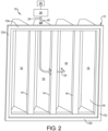
- a filter assembly 10 including a frame structure 12 that includes an upper wall 12a, a lower wall 12b and a pair of sidewalls 12c, 12d.
- the frame structure can further include a plurality of cross bars 14 extending across a downstream face of the frame structure 12.
- the frame structure 12 can be made from plastic, metal or other rigid material.
- a filter media 16 is attached to the frame structure 12 and defines a plurality of V-banks or pockets 18 (four of which are shown).
- the term pockets is intended to include pockets of any shape including V-banks that are pockets having a V-shape.
- the filter media 16 is supported in the V-bank or pocket shape by the frame structure 12.
- the filter media 16 can be pleated and can be made from any known filter media.
- a static pressure tip 20 is shown mounted to two alternative location within an aperture 22 formed in the frame structure 12.
- the aperture 22 can be formed in an upper, lower or side wall 12a-12d of the frame structure 12.
- the aperture 22 can be formed in a cross bar 14 of the frame structure 12.
- the static pressure tip 20 can include an L-shaped probe that includes a distal end with a pointed tip 20a that is directed in an upstream direction of the airflow that comes through the filer media 16 and extends into a V-bank or pocket 18.
- the probe includes a pair of openings 20b that open in a lateral direction relative to the upstream direction and are in communication with an interior bore 20c that extends to a proximal end 20d of the probe 20.
- the proximal end 20d of the probe is connected to a tube 24 that is connected to a differential pressure gauge (or measuring device) 26 such as, but not limited to a manometer.
- the static pressure tip 20 can have a mounting clamp 28 for mounting the static pressure tip 20 within the aperture 22 of the frame structure 12.
- the mounting clamp 28 can include a threaded base 30 that receives washers 32 and a nut 34 that can clamp against the frame structure 12.
- alternative clamp devices can also be used including, but not limited to, clamp plates 36 that can be press fit or otherwise secured to the proximal end of the static pressure tip 20.
- the tube24 can include a fitting 42 extending through an aperture in the filter medium 16 or frame structure 20 for directing the tube 24 to an exterior of the filter assembly 10.
- the static pressure tip 20 can be used to detect a pressure difference across a filter by comparing a measured pressure downstream of a filter to a measured pressure upstream of a filter detected by a sensor (not shown).
- the pressure difference is associated with the normal pressure reduction caused by the filter media 16 and the additional amount of blockage by filtered debris that is gathered on the filter media 16.
- a controller 40 can provide a warning signal that the filter assembly 10 needs to be changed or cleaned.
- Example embodiments are provided so that this disclosure will be thorough, and will fully convey the scope to those who are skilled in the art. Numerous specific details are set forth such as examples of specific components, devices, and methods, to provide a thorough understanding of embodiments of the present disclosure. It will be apparent to those skilled in the art that specific details need not be employed, that example embodiments may be embodied in many different forms and that neither should be construed to limit the scope of the disclosure. In some example embodiments, well-known processes, well-known device structures, and well-known technologies are not described in detail.
- first, second, third, etc. may be used herein to describe various elements, components, regions, layers and/or sections, these elements, components, regions, layers and/or sections should not be limited by these terms. These terms may be only used to distinguish one element, component, region, layer or section from another region, layer or section. Terms such as “first,” “second,” and other numerical terms when used herein do not imply a sequence or order unless clearly indicated by the context. Thus, a first element, component, region, layer or section discussed below could be termed a second element, component, region, layer or section without departing from the teachings of the example embodiments.
- spatially relative terms such as “inner,” “outer,” “beneath,” “below,” “lower,” “above,” “upper,” and the like, may be used herein for ease of description to describe one element or feature's relationship to another element(s) or feature(s) as illustrated in the figures.
- Spatially relative terms may be intended to encompass different orientations of the device in use or operation in addition to the orientation depicted in the figures. For example, if the device in the figures is turned over, elements described as “below” or “beneath” other elements or features would then be oriented “above” the other elements or features.
- the example term “below” can encompass both an orientation of above and below.
- the device may be otherwise oriented (rotated 90 degrees or at other orientations) and the spatially relative descriptors used herein interpreted accordingly.
Landscapes
- Chemical & Material Sciences (AREA)
- Chemical Kinetics & Catalysis (AREA)
- Measuring Fluid Pressure (AREA)
- Filtering Of Dispersed Particles In Gases (AREA)
Applications Claiming Priority (1)
| Application Number | Priority Date | Filing Date | Title |
|---|---|---|---|
| US18/359,022 US12539483B2 (en) | 2023-07-26 | 2023-07-26 | Air filter with integrated L-shaped pressure probe |
Publications (1)
| Publication Number | Publication Date |
|---|---|
| EP4497488A1 true EP4497488A1 (de) | 2025-01-29 |
Family
ID=91670685
Family Applications (1)
| Application Number | Title | Priority Date | Filing Date |
|---|---|---|---|
| EP24184337.4A Pending EP4497488A1 (de) | 2023-07-26 | 2024-06-25 | Luftfilter mit integriertem drucksensor |
Country Status (3)
| Country | Link |
|---|---|
| US (1) | US12539483B2 (de) |
| EP (1) | EP4497488A1 (de) |
| CN (1) | CN119367891A (de) |
Citations (3)
| Publication number | Priority date | Publication date | Assignee | Title |
|---|---|---|---|---|
| DE102017210270A1 (de) * | 2017-06-20 | 2018-12-20 | Mahle International Gmbh | Luftfilterelement mit integrierter Verunreinigungsmessung |
| US20210023494A1 (en) * | 2019-07-24 | 2021-01-28 | Carl Freudenberg Kg | Filter element having a functional space and filter arrangement having such a filter element, and method for controlling a filter system |
| EP3865199A1 (de) * | 2020-02-12 | 2021-08-18 | Carl Freudenberg KG | Filtermodul mit sensor zur bestimmung des beladungszustandes und verfahren zum bestimmen des beladungszustandes |
Family Cites Families (10)
| Publication number | Priority date | Publication date | Assignee | Title |
|---|---|---|---|---|
| CA2371729A1 (en) * | 2002-02-12 | 2003-08-12 | Thomas Hubert Vermeeren | Method of air filter diagnostic and air filter |
| US6837922B2 (en) * | 2003-03-21 | 2005-01-04 | Barney F. Gorin | Air filter sensor apparatus kit and method |
| US9120043B2 (en) * | 2006-05-30 | 2015-09-01 | 3M Innovative Properties Company | Filter sensor |
| US7726186B2 (en) * | 2006-07-19 | 2010-06-01 | Degree Controls, Inc. | Airflow sensor for filter blockage detection |
| US9104211B2 (en) * | 2010-11-19 | 2015-08-11 | Google Inc. | Temperature controller with model-based time to target calculation and display |
| US9517429B2 (en) * | 2012-11-13 | 2016-12-13 | Complete Filter Management Llc | Filtration monitoring system |
| EP3885022A1 (de) * | 2020-03-24 | 2021-09-29 | Sensirion AG | Überwachung des zustands eines filters |
| SE544762C2 (en) | 2020-12-22 | 2022-11-08 | Camfil Ab | Air filter with integrated sealed access port |
| US12594516B2 (en) * | 2021-12-23 | 2026-04-07 | Woosh Air Inc. | Frame for collapsible and foldable pleated disposable air filter with differential pressure sensor and communication capability |
| US20250090987A1 (en) * | 2023-09-20 | 2025-03-20 | Woosh Air Inc. | Air sensor tube design for improved measurement accuracy and reduction of dust related degradation |
-
2023
- 2023-07-26 US US18/359,022 patent/US12539483B2/en active Active
-
2024
- 2024-06-25 EP EP24184337.4A patent/EP4497488A1/de active Pending
- 2024-06-25 CN CN202410822607.1A patent/CN119367891A/zh active Pending
Patent Citations (3)
| Publication number | Priority date | Publication date | Assignee | Title |
|---|---|---|---|---|
| DE102017210270A1 (de) * | 2017-06-20 | 2018-12-20 | Mahle International Gmbh | Luftfilterelement mit integrierter Verunreinigungsmessung |
| US20210023494A1 (en) * | 2019-07-24 | 2021-01-28 | Carl Freudenberg Kg | Filter element having a functional space and filter arrangement having such a filter element, and method for controlling a filter system |
| EP3865199A1 (de) * | 2020-02-12 | 2021-08-18 | Carl Freudenberg KG | Filtermodul mit sensor zur bestimmung des beladungszustandes und verfahren zum bestimmen des beladungszustandes |
Also Published As
| Publication number | Publication date |
|---|---|
| CN119367891A (zh) | 2025-01-28 |
| US20250032969A1 (en) | 2025-01-30 |
| US12539483B2 (en) | 2026-02-03 |
Similar Documents
| Publication | Publication Date | Title |
|---|---|---|
| DE10140510B4 (de) | Verfahren und Vorrichtung zur Standzeitüberwachung eines Filters | |
| US7594960B2 (en) | Method and apparatus for monitoring the condition of a flexible filter | |
| AU2011201117B2 (en) | Sensor assembly with hydrophobic filter | |
| EP2098834B1 (de) | Gasmessgerät | |
| US6837922B2 (en) | Air filter sensor apparatus kit and method | |
| DE3887796T2 (de) | Anordnung zur Durchflussmengenmessung. | |
| US20070272081A1 (en) | Filter change indicator | |
| CN111163853B (zh) | 包括集成传感器组件的一次性过滤器 | |
| EP4497488A1 (de) | Luftfilter mit integriertem drucksensor | |
| WO2018200941A1 (en) | Aircraft filter system with airspeed compensation | |
| EP1933969B1 (de) | Filteranordnung | |
| KR20020001706A (ko) | 도관 내에서 유동하는 매질의 매개 변수를 측정하기 위한측정 장치 | |
| EP3885022A1 (de) | Überwachung des zustands eines filters | |
| SE544762C2 (en) | Air filter with integrated sealed access port | |
| DE202021103938U1 (de) | Filterüberwachungssystem | |
| EP3260835A1 (de) | Luftsensorsystem | |
| DE10134021A1 (de) | Vorrichtung für Turbokompressoren zum Detektieren von Instabilitäten | |
| DE4126733C2 (de) | Verfahren und Vorrichtung zum Nachweis der Verschmutzung des eintrittsseitigen Luftfilters eines Lüfters | |
| CN223827092U (zh) | 温湿度传感器 | |
| DE102021118483A1 (de) | Anordnung zur Überwachung einer Filteranlage zur Reinigung flüssiger oder gasförmiger Medien mit einem Messgerät zur Erfassung eines Differenzdrucks sowie ein Verfahren zum Betreiben einer solchen Anordnung | |
| JPH0353687Y2 (de) | ||
| DE102021118481A1 (de) | Anordnung zur Differenzdruckmessung sowie Verwendung einer solchen Anordnung | |
| CN110595974A (zh) | 一种颗粒浓度监测装置及方法 |
Legal Events
| Date | Code | Title | Description |
|---|---|---|---|
| PUAI | Public reference made under article 153(3) epc to a published international application that has entered the european phase |
Free format text: ORIGINAL CODE: 0009012 |
|
| STAA | Information on the status of an ep patent application or granted ep patent |
Free format text: STATUS: THE APPLICATION HAS BEEN PUBLISHED |
|
| AK | Designated contracting states |
Kind code of ref document: A1 Designated state(s): AL AT BE BG CH CY CZ DE DK EE ES FI FR GB GR HR HU IE IS IT LI LT LU LV MC ME MK MT NL NO PL PT RO RS SE SI SK SM TR |
|
| STAA | Information on the status of an ep patent application or granted ep patent |
Free format text: STATUS: REQUEST FOR EXAMINATION WAS MADE |
|
| 17P | Request for examination filed |
Effective date: 20250729 |
|
| STAA | Information on the status of an ep patent application or granted ep patent |
Free format text: STATUS: EXAMINATION IS IN PROGRESS |
|
| 17Q | First examination report despatched |
Effective date: 20250918 |
|
| GRAP | Despatch of communication of intention to grant a patent |
Free format text: ORIGINAL CODE: EPIDOSNIGR1 |
|
| STAA | Information on the status of an ep patent application or granted ep patent |
Free format text: STATUS: GRANT OF PATENT IS INTENDED |