EP4497402A2 - Systeme zur verstärkung eines wirbelkörpers - Google Patents
Systeme zur verstärkung eines wirbelkörpers Download PDFInfo
- Publication number
- EP4497402A2 EP4497402A2 EP24218618.7A EP24218618A EP4497402A2 EP 4497402 A2 EP4497402 A2 EP 4497402A2 EP 24218618 A EP24218618 A EP 24218618A EP 4497402 A2 EP4497402 A2 EP 4497402A2
- Authority
- EP
- European Patent Office
- Prior art keywords
- sheath
- lock
- shaft
- hub
- introducer device
- Prior art date
- Legal status (The legal status is an assumption and is not a legal conclusion. Google has not performed a legal analysis and makes no representation as to the accuracy of the status listed.)
- Pending
Links
Images


Classifications
-
- A—HUMAN NECESSITIES
- A61—MEDICAL OR VETERINARY SCIENCE; HYGIENE
- A61B—DIAGNOSIS; SURGERY; IDENTIFICATION
- A61B17/00—Surgical instruments, devices or methods
- A61B17/16—Instruments for performing osteoclasis; Drills or chisels for bones; Trepans
- A61B17/17—Guides or aligning means for drills, mills, pins or wires
- A61B17/1739—Guides or aligning means for drills, mills, pins or wires specially adapted for particular parts of the body
- A61B17/1757—Guides or aligning means for drills, mills, pins or wires specially adapted for particular parts of the body for the spine
-
- A—HUMAN NECESSITIES
- A61—MEDICAL OR VETERINARY SCIENCE; HYGIENE
- A61B—DIAGNOSIS; SURGERY; IDENTIFICATION
- A61B17/00—Surgical instruments, devices or methods
- A61B17/16—Instruments for performing osteoclasis; Drills or chisels for bones; Trepans
- A61B17/1642—Instruments for performing osteoclasis; Drills or chisels for bones; Trepans for producing a curved bore
-
- A—HUMAN NECESSITIES
- A61—MEDICAL OR VETERINARY SCIENCE; HYGIENE
- A61B—DIAGNOSIS; SURGERY; IDENTIFICATION
- A61B10/00—Instruments for taking body samples for diagnostic purposes; Other methods or instruments for diagnosis, e.g. for vaccination diagnosis, sex determination or ovulation-period determination; Throat striking implements
- A61B10/02—Instruments for taking cell samples or for biopsy
- A61B10/0233—Pointed or sharp biopsy instruments
- A61B10/025—Pointed or sharp biopsy instruments for taking bone, bone marrow or cartilage samples
-
- A—HUMAN NECESSITIES
- A61—MEDICAL OR VETERINARY SCIENCE; HYGIENE
- A61B—DIAGNOSIS; SURGERY; IDENTIFICATION
- A61B17/00—Surgical instruments, devices or methods
- A61B17/16—Instruments for performing osteoclasis; Drills or chisels for bones; Trepans
- A61B17/1662—Instruments for performing osteoclasis; Drills or chisels for bones; Trepans for particular parts of the body
- A61B17/1671—Instruments for performing osteoclasis; Drills or chisels for bones; Trepans for particular parts of the body for the spine
-
- A—HUMAN NECESSITIES
- A61—MEDICAL OR VETERINARY SCIENCE; HYGIENE
- A61B—DIAGNOSIS; SURGERY; IDENTIFICATION
- A61B17/00—Surgical instruments, devices or methods
- A61B17/34—Trocars; Puncturing needles
- A61B17/3472—Trocars; Puncturing needles for bones, e.g. intraosseus injections
-
- A—HUMAN NECESSITIES
- A61—MEDICAL OR VETERINARY SCIENCE; HYGIENE
- A61B—DIAGNOSIS; SURGERY; IDENTIFICATION
- A61B17/00—Surgical instruments, devices or methods
- A61B17/56—Surgical instruments or methods for treatment of bones or joints; Devices specially adapted therefor
- A61B17/58—Surgical instruments or methods for treatment of bones or joints; Devices specially adapted therefor for osteosynthesis, e.g. bone plates, screws or setting implements
- A61B17/88—Osteosynthesis instruments; Methods or means for implanting or extracting internal or external fixation devices
- A61B17/8802—Equipment for handling bone cement or other fluid fillers
- A61B17/8805—Equipment for handling bone cement or other fluid fillers for introducing fluid filler into bone or extracting it
- A61B17/8811—Equipment for handling bone cement or other fluid fillers for introducing fluid filler into bone or extracting it characterised by the introducer tip, i.e. the part inserted into or onto the bone
-
- A—HUMAN NECESSITIES
- A61—MEDICAL OR VETERINARY SCIENCE; HYGIENE
- A61B—DIAGNOSIS; SURGERY; IDENTIFICATION
- A61B17/00—Surgical instruments, devices or methods
- A61B17/56—Surgical instruments or methods for treatment of bones or joints; Devices specially adapted therefor
- A61B17/58—Surgical instruments or methods for treatment of bones or joints; Devices specially adapted therefor for osteosynthesis, e.g. bone plates, screws or setting implements
- A61B17/88—Osteosynthesis instruments; Methods or means for implanting or extracting internal or external fixation devices
- A61B17/8802—Equipment for handling bone cement or other fluid fillers
- A61B17/8805—Equipment for handling bone cement or other fluid fillers for introducing fluid filler into bone or extracting it
- A61B17/8816—Equipment for handling bone cement or other fluid fillers for introducing fluid filler into bone or extracting it characterised by the conduit, e.g. tube, along which fluid flows into the body or by conduit connections
-
- A—HUMAN NECESSITIES
- A61—MEDICAL OR VETERINARY SCIENCE; HYGIENE
- A61B—DIAGNOSIS; SURGERY; IDENTIFICATION
- A61B17/00—Surgical instruments, devices or methods
- A61B17/56—Surgical instruments or methods for treatment of bones or joints; Devices specially adapted therefor
- A61B17/58—Surgical instruments or methods for treatment of bones or joints; Devices specially adapted therefor for osteosynthesis, e.g. bone plates, screws or setting implements
- A61B17/88—Osteosynthesis instruments; Methods or means for implanting or extracting internal or external fixation devices
- A61B17/8802—Equipment for handling bone cement or other fluid fillers
- A61B17/8805—Equipment for handling bone cement or other fluid fillers for introducing fluid filler into bone or extracting it
- A61B17/8819—Equipment for handling bone cement or other fluid fillers for introducing fluid filler into bone or extracting it characterised by the introducer proximal part, e.g. cannula handle, or by parts which are inserted inside each other, e.g. stylet and cannula
-
- A—HUMAN NECESSITIES
- A61—MEDICAL OR VETERINARY SCIENCE; HYGIENE
- A61B—DIAGNOSIS; SURGERY; IDENTIFICATION
- A61B17/00—Surgical instruments, devices or methods
- A61B17/56—Surgical instruments or methods for treatment of bones or joints; Devices specially adapted therefor
- A61B17/58—Surgical instruments or methods for treatment of bones or joints; Devices specially adapted therefor for osteosynthesis, e.g. bone plates, screws or setting implements
- A61B17/88—Osteosynthesis instruments; Methods or means for implanting or extracting internal or external fixation devices
- A61B17/8802—Equipment for handling bone cement or other fluid fillers
- A61B17/8805—Equipment for handling bone cement or other fluid fillers for introducing fluid filler into bone or extracting it
- A61B17/8822—Equipment for handling bone cement or other fluid fillers for introducing fluid filler into bone or extracting it characterised by means facilitating expulsion of fluid from the introducer, e.g. a screw pump plunger, hydraulic force transmissions, application of vibrations or a vacuum
-
- A—HUMAN NECESSITIES
- A61—MEDICAL OR VETERINARY SCIENCE; HYGIENE
- A61B—DIAGNOSIS; SURGERY; IDENTIFICATION
- A61B17/00—Surgical instruments, devices or methods
- A61B17/56—Surgical instruments or methods for treatment of bones or joints; Devices specially adapted therefor
- A61B17/58—Surgical instruments or methods for treatment of bones or joints; Devices specially adapted therefor for osteosynthesis, e.g. bone plates, screws or setting implements
- A61B17/88—Osteosynthesis instruments; Methods or means for implanting or extracting internal or external fixation devices
- A61B17/885—Tools for expanding or compacting bones or discs or cavities therein
- A61B17/8852—Tools for expanding or compacting bones or discs or cavities therein capable of being assembled or enlarged, or changing shape, inside the bone or disc
- A61B17/8855—Tools for expanding or compacting bones or discs or cavities therein capable of being assembled or enlarged, or changing shape, inside the bone or disc inflatable, e.g. kyphoplasty balloons
-
- A—HUMAN NECESSITIES
- A61—MEDICAL OR VETERINARY SCIENCE; HYGIENE
- A61B—DIAGNOSIS; SURGERY; IDENTIFICATION
- A61B17/00—Surgical instruments, devices or methods
- A61B17/00234—Surgical instruments, devices or methods for minimally invasive surgery
- A61B2017/00292—Surgical instruments, devices or methods for minimally invasive surgery mounted on or guided by flexible, e.g. catheter-like, means
- A61B2017/003—Steerable
- A61B2017/00305—Constructional details of the flexible means
- A61B2017/00314—Separate linked members
-
- A—HUMAN NECESSITIES
- A61—MEDICAL OR VETERINARY SCIENCE; HYGIENE
- A61B—DIAGNOSIS; SURGERY; IDENTIFICATION
- A61B18/00—Surgical instruments, devices or methods for transferring non-mechanical forms of energy to or from the body
- A61B2018/00315—Surgical instruments, devices or methods for transferring non-mechanical forms of energy to or from the body for treatment of particular body parts
- A61B2018/00339—Spine, e.g. intervertebral disc
Definitions
- a common source of back pain is a vertebral compression fracture in which a weakened or injured vertebral body loses height or collapses.
- the weakening of the vertebral body may be due to acute injury or, more often, degenerative changes such as osteoporosis.
- the compression fractures often appear on lateral radiographs as wedge deformities with greater loss of height anteriorly.
- a vertebroplasty includes delivering curable material, for example a bone cement, within an interior of the vertebral body. The material interdigitates with cancellous bone and cures to stabilize the vertebral body.
- a kyphoplasty includes creating a cavity within the interior of the vertebral body by compressing the cancellous bone with an expandable member such as a balloon, and delivering the curable material into the cavity. The expandable member may facilitate elevating or restoring the height of the vertebral body.
- Accessing the interior of the vertebral body often includes percutaneously placing an access cannula through a pedicle of the vertebra. Owing to the structure of the vertebra, accessing a location on the contralateral side of the vertebral body is not especially feasible with straight instrumentation. As such, one existing kyphoplasty technique employs a bipedicular approach in which two access cannulas are placed, followed by two expandable members each positioned ipsilaterally within the interior of the vertebral body. The bipedicular approach undesirably requires twice the trauma to tissue, and often requires twice the instrumentation.
- a first aspect of the present disclosure is directed to method of augmenting a vertebral body.
- a distal end of an access cannula is positioned within the vertebral body such that a lumen of the access cannula provides access to an interior region of the vertebral body along a longitudinal axis.
- a shaft of the introducer device and the sheath are directed to within the access cannula such that the distal portion of the introducer device and the flexible region of the sheath remains within the access cannula.
- the introducer device is in an unconstrained state in which a pulling element is at a first tension. Thereafter, an input to an actuator to move the introducer device from the unconstrained state to a constrained state in which the pulling element is at a second tension greater than the first tension.
- the access cannula prevents the distal portion of the shaft and the distal portion of the sheath from assuming a curve from the longitudinal axis. Thereafter, the introducer device and the sheath device are advanced relative to the access cannula with the introducer device in the constrained state such that the distal portion of the introducer device and the distal portion of the sheath assume the curve within the vertebral body with advancement beyond the distal end of the access cannula.
- the distal portion of the introducer device and the flexible region of the sheath and configured to plunge through cancellous bone within the vertebral body while assuming the curve.
- a distal end of the sheath Prior to plunging, a distal end of the sheath may be positioned in registration with the distal end of the access cannula.
- Indicia disposed on the sheath may be aligned with a hub of the access cannula so as to position the distal end of the distal portion in registration with the distal end of the access cannula.
- another input may be provided to the actuator to move or return the introducer device from the constrained state to the unconstrained state.
- the introducer device may be removed from the sheath device.
- the pulling element being at the first tension in the unconstrained state provides for removal of the introducer device from the sheath with the flexible region of the sheath remaining curved within the vertebral body.
- the cancellous bone of the vertebral body may at least partially support the curve. Should the curve not be positioned in the desired orientation, for example, the introducer device may be redirected through the sheath device.
- the system includes a spacer lock defining an aperture and including legs defining at least one slot.
- the legs of the spacer lock may be engaged with a cannula hub of the access cannula such that the aperture is aligned with the lumen.
- a sheath hub of the sheath is disposed within the slot(s).
- a treatment device may be directed through the aperture to within the sheath.
- the treatment device is flexible to bend along the curve of the flexible region of the sheath disposed within the vertebral body.
- the sheath hub may be proximally moved within the slot(s) of the spacer lock with corresponding movement of the sheath, thereby exposing the treatment device at a target location within the vertebral body.
- Augmentation of tissue of the vertebral body may be performed at the target location with the treatment device.
- the treatment device may be one of a cavity-forming device configured to displace tissue, an electrode probe configured to ablate tissue, a drill device for cutting tissue, and a tissue capturing device for tissue biopsy, among others.
- An input may be provided to the lock actuator of the spacer lock to disengage the lock actuator from a shaft of the treatment device.
- the treatment device may be moved within the aperture of the spacer lock to selectively adjust a position of the treatment device relative to the access cannula.
- the input may then be removed to reengage the lock mechanism and the shaft of the treatment device, thereby preventing further movement of the treatment device relative to the access cannula.
- a second aspect of the present disclosure is directed to system of augmenting a vertebral body.
- An access cannula includes a cannula hub, and a cannula shaft extending from the cannula hub.
- the cannula shaft includes a distal end positionable within the vertebral body and defining a lumen along a longitudinal axis.
- An introducer device includes an actuator, a shaft, and a pulling element. The actuator configured to receive an input from a user.
- the shaft includes a proximal portion that is rigid, and a distal portion that is articulable.
- the spacer lock is configured to rest upon the engagement surface under influence of gravity without an additional coupling mechanism.
- the cannula hub may include handles spaced proximal to the engagement surface. The legs and the handles are positioned in an interlocking arrangement such that opposing aspects of at least one of the handles may prevent rotation of the spacer lock relative to the access cannula.
- the sheath hub being disposed within the slots prevents rotation of the sheath relative to the spacer lock, and optionally relative to the access cannula.
- the spacer lock of the sixth aspect may be included with the system according to the second aspect, and optionally, any of its corresponding implementations.
- a ninth aspect of the disclosure is directed to a sheath device for a system for augmenting a vertebral body.
- a sheath includes a proximal portion extending from a sheath hub along a longitudinal axis and comprising metal, and a distal portion comprising polymeric material.
- the proximal portion is coupled to the distal portion at an interface including a plurality of protrusions on each of the proximal portion and the distal portion configured to engage one another and provide a constant inner diameter and a constant outer diameter across the interface.
- the sheath of the ninth aspect may be included with the systems according to the second, fourth, fifth, sixth and seventh aspects, and optionally, any of their corresponding implementations.
- a tenth aspect of the disclosure is directed to a system for augmenting a vertebral body.
- An access cannula includes a cannula hub, and a cannula shaft extending from the cannula hub.
- the cannula shaft includes a distal end positionable within the vertebral body and defining a lumen along a longitudinal axis.
- An introducer device includes an actuator, a shaft, and a pulling element.
- the actuator configured to receive an input from a user.
- the shaft includes a proximal portion that is rigid, and a distal portion.
- the pulling element is coupled to the actuator and to the distal portion.
- the indicia of the tenth aspect may be included with the systems according to the second, fourth, fifth, sixth, seventh and ninth aspects, and optionally, any of their corresponding implementations.
- an electrode shaft of an electrode probe is directed through the sheath.
- a probe may be exposed beyond the distal end of the sheath and within the bore. The probe is operated to ablate tissue within the vertebral body.
- An expandable member is directed through the sheath to be exposed beyond the distal end of the sheath and within the bore. The expandable member may be directed into the bore before or after ablation of the tissue.
- the expandable member may be inflated to provide a cavity within the vertebral body.
- the expandable member is deflated, and then removed from the sheath. Curable material through the sheath to within the cavity of the vertebral body.
- a twelfth aspect of the present disclosure is directed to method of augmenting a vertebral body.
- a distal end of an access cannula is positioned within the vertebral body to provide access to an interior region of the vertebral body along a longitudinal axis.
- a shaft of an introducer device and a sheath is directed beyond the access cannula.
- the introducer device is operated to cause the distal portion of the shaft and the flexible region of the sheath to assume a curve within the interior region of the vertebral body.
- the introducer device is removed from the sheath device with the flexible region of the sheath remaining in the curve.
- a biopsy device is directed through the sheath device and capture a tissue sample within the vertebral body. The biopsy device is removed from the sheath device.
- the biopsy device of the method according to the twelfth aspect may be included with the systems according to the second, fourth, fifth, sixth, seventh, ninth, tenth aspects and eleventh, and optionally, any of their corresponding implementations.
- methods and systems according to the first through thirteenth aspects may be operable to augment non-osseous anatomy, for example, ear, nose, and throat (ENT) or other difficult to access anatomy with straight instrumentation.
- non-osseous anatomy for example, ear, nose, and throat (ENT) or other difficult to access anatomy with straight instrumentation.
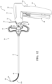
- Figure 1 shows a system 30 for augmenting anatomy.
- the system 30 includes an introducer device 32, an access cannula 34, and a sheath device 36.
- the system 30 may further include a treatment device (e.g., a cavity-forming device 38) and a spacer lock 40.
- a treatment device e.g., a cavity-forming device 38
- a spacer lock 40 e.g., a spacer lock 40.
- the certain components of the system 30 are removably couplable to and/or deployable through one another in a manner that facilitates off-axis access within the anatomy of interest.
- An exemplary procedure to be described throughout the present disclosure is augmentation of vertebral body for performing a vertebroplasty, kyphoplasty, ablation, biopsy, drilling and/or other related procedure.
- the system 30 may be configured to augment other bones of the body, for example, a cranium, a long bone, and an ilium.
- the system 30 may be configured to augment non-osseous anatomy, for example, ear, nose, and throat (ENT) or other difficult to access anatomy with straight instrumentation.
- ENT ear, nose, and throat
- the access cannula 34 includes a cannula hub 42, and a cannula shaft 44 extending from the cannula hub 42.
- the cannula shaft 44 includes a proximal end 46 coupled to the cannula hub 42, and a distal end 48 opposite the proximal end 46.
- the cannula shaft 44 may be straight and define a lumen (not identified) extending between the proximal and distal ends 46, 48 such that the cannula shaft 44 is tubular in shape.
- the cannula shaft 44 may comprise or be formed from biocompatible materials with sufficient mechanical properties to maintain integrity as the cannula shaft 44 is driven through the pedicle of the vertebra.
- the system 30 may include a trocar (not shown) removably positioned within the cannula shaft 44 during placement of the distal end 48 of the cannula shaft 44 into the vertebral body.
- the trocar may include a length slightly greater than a length of the cannula shaft 44 such that a sharp tip of the trocar pierces the cortical bone of the cortical rim, and the trocar prevents coring of tissue within the lumen of the cannula shaft 44.
- the trocar is removed.
- the access cannula 34 provides a working channel to within the interior region of the vertebral body along a longitudinal axis defined by the cannula shaft 44.
- the cannula hub 42 is exposed above the tissue overlying the vertebra, and certain components of the system 30 are configured to be directed through the working channel of the access cannula 34.
- the introducer device 32 - to which the sheath device 36 may be removably coupled - may be directed within or through the access cannula 34.
- the introducer device 32 may be actuated to form a curved path within the vertebral body with advancement of the introducer device 32 beyond the access cannula 34.
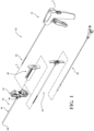
- the introducer device 32 includes an actuator 50, and a shaft 52 extending from the actuator 50.
- the actuator 50 is configured to receive an input from a practitioner or user to actuate the introducer device 32 from an unconstrained state in which the shaft 52 of the introducer device 32 is straight and may be inserted or removed from the cannula shaft 44 of the access cannula 34, respectively.
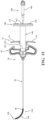
- the introducer device 32 is actuated from the unconstrained state to a constrained state in which a distal portion 82 of the shaft 52 is urged away from the longitudinal axis.
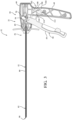
- Figures 2 and 3 show the introducer device 32 in the unconstrained state
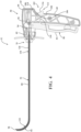
- Figure 4 shows the introducer device 32 in the constrained state.
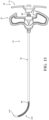
- the actuator 50 includes a housing 56, and a control member 58 movably coupled to the housing 56.
- the illustrated implementation shows the housing 56 and the control member 58 in a "pistol-grip" arrangement in which a handle 60 of the housing 56 is configured to rest in a palm of a hand of the practitioner, and the control member 58 configured to be pivotably pulled towards or released away from the handle 60 with one or more fingers of the hand of the practitioner.
- a frame 62 may be integrally formed with and extend distal to (or forward of) the handle 60 in a generally L-shaped arrangement.
- distal or distally refers to a direction away from the practitioner, and proximal or proximally refers to a direction towards the practitioner.
- the housing 56 may comprise mirrored housing shells 64, 66 joined together, which may be manufactured from polymers, metals, composites, and combinations thereof.
- each of the housing shells 64, 66 may be injection molded so as to be low cost and disposable after a single use.
- the housing shells 64, 66 may at least partially define an interior of the housing 56 sized and shaped to accommodate several components of the actuator 50 to be described.
- the frame 62 of the housing 56 may include shoulders 68 defining a slot 70 therebetween.
- One of the housing shells 64 includes one of the shoulders 68, and the other one of the housing shells 66 includes the other one of the shoulders 68 such that the shoulders 68 are generally positioned at the three and six o'clock positions.
- the slot 70 is oriented vertically between the shoulders 68 and sized to receive a hub 72 of the sheath device 36, as best shown in Figure 2 . More particularly, the hub 72 of the sheath device 36 includes flats 74 (see also Figure 7 ) positioned adjacent a respective one of the shoulders 68 when the hub 72 is removably and slidably received within the slot 70 of the frame 62.
- the resulting arrangement prevents rotation of the sheath device 36 relative to the introducer device 32. As such, a hand of the practitioner is freed from separately having to maintain the rotational position of the sheath device 36 as he or she manipulates the introducer device 32 to a desired orientation.
- the resulting arrangement may further facilitate ease with retraction and removal of the introducer device 32 from the sheath device 36 after deployment within the vertebral body in a manner to be further explained. Still further, the resulting arrangement may prevent or twisting or kinking of the sheath device 36 as the practitioner manipulates the introducer device 32 in the constrained state against resistance of the cancellous bone in the vertebral body.
- the hub 72 of the sheath device 36 may further include wings 76 positioned between the flats 74 so as to be aligned with the slot 70 of the frame 62 when the hub 72 is removably and slidably received within the slot 70 of the frame 62.
- the wings 76 may provide not only ergonomic surfaces for one or more fingers of the physician, but also a visual indication as to a direction of curvature of the introducer device 32 once actuated to the constrained state. Further indication of the direction of curvature of the introducer device 32 once actuated to the constrained state may be provided elsewhere on the housing 56.
- indicia 78 such as a line may be positioned on a proximal side of the frame 62.
- the indicia 78 and an upper one of the wings 76 may function as rear and forward sights, respectively - which are already within his or her field of view over the surgical site, to provide intuitive guidance to the practitioner. Additionally or alternatively, the indicia 78 may be positioned on one or both the wings 76 of the sheath device 36. The indicia 78 may be on an upper one of the wings 76 corresponding to a direction of curvature of the flexible distal portion 82 of the sheath device 36, as generally shown in Figure 7 .
- the indicia 78 being positioned on the wings 76 provide visual indication as to the direction of curvature of the flexible distal portion 82 within the vertebral body.
- the indicia 78 may provide further visual indication as to the direction that subsequent components directed through the sheath device 36 may be extend from the flexible distal portion 82.
- the proximal side of the frame 62 may include a flattened surface 65 (see Figure 4 ) configured to receive an impact force from a surgical mallet or the like.
- a flattened surface 65 (see Figure 4 ) configured to receive an impact force from a surgical mallet or the like.
- the flattened surface 65 may be positioned proximal to the handle 60 to define a proximal end of the introducer device 32.
- the flattened surface 65 may be at least substantially planar, and further may be at least substantially circular.
- the circularity of the flattened surface 65 may corresponding in shape and size to a head of the mallet, thus providing an intuitive indication of the appropriate location to impact the introducer device 32 with the surgical mallet.
- the user may firmly support the handle 60 in one hand while impacting the flattened surface 65 of the frame 60 with the mallet being held in the other hand.
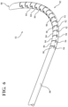
- the shaft 52 of the introducer device 32 includes a rigid proximal portion 80 and the flexible distal portion 82.
- the proximal portion 80 of the shaft 52 extends through a bore of the frame 62 to a position within the interior of the handle 60.
- the proximal portion 80 of the shaft 52 may be axially and rotationally fixed relative to the actuator 50.
- a retaining block 85 may be disposed within the interior of the handle 60 with a proximal end of the proximal portion 80 of the shaft 52 being secured to the retaining block 85.
- the proximal portion 80 may be formed from rigid material(s) with sufficient mechanical properties to avoid more than minimal flexure.
- the distal portion 82 extends from the proximal portion 80.
- a transition between the proximal portion 80 and the distal portion 82 may be defined by a first of a series of geometries within the shaft 52.
- the series of geometries may provide a series of interconnected segments 84.
- the interconnected segments 84 may be of unitary construction. In other words, the segments 84 may not be discrete links, but rather subportions of the distal portion 82 configured to articulate relative to one another.
- the shaft 52 including the proximal and distal portions 80, 82 may comprise or be formed from a single piece of metal. In one implementation, the geometries may be laser cut into the single piece of metal.
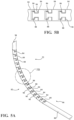
- the geometries may take the form of slots 86 defined within an upper side of the distal portion 82.
- the slots 86 may be T-shaped as shown in Figure 5B .
- the geometries may further include protrusions 88 corresponding to the shape of the slots 86.
- the protrusions 88 may also be T-shaped.
- the slots 86 and protrusions 88 may be disposed on an upper or concave side of the distal portion 82, as generally appreciated from Figure 5A .
- first slits 90 extending from the slots 86 are first slits 90, and the first slits 90 extend about a portion of the outer diameter of the distal portion 82.
- the first slits 90 may be oriented transverse to the longitudinal axis.
- the first slits 90 of the illustrated implementation extend about a majority of the outer diameter.
- Further geometries may be disposed on a lower or convex side of the distal portion 82, and those geometries may interconnect the segments 84.
- first slits 90 terminate at second slits 92 to define spine sections 94 between opposing pairs of the second slits 92.
- the second slits 92 may be angled relative to the first slits 90, for example, at right angles such that the second slits 92 are oriented parallel to the longitudinal axis of the distal portion 82.
- the spine sections 94 are configured to flex. The flexure of the spine sections 94 is at least sufficient to permit the protrusions 88 to move within the slots 86 into contact with the adjacent edges as previously described.
- the resulting arrangement provides for relative movement of the segments 84 and, in the aggregate, articulation of the distal portion 82 over its length.
- the extent of articulation or curvature of the distal portion 82 may be selectively controlled through selective tensioning of the pulling element 54.
- the angle of articulation or curvature may be designed within the range of approximately 50 to 150 degrees, and more particularly within the range of approximately 65 to 125 degrees, and even more particularly within the range of approximately 80 to 100 degrees.
- Figures 4 , 5A and 6 show the distal portion 82 oriented at an angle of approximately 90 degrees relative to the proximal portion 80.
- the reverse configuration is contemplated in which the slots 86 and protrusions 88 may be disposed on the lower or concave side of the distal portion 82, and the first and second slits 90, 92 are disposed on the upper or concave side of the distal portion 82.
- the user may rotate the introducer device 32 during or after deployment of the distal portion 82 within the vertebral body in order to steer the distal portion 82 to a target location.
- the distal portion 82 including the segments 84 endure torqueing as the introducer device 32 is rotated.
- the segments 84 of the distal portion 82 may advantageously be designed to achieve the desired steerability while providing compliance or flexibility of the segments 84 to handle the torque.
- lateral aspects of the slots 86 and/or lateral aspects of the protrusions 88 may be sized to define a gap of a specific size such that adjacent segments 84 may be free to rotate slightly relative to one another prior to the complementary lateral aspects engage one another.
- the "rotational play" between the adjacent segments 84 may limit torqueing on the segments 84 during initial rotation of the introducer device 32. Once the complementary lateral aspects engage one another, the segments 84 become rigid in nature and preserve steerability with subsequent rotation of the introducer device 32.
- proximal segments 84 endure more torque than more distal segments 84.
- the counteracting forces from the cancellous bone on a distal end 98 of the shaft 52 result in heightened torque on a proximal-most one of the segments 84 ( i.e., adjacent the proximal portion 80) with further rotation of the introducer device 32.
- the introducer device 32 of the present disclosure advantageously contemplates varying the design of individual segments 84 to account for the gradient of anticipated torque along a length of the distal portion 82.
- the aforementioned gaps between the complementary lateral aspects of the slots 86 and the protrusions 88 may decrease more distally along a length of the distal portion 82.
- the arrangement results in more distal adjacent segments 84 being more rigid in function relative to more proximal adjacent segments 84 during rotation of the introducer device 32.
- the spine sections 94 may be of varying widths along the length of the distal portion 82. More particularly, the width of the spine sections 94 may progressively decrease distally along the length of the distal portion 82 such that the spine sections 94 of the proximal-most segments 84 are wider to endure greater torque.
- the reverse configurations of the gaps and/or the spine sections 94 are contemplated as well.
- the pulling element 54 is coupled to the actuator 50 and the shaft 52, and more particularly the distal portion 82 of the shaft 52.
- the pulling element 54 includes a proximal end coupled to the control member 58 of the actuator 50.
- the pulling element 54 may be secured to the control member 58 with an interference connector 96, for example a ferrule, nut, swaged sleeve, clamp, or other suitable connector.
- the connector 96 may be sized to movably ride within a slot defined by complementary pockets in each of the housing shells 64, 66.
- An input to the control member 58 e.g., pulled towards the handle 60 urges the connector 96 proximally within the slot, thereby tensioning the pulling element 54.
- the pulling element 54 includes a distal end coupled to the shaft 52 at or near its distal end 98.
- the pulling element 54 extends through a lumen 100 of the shaft 52, and may be joined at or near the distal end 98 of the shaft 52 through brazing, welding, adhesive, interference fit, or other suitable joining process.
- the distal end of the pulling element 54 may be coterminous with the distal end 98 of the shaft 52.
- the pulling element 54 may be monolithic in construction and comprise or be formed from a metal, polymer, composite, or combination thereof.
- the pulling element 54 may be a wire rope, a wire, a rod, and the like, of solid or hollow construction.
- the pulling element 54 may be coupled to the shaft 52 with a hypotube (not shown).
- the hypotube may have an inner diameter slightly greater than an outer diameter of the pulling element 54, and an outer diameter slightly less than an inner diameter of the shaft 52.
- the hypotube may have a length sized to be disposed within a distalmost of the interconnected segments 84. In one example, the hypotube has a length of approximately three millimeters.
- the hypotube may be secured over a distal end of the pulling element 54, for example, by crimping.
- the outer surface of the hypotube may then be welded or otherwise secured to the inner surface of the shaft 52.
- the hypotube being crimped onto the pulling element 54 may preserve the tensile strength of the pulling element 54 relative to implementations where welding may anneal the pulling element 54 with corresponding reduction in tensile strength.
- the pulling element 54 is configured to be selectively tensioned to alter the extent of the articulation or curvature of the distal portion 82.
- minimal or zero tension may be exerted on the pulling element 54, also referred to herein as a first tension. It should be appreciated that some minimal tension may be on the pulling element 54 in the unconstrained state.
- the input to the control member 58 increases the tension on the pulling element 54 to move the introducer device 32 to the constrained state, also referred to herein as a second tension. The second tension is greater than the first tension.
- the actuator 50 may be locked with the introducer device 32 in the constrained state.
- the actuator 50 may include a locking mechanism 102 for operably coupling the housing 56 and the control member 58 and configured to permit selective locking of the control member 58.
- the locking mechanism 102 of the implementation shown in Figures 3 and 4 provides for simplified, cost-effective construction and intuitive operation.
- Each of the shells 64, 66 includes the handle 60 defines a proximal opening 104 and includes a ramp 106 and a retention feature 108 adjacent the ramp 106.
- the ramp 106 and the retention feature 108 may define an upper portion of the proximal opening 104, and the proximal opening 104 may be ergonomically positioned on the handle 60 to be easily accessible by the thumb of the practitioner when holding the actuator 50 of the introducer device 32 (see Figure 2 ).
- the locking mechanism 102 may further include an arm 110 coupled to and extending from the control member 58 in a direction opposite the control surface 59. Figures 3 and 4 show the arm 110 extending proximally from the control member 58 towards the handle 60.
- a lock head 112 is at the end of the arm 110.
- the arm 110 and lock head 112 are arranged and dimensioned such that, as the control member 58 is pivoted towards the handle 60 as the actuator 50 is actuated, the lock head 112 moves towards and assumes a position within the proximal opening 104.
- the lock head 112 is configured to releasably engage the retention feature 108 of the handle 60.
- the arm 110 is resilient and configured to deflect as the lock head 112 moves along the ramp 106 of the handle 60. More particularly, as the control member 58 is pivoted towards the handle 60, an upper surface of the lock head 112 contacts the ramp 106. The interference between the lock head 112 and the ramp 106 results in the arm 110 deflecting downwardly with further pivoting of the control member 58 with force sufficient to overcome the interference.
- a notch 114 on the lock head 112 moves past the ramp 106, and the dimensions of the notch 114 permit the arm 110 to resiliently return to an original state in which the notch 114 engages the retention feature 108, as shown in Figure 4 .
- the resilient return of the arm 110 is sudden, and the lock head 112 contacting the retention feature 108 may result in an audible and/or tactile feedback to the practitioner.
- the actuator 50 including the control member 58, the handle 60, the arm 110, and the lock head 112 are formed from plastic
- the plastic-on-plastic impact may make a sound audible to the practitioner.
- the locking mechanism 102 of the present disclosure provides for a low-cost design that is more easily manufacturable than, for example, a ratchet mechanism.
- the other suitable mechanism for selectively locking the introducer device 32 in the constrained state are contemplated.
- One suitable example is described in the commonly-owned United States Patent No. 9,839,443 , hereby incorporated by reference in its entirety, in which a ratchet is configured to be selectively locked one of a plurality of positions corresponding to different tensions on the pulling element and different angles of curvature of the steering instrument.
- the lock head 112 extends through the proximal opening 104.
- the lock head 112 includes a release surface 116 positioned proximal to the proximal opening 104 so as to be engageable by the thumb of the practitioner.
- the workflow includes the step of removing the introducer device 32 from the sheath device 36.
- the introducer device 32 may be operably coupled to the sheath device 36 when deployed into the vertebral body, and the workflow may include the step of removing the introducer device 32 from the sheath device 36. Subsequently, components of the system 30 may be deployed through the sheath device 36.
- the sheath device 36 includes the hub 72, and a sheath 118 extending from the hub 72.
- the hub 72 may include a fitting 120 in communication with a lumen 122 of the sheath 118 and configured to be removably coupled with another component of the system 30.
- One exemplary fitting is a Luer fitting.
- At least a region of the sheath 118 is flexible and configured to conform to the shaft 52, and more particularly to the distal portion 82 of the shaft 52 as the introducer device 32 moved from the constrained state to the unconstrained state.
- the flexible region 124 extends from a proximal portion 126 of the sheath 118.
- the proximal portion 126 is coupled to and extends distally from the hub 72, and the proximal portion 126 may be flexible or rigid.
- the proximal portion 126 is rigid and comprise or be formed from biocompatible materials with sufficient mechanical properties to maintain integrity as the sheath device 36 is retracted and advanced in a manner to be described.
- One exemplary material is stainless steel.
- the flexible region 124 may be coupled to or integrally formed with the proximal portion 126.
- the flexible region 124 may be a separate component joined with the proximal portion 126 at a lap joint.
- the flexibility of the flexible region 124 may be due to a helical pattern extending between opposing ends 128 of the flexible region 124.
- the helical pattern may be formed by laser cutting or other suitable manufacturing process, and it is to be understood that a helix is one exemplary geometry.
- Each of the flexible region 124 and the proximal portion 126 defines a portion of the lumen 122.
- the flexible region 124 of the sheath 118 is axially aligned with the distal portion 82 of the shaft 52.
- the flexible region 124 of the sheath 118 assumes a curve corresponding to the articulation or curvature of the distal portion 82 of the shaft 52.
- curable material - which is initially flowable - is to be directed through the sheath 118 of the sheath device 36. It may not be desirable for egress of the curable material through the small gaps, as the target location is generally considered to be at a distal end 130 of the sheath 118. Stated differently, it is generally desirable for the curable material to be directed through and out of the lumen 122 at the distal end 130 of the sheath 118.
- the sheath 118 of the present disclosure advantageously prevents such egress by including a sleeve 132 coaxially disposed within or exterior to the flexible region 124 of the sheath 118.
- the sleeve 132 is coupled to the sheath 118 at or near the opposing ends 128 of the flexible region 124.
- the sleeve 132 is polymeric so as to have the necessary elasticity and flexibility to traverse the curve assumed by the flexible region 124.
- Figure 8 shows the sleeve 132 disposed within the flexible region 124
- a reverse configuration is contemplated in which the sleeve 132 is disposed on an exterior of the flexible region 124.
- the curable material being directed through the sheath 118 encounters the sleeve 132 so as to traverse the curve to be directed through the lumen 122 at the distal end 130 of the sheath 118.
- the sleeve 132 may be preformed with a curve.
- the preformed curve may facilitate the flexible region 124 to curve when the introducer device 32 is removed from the sheath device 36.
- the flexible region 124 of the sheath 118 may be preformed with a curve.
- the preformed curve may also facilitate the flexible region 124 to curve when the introducer device 32 is removed from the sheath device 36.
- the flexible region 124 may be metal, and the preformed curve may be plastically deformed during manufacturing of the sheath 118.
- the preformed curve of the metal may be facilitated with the geometries such as the helix.
- the preformed curve of the flexible region 124 and/or the sleeve 132 may be designed with a curvature within the range of approximately 50 to 150 degrees, and more particularly within the range of approximately 65 to 125 degrees, and even more particularly within the range of approximately 80 to 100 degrees. In one implementation, the preformed curve may be approximately 90 degrees.
- the preformed curve may advantageously facilitate the sheath 118 traversing the curved path within the cancellous bone during advance of the sheath 118 with the introducer device 32.
- the curved path may be created with more reproducibility, as there is less reliance on the introducer device 32 in the constrained state.
- the introducer device 32 and the sheath device 36 cooperate by each providing a portion of the lateral forces to impart the curve within the cancellous bone.
- the preformed curve may advantageously facilitate the sheath 118 traversing the curved path within the cancellous bone during advance of the sheath 118 without the introducer device 32. For example, after deployment and removal of the cavity-forming device 160 and prior to the deployment of curable material to within the cavity, it may be desirable to advance of the sheath 118 to a distal margin of the cavity.
- the preformed curve may avoid the distal end 130 of the sheath 118 "bottoming out" or snagging the convex side of the curved path and/or the cavity.
- the flexible region 124 may comprise or be formed from a flexible biocompatible polymer having sufficient hoop strength to patent upon removal of the introducer device 32 from the sheath 118.
- Suitable flexible polymers include polypropylene, polyether ether ketone (PEEK), and the like. More particularly, the polymeric region 124 is coupled to the proximal portion 126 at an interface 134 having protrusions 136 resulting in a constant contour of the lumen 122 ( i.e., the inner diameter), as best shown in Figure 10 , and a constant outer diameter.
- the protrusions 136 include complementary fingers or tines configured to be joined to one another. An adhesive or other joining process may also be utilized to strengthen the interface 134.
- the protrusions 136 may be radially disposed about the polymeric region 124 and the proximal portion 126.
- the protrusions 136 may be further disposed equiangularly about the longitudinal axis.
- Figures 9 and 10 show each of the protrusions having a neck 138, and a head 140 larger than the neck 138.
- the neck 138 may be a thinned region widening into a bulbous or circular profile defining the head 140.
- the head 140 engaging the neck 138 of an adjacent one of the fingers 136 provides an axial retention force.
- Alternative implementations are shown in Figures 11A-11C.
- Figure 11A shows each side of the tines 136 including serrations 142 to provide a barb.
- Figure 11B shows every other neck 138 is longer so that the heads 140 are axially staggered.
- Figure 11C shows the tines being wavy in shape and tapering to a point.
- an entirety of the sheath 118 may comprise or be formed from a flexible biocompatible polymer having sufficient hoop strength to patent upon removal of the introducer device 32 from the sheath 118.
- the sheath 118 may be polymeric. Suitable flexible polymers include polypropylene, polyether ether ketone (PEEK), and the like.
- the implementation of the sheath 118 formed entirely from the flexible biocompatible polymer may also include a preformed curve. A heat-based process may impart the preformed curve in the polymer. The preformed curve may facilitate the flexible region 124 to curve when the introducer device 32 is removed from the sheath device 36.
- the flexible region 124 of the sheath 118 may be preformed with a curve.
- the preformed curve may also facilitate the flexible region 124 to curve when the introducer device 32 is removed from the sheath device 36.
- the preformed curve may be a curvature within the range of approximately 50 to 150 degrees, and more particularly within the range of approximately 65 to 125 degrees, and even more particularly within the range of approximately 80 to 100 degrees. In one implementation, the preformed curve may be approximately 90 degrees.
- the polymer sheath 118 may include a reinforcement, such as braiding and/or coiling, with metal or other polymers. The polymer sheath 118 being of unitary construction may provide simplified design and/or reduced manufacturing costs.
- the polymer sheath 118 may be filled with a radiopaque material, such as barium or tungsten.
- a radiopaque material such as barium or tungsten.
- the radiopaque material may be particularly well suited to facilitate real-time visual guidance with fluoroscopy subsequent to removal of the introducer device 32 from the sheath device 36.
- a workflow of performing a vertebral augmentation with the system 30 will now be described with particular reference to Figure 12 , 13 , 15 , 16 , 19 , 20 and 21 .
- the vertebra with the offending vertebral body may be confirmed on fluoroscopic imaging. An incision may be made in the overlying paraspinal musculature lateral of midline generally in alignment with one of the pedicles of the vertebra.
- the distal end 48 of the access cannula 34, with the trocar disposed therein, is directed through the pedicle a position beyond the cortical rim and within the interior region of the vertebral body, and the trocar is removed.
- the access cannula 34 provides the working channel to within the interior region of the vertebral body along the longitudinal axis.
- the cannula hub 42 is exposed and configured to be engaged by the introducer device 32.
- the shaft 52 of the introducer device 32 has a length sufficient to extend through and be operable beyond the distal end 48 of the access cannula 34.
- the sheath 118 of the sheath device 36 has a length sufficient to extend through and be operable beyond the distal end 48 of the access cannula 34, and the length of the shaft 52 may further extend through the distal end 130 of the sheath 118.
- Figure 12 shows the distal end 98 of the shaft 52 being slightly distal to the distal end 130 of the sheath 118.
- Each of the distal ends 98, 130 may include a reverse bevel to facilitate penetration of the cancellous bone during deployment of the system 30.
- the bevel may be fabricated through electrochemical grind, electrical discharge machining (EDM), or other suitable manufacturing process.
- EDM electrical discharge machining
- the workflow includes directing the shaft of the introducer device 32 and the sheath 118 to within the access cannula 34 such that the distal portion 82 of the introducer device 32.
- the introducer device 32 is in the unconstrained state in which the pulling element 54 is at the first tension that is zero or near zero.
- the flexible region 124 of the sheath 118 remains within the access cannula 34.
- the distal ends 98, 130 of the shaft 52 and the sheath 118 are positioned proximal to or in registration with the distal end 48 of the access cannula 34. This may be facilitated with indicia 144 disposed on the sheath 118 (see Figure 7 ).
- the indicia 144 may be aligned with the hub 42 of the access cannula 34 such that, when the indicia 144 is in alignment with a proximal end of the cannula hub 42, the distal end 130 of the sheath 118 is in registration with the distal end 48 of the access cannula 34.
- an input is provided to the actuator 50 to move the introducer device 32, for example, pivoting the control member 58 towards the handle 60.
- the pivoting of the control member 58 to which the pulling element 54 is coupled moves the introducer device 32 from the unconstrained state to the constrained state in which the pulling element 54 is at the second tension greater than the first tension.
- the physical characteristics of the pulling element 54 e.g., modulus of elasticity
- the physical characteristics of the pulling element 54 e.g., modulus of elasticity
- the arm 110 of the locking mechanism 102 flexes until the lock head 112 passes the ramp 106, and resiliently returns to provide interface engagement between the notch 114 and the retention feature 108.
- An audible and/or tactile indication may be provided to the practitioner that the introducer device 32 is locked in the constrained state.
- the lock head 112 is positioned thorough the proximal opening 104 as shown in Figure 12 .
- the introducer device 32 and the sheath device 36 may be rotated relative to the access cannula 34 onto a desired, anticipated plane of curvature (once advanced within the vertebral body).
- the handle 60 may be rotated, and owing to the engagement of the flats 74 of the hub 72 and the shoulders 68 of the frame 62, the sheath device 36 is correspondingly rotated.
- the desired plane of curvature may be provided by the indicia 78 on the proximal side of the frame 62 and/or the wings 76 of the hub 72.
- the introducer device 32 and the sheath device 36 are advanced relative to the access cannula 34 with the introducer device 32 in the constrained state.
- the distal portion 82 of the shaft 52 and the flexible region 124 of the sheath 118 are moved distally beyond the distal end 48 of the access cannula 34 to within the vertebral body.
- the pulling element 54 is at the second tension and, as the distal portion 82 of the shaft 52 and the flexible region 124 of the sheath 118 are moved beyond the distal end 48 of the access cannula 34, the stored potential energy causes the distal portion 82 of the shaft 52 to articulate or curve.
- the flexible region 124 of the sheath 118 correspondingly assumes the curve.
- the advancement may be characterized the components plunging through cancellous bone of the vertebral body while simultaneously assuming the curve.
- the result is shown in Figure 12 .
- the distal ends 98, 130 of the shaft 52 and the sheath 118 are positioned at the target site offset from the longitudinal axis.
- the lumen 122 of the sheath 118 provides a pathway to the target site to locations within the vertebral body with the pathway facilitating the remaining steps of the vertebral augmentation procedure.
- the distal portion 82 of the shaft 52 Owing to the tension on the pulling element 54 and the slot 86 and protrusion 88 engagement, the distal portion 82 of the shaft 52 has rigidity that prevents removal of the shaft 52 from the sheath 118. Therefore, it may be indicated to lessen or remove the tension from the pulling element 54.
- the locking mechanism 102 is actuated from the locked state to the unlocked state.
- an input is provided to the release surface 116 to disengage the lock head 112 from the retention feature 108, and the pulling element 54 at least substantially returns to the first tension.
- moving the locking mechanism 102 to the unlocked state may not result in the distal portion 82 of the shaft 52 and the flexible region 124 of the sheath 118 returning to a straight.
- the introducer device 32 moves from the constrained state to the unconstrained state, whereby pulling element 54 being at the first tension provides for removal of the introducer device 32 from the sheath device 36 with the flexible region 124 of the sheath 118 remaining curved within the vertebral body.
- pulling element 54 being at the first tension provides for removal of the introducer device 32 from the sheath device 36 with the flexible region 124 of the sheath 118 remaining curved within the vertebral body.
- the position of the distal end 130 of the sheath 118 may be confirmed via fluoroscopy.
- the sheath 118 being metal may be visible on fluoroscopy, and in implementations using the polymer region, one exemplary manner to confirm the position includes radiopaque markers as disclosed in commonly owned United States Patent Publication No. 2020/0383707, published December 10, 2020 , the entire contents of which are hereby incorporated by reference.
- the system 30 advantageously facilitates repositioning of the sheath device 36 without requiring the sheath device 36 be removed from the access cannula 34 to be redeployed.
- the practitioner may manipulate the handle 60 as desired, then return the introducer device 32 to the unconstrained state at a second or subsequent target site that is offset from the longitudinal axis. It is understood that any number of subsequent inputs may be provided to the control member 58, and multiple inputs may be provided for creating a cavity of a desired shape within the interior region of the vertebral body.
- the shaft 52 may be redirected through the sheath 118 that is already positioned within the vertebral body.
- the input(s) may be provided to and removed from the control member 58 of the actuator 50 to tension the pulling element 54 and reposition the sheath 118 at the second or subsequent target site.
- the shaft 52 of the introducer device 32 may again be removed from the sheath 118 with the sheath 118 remaining positioned at the second or subsequent target site offset from the longitudinal axis.
- the treatment device may be deployed through the sheath device 36.
- the treatment device may be a cavity-forming device 160 configured to displace tissue as part of a kyphoplasty procedure. Additionally or alternatively, the treatment device may be an electrode probe 200 device configured to ablate tissue.
- Other vertebral augmentation components are contemplated, for example, a drill device and/or a tissue biopsy device.
- the treatment device is directed through the sheath device 36 and near or in registration with the distal end 130 of the sheath 118, after which the sheath 118 is retracted relative to the component to expose the component at the target location.
- the system 30 includes the spacer lock 40.
- the spacer lock 40 includes legs 146 extending from a hub 148 and defining at least one slot 150.
- the illustrated implementation includes two of the slots 150.
- a distal end 152 of the legs 146 are configured to be removably positioned in abutment with an engagement surface 154 of the hub 42 of the access cannula 34.
- the spacer lock 40 is configured to rest upon the engagement surface 154 under the influence of gravity without any additional coupling mechanism.
- the slots 150 are sized and shaped to slidably receive the wings 76 of the hub 72 of the sheath device 36.
- a distance between the legs 146 may be larger than a distance between the flats 74 of the hub 72 of the access cannula 34 such that, with the wings 76 of the hub 72 slidably received within the slots 150, each of the legs 146 is disposed adjacent a respective one of the flats 74.
- the hub 42 of the access cannula 34 may include at least one handle 156 extending from and positioned proximal to the engagement surface 154.
- the handle 156 extends between opposing sides of the hub 72, as best shown in Figure 14 .
- the distal end 152 of the legs 146 are configured to be removably positioned in abutment with the engagement surface 154 of the hub 42 adjacent the handle 156.
- the hub 72 of the sheath device 36 is configured to be disposed within the slots 150 of the spacer lock 40, the spacer lock 40 is prevented from "tipping," laterally or otherwise, relative to the access cannula 34.
- each of the spacer lock 40 and the hub 42 of the access cannula 34 may include complementary coupling features (not shown), for example a releasable detent, configured to removably couple the spacer lock 40 to the access cannula 34.
- the cavity-forming device 160 may be packaged as operably coupled to the spacer lock 40.
- the hub 148 of the spacer lock 40 defines an aperture 158 in communication with a void between the legs 146.
- the aperture 158 may be centered on the hub 148 and configured to be coaxially aligned with the fitting 120 of the hub 72 of the sheath device 36 and a fitting 43 of the hub 42 of the access cannula 34, as shown in Figure 14 .
- the aperture 158 is sized to receive the component of the system 30, in this case, a tube 162 of the cavity-forming device 160.
- the tube 162 extends through the aperture 158, and an expandable member 164 is directed through the fitting 120 of the hub 72 of the sheath device 36 and guided through the lumen 122 as the spacer lock 40 is moved into engagement with the access cannula 34.
- the cavity-forming device 160 is not operably coupled to the spacer lock 40, and the spacer lock 40 may be positioned in engagement with the access cannula 34, after which the expandable member 164 is directed through the aperture 158, followed by the tube 162 and the fitting 120 of the hub 72.
- the resulting arrangement is shown in Figure 15 .
- the cavity-forming device 160 may include a support member 163 extending along at least a portion of the tube 162. As best shown in Figure 14 , the support member 163 is coaxially arranged on an outer diameter of the tube 162. In certain implementations, the support member 163 may extend from near the hub 166 to a location positioned distal the spacer lock 40 when the spacer lock 40 is positioned in engagement with the hub 42 of the access cannula 34. More particularly, the support member 163 may extend from a position proximal to the aperture 158 of the spacer lock 40 to a position distal to the fitting 120 of the sheath device 36 when the spacer lock 40 is positioned in engagement with the hub 42 of the access cannula 34.
- the support member 163 may be relatively rigid.
- the support member 163 is formed from a metal and/or hard polymer.
- the support member 163 effectively prevents the spacer lock 40 from "tipping," laterally or otherwise, relative to the access cannula 34, especially with the spacer lock 40 configured to rest upon the engagement surface 154 of the access cannula 34 generally extending upwardly from the back of the patient positioned prone on the operative table without any additional coupling mechanism.
- the tube 162 extends from a hub 166, and the expandable member 164 is disposed at a distal end of the tube 162.
- the hub 166 includes a fitting adapted to be coupled with a fluid line in communication with a source of incompressible fluid (not shown), for example, air.
- the expandable member 164 is configured to receive fluid from the source of fluid through the hub 166 and the tube 162 to be moved between a deflated state and an inflated state having a volume greater than the deflated state. In the deflated state, the expandable member 164 and the tube 162 are sized to be slidably inserted or directed through the lumen 122 of the sheath 118.
- a combined length of the tube 162 and the expandable member 164 may be approximately equal to the length of the sheath 118 such that, with the hub 166 positioned adjacent the hub 148 of the spacer lock 40, a distal end of the expandable member 164 is in registration with the distal end 130 of the sheath 118.
- the combined length may be such that the expandable member 164 is positioned beyond the distal end 130 of the sheath 118.
- the expandable member 164 is moved to the inflated state to compress or otherwise displace cancellous bone within the vertebral body at the target site. Returning the expandable member 164 to the deflated state may result in a cavity being formed within the cancellous bone for delivery of the curable material (see Figure 21 ).
- the tube 162 and/or the expandable member 164 are sufficiently flexible to follow the pathway defined by the lumen 122 of the sheath 118, including the flexible region 124 in the curved configuration. In other words, directing the expandable member 164 through the sheath 118 should not alter the curvature of the flexible region 124 of the sheath 118. Owing to the flexibility of the tube 162 and/or the expandable member 164, the cavity-forming device 160 may lack sufficient columnar strength to be advanced beyond the distal end 130 of the sheath 118 to penetrate the cancellous bone of the interior region.
- urging the cavity-forming device 160 to penetrate the cancellous bone may result in the trabeculae of the cancellous bone causing the expandable member 164 to deviate from the desired path previously created by the introducer device 32 and/or the target site previously accessed by the introducer device 32.
- the system 30 of the present disclosure advantageously provides for moving the sheath 118 relative to the cavity-forming device 160 in a manner to unsheathe and sheathe the expandable member 164.
- the spacer lock 40 provides for the unsheathing and sheathing the expandable member 164 with a syringe-style input that is both ergonomic and intuitive to the practitioner.
- the presence of the support member 163 facilitates the syringe-style input by supporting the tube 162 of the cavity-forming device 160 above a proximal side of the spacer lock 40.
- the spacer lock 40 in cooperation with the hub 72 of the sheath device 36, facilitates the syringe-style input.
- the spacer lock 40 is configured to facilitate proximal and distal movement of the sheath 118 relative to the access cannula 34 while maintaining a position of the cavity-forming device 160 relative to the access cannula 34.
- the result includes proximal and distal movement of the sheath 118 including the sheath 118 relative to the cavity-forming device 160 including the expandable member 164, hence unsheathing and sheathing the expandable member 164, respectively.
- the spacer lock 40 is an optional feature of the system 30, and more conventional methods may also be utilized.
- Figure 15 shows the sheath device 36 in a first position in which the hub 72 of the sheath device 36 is near the hub 42 of the access cannula 34, and the flexible region 124 is exposed beyond the distal end 48 of the access cannula 34.
- the distal end of the expandable member 164 is in registration with the distal end 130 of the sheath 118 such that the expandable member 164 is at least partially disposed within the flexible region 124 of the sheath 118.
- the hub 148 of the spacer lock 40 includes at least one grip surface 170.
- the hub 148 may include two grip surfaces 170 positioned opposite the aperture 158.
- the grip surfaces 170 are sized to be engaged by a thumb of the practitioner, and the grip surfaces 170 may include raised features configured to facilitate the same.
- the wings 76 of the hub 72 are oriented parallel to the grip surfaces 170, and the wings 76 are configured to be engaged by finger(s) of the practitioner.
- one of the wings 76 is configured to be engaged by the index finger of the practitioner
- the other one of the wings 76 is configured to be engaged by the middle finger of the practitioner.
- the hub 72 of the sheath device 36 is positioned nearer or adjacent to the hub 148 of the spacer lock 40 in the second position.
- the hub 72 may be moved a desired distance, and/or a set distance until contacting the hub 148 of the spacer lock 40.
- the set distance may correspond to at least the distance required to unsheathe the expandable member 164 based on its length.
- the movement of the sheath 118 relative to the access cannula 34 and the cavity-forming device 160 exposes the expandable member 164 at the target site.
- the expandable member 164 occupies the curve previously assumed by the flexible region 124 of the sheath 118.
- the expandable member 164 remains on the curve owing to the curved path created during deployment of the introducer device 32 as well as the cancellous bone defining the curved path.
- the expandable member 164 is unsheathed and exposed within the interior region of the vertebral body in the deflated state, after which the expandable member 164 may be moved to the inflated state to displace the cancellous bone.
- the expandable member 164 is returned to the deflated state to form the cavity within the cancellous bone for delivery of the curable material (see Figure 19 ).
- the expandable member 164 is sheathed.
- the hub 72 is moved from the second position to the first position in which the flexible region 124 again is exposed beyond the distal end 48 of the access cannula 34 and the expandable member 164 is again at least partially disposed within the flexible region 124 of the sheath 118.
- a proximal input may be provided to the expandable member hub 166 to move moving the expandable member 164 into and through the sheath 118, after which the hub 72 is moved from the second position to the first position to reassume the curve with the distal end 130 of the sheath 118 is at the target site. With the expandable member 164 sheathed, it may be removed from the access cannula 34.
- a vertebral augmentation kit including the introducer device 32, the access cannula 34, the sheath device 36, the spacer lock 40, and the cavity-forming device 160.
- the kit may include more than one cavity-forming device 160.
- each of the cavity-forming devices 160 may include an expandable member 164 of a different dimension, which may be selectively deployed based on a desired cavity size and/or anatomical dimensions of the vertebral body of the patient.
- the kit may include three cavity-forming devices 160 having expandable members 164 with axial length of 15 millimeters (mm), 20 millimeters, and 30 millimeters.
- the differing lengths of the expandable members 164 may necessitate selective adjustment of the cavity-forming device 160 relative to the sheath device 36 in order to properly unsheathe the expandable member 164.
- the spacer lock 40 of the present system 30 advantageously provides for maintaining a selective position of the cavity-forming device 160 during unsheathing of the expandable member 164. As such, the practitioner may selectively position the expandable member 164 (and/or treatment device) contralaterally, midline, or ipsilaterally, and the spacer lock 40 maintains the position as the practitioner performs other steps of the vertebral augmentation procedure.
- the spacer lock 40 includes the hub 148, and the legs 146 extending from the hub 148.
- the hub 148 defines the aperture 158, and the legs 146 define the void space in communication with the aperture 158.
- the hub 148 includes a lower housing 172 from which the legs 146 extend, and an upper housing 174 secured to the lower housing 172.
- a lock mechanism 176 is operably coupled to the lower and upper housings 172, 174, and includes a lock actuator 178.
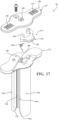
- the lock mechanism 176 includes a biasing element 180, for example, a torsion spring shown in Figure 17 .
- the lock actuator 178 may be a U-shaped component including an input surface 182 and a first lock surface 184.
- the lock actuator 178 is pivotally coupled to the hub 148, in particular the lower and upper housings 172, 174.
- the lower housing 172 includes a second lock surface 186.
- the first and second lock surfaces 184, 186 at least partially surround the aperture 158 of the lower housing 172.
- the biasing element 180 is operably coupled to the lower housing 172 and the lock actuator 178, and the biasing element 180 is configured to bias the lock actuator 178 to a closed state in which a shaft of the treatment device is effectively squeezed between the first and second lock surfaces 184, 186.
- the torsion spring biases the first lock surface 184 towards the second lock surface 186 to engage the shaft of the treatment device.
- the lock actuator 178 in particular the input surface 182, is configured to receive an input from a user to selectively permit movement of the treatment device relative to the access cannula 34 or the sheath device 36.
- the input to the input surface 182 pivots the lock actuator 178 against the bias of the biasing element 180 to move the lock mechanism from the closed state to an open state in which the distance between the first and second lock surfaces 184, 186 is increased.
- the increase in distance lessens or eliminates the squeezing on the treatment device, after which the treatment device may be selectively moved relative to the spacer lock 40.
- the input surface 182 may be actuated with one hand of the practitioner, and with the other hand the practitioner proximally retracts the treatment device. Once positioned as desired, the practitioner merely removed the input to the input surface 182, after which the biasing element 180 returns the lock mechanism 176 from the open state to the closed state in which movement of the treatment device is again prevented.
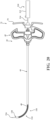
- FIG 18 shows another implementation of the spacer lock 40.
- the lock mechanism 176 includes the lock actuator 178 having the input surface 182, and the biasing element 180 operably coupled to the lock actuator 178 and the hub 148.
- the biasing element 180 may be a disc 183 having an opening and slots 188, 190 extending radially from the opening.
- the disc 183 may be coupled to the lower housing 172 such that the opening is coaxially aligned with the aperture 158.
- One of the slots 190 extends to the outer edge of the disc 183, and the other slots 188 result in thinned regions of the disc 183 that are configured to resiliently deflect when engaged by the lock actuator 178.
- a size of the opening is slightly smaller than a shaft of the treatment device such that the treatment device is prevented from moving relative to the spacer lock 40.
- the shaft of the treatment device is effectively "pinched" between tips of flanges defined by the slots 188, 190.
- the tips of flanges defined by the slots 188, 190 pinches the support member 163 of the cavity-forming device 160.
- the lock actuator 178 is slidably coupled to the hub 148.
- the lock actuator 178 may include rails 192 configured to engage slots 194 of the lower housing 172.
- a pin (not shown) slidably disposed with a cavity 196 permits the slidable movement of the lock actuator 178 relative to the lower housing 172, but prevents the lock actuator 178 from decoupling from the same.
- the lock actuator 178 may include a protrusion 198 shaped complementary to the slot 190. In the illustrated implementation, the slot 190 and the protrusion 198 are complementarily triangular when viewed in plan.
- the protrusion 198 is positioned within the slot 190, and the position of the shaft of the treatment device is maintained by engagement of the tips of flanges defined by the slots 188, 190.
- the tips of flanges defined by the slots 188, 190 pinches the support member 163 of the cavity-forming device 160.
- An input may be provided to the input surface 182 to move the lock mechanism 176 from the natural or closed state to the open state in which movement of the treatment device is permitted relative to the spacer lock 40.
- the lock actuator 178 is slidably moved relative to the hub 148, and the protrusion 198 forces the thinned regions of the disc 183 to resiliently deflect, for example, radially outward relative to the aperture 158.
- the resilient deflection of the thinned regions results in a diameter of the opening to increase in the open state by an extent sufficient to permit movement of the shaft of the treatment device relative to the spacer lock 40.
- the introducer device 32 and the sheath device 36 are deployed, and the introducer device 32 is removed from the sheath device 36.
- the cavity-forming device 160 is directed through the aperture 158 of the spacer lock 40 either before or after operably positioning the spacer lock 40 in engagement with the hub 42 of the access cannula 34.
- the distal end of the expandable member 164 may be in registration with the distal end 130 of the sheath 118.
- the lock mechanism 176 is in the closed state such that engagement of the tube 162 by the lock actuator 178 prevents movement of the cavity-forming device 160 relative to the spacer lock 40 (and thus also relative to the access cannula 34 and the sheath device 36).
- the expandable member 164 is unsheathed in a contralateral position within the vertebral body.
- moving the hub 72 of the sheath device 36 within the slots 150 of the spacer lock 40 results in corresponding movement of the distal end 130 of the sheath 118 to expose the expandable member 164 at the target site.
- the expandable member 164 is inflated to create a cavity within the vertebral body.
- the practitioner may wish to create a second cavity that is positioned ipsilaterally to the midline.
- the input is provided to the input surface 182 of the spacer lock 40 to move the lock mechanism 176 from the closed state to the open state.
- the lock mechanism 176 With the lock mechanism 176 in the open state, another input provided to the hub 166 proximally retracts the cavity-forming device 160 to the desired position.
- the input is released, and the lock mechanism 176 returns to the closed state.
- the expandable member 164 is unsheathed in the ipsilateral position within the vertebral body. During both instances where the expandable member 164 is unsheathed, the practitioner need not separately maintain the position of the cavity-forming device 160, thereby freeing him or her to focus on other aspects of the procedure.
- the practitioner may decide that the 30-millimeter expandable member is indicated. Given the relative size of the expandable member 164 relative to the vertebral body, it may be necessary to position the expandable member 164 on the midline of the vertebral body. As mentioned, however, the distal end 130 of the sheath 118 may be positioned contralaterally when deployed, and the distal end of the expandable member 164 may be in registration with the distal end 130 of the sheath 118. In order to position the expandable member 164 on the midline of the vertebral body, a slight proximal retraction of the cavity-forming device 160 may be indicated. The spacer lock 40 facilitates the proximal retraction of the cavity-forming device 160 without the practitioner needing to manually maintain its position, which is particularly beneficial during the subsequent unsheathing the expandable member 164 on the midline.
- the electrode probe 200 may include a hub 202, a shaft 204, and at least one emitter 206 at the end of the shaft 204.
- the electrode probe 200 is configured to be coupled to a source of electrical energy, and to provide the energy at the target site to ablate tissue.
- the tissue to be ablated may be a tumor, a nerve, or the like.
- the tissue may be the basivertebral nerve having a main branch that extends anteriorly to within the vertebral body generally along the midline of the same.
- the system 30 is well suited to ablate the basivertebral nerve.
- the introducer device 32 and the sheath device 36 are deployed, and the introducer device 32 is removed from the sheath device 36.
- the electrode probe 200 is directed through the aperture 158 of the spacer lock 40 either before or after operably positioning the spacer lock 40 in engagement with the hub 42 of the access cannula 34.
- the distal end of the emitter(s) 206 may be in registration with the distal end 130 of the sheath 118.
- This contralateral positioning of the emitter(s) 206 may be suboptimal for ablation of the basivertebral nerve.
- the input is provided to the input surface 182 of the spacer lock 40 to move the lock mechanism 176 from the closed state to the open state.
- the lock mechanism 176 With the lock mechanism 176 in the open state, another input provided to the electrode hub 202 to adjust the emitter(s) 206 to the desired position. The input is released, and the lock mechanism 176 returns to the closed state.
- the emitter(s) 206 is unsheathed in the desired position within the vertebral body.
- the emitter(s) 206 is powered to supply electrical energy to ablate the basivertebral nerve.
- the ablation of tissue is an optional step, and it may occur before or after creation of the cavity with the cavity-forming device 160. Further, it may be desirable to drill a bore within the vertebral body prior to or after positioning of the emitter(s) 206 and/or the expandable member 164 of the cavity-forming device 160. For example, the introducer device 32, the sheath device 36, the cavity-forming device 160, and/or any other component of the system 30 may encounter a bone tumor. In order to access within the tumor for optimal placement of the emitter(s) 206, a drill device 210 may be directed through the sheath 118.
- Figure 20 shows the drill device 210 including a handpiece 212, a shaft 214 extending from the handpiece 212, and a drill tip 216 coupled to the shaft 214.
- the shaft 214 includes a flexible region configured to navigate the curve assumed by the flexible region 124 of the sheath 118.
- the drill device 210 may be deployed beyond the distal end 130 of the sheath 118, and operated to resect the tumor.
- the drill device may be powered or manual.
- One exemplary drill device is the MicroFX Osteochondral Drilling (OCD) system manufactured by Stryker Corporation (Kalamazoo, Mich.).
- a manual drill device may include a knurled handle.
- the introducer device 32, the sheath device 36, the cavity-forming device 160, and/or any other component of the system 30 may encounter necrotic tissue.
- the drill device 210 may be used in the aforementioned manner. It is understood that the drill device 210 and corresponding workflow steps are optional.
- a biopsy needle may be used in the aforementioned manner to obtain a tissue sample for biopsy.
- the biopsy needle may include a flexible region configured to navigate the curve assumed by the flexible region 124 of the sheath 118.
- the biopsy needle may be deployed beyond the distal end 130 of the sheath 118, and operated to, for example, obtain a core sample of the tumor.
- the workflow may include delivering curable material (also known as bone cement) to within the vertebral body. This may be done with or without creating a cavity to receive the curable material.
- curable material also known as bone cement
- a curable material delivery system suitable for use with the system 30 of the present disclosure is described in commonly-owned International Patent Publication No. WO2019/200091, published October 17, 2019 , and United States Patent No. 6,547,432, issued April 15, 2003 , the entire contents of which are hereby incorporated by reference, and sold under the tradename PCD System by Stryker Corporation (Kalamazoo, Mich.).
- Still another suitable cement delivery system is disclosed in commonly owned United States Patent No. 7,658,537, issued February 9, 2010 , the entire contents of which are hereby incorporated by reference.
- the cement delivery system may include a tube 207 and a coupler 208 is adapted to be coupled to the fitting 120 of the sheath hub 72, as shown in Figure 20 .
- Curable material is delivered through the sheath 118 to the target site.
- the hub 72 of the sheath device 36 may be moved from the first position to the second position such that the sheath 118 may be proximally retracting while the curable material is being delivered in a retrograde manner.
- the sheath 118 is removed from the access cannula 34.
- the trocar may be reintroduced through the access cannula 34, and the access cannula 34 and trocar removed from the vertebral body.
- the overlying tissue may be sutured.
- FIGS. 22A-25C various configurations for deploying the treatment device within the vertebral body with a bipedicular approach are illustrated.
- certain aspects of the disclosure are directed to accessing the contralateral side of the vertebral body through a unipedicular approach.
- certain aspects of the present disclosure are directed to accessing the midline through a unipedicular approach for ablation of the basivertebral nerve.
- Utilizing the bipedicular approach in which there are two of the systems 30 of the present disclosure advantageously provides access to nearly all regions of the interior of the vertebral body.
- the illustrated figures show a schematic representation of the treatment device within the vertebral body, for example, after being deployed through the sheath 118 as previously explained.
- the treatment device is representative of the electrode probe 200 previously described, in which the emitters 206 of each of the electrode probes 200 are configured to be deployed in complementary configurations within the vertebral body to effectuate desired heating patterns once operated.
- One exemplary electrode probe that is sufficiently flexible for navigating the curved distal portion is described in United States Patent Publication No. 2013/0006232, published January 3, 2013 , the entire contents of which are hereby incorporated by reference.
- the electrode probe 200 may be bipolar or monopolar. It is contemplated that the electrode probe 200 may be irrigated such that a fluid is infused into the adjacent tissue prior to and/or during ablation. It is further contemplated that the electrode probe 200 may be cooled, for example, by circulating a fluid within pathways internal to the electrode probe 200.
- Figures 22A-22C illustrates a bipedicular approach in which each of the systems 30 are used to deploy the treatment devices ipsilaterally. Should this be known preoperatively, the angle of approach on the pedicles themselves may be adjusted owing to the curve anticipated to be assumed by the system 30 and ultimately the treatment device. Should this be desired after the access cannula 34 (and trocar) are deployed within the pedicle of the vertebral body, then adjustments may be made to the position the distal end 48 of the access cannula 34 at a specific point within the (bony) pedicle in anticipation of the curve of the introducer device 32, which, in certain implementations, is known and reproducible.
- Figure 22A shows each of the treatment devices positioned ipsilaterally and symmetrical about the midline of the vertebral body. Further, ends of the treatment devices are substantially in the same position in the anterior-posterior direction.
- Figures 22B and 22C show each of the treatment devices positioned substantially in the same position in the caudio-cranial direction.
- Figures 23A-23C illustrate a bipedicular approach in which the systems 30 are used to deploy one of the treatment devices ipsilaterally and the other one of the treatment devices contra laterally.
- the treatment device deployed ipsilaterally is on-axis, whereas the treatment device deployed contralaterally is curved in manners previously described.
- Figure 23A shows the end of the on-axis treatment device positioned anteriorly relative to the end of the off-axis treatment device.
- the reverse configuration is contemplated.
- Figure 23C shows the end of the on-axis treatment device positioned cranially relative to the end of the off-axis treatment device. The reverse configuration is contemplated.
- Figures 24A-24C illustrate a bipedicular approach in which each of the systems 30 are used to deploy the treatment devices contra laterally.
- the treatment devices are deployed off-axis and may be considered to overlap in the medio-lateral direction.
- Figure 24A shows the end of one the treatment devices positioned anteriorly relative to the end of the other treatment device. The reverse configuration is contemplated.
- Figures 24B and 24C show each of the treatment devices positioned substantially in the same position in the caudio-cranial direction.
- Figures 25A-25C illustrate a bipedicular approach in which each of the systems 30 are used to deploy the treatment devices contra laterally.
- the treatment devices are deployed off-axis and may be considered to overlap in the medio-lateral direction.
- Figure 25A shows the ends of the treatment devices being substantially in the same position in the anterior-posterior direction.
- Figures 25B and 25C show an end of one of the treatment devices positioned cranially relative to the end of the other treatment device. The reverse configuration is contemplated.
- Clause 1 - A method of augmenting a vertebral body with a system including (i) an access cannula, (ii) an introducer device including an actuator, a shaft including a proximal portion that is rigid and a distal portion that is articulable, and a pulling element coupled to the actuator, and (iii) a sheath including a flexible region, the method including: positioning a distal end of the access cannula within the vertebral body such that a lumen of the access cannula provides access to an interior region of the vertebral body along a longitudinal axis; directing the shaft of the introducer device and the sheath to within the access cannula such that the distal portion of the introducer device and the flexible region of the sheath remains within the access cannula, wherein the introducer device is in an unconstrained state in which the pulling element is at a first tension; thereafter, providing an input to the actuator to move the introducer device from the unconstrained state to a constrained state
- Clause 2 The method of clause 1, wherein the distal portion of the introducer device and the flexible region of the sheath and configured to plunge through cancellous bone within the vertebral body while assuming the curve.
- Clause 3 The method of clauses 1 or 2, wherein the step of directing the shaft and the sheath further includes positioning a distal end of the sheath in registration with the distal end of the access cannula.
- Clause 4 The method of clause 3, further including aligning indicia disposed on the sheath with a hub of the access cannula so as to position the distal end of the distal portion in registration with the distal end of the access cannula.
- Clause 5 The method of any one of clauses 1-4, further including: providing another input to the actuator to move the introducer device from the constrained state to the unconstrained state; and removing the introducer device from the sheath device, wherein the pulling element being at the first tension in the unconstrained state provides for removal of the introducer device from the sheath with the flexible region of the sheath remaining curved within the vertebral body.
- Clause 6 The method of clause 5, wherein the system further includes a spacer lock defining an aperture and including legs defining slots, and a treatment device, the method further including: engaging the legs of the spacer lock with a cannula hub of the access cannula such that the aperture is aligned with the lumen, and a sheath hub of the sheath is disposed within the slots; and directing the treatment device through the aperture to within the sheath, wherein the treatment device is flexible to bend along the curve of the flexible region of the sheath disposed within the vertebral body.
- Clause 7 The method of clause 6, further including: proximally moving the sheath hub within the slots of the spacer lock with corresponding movement of the sheath exposing the treatment device at a target location within the vertebral body; and performing augmentation of tissue of the vertebral body at the target location.
- Clause 8 The method of clauses 6 or 7, wherein the treatment device is one of a cavity-forming device configured to displace tissue, an electrode probe configured to ablate tissue, a drill for cutting tissue, a tissue capturing device for tissue biopsy.
- the treatment device is one of a cavity-forming device configured to displace tissue, an electrode probe configured to ablate tissue, a drill for cutting tissue, a tissue capturing device for tissue biopsy.
- Clause 9 The method of any one of clauses 6-8, wherein the spacer lock includes a lock actuator and a lock mechanism operably coupled to the lock actuator, the method further including: providing an input to the lock actuator to disengage the lock actuator from a shaft of the treatment device; and moving the shaft of the treatment device within the aperture of the spacer lock to selectively adjust a position of the treatment device relative to the access cannula.
- Clause 10 The method of clause 9, further including removing the input to the lock actuator to reengage the lock mechanism and the shaft of the treatment device, thereby preventing further movement of the treatment device relative to the access cannula.
- Clause 11 The method of any one of clauses 7-10, wherein the sheath includes a metal tube, and a polymeric sleeve coupled to the metal tube and extending between opposing ends of the flexible region, the method further including: removing the treatment device from the sheath, wherein a curved path remains in the vertebral body that is along the curve previously assumed by the introducer device; and advancing the flexible region of the sheath relative to the distal end of the access cannula, wherein a preformed bend of the polymeric sleeve facilitates the flexible region following the curved path.
- Clause 12 The method of clause 11, wherein the system includes a source of curable material, the method further including delivering the curable material through the sheath to within the vertebral body, wherein the polymeric sleeve prevents egress of the curable material through articulating features of the metal tube.
- Clause 14 - A method of augmenting a vertebral body with a system including (i) an access cannula, (ii) an introducer device including a shaft including a proximal portion that is rigid and a distal portion that is articulable, (iii) a sheath device including a sheath hub and a sheath having a flexible region positioned along the distal portion of the shaft, and (iv) a spacer lock including legs defining slots, the method including: positioning a distal end of the access cannula within the vertebral body to provide access to an interior region of the vertebral body along a longitudinal axis; directing the shaft of the introducer device and the sheath to within the access cannula; operating the introducer device to cause the distal portion of the shaft and the flexible region of the sheath to assume a curve within the interior region of the vertebral body; removing the shaft from the sheath, wherein the flexible region of the sheath remains along the curve; thereafter
- Clause 15 The method of clause 14, wherein the system includes a cavity-forming device including a hub, a tube extending from the hub, and an expandable member disposed at the end of the tube, the method further including: directing the expandable member and the tube through an aperture in the spacer lock such that the expandable member is in registration with a distal end of the sheath and the hub contacts the spacer lock; and moving the sheath hub within the slots towards the hub so as to expose the expandable member beyond the distal end of the sheath.
- Clause 16 The method of clauses 14 or 15, wherein the system includes an electrode probe including an electrode hub, an electrode shaft extending from the electrode hub, and a probe near an end of the electrode shaft, the method further including: directing the electrode shaft through an aperture in the spacer lock such that the probe is in registration with a distal end of the sheath and the electrode hub contacts the spacer lock; and moving the sheath hub within the slots towards the electrode hub so as to expose the probe beyond the distal end of the sheath.
- Clause 17 The method of any one of clauses 14-16, further including: removing the cavity-forming device from the sheath; and decoupling the spacer lock and the cavity-forming device from the access cannula, thereby exposing a Luer fitting on the sheath hub.
- Clause 18 The method of clause 15, wherein the spacer lock includes a lock actuator and a lock mechanism operably coupled to the lock actuator, the method further including: providing an input to the lock actuator to disengage the lock actuator from the tube of the cavity-forming device; and moving the tube within the aperture of the spacer lock to selectively adjust a position of the expandable member relative to the access cannula or the sheath.
- a method of augmenting a vertebral body with a system including (i) an access cannula, (ii) an introducer device including a shaft including a distal portion that is articulable with a pulling element, a handle defining a proximal opening, a control member coupled to the pulling element and defining a control surface, a resilient arm extending from the control member, and a lock head at an end of the resilient arm and defining a release surface, and (iii) a sheath having a flexible region positioned over the distal portion of the shaft, the method including: positioning a distal end of the access cannula within the vertebral body to provide access to an interior region of the vertebral body along a longitudinal axis; grasping the handle of the introducer device; directing the shaft of the introducer device and the sheath within the access cannula such that the distal portion of the introducer device and the distal portion of the sheath are beyond the distal end of the access cann
- Clause 20 - A method of augmenting a vertebral body with a system including (i) an access cannula, (ii) an introducer device including a shaft including a proximal portion that is rigid and a distal portion that is articulable, (iii) a sheath device including a sheath hub and a sheath having a flexible region positioned along the distal portion of the shaft, and (iv) a drill device including a flexible region, the method including: positioning a distal end of the access cannula within the vertebral body to provide access to an interior region of the vertebral body along a longitudinal axis; directing the shaft of the introducer device and the sheath beyond the access cannula; operating the introducer device to cause the distal portion of the shaft and the flexible region of the sheath to assume a curve within the interior region of the vertebral body; removing the introducer device from the sheath device with the flexible region of the sheath remaining in the curve; directing
- Clause 21 The method of clause 20, wherein the system includes an electrode probe including an electrode hub, an electrode shaft extending from the electrode hub, and a probe near the end of the electrode shaft, the method further including: directing the electrode shaft through the sheath; exposing the probe beyond the distal end of the sheath and within the bore; and operating the probe to ablate tissue within the vertebral body.
- Clause 22 The method of clause 20, wherein the system includes a cavity-forming device including a hub, a tube extending from the hub, and an expandable member disposed at the end of the tube, the method further including: directing the expandable member through the sheath; exposing the probe beyond the distal end of the sheath and within the bore; inflating the expandable member to provide a cavity within the vertebral body; and deflating and then removing the expandable member from the sheath.
- Clause 23 The method of clause 22, wherein the system includes a source of curable material, the method further including delivering the curable material through the sheath to within the cavity of the vertebral body.
- Clause 24 - A method of augmenting a vertebral body with a system including (i) an access cannula, (ii) an introducer device including a shaft including a proximal portion that is rigid and a distal portion that is articulable, (iii) a sheath device including a sheath hub and a sheath having a flexible region positioned along the distal portion of the shaft, and (iv) a biopsy device including a flexible region, the method including: positioning a distal end of the access cannula within the vertebral body to provide access to an interior region of the vertebral body along a longitudinal axis; directing the shaft of the introducer device and the sheath beyond the access cannula; operating the introducer device to cause the distal portion of the shaft and the flexible region of the sheath to assume a curve within the interior region of the vertebral body; removing the introducer device from the sheath device with the flexible region of the sheath remaining in the curve; directing
- Clause 25 - A method of augmenting a bone with a system including (i) an access cannula, (ii) an introducer device including a shaft including a proximal portion that is rigid and a distal portion that is articulable, (iii) a sheath device including a sheath hub and a sheath having a flexible region positioned along the distal portion of the shaft, and (iv) an electrode probe including an electrode hub, an electrode shaft extending from the electrode hub, and a probe near an end of the electrode shaft, the method further including: positioning a distal end of the access cannula within the bone to provide access to an interior region of the bone along a longitudinal axis; directing the shaft of the introducer device and the sheath beyond the access cannula; operating the introducer device to cause the distal portion of the shaft and the flexible region of the sheath to assume a curve within the interior region of the bone; removing the introducer device from the sheath device with the flexible region of the she
- a spacer lock for a system for augmenting a vertebral body including an access cannula and a treatment device comprising: a hub defining an aperture sized to receive a shaft of the treatment device, the hub comprising grip surfaces positioned opposite the aperture; legs extending from the hub and configured to be positioned in abutment with the access cannula, wherein the legs define at least one slot; a lock actuator configured to receive an input from a user; and a lock mechanism configured to releasably engage a shaft of the treatment device in response to the lock actuator receiving the input so as to selectively permit movement of the treatment device relative to the spacer lock, wherein the grip surfaces are sized to be engaged by a thumb of a hand to facilitate movement of the treatment device with a syringe-style input.
- Clause 30 The spacer lock of any one of claims 27-29, wherein the at least one slot is two slots configured to slidably receive a sheath hub of a sheath device.
- a system for augmenting a vertebral body including: an access cannula including a cannula hub, and a cannula shaft extending from the cannula hub with the cannula shaft including a distal end positionable within the vertebral body and defining a lumen along a longitudinal axis; an introducer device including: an actuator configured to receive an input from a user; a shaft including a proximal portion that is rigid, and a distal portion that is articulable; and a pulling element coupled to the actuator and configured to be tensioned to move the introducer device from an unconstrained state in which the distal portion is oriented along the longitudinal axis, and a constrained state in which the distal portion is configured to assume a curve away from the longitudinal axis, wherein the shaft is removably disposed within a sheath, the sheath including a metal tube having articulating features to define a flexible region configured to extend along the distal portion of the shaft,
- Clause 36 The system of clause 34, wherein the metal tube is disposed within the polymeric sleeve.
- Clause 37 The system of clause 36, wherein the polymeric sleeve extends over the proximal portion to a sheath hub of the sheath.
- Clause 38 The system of any one of clauses 34-37, wherein the polymeric sleeve includes a preformed bend.
- Clause 39 The system of any one of clauses 34-38, further including a helical cut pattern within the flexible region of the metal tube.
- a sheath device for a system for augmenting a vertebral body including: a sheath hub; and a sheath including a proximal portion extending from the sheath hub along a longitudinal axis and including metal, and a distal portion including polymeric material, wherein the proximal portion is coupled to the distal portion at an interface including a plurality of protrusions on each of the proximal portion and the distal portion configured to engage one another and provide a constant inner diameter and a constant outer diameter across the interface.
- Clause 41 The sheath device of clause 40, wherein the plurality of protrusions are disposed equiangularly about the longitudinal axis.
- each of the plurality of protrusions includes a thinned region widening into a bulbous or circular profile.
- each of the plurality of protrusions on the proximal portion includes a barb.
- each of the plurality of protrusions of the proximal portion includes a tine that is wavy in shape.
Landscapes
- Health & Medical Sciences (AREA)
- Life Sciences & Earth Sciences (AREA)
- Surgery (AREA)
- Orthopedic Medicine & Surgery (AREA)
- Public Health (AREA)
- Veterinary Medicine (AREA)
- Biomedical Technology (AREA)
- Heart & Thoracic Surgery (AREA)
- Medical Informatics (AREA)
- Molecular Biology (AREA)
- Animal Behavior & Ethology (AREA)
- General Health & Medical Sciences (AREA)
- Engineering & Computer Science (AREA)
- Nuclear Medicine, Radiotherapy & Molecular Imaging (AREA)
- Dentistry (AREA)
- Oral & Maxillofacial Surgery (AREA)
- Pathology (AREA)
- Hematology (AREA)
- Immunology (AREA)
- Rheumatology (AREA)
- Physics & Mathematics (AREA)
- Fluid Mechanics (AREA)
- Surgical Instruments (AREA)
- Prostheses (AREA)
Applications Claiming Priority (3)
| Application Number | Priority Date | Filing Date | Title |
|---|---|---|---|
| US202063081449P | 2020-09-22 | 2020-09-22 | |
| PCT/US2021/051516 WO2022066743A2 (en) | 2020-09-22 | 2021-09-22 | Systems and methods for augmentation of a vertebral body |
| EP21801684.8A EP4216836B1 (de) | 2020-09-22 | 2021-09-22 | Systeme zur verstärkung eines wirbelkörpers |
Related Parent Applications (1)
| Application Number | Title | Priority Date | Filing Date |
|---|---|---|---|
| EP21801684.8A Division EP4216836B1 (de) | 2020-09-22 | 2021-09-22 | Systeme zur verstärkung eines wirbelkörpers |
Publications (2)
| Publication Number | Publication Date |
|---|---|
| EP4497402A2 true EP4497402A2 (de) | 2025-01-29 |
| EP4497402A3 EP4497402A3 (de) | 2025-04-02 |
Family
ID=78483472
Family Applications (2)
| Application Number | Title | Priority Date | Filing Date |
|---|---|---|---|
| EP24218618.7A Pending EP4497402A3 (de) | 2020-09-22 | 2021-09-22 | Systeme zur verstärkung eines wirbelkörpers |
| EP21801684.8A Active EP4216836B1 (de) | 2020-09-22 | 2021-09-22 | Systeme zur verstärkung eines wirbelkörpers |
Family Applications After (1)
| Application Number | Title | Priority Date | Filing Date |
|---|---|---|---|
| EP21801684.8A Active EP4216836B1 (de) | 2020-09-22 | 2021-09-22 | Systeme zur verstärkung eines wirbelkörpers |
Country Status (4)
| Country | Link |
|---|---|
| US (1) | US20230338045A1 (de) |
| EP (2) | EP4497402A3 (de) |
| CA (1) | CA3193177A1 (de) |
| WO (1) | WO2022066743A2 (de) |
Families Citing this family (10)
| Publication number | Priority date | Publication date | Assignee | Title |
|---|---|---|---|---|
| WO2013101772A1 (en) | 2011-12-30 | 2013-07-04 | Relievant Medsystems, Inc. | Systems and methods for treating back pain |
| EP4501263A3 (de) | 2019-09-12 | 2025-03-19 | Relievant Medsystems, Inc. | Systeme und verfahren zur gewebemodulation |
| WO2022011115A1 (en) | 2020-07-10 | 2022-01-13 | Relievant Medsystems, Inc. | Vertebral denervation in conjunction with vertebral fusion |
| US12082876B1 (en) | 2020-09-28 | 2024-09-10 | Relievant Medsystems, Inc. | Introducer drill |
| JP2024505335A (ja) | 2020-12-22 | 2024-02-06 | リリーバント メドシステムズ、インコーポレイテッド | 脊椎神経調節の候補の予測 |
| US12433668B1 (en) | 2021-11-08 | 2025-10-07 | Relievant Medsystems, Inc. | Impedance stoppage mitigation during radiofrequency tissue ablation procedures |
| USD1104262S1 (en) * | 2022-03-23 | 2025-12-02 | Stryker Corporation | Surgical introducer |
| EP4626337A1 (de) * | 2022-11-30 | 2025-10-08 | Medtronic Europe Sàrl | Basivertebrales nervenzugangswerkzeug, system und verfahren |
| EP4654908A1 (de) * | 2023-01-26 | 2025-12-03 | Relievant Medsystems, Inc. | Integrierte hochfrequenzvorrichtung zur intraossalen nervenablation |
| WO2025227023A1 (en) * | 2024-04-25 | 2025-10-30 | Arthrex, Inc. | Punch obturator |
Citations (9)
| Publication number | Priority date | Publication date | Assignee | Title |
|---|---|---|---|---|
| US6547432B2 (en) | 2001-07-16 | 2003-04-15 | Stryker Instruments | Bone cement mixing and delivery device for injection and method thereof |
| US7658537B2 (en) | 2006-10-06 | 2010-02-09 | Stryker Corporation | Bone cement mixing and delivery system with automated bone cement transfer between mixer and delivery device |
| US20130006232A1 (en) | 2002-09-30 | 2013-01-03 | Relievant Medsystems, Inc. | Methods of therapeutically heating a vertebral body to treat back pain |
| US8894658B2 (en) | 2009-11-10 | 2014-11-25 | Carefusion 2200, Inc. | Apparatus and method for stylet-guided vertebral augmentation |
| US9579130B2 (en) | 2008-04-08 | 2017-02-28 | Vexim Sas | Apparatus for restoration of the spine and methods of use thereof |
| US9839443B2 (en) | 2012-06-20 | 2017-12-12 | Stryker Corporation | Systems and methods for off-axis tissue manipulation |
| US10441295B2 (en) | 2013-10-15 | 2019-10-15 | Stryker Corporation | Device for creating a void space in a living tissue, the device including a handle with a control knob that can be set regardless of the orientation of the handle |
| WO2019200091A1 (en) | 2018-04-11 | 2019-10-17 | Stryker Corporation | Curable material dispensing system and methods of operating and packaging the same |
| US20200383707A1 (en) | 2019-06-07 | 2020-12-10 | Stryker Corporation | Systems and Methods for Off-Axis Augmentation of a Vertebral Body |
Family Cites Families (10)
| Publication number | Priority date | Publication date | Assignee | Title |
|---|---|---|---|---|
| US7641657B2 (en) * | 2003-06-10 | 2010-01-05 | Trans1, Inc. | Method and apparatus for providing posterior or anterior trans-sacral access to spinal vertebrae |
| WO2007089739A2 (en) * | 2006-01-27 | 2007-08-09 | Stryker Corporation | Low pressure delivery system and method for delivering a solid and liquid mixture into a target site for medical treatment |
| US20090131867A1 (en) * | 2007-11-16 | 2009-05-21 | Liu Y King | Steerable vertebroplasty system with cavity creation element |
| US8246627B2 (en) * | 2008-08-07 | 2012-08-21 | Stryker Corporation | Cement delivery device for introducing cement into tissue, the device having a cavity creator |
| CN102958456B (zh) * | 2010-04-29 | 2015-12-16 | Dfine有限公司 | 用于治疗椎骨骨折的系统 |
| US20130072941A1 (en) * | 2011-09-16 | 2013-03-21 | Francisca Tan-Malecki | Cement Injector and Cement Injector Connectors, and Bone Cement Injector Assembly |
| EP2892458B1 (de) * | 2012-09-07 | 2019-08-14 | Zimmer Knee Creations, Inc. | Vorrichtung für injektionen von flüssigkeiten in knochen |
| US10588691B2 (en) * | 2012-09-12 | 2020-03-17 | Relievant Medsystems, Inc. | Radiofrequency ablation of tissue within a vertebral body |
| CN103690228B (zh) * | 2013-12-12 | 2015-11-25 | 宁波华科润生物科技有限公司 | 椎体扩张球囊系统 |
| JP7125412B2 (ja) * | 2017-02-22 | 2022-08-24 | ストライカー・コーポレイション | 骨セメント送達システム用分流器 |
-
2021
- 2021-09-22 EP EP24218618.7A patent/EP4497402A3/de active Pending
- 2021-09-22 US US18/027,814 patent/US20230338045A1/en active Pending
- 2021-09-22 EP EP21801684.8A patent/EP4216836B1/de active Active
- 2021-09-22 CA CA3193177A patent/CA3193177A1/en active Pending
- 2021-09-22 WO PCT/US2021/051516 patent/WO2022066743A2/en not_active Ceased
Patent Citations (9)
| Publication number | Priority date | Publication date | Assignee | Title |
|---|---|---|---|---|
| US6547432B2 (en) | 2001-07-16 | 2003-04-15 | Stryker Instruments | Bone cement mixing and delivery device for injection and method thereof |
| US20130006232A1 (en) | 2002-09-30 | 2013-01-03 | Relievant Medsystems, Inc. | Methods of therapeutically heating a vertebral body to treat back pain |
| US7658537B2 (en) | 2006-10-06 | 2010-02-09 | Stryker Corporation | Bone cement mixing and delivery system with automated bone cement transfer between mixer and delivery device |
| US9579130B2 (en) | 2008-04-08 | 2017-02-28 | Vexim Sas | Apparatus for restoration of the spine and methods of use thereof |
| US8894658B2 (en) | 2009-11-10 | 2014-11-25 | Carefusion 2200, Inc. | Apparatus and method for stylet-guided vertebral augmentation |
| US9839443B2 (en) | 2012-06-20 | 2017-12-12 | Stryker Corporation | Systems and methods for off-axis tissue manipulation |
| US10441295B2 (en) | 2013-10-15 | 2019-10-15 | Stryker Corporation | Device for creating a void space in a living tissue, the device including a handle with a control knob that can be set regardless of the orientation of the handle |
| WO2019200091A1 (en) | 2018-04-11 | 2019-10-17 | Stryker Corporation | Curable material dispensing system and methods of operating and packaging the same |
| US20200383707A1 (en) | 2019-06-07 | 2020-12-10 | Stryker Corporation | Systems and Methods for Off-Axis Augmentation of a Vertebral Body |
Also Published As
| Publication number | Publication date |
|---|---|
| WO2022066743A3 (en) | 2022-05-12 |
| EP4216836B1 (de) | 2025-01-01 |
| EP4216836A2 (de) | 2023-08-02 |
| US20230338045A1 (en) | 2023-10-26 |
| WO2022066743A2 (en) | 2022-03-31 |
| EP4497402A3 (de) | 2025-04-02 |
| CA3193177A1 (en) | 2022-03-31 |
Similar Documents
| Publication | Publication Date | Title |
|---|---|---|
| EP4216836B1 (de) | Systeme zur verstärkung eines wirbelkörpers | |
| US12279799B2 (en) | Systems and methods for off-axis treatment of a vertebral body | |
| US12465400B2 (en) | Systems for off-axis treatment of a vertebral body | |
| EP3747385B1 (de) | Systeme zur ausseraxialen verstärkung eines wirbelkörpers | |
| EP3684277B1 (de) | Patientenmontierter chirurgischer träger | |
| US10945744B2 (en) | Drill guide with adjustable stop | |
| EP3881780B1 (de) | Trepan für perkutane seitliche vertiefung | |
| US20100069790A1 (en) | Medical apparatus with cannula and releasable handle assembly for accessing remote anatomical sites | |
| US20070282372A1 (en) | Guide forceps device for use with vertebral treatment device, system and methods of use | |
| US10849649B2 (en) | Hip obturator and method for atraumatic hip access | |
| US10524816B2 (en) | Tunnel tool for soft tissue | |
| HK40061446B (en) | Trephine for percutaneous lateral recess resection. |
Legal Events
| Date | Code | Title | Description |
|---|---|---|---|
| PUAI | Public reference made under article 153(3) epc to a published international application that has entered the european phase |
Free format text: ORIGINAL CODE: 0009012 |
|
| STAA | Information on the status of an ep patent application or granted ep patent |
Free format text: STATUS: THE APPLICATION HAS BEEN PUBLISHED |
|
| AC | Divisional application: reference to earlier application |
Ref document number: 4216836 Country of ref document: EP Kind code of ref document: P |
|
| AK | Designated contracting states |
Kind code of ref document: A2 Designated state(s): AL AT BE BG CH CY CZ DE DK EE ES FI FR GB GR HR HU IE IS IT LI LT LU LV MC MK MT NL NO PL PT RO RS SE SI SK SM TR |
|
| REG | Reference to a national code |
Ref country code: DE Ref legal event code: R079 Free format text: PREVIOUS MAIN CLASS: A61B0017880000 Ipc: A61B0017000000 |
|
| PUAL | Search report despatched |
Free format text: ORIGINAL CODE: 0009013 |
|
| AK | Designated contracting states |
Kind code of ref document: A3 Designated state(s): AL AT BE BG CH CY CZ DE DK EE ES FI FR GB GR HR HU IE IS IT LI LT LU LV MC MK MT NL NO PL PT RO RS SE SI SK SM TR |
|
| RIC1 | Information provided on ipc code assigned before grant |
Ipc: A61B 17/88 20060101ALI20250221BHEP Ipc: A61B 17/34 20060101ALI20250221BHEP Ipc: A61B 17/16 20060101ALI20250221BHEP Ipc: A61B 17/00 20060101AFI20250221BHEP |
|
| STAA | Information on the status of an ep patent application or granted ep patent |
Free format text: STATUS: REQUEST FOR EXAMINATION WAS MADE |
|
| GRAP | Despatch of communication of intention to grant a patent |
Free format text: ORIGINAL CODE: EPIDOSNIGR1 |
|
| STAA | Information on the status of an ep patent application or granted ep patent |
Free format text: STATUS: GRANT OF PATENT IS INTENDED |
|
| 17P | Request for examination filed |
Effective date: 20250916 |
|
| INTG | Intention to grant announced |
Effective date: 20251017 |
|
| GRAS | Grant fee paid |
Free format text: ORIGINAL CODE: EPIDOSNIGR3 |
|
| GRAA | (expected) grant |
Free format text: ORIGINAL CODE: 0009210 |
|
| STAA | Information on the status of an ep patent application or granted ep patent |
Free format text: STATUS: THE PATENT HAS BEEN GRANTED |