EP4497392A1 - Erzeugung eines oder mehrerer bewegungsindikatoren - Google Patents
Erzeugung eines oder mehrerer bewegungsindikatoren Download PDFInfo
- Publication number
- EP4497392A1 EP4497392A1 EP23187239.1A EP23187239A EP4497392A1 EP 4497392 A1 EP4497392 A1 EP 4497392A1 EP 23187239 A EP23187239 A EP 23187239A EP 4497392 A1 EP4497392 A1 EP 4497392A1
- Authority
- EP
- European Patent Office
- Prior art keywords
- location
- interest
- region
- sequence
- ultrasound
- Prior art date
- Legal status (The legal status is an assumption and is not a legal conclusion. Google has not performed a legal analysis and makes no representation as to the accuracy of the status listed.)
- Withdrawn
Links
Images

Classifications
-
- A—HUMAN NECESSITIES
- A61—MEDICAL OR VETERINARY SCIENCE; HYGIENE
- A61B—DIAGNOSIS; SURGERY; IDENTIFICATION
- A61B8/00—Diagnosis using ultrasonic, sonic or infrasonic waves
- A61B8/46—Ultrasonic, sonic or infrasonic diagnostic devices with special arrangements for interfacing with the operator or the patient
- A61B8/467—Ultrasonic, sonic or infrasonic diagnostic devices with special arrangements for interfacing with the operator or the patient characterised by special input means
- A61B8/469—Ultrasonic, sonic or infrasonic diagnostic devices with special arrangements for interfacing with the operator or the patient characterised by special input means for selection of a region of interest
-
- A—HUMAN NECESSITIES
- A61—MEDICAL OR VETERINARY SCIENCE; HYGIENE
- A61B—DIAGNOSIS; SURGERY; IDENTIFICATION
- A61B8/00—Diagnosis using ultrasonic, sonic or infrasonic waves
- A61B8/46—Ultrasonic, sonic or infrasonic diagnostic devices with special arrangements for interfacing with the operator or the patient
- A61B8/461—Displaying means of special interest
-
- A—HUMAN NECESSITIES
- A61—MEDICAL OR VETERINARY SCIENCE; HYGIENE
- A61B—DIAGNOSIS; SURGERY; IDENTIFICATION
- A61B8/00—Diagnosis using ultrasonic, sonic or infrasonic waves
- A61B8/52—Devices using data or image processing specially adapted for diagnosis using ultrasonic, sonic or infrasonic waves
-
- A—HUMAN NECESSITIES
- A61—MEDICAL OR VETERINARY SCIENCE; HYGIENE
- A61B—DIAGNOSIS; SURGERY; IDENTIFICATION
- A61B8/00—Diagnosis using ultrasonic, sonic or infrasonic waves
- A61B8/08—Clinical applications
-
- A—HUMAN NECESSITIES
- A61—MEDICAL OR VETERINARY SCIENCE; HYGIENE
- A61B—DIAGNOSIS; SURGERY; IDENTIFICATION
- A61B8/00—Diagnosis using ultrasonic, sonic or infrasonic waves
- A61B8/08—Clinical applications
- A61B8/0866—Clinical applications involving foetal diagnosis; pre-natal or peri-natal diagnosis of the baby
-
- A—HUMAN NECESSITIES
- A61—MEDICAL OR VETERINARY SCIENCE; HYGIENE
- A61B—DIAGNOSIS; SURGERY; IDENTIFICATION
- A61B8/00—Diagnosis using ultrasonic, sonic or infrasonic waves
- A61B8/08—Clinical applications
- A61B8/0883—Clinical applications for diagnosis of the heart
-
- A—HUMAN NECESSITIES
- A61—MEDICAL OR VETERINARY SCIENCE; HYGIENE
- A61B—DIAGNOSIS; SURGERY; IDENTIFICATION
- A61B8/00—Diagnosis using ultrasonic, sonic or infrasonic waves
- A61B8/46—Ultrasonic, sonic or infrasonic diagnostic devices with special arrangements for interfacing with the operator or the patient
- A61B8/461—Displaying means of special interest
- A61B8/463—Displaying means of special interest characterised by displaying multiple images or images and diagnostic data on one display
-
- A—HUMAN NECESSITIES
- A61—MEDICAL OR VETERINARY SCIENCE; HYGIENE
- A61B—DIAGNOSIS; SURGERY; IDENTIFICATION
- A61B8/00—Diagnosis using ultrasonic, sonic or infrasonic waves
- A61B8/52—Devices using data or image processing specially adapted for diagnosis using ultrasonic, sonic or infrasonic waves
- A61B8/5215—Devices using data or image processing specially adapted for diagnosis using ultrasonic, sonic or infrasonic waves involving processing of medical diagnostic data
- A61B8/5223—Devices using data or image processing specially adapted for diagnosis using ultrasonic, sonic or infrasonic waves involving processing of medical diagnostic data for extracting a diagnostic or physiological parameter from medical diagnostic data
-
- G—PHYSICS
- G06—COMPUTING OR CALCULATING; COUNTING
- G06T—IMAGE DATA PROCESSING OR GENERATION, IN GENERAL
- G06T7/00—Image analysis
- G06T7/0002—Inspection of images, e.g. flaw detection
- G06T7/0012—Biomedical image inspection
Definitions
- the present invention relates to the field of ultrasound imaging, and in particular to tracking the movement of a region of interest during ultrasound imaging.
- Ultrasound imaging is a popular technique for generating medical image data of a region of interest (ROI) of a medical subject.
- ultrasound imaging is one of the most widely used techniques to monitor the growth of a fetus in a womb of a medical subject.
- CT computerized tomography
- MR magnetic resonance
- ultrasound imaging can be performed using a handheld device. This portability provides significant flexibility of use for ultrasound imaging devices compared to other medical imaging modalities.
- a handheld ultrasound transducer e.g., a handheld ultrasound transducer
- the quality of any resulting ultrasound images will depend heavily upon the manipulation of handheld device by the operator thereof.
- a slight deviation of the transducer can cause a major difference in the view plane of the images.
- This movement may be due to a movement of the ultrasound device, the subject being monitored or the region of interest within the subject being monitored.
- a computer-implemented method for outputting one or more indicators for a movement of a region of interest within a sequence of ultrasound images of a medical subject is provided.
- the computer-implemented method comprises: obtaining the sequence of ultrasound images of a medical subject; for each ultrasound image in the sequence, processing the ultrasound image to identify the location of a region of interest (ROI) within the ultrasound image, performing a ROI characterization procedure for each ultrasound image in the sequence, the ROI characterization procedure comprising: determining a distance and/or direction between a reference location and the identified location of the region of interest; and/or determining a relative position of the identified location of the region of interest with respect to the reference location; and outputting one or more indicators responsive to the determined distance, direction and/or relative position for each ultrasound image.
- ROI region of interest
- the present disclosure thereby provides a mechanism for providing indicators about a movement of a region of interest within a sequence of ultrasound images.
- information on the movement with respect to a reference location is output, e.g., for display and/or further processing.
- the reference location is a non-origin location of each ultrasound image, i.e., a location that is not positioned at the origin of a Euclidean or Cartesian co-ordinate system defining locations with each ultrasound image.
- the reference location is the same for all ultrasound images in the sequence.
- the ROI characterization procedure comprising determining at least a direction between a reference location and the identified location of the region of interest.
- the reference location is the average location of the region of interest across the sequence of ultrasound images. This helps provide readily interpretable information about a deviation of the region of interest from an average point, providing more useful information about a stability of the location of the region of interest across the sequence of ultrasound images.
- the reference location a centroid of the ultrasound image; and/or a location positioned at a predetermined offset from the centroid of the ultrasound image.
- the reference location By defining the reference location to lie at the centroid of the ultrasound image, deviation from this preferred location can be immediately and readily identified.
- Use of such reference locations also facilitates real time determination of distances, directions and/or relative locations of locations of the regions of interest with respect to the reference location.
- the reference location is the average location of the region of interest across the sequence of ultrasound images; and the computer-implemented method further comprises processing the identified location of the region of interest within each ultrasound image to determine the average location of the region of interest across the sequence of ultrasound images.
- the reference location is a modal average location of the region of interest across the sequence of ultrasound images. This provides an indication of the deviation or movement from a most common position of the region of interest, e.g., to draw closer attention to sudden spikes or shifts of the region of interest.
- the ROI characterization procedure may comprise determining a distance between the reference location and the identified location of the region of interest.
- the step of outputting one or more indicators comprises determining an average distance by processing the determined distance for each ultrasound image in the sequence and outputting a distance indicator responsive to the determined average distance.
- the step of determining a distance between the reference location and the identified location of the region of interest comprises using the Pythagorean theorem to determine the distance between the reference location and the identified location of the region of interest. This provides an efficient technique for determining the distance between the two locations.
- the ROI characterization procedure may comprise determining a direction between the reference location and the identified location of the region of interest.
- the step of outputting one or more indicators may comprise determining an average direction by processing the determined direction for each ultrasound image in the sequence and outputting a direction indicator responsive to the determined average direction.
- the average direction is preferably a mean average direction. This approach helps provide guidance to an operator of the ultrasound imaging system, or reviewer of the sequence of ultrasound images, as to the movement of the ROI, and therefore how the movement should be compensated or taken into account during, for example, further ultrasound imaging and/or analysis of the sequence of ultrasound images.
- the step of determining a direction between the reference location and the identified location of the region of interest comprises using a trigonometric process to determine the direction between the reference location and the identified location of the region of interest.
- the ROI characterization procedure may comprise determining a relative position of the identified location of the region of interest, with respect to the reference location, in a polar co-ordinate system.
- the ROI characterization process comprises determining the distance and the direction between the reference location and the identified location of the region of interest; and in the ROI characterization process, the step of determining a relative position of the identified location of the region of interest, with respect to the reference location, in a polar co-ordinate system comprises, processing the determined distance and direction to produce polar co-ordinates of the identified location within the polar co-ordinate system.
- the identified location of the region of interest and the reference location are defined using Cartesian co-ordinates in a Cartesian co-ordinate system; and in the ROI characterization process, the step of determining a relative position of the identified location of the region of interest, with respect to the reference location, in a polar co-ordinate system comprises, for each dimension of the Cartesian co-ordinate system: producing a quotient by dividing the value of the identified location by the value of the reference location; and multiplying the quotient by a highest possible value for the dimension of the Cartesian co-ordinate system with respect to the ultrasound image.
- a processing system for outputting one or more indicators for a movement of a region of interest within a sequence of ultrasound images of a medical subject, the processing system being configured to carry out the above method, i.e.: obtain the sequence of ultrasound images of a medical subject; for each ultrasound image in the sequence, process the ultrasound image to identify the location of a region of interest within the ultrasound image, perform an ROI characterization procedure for each ultrasound image in the sequence, the ROI characterization procedure comprising: determining a distance and/or direction between a reference location and the identified location of the region of interest; and/or determining a relative position of the identified location of the region of interest with respect to the reference location; and output one or more indicators responsive to the determined distance, direction and/or relative position for each ultrasound image.
- the reference location is one of: the average location of the region of interest across the sequence of ultrasound images; a centroid of the ultrasound image; and/or a location positioned at a predetermined offset from the centroid of the ultrasound image.
- a user interface system comprising the processing system and a user interface.
- the processing system is configured to control the user interface to provide a user-perceptible representation (e.g., a display) of the one or more indicators.
- a user-perceptible representation e.g., a display
- This approach advantageously provides information to an operator of the ultrasound system and/or an analyzer of the sequence of ultrasound images about the movement of the region of interest.
- an ultrasound imaging system comprising an ultrasound transducer configured to generate the sequence of ultrasound images of the medical subject and the processing system herein disclosed.
- the imaging system comprises the user interface system (of which the processing system forms a part).
- the invention provides a mechanism for generating one or more indicators about a movement of a region of interest through a sequence of ultrasound images.
- a reference location is defined with respect to the ultrasound images.
- For each ultrasound image a relative position, direction and/or distance of the region of interest from or with respect to the reference location is identified.
- One or more indicators are produced responsive to the determined position, direction and/or distance of the region of interest.
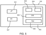
- Fig. 1 illustrates an (ultrasound) imaging system 10 in which proposed embodiments can be employed.
- the imaging system 10 comprises an ultrasound transducer system 190 (e.g., an ultrasound transducer), a processing system 100 and a (optional) user interface 110.
- the processing system is, by itself, an embodiment of the proposed approach.
- the ultrasound transducer system 190 is configured to perform an ultrasound imaging procedure on a medical subject 199 to produce a sequence 150 of ultrasound images. Approaches for performing an ultrasound imaging procedure to produce such a sequence of ultrasound images are well known in the art, and are not detailed for the sake of conciseness.
- Each ultrasound image is a multidimensional image (e.g., a 2D image or a 3D image) containing a representation of a portion of the medical subject as detected using ultrasound waves.
- a sequence of ultrasound images may comprise a temporal sequence, e.g., where each successive ultrasound image is captured or represents a later point/period in time to an earlier ultrasound image in the sequence.
- a temporal sequence e.g., where each successive ultrasound image is captured or represents a later point/period in time to an earlier ultrasound image in the sequence.
- the sequence may be a spatial sequence, e.g., where each successive ultrasound image represents a different location or imaged region.
- an ultrasound image contains only a representation of the imaged portion of the medical subject.
- an ultrasound image may be accompanied by additional information (e.g., scale information, medical subject and so on).
- the processing system 100 is configured to output one or more indicators for a movement of a region of interest within the sequence 150 of ultrasound images.
- the one or more indicators may be used, for instance, to control the user interface 110, e.g., to provide a visual representation of the one or more indicators.
- the processing system 100 is configured to obtain the sequence 150 of ultrasound images.
- the sequence 150 may be obtained directly from the ultrasound transducer system 190 or a database 196 that is itself configured to receive the sequence 150 from the ultrasound transducer system 190.
- Other approaches for retrieving or obtaining a sequence of ultrasound images will be apparent to the skilled person.
- Fig. 2 is a flowchart illustrating a computer-implemented method 200 for outputting the one or more indicators for a movement of a region of interest within the sequence of ultrasound images of the medical subject.
- the method 200 may, for instance, be performed by the processing system 100.
- the method 200 comprises a step 210 of obtaining the sequence of ultrasound images of a medical subject. As previously explained, this may be performed by obtaining the sequence from an ultrasound transducer system and/or a database.
- the method 200 also comprises a step 220 of, for each ultrasound image in the sequence, processing the ultrasound image to identify the location of a region of interest within the ultrasound image.
- step 220 comprises localizing the region of interest within each ultrasound image.
- the location of the region of interest may be defined using a set of co-ordinates, e.g., Euclidean or Cartesian co-ordinates.
- a single set of co-ordinates (each co-ordinate representing a position along a different dimension) may define the location of the region of interest in a Euclidean space.
- the region of interest is the same for each ultrasound image in the sequence, and may, for instance, comprise a particular anatomical structure (e.g., an organ), feature and/or landmark.
- anatomical structure e.g., an organ
- the precise nature of the region of interest may be application or use-case scenario dependent. For instance, if the sequence of ultrasound images contains a representation of a fetus, then the region of interest may be the fetus. If the sequence of ultrasound images contains a representation of a thorax, then the region of interest may be an anatomical landmark of the heart.
- regions of interest include a femur (e.g., of a fetus), a head (e.g., of a fetus), a growth such as a cancerous growth, an infection, the entrance or exit of a vein or artery, one or more landmarks of the heart, a (kidney) stone, a vertebra and so on.
- a femur e.g., of a fetus
- a head e.g., of a fetus
- a growth such as a cancerous growth, an infection, the entrance or exit of a vein or artery, one or more landmarks of the heart, a (kidney) stone, a vertebra and so on.
- the average location may, for instance, be a modal average location.
- a modal average location is the location that is most common amongst the locations of all the region(s) of interest across the sequence of ultrasound images.
- process 230 comprises the step 231 of determining a distance (i.e., a measure of distance) between the reference location and the identified location of the region of interest.
- pi represents a position along an x axis for the pixel of the reference location
- p 2 represents a position along a y axis for the pixel of the reference location
- q 1 represents a position along an x axis for the pixel of the identified location
- q 1 represents a position along a y axis for the pixel of the identified location.
- Equation (1) defines the distance as a measure of pixel distance. It is possible to convert this distance into a true or spatial distance (e.g., measured in cm, mm or inches) by multiplying the distance D pixel(p,q) by a known pixel spacing PS, which represents a true distance between the positions represented by the centroids of two neighboring pixels.
- the above described process effective defines a mechanism for determining a Euclidean distance between the identified location (of the ROI of the ultrasound image) and the reference location.
- any other suitable form of distance measure can be used instead, such as a Manhattan distance or a Minkowski distance.
- the distance D may be normalized, e.g., to a maximum possible distance for movement of the region of interest within the ultrasound image, which will be dependent upon the size and/or resolution of the ultrasound image.
- step 240 comprises determining an average distance by processing the determined distance for each ultrasound image in the sequence and outputting a distance indicator responsive to the determined average distance. Determining an average distance preferably comprises determining a mean distance.
- the distance indicator may be the determined average distance itself.
- Such embodiments are particularly advantageous when the reference location is the average location (e.g., the modal or mean location) of the region of interest across the sequence of ultrasound images. This is because the average distance will provide useful information on the deviance or movement of the region of interest with respect to a center, which significantly influences an accuracy or interpretability of the region of interest across the sequence of ultrasound images.
- the average distance will provide useful information on the deviance or movement of the region of interest with respect to a center, which significantly influences an accuracy or interpretability of the region of interest across the sequence of ultrasound images.
- step 240 comprises determining a weighted average distance by applying a weight (e.g., multiplying the distance by a weight value) to each determined distance for the ultrasound images before determining a mean average of the weighted distances.
- the distance indicator responsive to the determined weighted average distance, may then be output.
- Applying a weight may comprise increasing a weight value for distances of ultrasound images later in the sequence, e.g., captured at a later point in time. This places greater emphasis on the most recent locations of the region of interest, which will be of more relevance or interest to an operator or further processor.
- the weight value may decrease to zero for distances of ultrasound images earlier in the sequence, effectively creating a time-windowed average of the determined distances.
- an average distance, or weighted average distance finds particular use as a quality indicator or measure of the ultrasound imaging to produce the sequence of ultrasound imaging.
- the (weighted) average distance may be output for use by a further processing system or algorithm and/or displayed to an operator of the ultrasound transducer system (e.g., to facilitate a decision on whether to repeat the imaging).
- the ROI characterization procedure comprises determining a direction between the reference location and the identified location of the region of interest.
- the direction may be defined in terms of an angle from the reference location to the identified location.
- step 240 comprises determining an average direction by processing the determined direction for each ultrasound image in the sequence and outputting a direction indicator responsive to the determined average direction. Determining an average direction preferably comprises determining a mean direction.
- the direction indicator may be the determined average direction itself.
- Such embodiments are particularly advantageous when the reference location is the average location (e.g., the modal or mean location) of the region of interest across the sequence of ultrasound images. This is because the average direction will provide useful information on the deviance or movement of the region of interest with respect to a center, which significantly influences an accuracy or interpretability of the region of interest across the sequence of ultrasound images.
- the average direction will provide useful information on the deviance or movement of the region of interest with respect to a center, which significantly influences an accuracy or interpretability of the region of interest across the sequence of ultrasound images.
- step 240 comprises determining a weighted average direction. This may be performed by multiplying each determined distance by a respective weighting value, which is non-negative, to produce weighted determined distances. The sum of the weighted determined distances may then be divided by the sum of the non-negative integer weighting values to generate the weighted average direction. Step 240 may then output the direction indicator responsive to the determined weighted average direction.
- the value of the weighting value x i may increase for directions of ultrasound images later in the sequence, e.g., ultrasound images captured at a later point in time. This places greater emphasis on the most recent locations of the region of interest, which will be of more relevance or interest to an operator or further processor. In some instances, the weighting value may decrease to zero for distances of ultrasound images earlier in the sequence, effectively creating a time-windowed average of the determined distances.
- An average direction, or weighted average direction finds particular use as a quality indicator or measure of the ultrasound imaging to produce the sequence of ultrasound imaging.
- the (weighted) average direction may be output for use by a further processing system or algorithm and/or displayed to an operator of the ultrasound transducer system (e.g., to facilitate a decision on whether to repeat the imaging).
- the ROI characterization procedure comprises determining a relative position of the identified location of the region of interest, with respect to the reference location, in a polar co-ordinate system.
- Each identified relative position may define a respective indicator to be output or used to control an output.
- One approach for determining such a relative position is to determine, for each ultrasound image, a direction and distance of the identified location from the reference location using the techniques previously disclosed . This defines the relative position in the polar co-ordinate system.
- Another approach is to directly convert the location of the ROI (e.g., defined as co-ordinates in a Euclidean space) to a position (x n , y n ) in a polar co-ordinate system.
- the step of determining a relative position of the identified location of the region of interest, with respect to the reference location, in a polar co-ordinate system comprises, for each dimension of the Cartesian co-ordinate system: producing a quotient by dividing the value of the identified location by the value of the reference location; and multiplying the quotient by a highest possible value for the dimension of the Cartesian co-ordinate system with respect to the ultrasound image.
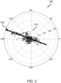
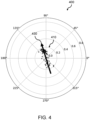
- step 240 comprises controlling a user interface to provide a display of the determined relative positions in the polar co-ordinate system. This provides a useful and readily interpretable map for an operator to understand an amount of movement and a trend or direction of movement. In particular, this display provides information on the direction of any movement of the region of interest.
- step 240 is configured to define a property of each displayed relative position responsive to a position of the corresponding ultrasound image in the sequence of ultrasound images. For instance, the display of relative positions associated with ultrasound images later in the sequence may be controlled to be more prominently displayed (e.g., greater intensity of display, more opaque, or larger) than the display of relative positions associated with ultrasound images earlier in the sequence. In this way, the display of old points will fade away as new points are made available.
- suitable properties for a display of a relative position include: opacity; color; intensity; size; shape; pattern and so on.
- step 240 comprises determining a line of best fit or a trend through the relative positions in the polar co-ordinate system.
- This line of best fit or trend provides useful information on an amount and/or general direction of movement of the region of interest, to help guide an operator of the ultrasound transducer system to compensate or correct for such movement in future imaging procedures. It will be appreciated that the line of best fit or trend will lie along or define an average direction of the region of interest from the reference point.
- the line of best fit may be determined using known or existing plotting techniques, e.g., using the approach put forward by Pearson, Karl. "LIII. On lines and planes of closest fit to systems of points in space.” The London, Edinburgh, and Dublin philosophical magazine and journal of science 2.11 (1901): 559-572 ; or Bland, J. A. "A line of best fit.” International Journal of Mathematical Education in Science and Technology 16.5 (1985): 589-592 .
Landscapes
- Health & Medical Sciences (AREA)
- Life Sciences & Earth Sciences (AREA)
- Engineering & Computer Science (AREA)
- Biomedical Technology (AREA)
- Medical Informatics (AREA)
- Pathology (AREA)
- Radiology & Medical Imaging (AREA)
- Biophysics (AREA)
- Physics & Mathematics (AREA)
- Heart & Thoracic Surgery (AREA)
- Nuclear Medicine, Radiotherapy & Molecular Imaging (AREA)
- Molecular Biology (AREA)
- Surgery (AREA)
- Animal Behavior & Ethology (AREA)
- General Health & Medical Sciences (AREA)
- Public Health (AREA)
- Veterinary Medicine (AREA)
- Computer Vision & Pattern Recognition (AREA)
- Ultra Sonic Daignosis Equipment (AREA)
Priority Applications (3)
| Application Number | Priority Date | Filing Date | Title |
|---|---|---|---|
| EP23187239.1A EP4497392A1 (de) | 2023-07-24 | 2023-07-24 | Erzeugung eines oder mehrerer bewegungsindikatoren |
| PCT/EP2024/070793 WO2025021778A1 (en) | 2023-07-24 | 2024-07-23 | Generating one or more indicators of movement |
| CN202480049005.5A CN121586545A (zh) | 2023-07-24 | 2024-07-23 | 生成一个或多个运动指示符 |
Applications Claiming Priority (1)
| Application Number | Priority Date | Filing Date | Title |
|---|---|---|---|
| EP23187239.1A EP4497392A1 (de) | 2023-07-24 | 2023-07-24 | Erzeugung eines oder mehrerer bewegungsindikatoren |
Publications (1)
| Publication Number | Publication Date |
|---|---|
| EP4497392A1 true EP4497392A1 (de) | 2025-01-29 |
Family
ID=87474358
Family Applications (1)
| Application Number | Title | Priority Date | Filing Date |
|---|---|---|---|
| EP23187239.1A Withdrawn EP4497392A1 (de) | 2023-07-24 | 2023-07-24 | Erzeugung eines oder mehrerer bewegungsindikatoren |
Country Status (3)
| Country | Link |
|---|---|
| EP (1) | EP4497392A1 (de) |
| CN (1) | CN121586545A (de) |
| WO (1) | WO2025021778A1 (de) |
Citations (4)
| Publication number | Priority date | Publication date | Assignee | Title |
|---|---|---|---|---|
| US5538004A (en) * | 1995-02-28 | 1996-07-23 | Hewlett-Packard Company | Method and apparatus for tissue-centered scan conversion in an ultrasound imaging system |
| US20150272543A1 (en) * | 2014-04-01 | 2015-10-01 | Samsung Medison Co., Ltd. | Ultrasound diagnostic apparatus and method of operating the same |
| US20200090327A1 (en) * | 2016-12-15 | 2020-03-19 | Koninklijke Philips N.V. | Prenatal ultrasound imaging |
| US20210145413A1 (en) * | 2018-04-17 | 2021-05-20 | Koninklijke Philips N.V. | Ultrasound processing unit and method, and imaging system |
-
2023
- 2023-07-24 EP EP23187239.1A patent/EP4497392A1/de not_active Withdrawn
-
2024
- 2024-07-23 WO PCT/EP2024/070793 patent/WO2025021778A1/en active Pending
- 2024-07-23 CN CN202480049005.5A patent/CN121586545A/zh active Pending
Patent Citations (4)
| Publication number | Priority date | Publication date | Assignee | Title |
|---|---|---|---|---|
| US5538004A (en) * | 1995-02-28 | 1996-07-23 | Hewlett-Packard Company | Method and apparatus for tissue-centered scan conversion in an ultrasound imaging system |
| US20150272543A1 (en) * | 2014-04-01 | 2015-10-01 | Samsung Medison Co., Ltd. | Ultrasound diagnostic apparatus and method of operating the same |
| US20200090327A1 (en) * | 2016-12-15 | 2020-03-19 | Koninklijke Philips N.V. | Prenatal ultrasound imaging |
| US20210145413A1 (en) * | 2018-04-17 | 2021-05-20 | Koninklijke Philips N.V. | Ultrasound processing unit and method, and imaging system |
Non-Patent Citations (10)
| Title |
|---|
| BLAND, J. A.: "A line of best fit", INTERNATIONAL JOURNAL OF MATHEMATICAL EDUCATION IN SCIENCE AND TECHNOLOGY, vol. 16, no. 5, 1985, pages 589 - 592 |
| FIORENTINO, MARIA CHIARA ET AL.: "A review on deep-learning algorithms for fetal ultrasound-image analysis", MEDICAL IMAGE ANALYSIS, 2022, pages 102629 |
| JENNE J ET AL: "Ultrasound motion tracking for radiation therapy", RADIOLOGE, DER, SPRINGER, DE, vol. 55, no. 11, 5 October 2015 (2015-10-05), pages 984 - 991, XP035741851, ISSN: 0033-832X, [retrieved on 20151005], DOI: 10.1007/S00117-015-0027-0 * |
| JIANGPEIYUAN ET AL.: "A Review of Yolo algorithm developments", PROCEDIA COMPUTER SCIENCE, vol. 199, 2022, pages 1066 - 1073, XP086949719, DOI: 10.1016/j.procs.2022.01.135 |
| LIU, SHENGFENG ET AL.: "Deep learning in medical ultrasound analysis: a review", ENGINEERING, vol. 5, no. 2, 2019, pages 261 - 275, XP055653134, DOI: 10.1016/j.eng.2018.11.020 |
| MEIBURGER, KRISTEN M.U. RAJENDRA ACHARYAFILIPPO MOLINARI: "Automated localization and segmentation techniques for B-mode ultrasound images: A review", COMPUTERS IN BIOLOGY AND MEDICINE, vol. 92, 2018, pages 210 - 235, XP085333691, DOI: 10.1016/j.compbiomed.2017.11.018 |
| NOBLE, J. ALISONDJARNAL BOUKERROUI: "Ultrasound image segmentation: a survey", IEEE TRANSACTIONS ON MEDICAL IMAGING, vol. 25, no. 8, 2006, pages 987 - 1010, XP008085509, DOI: 10.1109/TMI.2006.877092 |
| PEARSONKARL: "The London, Edinburgh, and Dublin philosophical magazine and journal of science", vol. 2, 1901, article "LIII. On lines and planes of closest fit to systems of points in space", pages: 559 - 572 |
| REDMONJOSEPH ET AL.: "You only look once: Unified, real-time object detection", PROCEEDINGS OF THE IEEE CONFERENCE ON COMPUTER VISION AND PATTERN RECOGNITION, 2016 |
| WANG, ZIYANG: "Deep learning in medical ultrasound image segmentation: A review", ARXIV:2002.07703, 2020 |
Also Published As
| Publication number | Publication date |
|---|---|
| WO2025021778A1 (en) | 2025-01-30 |
| CN121586545A (zh) | 2026-02-27 |
Similar Documents
| Publication | Publication Date | Title |
|---|---|---|
| US8311296B2 (en) | Voting in mammography processing | |
| US8712133B2 (en) | Cardiac chamber volume computation from contours and base plane in cardiac MR Cine images | |
| US20110262015A1 (en) | Image processing apparatus, image processing method, and storage medium | |
| WO2018026431A1 (en) | Computer-aided diagnosis system for medical images using deep convolutional neural networks | |
| US20120027277A1 (en) | Interactive iterative closest point algorithm for organ segmentation | |
| CN113706473B (zh) | 超声图像中病灶区域的长短轴确定方法和超声设备 | |
| US11657909B2 (en) | Medical image processing apparatus and medical image processing method | |
| CN108805876B (zh) | 使用生物力学模型的磁共振和超声图像的可形变配准的方法和系统 | |
| EP4358850B1 (de) | Erzeugung von m-modus-daten zur erfassung von fötaler herzaktivität | |
| CN111539926A (zh) | 一种图像检测方法及装置 | |
| EP4497392A1 (de) | Erzeugung eines oder mehrerer bewegungsindikatoren | |
| CN119263064B (zh) | 一种起重机吊钩位置感知和安全预警方法及系统 | |
| US10169874B2 (en) | Surface-based object identification | |
| CN120635120A (zh) | 一种目标边界的确定方法、三维掩码的生成方法以及电子设备 | |
| US20100202674A1 (en) | Voting in mammography processing | |
| EP4702934A1 (de) | Verarbeitung von ultraschall-bilddaten | |
| CN120279211B (zh) | 超声图像的三维重建方法、计算机设备及存储介质 | |
| JP6757242B2 (ja) | 線維状組織抽出装置、線維状組織抽出方法並びに線維状組織抽出プログラム | |
| JP7800774B2 (ja) | 3d画像の処理 | |
| EP4108178A1 (de) | Erzeugung von m-modus-daten zur erfassung von fötaler herzaktivität | |
| CN119600045A (zh) | 一种超声检查报告生成方法、设备及装置 | |
| CN116912197A (zh) | 一种评估参数的确定方法、装置、电子设备及存储介质 | |
| CN119540263A (zh) | 超声成像方法和装置、电子设备和存储介质 | |
| CN113836832A (zh) | 一种确定血管状态参数的方法和装置 | |
| CN120108661A (zh) | 一种基于三维影像的骨科耗材核定方法及系统 |
Legal Events
| Date | Code | Title | Description |
|---|---|---|---|
| PUAI | Public reference made under article 153(3) epc to a published international application that has entered the european phase |
Free format text: ORIGINAL CODE: 0009012 |
|
| STAA | Information on the status of an ep patent application or granted ep patent |
Free format text: STATUS: THE APPLICATION HAS BEEN PUBLISHED |
|
| AK | Designated contracting states |
Kind code of ref document: A1 Designated state(s): AL AT BE BG CH CY CZ DE DK EE ES FI FR GB GR HR HU IE IS IT LI LT LU LV MC ME MK MT NL NO PL PT RO RS SE SI SK SM TR |
|
| STAA | Information on the status of an ep patent application or granted ep patent |
Free format text: STATUS: THE APPLICATION IS DEEMED TO BE WITHDRAWN |
|
| 18D | Application deemed to be withdrawn |
Effective date: 20250730 |