EP4497333A2 - Vorrichtung zur herstellung von verstärkungsmaterial für zigarettenfilter und zigarettenfilter mit darin eingesetztem verstärkungsmaterial - Google Patents
Vorrichtung zur herstellung von verstärkungsmaterial für zigarettenfilter und zigarettenfilter mit darin eingesetztem verstärkungsmaterial Download PDFInfo
- Publication number
- EP4497333A2 EP4497333A2 EP24181502.6A EP24181502A EP4497333A2 EP 4497333 A2 EP4497333 A2 EP 4497333A2 EP 24181502 A EP24181502 A EP 24181502A EP 4497333 A2 EP4497333 A2 EP 4497333A2
- Authority
- EP
- European Patent Office
- Prior art keywords
- paper tube
- paper
- reinforcing material
- cylindrical
- filter
- Prior art date
- Legal status (The legal status is an assumption and is not a legal conclusion. Google has not performed a legal analysis and makes no representation as to the accuracy of the status listed.)
- Pending
Links
Images


Classifications
-
- A—HUMAN NECESSITIES
- A24—TOBACCO; CIGARS; CIGARETTES; SIMULATED SMOKING DEVICES; SMOKERS' REQUISITES
- A24D—CIGARS; CIGARETTES; TOBACCO SMOKE FILTERS; MOUTHPIECES FOR CIGARS OR CIGARETTES; MANUFACTURE OF TOBACCO SMOKE FILTERS OR MOUTHPIECES
- A24D3/00—Tobacco smoke filters, e.g. filter-tips, filtering inserts; Filters specially adapted for simulated smoking devices; Mouthpieces for cigars or cigarettes
- A24D3/02—Manufacture of tobacco smoke filters
- A24D3/0229—Filter rod forming processes
- A24D3/0233—Filter rod forming processes by means of a garniture
-
- A—HUMAN NECESSITIES
- A24—TOBACCO; CIGARS; CIGARETTES; SIMULATED SMOKING DEVICES; SMOKERS' REQUISITES
- A24D—CIGARS; CIGARETTES; TOBACCO SMOKE FILTERS; MOUTHPIECES FOR CIGARS OR CIGARETTES; MANUFACTURE OF TOBACCO SMOKE FILTERS OR MOUTHPIECES
- A24D3/00—Tobacco smoke filters, e.g. filter-tips, filtering inserts; Filters specially adapted for simulated smoking devices; Mouthpieces for cigars or cigarettes
- A24D3/02—Manufacture of tobacco smoke filters
- A24D3/025—Final operations, i.e. after the filter rod forming process
-
- A—HUMAN NECESSITIES
- A24—TOBACCO; CIGARS; CIGARETTES; SIMULATED SMOKING DEVICES; SMOKERS' REQUISITES
- A24D—CIGARS; CIGARETTES; TOBACCO SMOKE FILTERS; MOUTHPIECES FOR CIGARS OR CIGARETTES; MANUFACTURE OF TOBACCO SMOKE FILTERS OR MOUTHPIECES
- A24D3/00—Tobacco smoke filters, e.g. filter-tips, filtering inserts; Filters specially adapted for simulated smoking devices; Mouthpieces for cigars or cigarettes
- A24D3/02—Manufacture of tobacco smoke filters
- A24D3/0275—Manufacture of tobacco smoke filters for filters with special features
- A24D3/0287—Manufacture of tobacco smoke filters for filters with special features for composite filters
-
- A—HUMAN NECESSITIES
- A24—TOBACCO; CIGARS; CIGARETTES; SIMULATED SMOKING DEVICES; SMOKERS' REQUISITES
- A24D—CIGARS; CIGARETTES; TOBACCO SMOKE FILTERS; MOUTHPIECES FOR CIGARS OR CIGARETTES; MANUFACTURE OF TOBACCO SMOKE FILTERS OR MOUTHPIECES
- A24D3/00—Tobacco smoke filters, e.g. filter-tips, filtering inserts; Filters specially adapted for simulated smoking devices; Mouthpieces for cigars or cigarettes
- A24D3/04—Tobacco smoke filters characterised by their shape or structure
-
- B—PERFORMING OPERATIONS; TRANSPORTING
- B31—MAKING ARTICLES OF PAPER, CARDBOARD OR MATERIAL WORKED IN A MANNER ANALOGOUS TO PAPER; WORKING PAPER, CARDBOARD OR MATERIAL WORKED IN A MANNER ANALOGOUS TO PAPER
- B31C—MAKING WOUND ARTICLES, e.g. WOUND TUBES, OF PAPER, CARDBOARD OR MATERIAL WORKED IN A MANNER ANALOGOUS TO PAPER
- B31C11/00—Machinery for winding combined with other machinery
- B31C11/02—Machinery for winding combined with other machinery for additionally shaping the articles
-
- B—PERFORMING OPERATIONS; TRANSPORTING
- B31—MAKING ARTICLES OF PAPER, CARDBOARD OR MATERIAL WORKED IN A MANNER ANALOGOUS TO PAPER; WORKING PAPER, CARDBOARD OR MATERIAL WORKED IN A MANNER ANALOGOUS TO PAPER
- B31C—MAKING WOUND ARTICLES, e.g. WOUND TUBES, OF PAPER, CARDBOARD OR MATERIAL WORKED IN A MANNER ANALOGOUS TO PAPER
- B31C5/00—Making tubes or pipes without using mandrels
-
- A—HUMAN NECESSITIES
- A24—TOBACCO; CIGARS; CIGARETTES; SIMULATED SMOKING DEVICES; SMOKERS' REQUISITES
- A24C—MACHINES FOR MAKING CIGARS OR CIGARETTES
- A24C5/00—Making cigarettes; Making tipping materials for, or attaching filters or mouthpieces to, cigars or cigarettes
- A24C5/01—Making cigarettes for simulated smoking devices
Definitions
- the present invention relates to an apparatus for manufacturing a paper reinforcing material for cigarette filters and a cigarette filter into which the paper reinforcing material is inserted, and more particularly, to an apparatus for manufacturing a paper reinforcing material for cigarette filters that improves durability of cigarette filters and a cigarette filter into which the paper reinforcing material is inserted.
- cigarettes are formed by wrapping tobacco leaves and other tobacco materials with cigarette paper and smoked to inhale cigarette smoke generated by burning the cigarette paper and the tobacco leaves.
- Filters are provided at inhaling parts of cigarettes to filter harmful components of the smoke and enhance the flavor of the smoke.
- cellulose acetate-based filters are microplastics manufactured by a reaction between an acetic acid solution and cellulose extracted from plants such as woods and cottonseeds.
- the cellulose acetate filters require a decomposition period of at least three years or more depending on environmental conditions.
- the discarded filters themselves or toxic substances adsorbed in the filters make decomposition by microorganisms difficult and cause various environmental problems.
- the paper filters are eco-friendly because they are typically made of plant-based natural fibers that are easily decomposed in nature and biodegradable and have a relatively smaller influence on the environment than the cellulose acetate fibers. Also, the paper filters are made of relatively cheap materials and are suitable for mass production, and thus production costs in manufacturing cigarettes may be reduced.
- the paper filters have a smaller number of fibers than the conventional filters and thus have a weak binding force. That is, since the paper filters have a lower density than the conventional filters, and it is difficult for cigarette paper to be perfectly adhered to tobacco leaves wrapped therewith, harmful substances are not effectively removed from cigarette smoke, and filter efficacy of the paper filters may be reduced as compared to the cellulose acetate filters.
- the paper filters are sensitive to heat and liquids and are easily deformed due to saliva, moisture, and the like generated while the smoker inhales cigarette smoke, the paper filters have a relatively low absorptive ability. That is, since liquids generated during smoking accumulate moisture therein, and the paper material absorbs the liquids, the inside of the paper filters is blocked, and an inhalation pressure increases.
- the paper filters are deformed or damaged due to the pressure of the smoker's mouth or teeth applied thereto when the paper filters are held in the smoker's mouth, the characteristics of paper make it impossible to restore the paper filters to their initial shapes, and the performance of filtering harmful substances is also degraded.
- the paper filters have lower durability than the conventional filters.
- the present invention is directed to providing an apparatus for manufacturing a paper reinforcing material for cigarette filters that improves durability of cigarette filters and a cigarette filter into which the paper reinforcing material is inserted.
- the present invention provides an apparatus for manufacturing a paper reinforcing material for cigarette filters, the apparatus including: a paper tube forming part configured to overlap wrapping paper in multiple layers and form a cylindrical paper tube that is hollow; a jig frame including a guider part provided for the cylindrical paper tube to be inserted thereinto in a longitudinal direction and a base support part provided to surround the guider part and having a plurality of through-holes formed at predetermined intervals in outer peripheral surfaces in a circumferential direction thereof; a plurality of pressure forming parts each disposed to pass through one of the through-holes in a radial direction and disposed to be spaced apart in the circumferential direction to press and compress an outer circumferential part of the cylindrical paper tube and form the cylindrical paper tube into a reinforcing material having a plurality of support wing parts formed thereon; and a preform jig provided at an inlet side of the jig frame and configured to provide a pressing force to form guideline grooves in the outer circumferential part
- the present invention also provides a cigarette filter into which a paper reinforcing material is inserted, the cigarette filter including: a filter rod part made of a paper material in which a paper tow that is made of a paper material and extends in a longitudinal direction is formed to be branched into a plurality of branch parts in a width direction and compressed in a cylindrical shape and has an outer circumferential surface wrapped with wrapping paper; a reinforcing filter part made of a paper material that is provided on at least any one of a front side and a rear side of the filter rod part and has a hollow type reinforcing material, which has a plurality of support wing parts formed thereon at predetermined angle intervals in a circumferential direction by pressing a cylindrical paper tube, wrapped with a paper tube to circumscribe the paper tube; and an outer paper tube configured to wrap around the filter rod part and the reinforcing filter part.
- the present invention provides the following advantageous effects.
- a cylindrical paper tube continuously supplied in a longitudinal direction has linear guideline grooves formed therein by a preform jig, and thus subsequent pressure forming is stably guided, the cylindrical paper tube can be prevented from being twisted and having a front end thereof broken due to clearances between pressure forming parts, and productivity can be significantly improved.
- the pressure forming parts are formed in multiple stages in a longitudinal direction of a jig frame and adjust an elastic spring to be inserted deeper into a forming hole toward the rear to selectively provide a pressing force to the cylindrical paper tube, a reinforcing material can be precisely formed, and the degree of precision of dimensions can be improved.
- a paper material is used for a reinforcing filter part having the reinforcing material inserted thereinto to maintain an eco-friendly characteristic, and support wing parts of the reinforcing material that are formed by overlapping wrapping paper in multiple layers support a paper tube wrapped around an outer circumferential surface thereof, the shape of the reinforcing filter part can be maintained, and deformation of the cigarette filter can be prevented.
- the apparatus for manufacturing a paper reinforcing material for cigarette filters is a manufacturing apparatus for inserting a reinforcing material into a paper cigarette filter and manufacturing a cigarette filter and may be understood as partially including an apparatus for manufacturing the cigarette filter excluding the reinforcing material.
- the apparatus for manufacturing a paper reinforcing material for cigarette filters is the same apparatus as a reinforcing material manufacturing apparatus and will be described and illustrated using the same reference numerals.
- FIG. 1 is a side view illustrating an apparatus for manufacturing a paper reinforcing material for cigarette filters according to one embodiment of the present invention
- FIG. 2 is a perspective view illustrating the apparatus for manufacturing a paper reinforcing material for cigarette filters according to one embodiment of the present invention
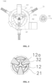
- FIG. 3 is a see-through front view illustrating the apparatus for manufacturing a paper reinforcing material for cigarette filters according to one embodiment of the present invention
- FIG. 4 is a cross-sectional view illustrating pressing by a forming roller in the apparatus for manufacturing a paper reinforcing material for cigarette filters according to one embodiment of the present invention.
- an apparatus 100 for manufacturing a paper reinforcing material for cigarette filters may include a paper tube forming part 10, a jig frame 20, pressure forming parts 30, and a preform jig 40.
- the paper tube forming part 10 may be provided at the last step after a series of processes for manufacturing a typical paper cigarette filter.
- the series of processes may include withdrawing and transferring a paper tow made of a paper material from a supply part 10a at a predetermined withdrawal speed and cutting the paper tow into predetermined widths by a cutting part 10b.
- branch parts obtained by cutting the paper tow into predetermined widths by the cutting part 10b may be overlapped in multiple layers to form a cylindrical paper tube that is hollow.
- the manufactured cylindrical paper tube consisting of multiple layers may be inserted into the jig frame 20 of the reinforcing material manufacturing apparatus 100 which will be described below, and the jig frame 20 may be formed to be provided at one side adjacent to the paper tube forming part 10.
- the jig frame 20 may include a guider part 21, fixing parts 22, and a base support part 23.
- a reinforcing material 12 made of a paper material that is provided in a paper cigarette filter may be formed in the jig frame 20.
- the guider part 21 provided so that the cylindrical paper tube is inserted thereinto in a longitudinal direction may be formed in the jig frame 20, and both ends of the guider part 21 may be restrained by the fixing parts 22.
- the guider part 21 may have a plurality of forming holes 21a formed at predetermined intervals in an outer circumferential surface in a circumferential direction and may be formed to extend in the longitudinal direction to guide the transfer of the cylindrical paper tube. Also, the forming holes 21a may be aligned to face through-holes 23a through which the pressure forming parts 30 pass.
- the guider part 21 may be fixed to a central portion inside the jig frame 20 by the fixing parts 22.
- the fixing parts 22 may be provided at both ends of the jig frame 20 and may be provided to be connected to the base support part 23 to restrain both ends of the jig frame 20 using fixing members corresponding to an outer diameter of the guider part 21 and be fixed to the central portion of the jig frame 20.
- the cylindrical paper tube may be inserted (i) into one side of the guider part 21 that is connected to the paper tube forming part 10.
- the cylindrical paper tube may be transferred to the guider part 21 by a separate transfer roller (not illustrated) present between the paper tube forming part 10 and the jig frame 20.
- the base support part 23 may be formed so that both ends are clamped to the fixing parts 22 and may be provided to wrap around an outer periphery of the guider part 21. In this case, a free space that allows the pressure forming parts 30 to come in contact with the guider part 21 and perform pressing may be formed in the base support part 23.
- the base support part 23 may be provided to be hollow, and outer peripheral surfaces of the base support part 23 in which the through-holes 23a are formed may be provided to be flat to allow the pressure forming parts 30 to be disposed.
- a surface of the base support part 23 on which the pressure forming parts 30 are not disposed may be formed to be open, and a transparent shield may be attached to the open surface to allow the inside of the jig frame 20 to be checked.
- the pressure forming parts 30 may each include a rod part 31 and a forming roller 32.
- the rod part 31 may be disposed to pass through one of the through-holes 23a and may be provided to extend in a radial direction to be inserted into the jig frame 20.
- a cylindrical case in which one end of the rod part 31 is accommodated may be provided on an outer surface of the base support part 23.
- a case step may be formed for the cylindrical case to be fixed to the base support part 23.
- an elastic spring 31a may be interposed at a rear end of the rod part 31 for the pressure forming part 30 to be selectively fixed at a pressing position in the radial direction.
- a tip of the rear end of the rod part 31 may be formed as a restraining part having a greater diameter than the rod part 31 for the elastic spring 31a to be provided between the cylindrical case and the restraining part.
- the elastic spring 31a may rotate, and the forming roller 32 may be inserted into the forming hole 21a and fixed at the pressing position.
- the pressing position may be understood as a depth at which the forming roller 32 is inserted into the cylindrical paper tube.
- the pressing position may be changed according to the number of rotations of the elastic spring 31a.
- the elastic spring 31a may be unlocked, and the forming roller 32 may move rearward in the forming hole 21a.
- the forming roller 32 may be rotatably connected to an end of the rod part 31 and may be provided in the base support part 23.
- the forming roller 32 may have a cross-section that gradually narrows outward.
- a fastening member that is connected to the forming roller 32 and allows the forming roller 32 to rotate may be fastened to the tip of the rod part 31.
- the fastening member may be connected to a center of the forming roller 32 for the forming roller 32 to rotate. That is, the cylindrical paper tube in the guider part 21 may be pressed and formed along the outer circumferential surface of the forming roller 32.
- the plurality of pressure forming parts 30 may be provided at predetermined intervals in the longitudinal direction of the jig frame 20 and may press the cylindrical paper tube.
- the pressure forming parts 30 are formed in multiple stages in the longitudinal direction of the jig frame 20 and are inserted deeper into the forming holes 21a toward the rear.
- the elastic spring 31a is adjusted to selectively provide a pressing force to the cylindrical paper tube in the longitudinal direction, the reinforcing material 12 can be precisely formed, and the degree of precision of dimensions can be improved.
- a presser configured to selectively press the pressure forming part 30 may be connected to the rear end of the rod part 31.
- a compressive force may be provided to the pressure forming part 30 by the presser utilizing pneumatic pressure, hydraulic pressure, and the like.
- the presser may be automated by an electric device to control the pressure forming part 30.
- the cylindrical paper tube may be formed into the reinforcing material 12 by the pressure forming parts 30.
- the reinforcing material 12 may have a plurality of support wing parts 12a formed thereon by pressing and compressing the outer circumferential part of the cylindrical paper tube.
- the preform jig 40 may include a preform main body part 41 and a preform protrusion 42.
- the preform jig 40 may be provided at an earlier step than the pressure forming parts 30.
- the preform jig 40 may be provided at one side of the jig frame 20, and the cylindrical paper tube may be preformed by the preform protrusion 42 and transferred. That is, the preform main body part 41 may be connected to an inlet side of the base support part 23 and have an insertion hole 41a through which the cylindrical paper tube passes formed therein.
- upper and lower portions of the preform main body part 41 may be coupled to the fixing parts 22 and fixed.
- the guider part 21 may be formed to be inserted into the insertion hole 41a.
- a plurality of preform protrusions 42 may be disposed on the preform main body part 41 corresponding to intervals at which the through-holes 23a are arranged in the circumferential direction.
- the preform protrusions 42 may come in frictional contact with and press the outer circumferential part of the cylindrical paper tube and form guideline grooves therein.
- the guideline grooves may be understood as lines formed by the preform protrusions 42 before the cylindrical paper tube is formed into the reinforcing material 12.
- the preform protrusions 42 may each have a spring provided at a rear end and a front end inserted into the guideline groove and may be formed to protrude to press the cylindrical paper tube.
- the preform protrusions 42 inserted into the forming holes 21a may be fixed by rotation of the springs.
- the presser connected to the rear end at which the spring is wound may be automated.
- the preform protrusions 42 may assist the pressure forming parts 30 in forming of the reinforcing material 12 made of a paper material, and the cylindrical paper tube pressed by the preform protrusions 42 may be preformed to form a preform paper tube 11a.
- the preform paper tube 11a may be transferred to the jig frame 20 by the guider part 21.
- the preform protrusions 42 may come in frictional contact with and press the outer circumferential part of the cylindrical paper tube along center lines between the support wing parts 12a to form the preform paper tube 11a having the guideline grooves formed therein.
- the forming roller 32 may be formed to have a narrower width than the preform protrusion 42 and may protrude to be closer to the center of the preform paper tube 11a than the preform protrusion 42 to apply pressure to the cylindrical paper tube along the guideline grooves of the preform paper tube 11a.
- the cylindrical paper tube continuously supplied in the longitudinal direction has the linear guideline grooves formed therein by the preform jig 40, subsequent pressure forming is stably guided. Therefore, the cylindrical paper tube can be prevented from being twisted and having a front end thereof broken due to clearances between pressure forming parts 30, and productivity can be significantly improved.
- the preform paper tube 11a formed by preforming of the cylindrical paper tube that is formed by overlapping wrapping paper in multiple layers is compressed and formed again by the pressure forming parts 30, and the strength of the reinforcing material 12 increases due to the wrapping paper overlapped in multiple layers being pressed and compressed, the durability of a cigarette filter 200 can be improved.
- a conveying device 22a may be provided at an outlet through which the reinforcing material 12 is discharged for the reinforcing material 12 to be transferred in a transfer direction of the base support part 23.
- the conveying device 22a may be fastened to the fixing part 22 at the opposite side of the fixing part 22 to which the preform jig 40 is attached.
- the conveying device 22a may be fastened to a lower end surface of a plate material coupled to the fixing part 22 to be perpendicular thereto and may be disposed at both sides with respect to the reinforcing material 12.
- the conveying device 22a may be provided in the shape of a roller having a groove formed therein and may rotate in conjunction with the grooves formed in the reinforcing material 12 and transfer the reinforcing material 12 forward.
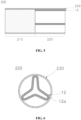
- the cigarette filter 200 into which the paper reinforcing material manufactured using the reinforcing material manufacturing apparatus 100 is inserted may be formed by coupling between a filter rod part 210 and a reinforcing filter part 220 which are made of a paper material.
- the filter rod part 210 and the reinforcing filter part 220 may be integrally formed by being wrapped together with an outer paper tube 230.
- the hollow type reinforcing material 12 which has the plurality of support wing parts 12a formed thereon at predetermined angle intervals in the circumferential direction by pressing and compressing the cylindrical paper tube formed by overlapping the wrapping paper in multiple layers, may be provided in the reinforcing filter part 220.
- the support wing parts 12a are formed at a plurality of sites at predetermined angle intervals in the circumferential direction and each have a cross-section that gradually narrows outward.
- the reinforcing filter part 220 may have an outer circumferential surface provided to be wrapped with wrapping paper to wrap around an outer surface of the reinforcing material 12.
- the reinforcing material 12 may be wrapped with wrapping paper (not illustrated) to circumscribe the wrapping paper (not illustrated).
- the filter rod part 210 may be manufactured in a cylindrical shape similar to the cylindrical paper tube. Specifically, the filter rod part 210 may be provided so that a paper tow that is made of a paper material and extends in the longitudinal direction is formed to be branched into a plurality of branch parts in a width direction and compressed in a cylindrical shape and has an outer circumferential surface wrapped with wrapping paper (not illustrated).
- the wrapping paper (not illustrated) wrapped around the filter rod part 210 and the wrapping paper (not illustrated) wrapped around the reinforcing filter part 220 may be understood as the same paper materials that are formed by the same manufacturing process.
- the paper tube (not illustrated) may be understood as being provided to be included in each of the filter rod part 210 and the reinforcing filter part 220.
- the reinforcing filter part 220 may be provided on at least any one of a front side and a rear side of the filter rod part 210 made of paper, and the filter rod part 210 may have a flavor enhancing capsule added thereto.
- the reinforcing filter part 220 having the reinforcing material 12 inserted thereinto to maintain an eco-friendly characteristic, and the support wing parts 12a of the reinforcing material 12 that are formed by overlapping wrapping paper in multiple layers support a paper tube wrapped around an outer circumferential surface thereof, the shape of the reinforcing filter part 220 can be maintained, and the deformation of the cigarette filter 200 can be prevented.
- FIG. 7 is a schematic diagram illustrating a manufacturing method using the apparatus for manufacturing a paper reinforcing material for cigarette filters according to one embodiment of the present invention.
- the cylindrical paper tube may be typically manufactured by a method of manufacturing a circular paper tube. That is, the cylindrical paper tube may be understood as being manufactured according to a series of processes before reaching the paper tube forming part 10 and being formed into the circular paper tube by the paper tube forming part 10 overlapping wrapping paper in multiple layers.
- the supply part 10a is provided to supply paper tow made of a paper material and withdraw and transfer the paper tow at a predetermined withdrawal speed.
- the cutting part 10b may be disposed at one side of the supply part 10a and may include a plurality of cutting blades configured to cut the paper tow so that the paper tow is branched into the plurality of branch parts at equal intervals in the width direction.
- each of the cutting blades may be disposed in a transfer direction of the paper tow. Accordingly, the paper tow supplied to the cutting part 10b may be continuously branched into the plurality of branch parts in the longitudinal direction of the paper tow.
- the paper tube forming part 10 may be disposed at one side of the cutting part 10b and may form the cylindrical paper tube by overlapping the branch parts in multiple layers, and the cylindrical paper tube may be transferred to the jig frame 20.
- the jig frame 20 may be provided to be connected to a second paper tube forming part 10c to allow the formed reinforcing material 12 to be immediately transferred to a subsequent process for an outer circumferential surface of the reinforcing material 12 to be wrapped with wrapping paper to form the reinforcing filter part 220.
- the second paper tube forming part 10c may be provided to wrap the outer circumferential surface of the reinforcing material 12 with the wrapping paper and manufacture the reinforcing filter part 220.
- the reinforcing material 12 is transferred to the second paper tube forming part 10c, which forms a circular paper tube to wrap around the outer circumferential surface of the reinforcing material 12, by the conveying device 22a formed at one side of the jig frame 20, the reinforcing filter part 220 can be formed without a separate transfer device, and thus productivity can be improved.
Landscapes
- Cigarettes, Filters, And Manufacturing Of Filters (AREA)
- Paper (AREA)
Applications Claiming Priority (1)
| Application Number | Priority Date | Filing Date | Title |
|---|---|---|---|
| KR1020230096764A KR102864679B1 (ko) | 2023-07-25 | 2023-07-25 | 담배필터용 종이 보강재의 제조 장치 및 종이 보강재가 삽입된 담배필터 |
Publications (2)
| Publication Number | Publication Date |
|---|---|
| EP4497333A2 true EP4497333A2 (de) | 2025-01-29 |
| EP4497333A3 EP4497333A3 (de) | 2025-03-26 |
Family
ID=91482006
Family Applications (1)
| Application Number | Title | Priority Date | Filing Date |
|---|---|---|---|
| EP24181502.6A Pending EP4497333A3 (de) | 2023-07-25 | 2024-06-11 | Vorrichtung zur herstellung von verstärkungsmaterial für zigarettenfilter und zigarettenfilter mit darin eingesetztem verstärkungsmaterial |
Country Status (3)
| Country | Link |
|---|---|
| EP (1) | EP4497333A3 (de) |
| JP (1) | JP7710259B2 (de) |
| KR (1) | KR102864679B1 (de) |
Family Cites Families (9)
| Publication number | Priority date | Publication date | Assignee | Title |
|---|---|---|---|---|
| GB1369437A (en) * | 1970-11-09 | 1974-10-09 | Molins Ltd | Cigarette filters |
| US3805682A (en) * | 1970-12-24 | 1974-04-23 | American Filtrona Corp | Method of making tobacco smoke filters |
| US4547253A (en) * | 1984-07-18 | 1985-10-15 | Brown & Williamson Tobacco Corporation | Device for making grooves in cigarette filters |
| JP2001120249A (ja) | 1999-10-22 | 2001-05-08 | Mitsubishi Rayon Co Ltd | たばこフィルター |
| GB201108057D0 (en) | 2011-05-13 | 2011-06-29 | British American Tobacco Co | Support structure |
| KR101147679B1 (ko) | 2011-10-11 | 2012-05-22 | 현대필터산업주식회사 | 톱니형 무권지 필터로드의 제조방법 및 이를 이용한 복합필터의 제조방법 |
| KR102022302B1 (ko) * | 2016-10-25 | 2019-11-04 | 태영산업 주식회사 | 담배용 필터의 제조장치 |
| JP7734685B2 (ja) * | 2020-03-30 | 2025-09-05 | ジェイティー インターナショナル エスエイ | たばこロッドとフィルタセグメントとの間にキャビティを形成する紙 |
| KR20230123486A (ko) * | 2020-12-18 | 2023-08-23 | 필립모리스 프로덕츠 에스.에이. | 에어로졸 발생 물품용 중공 관형 요소 |
-
2023
- 2023-07-25 KR KR1020230096764A patent/KR102864679B1/ko active Active
-
2024
- 2024-06-11 EP EP24181502.6A patent/EP4497333A3/de active Pending
- 2024-06-27 JP JP2024104464A patent/JP7710259B2/ja active Active
Also Published As
| Publication number | Publication date |
|---|---|
| KR20250015396A (ko) | 2025-02-03 |
| KR102864679B1 (ko) | 2025-09-25 |
| JP2025018954A (ja) | 2025-02-06 |
| JP7710259B2 (ja) | 2025-07-18 |
| EP4497333A3 (de) | 2025-03-26 |
Similar Documents
| Publication | Publication Date | Title |
|---|---|---|
| KR102247268B1 (ko) | 마우스 말단 캐비티를 갖는 흡연 물품 | |
| KR102243247B1 (ko) | 마우스 말단 캐비티를 갖는 흡연 물품의 형성 방법 | |
| EP3422876B1 (de) | Rauchartikel mit filter mit hohlröhrensegment | |
| EP2893820A1 (de) | Verfahren zur herstellung einer filterzigarette, filter und filterzigarette | |
| EP2352396A1 (de) | Filter für rauchartikel | |
| RU2526014C2 (ru) | Фильтр для курительного изделия | |
| EP2554060A1 (de) | Filterelement mit einer zerbrechlichen Kapsel, Verfahren zur Herstellung einer Zigarette mit einem Filterelement mit einer zerbrechlichen Kapsel und Vorrichtung zur Herstellung der Zigarette mit einem Filterelement mit einer zerbrechlichen Kapsel | |
| EP2352397B1 (de) | Filter für rauchartikel | |
| EP4497333A2 (de) | Vorrichtung zur herstellung von verstärkungsmaterial für zigarettenfilter und zigarettenfilter mit darin eingesetztem verstärkungsmaterial | |
| JP2023528118A (ja) | フィルタ、それを含むエアロゾル生成物品及び該フィルタの製造方法 | |
| US4723561A (en) | Smoking articles | |
| EP4501140A1 (de) | Rohrkörper | |
| CN114727648A (zh) | 具有并行包裹用纸处理组件的烟草产品制造设备 | |
| HK40039020B (en) | Smoking article with mouth end cavity | |
| WO2025052197A1 (en) | Rod-shaped, multisegment article | |
| HK40030593A (en) | Smoking article with mouth end cavity | |
| HK1204874B (en) | Method of forming smoking articles with mouth end cavities | |
| HK1210917B (en) | Smoking article with mouth end cavity |
Legal Events
| Date | Code | Title | Description |
|---|---|---|---|
| PUAI | Public reference made under article 153(3) epc to a published international application that has entered the european phase |
Free format text: ORIGINAL CODE: 0009012 |
|
| STAA | Information on the status of an ep patent application or granted ep patent |
Free format text: STATUS: THE APPLICATION HAS BEEN PUBLISHED |
|
| AK | Designated contracting states |
Kind code of ref document: A2 Designated state(s): AL AT BE BG CH CY CZ DE DK EE ES FI FR GB GR HR HU IE IS IT LI LT LU LV MC ME MK MT NL NO PL PT RO RS SE SI SK SM TR |
|
| PUAL | Search report despatched |
Free format text: ORIGINAL CODE: 0009013 |
|
| RIC1 | Information provided on ipc code assigned before grant |
Ipc: B31D 5/02 20170101ALI20250213BHEP Ipc: B31F 7/00 20060101ALI20250213BHEP Ipc: A24D 3/04 20060101ALI20250213BHEP Ipc: A24D 3/02 20060101AFI20250213BHEP |
|
| AK | Designated contracting states |
Kind code of ref document: A3 Designated state(s): AL AT BE BG CH CY CZ DE DK EE ES FI FR GB GR HR HU IE IS IT LI LT LU LV MC ME MK MT NL NO PL PT RO RS SE SI SK SM TR |
|
| RIC1 | Information provided on ipc code assigned before grant |
Ipc: B31D 5/02 20170101ALI20250214BHEP Ipc: B31F 7/00 20060101ALI20250214BHEP Ipc: A24D 3/04 20060101ALI20250214BHEP Ipc: A24D 3/02 20060101AFI20250214BHEP |
|
| STAA | Information on the status of an ep patent application or granted ep patent |
Free format text: STATUS: REQUEST FOR EXAMINATION WAS MADE |
|
| 17P | Request for examination filed |
Effective date: 20250409 |