EP4496347A1 - Wearable device - Google Patents
Wearable device Download PDFInfo
- Publication number
- EP4496347A1 EP4496347A1 EP24787042.1A EP24787042A EP4496347A1 EP 4496347 A1 EP4496347 A1 EP 4496347A1 EP 24787042 A EP24787042 A EP 24787042A EP 4496347 A1 EP4496347 A1 EP 4496347A1
- Authority
- EP
- European Patent Office
- Prior art keywords
- wearable device
- assembly
- accommodation
- casing
- interface assembly
- Prior art date
- Legal status (The legal status is an assumption and is not a legal conclusion. Google has not performed a legal analysis and makes no representation as to the accuracy of the status listed.)
- Pending
Links
Images




Classifications
-
- H—ELECTRICITY
- H05—ELECTRIC TECHNIQUES NOT OTHERWISE PROVIDED FOR
- H05K—PRINTED CIRCUITS; CASINGS OR CONSTRUCTIONAL DETAILS OF ELECTRIC APPARATUS; MANUFACTURE OF ASSEMBLAGES OF ELECTRICAL COMPONENTS
- H05K5/00—Casings, cabinets or drawers for electric apparatus
- H05K5/0026—Casings, cabinets or drawers for electric apparatus provided with connectors and printed circuit boards [PCB], e.g. automotive electronic control units
- H05K5/0047—Casings, cabinets or drawers for electric apparatus provided with connectors and printed circuit boards [PCB], e.g. automotive electronic control units having a two-part housing enclosing a PCB
- H05K5/006—Casings, cabinets or drawers for electric apparatus provided with connectors and printed circuit boards [PCB], e.g. automotive electronic control units having a two-part housing enclosing a PCB characterized by features for holding the PCB within the housing
-
- G—PHYSICS
- G02—OPTICS
- G02C—SPECTACLES; SUNGLASSES OR GOGGLES INSOFAR AS THEY HAVE THE SAME FEATURES AS SPECTACLES; CONTACT LENSES
- G02C11/00—Non-optical adjuncts; Attachment thereof
- G02C11/10—Electronic devices other than hearing aids
-
- H—ELECTRICITY
- H04—ELECTRIC COMMUNICATION TECHNIQUE
- H04R—LOUDSPEAKERS, MICROPHONES, GRAMOPHONE PICK-UPS OR LIKE ACOUSTIC ELECTROMECHANICAL TRANSDUCERS; ELECTRIC HEARING AIDS; PUBLIC ADDRESS SYSTEMS
- H04R1/00—Details of transducers, loudspeakers or microphones
- H04R1/10—Earpieces; Attachments therefor ; Earphones; Monophonic headphones
- H04R1/105—Earpiece supports, e.g. ear hooks
-
- G—PHYSICS
- G02—OPTICS
- G02B—OPTICAL ELEMENTS, SYSTEMS OR APPARATUS
- G02B27/00—Optical systems or apparatus not provided for by any of the groups G02B1/00 - G02B26/00, G02B30/00
- G02B27/01—Head-up displays
- G02B27/017—Head mounted
- G02B27/0176—Head mounted characterised by mechanical features
-
- G—PHYSICS
- G06—COMPUTING OR CALCULATING; COUNTING
- G06F—ELECTRIC DIGITAL DATA PROCESSING
- G06F1/00—Details not covered by groups G06F3/00 - G06F13/00 and G06F21/00
- G06F1/16—Constructional details or arrangements
- G06F1/1613—Constructional details or arrangements for portable computers
- G06F1/163—Wearable computers, e.g. on a belt
-
- G—PHYSICS
- G10—MUSICAL INSTRUMENTS; ACOUSTICS
- G10K—SOUND-PRODUCING DEVICES; METHODS OR DEVICES FOR PROTECTING AGAINST, OR FOR DAMPING, NOISE OR OTHER ACOUSTIC WAVES IN GENERAL; ACOUSTICS NOT OTHERWISE PROVIDED FOR
- G10K11/00—Methods or devices for transmitting, conducting or directing sound in general; Methods or devices for protecting against, or for damping, noise or other acoustic waves in general
- G10K11/16—Methods or devices for protecting against, or for damping, noise or other acoustic waves in general
- G10K11/172—Methods or devices for protecting against, or for damping, noise or other acoustic waves in general using resonance effects
-
- G—PHYSICS
- G10—MUSICAL INSTRUMENTS; ACOUSTICS
- G10K—SOUND-PRODUCING DEVICES; METHODS OR DEVICES FOR PROTECTING AGAINST, OR FOR DAMPING, NOISE OR OTHER ACOUSTIC WAVES IN GENERAL; ACOUSTICS NOT OTHERWISE PROVIDED FOR
- G10K9/00—Devices in which sound is produced by vibrating a diaphragm or analogous element, e.g. fog horns, vehicle hooters or buzzers
- G10K9/12—Devices in which sound is produced by vibrating a diaphragm or analogous element, e.g. fog horns, vehicle hooters or buzzers electrically operated
- G10K9/13—Devices in which sound is produced by vibrating a diaphragm or analogous element, e.g. fog horns, vehicle hooters or buzzers electrically operated using electromagnetic driving means
-
- G—PHYSICS
- G11—INFORMATION STORAGE
- G11C—STATIC STORES
- G11C11/00—Digital stores characterised by the use of particular electric or magnetic storage elements; Storage elements therefor
- G11C11/02—Digital stores characterised by the use of particular electric or magnetic storage elements; Storage elements therefor using magnetic elements
- G11C11/10—Digital stores characterised by the use of particular electric or magnetic storage elements; Storage elements therefor using magnetic elements using multi-axial storage elements
-
- H—ELECTRICITY
- H04—ELECTRIC COMMUNICATION TECHNIQUE
- H04R—LOUDSPEAKERS, MICROPHONES, GRAMOPHONE PICK-UPS OR LIKE ACOUSTIC ELECTROMECHANICAL TRANSDUCERS; ELECTRIC HEARING AIDS; PUBLIC ADDRESS SYSTEMS
- H04R1/00—Details of transducers, loudspeakers or microphones
- H04R1/02—Casings; Cabinets ; Supports therefor; Mountings therein
-
- H—ELECTRICITY
- H04—ELECTRIC COMMUNICATION TECHNIQUE
- H04R—LOUDSPEAKERS, MICROPHONES, GRAMOPHONE PICK-UPS OR LIKE ACOUSTIC ELECTROMECHANICAL TRANSDUCERS; ELECTRIC HEARING AIDS; PUBLIC ADDRESS SYSTEMS
- H04R1/00—Details of transducers, loudspeakers or microphones
- H04R1/02—Casings; Cabinets ; Supports therefor; Mountings therein
- H04R1/023—Screens for loudspeakers
-
- H—ELECTRICITY
- H04—ELECTRIC COMMUNICATION TECHNIQUE
- H04R—LOUDSPEAKERS, MICROPHONES, GRAMOPHONE PICK-UPS OR LIKE ACOUSTIC ELECTROMECHANICAL TRANSDUCERS; ELECTRIC HEARING AIDS; PUBLIC ADDRESS SYSTEMS
- H04R1/00—Details of transducers, loudspeakers or microphones
- H04R1/02—Casings; Cabinets ; Supports therefor; Mountings therein
- H04R1/025—Arrangements for fixing loudspeaker transducers, e.g. in a box, furniture
-
- H—ELECTRICITY
- H04—ELECTRIC COMMUNICATION TECHNIQUE
- H04R—LOUDSPEAKERS, MICROPHONES, GRAMOPHONE PICK-UPS OR LIKE ACOUSTIC ELECTROMECHANICAL TRANSDUCERS; ELECTRIC HEARING AIDS; PUBLIC ADDRESS SYSTEMS
- H04R1/00—Details of transducers, loudspeakers or microphones
- H04R1/06—Arranging circuit leads; Relieving strain on circuit leads
-
- H—ELECTRICITY
- H04—ELECTRIC COMMUNICATION TECHNIQUE
- H04R—LOUDSPEAKERS, MICROPHONES, GRAMOPHONE PICK-UPS OR LIKE ACOUSTIC ELECTROMECHANICAL TRANSDUCERS; ELECTRIC HEARING AIDS; PUBLIC ADDRESS SYSTEMS
- H04R1/00—Details of transducers, loudspeakers or microphones
- H04R1/08—Mouthpieces; Microphones; Attachments therefor
-
- H—ELECTRICITY
- H04—ELECTRIC COMMUNICATION TECHNIQUE
- H04R—LOUDSPEAKERS, MICROPHONES, GRAMOPHONE PICK-UPS OR LIKE ACOUSTIC ELECTROMECHANICAL TRANSDUCERS; ELECTRIC HEARING AIDS; PUBLIC ADDRESS SYSTEMS
- H04R1/00—Details of transducers, loudspeakers or microphones
- H04R1/08—Mouthpieces; Microphones; Attachments therefor
- H04R1/083—Special constructions of mouthpieces
- H04R1/086—Protective screens, e.g. all weather or wind screens
-
- H—ELECTRICITY
- H04—ELECTRIC COMMUNICATION TECHNIQUE
- H04R—LOUDSPEAKERS, MICROPHONES, GRAMOPHONE PICK-UPS OR LIKE ACOUSTIC ELECTROMECHANICAL TRANSDUCERS; ELECTRIC HEARING AIDS; PUBLIC ADDRESS SYSTEMS
- H04R1/00—Details of transducers, loudspeakers or microphones
- H04R1/10—Earpieces; Attachments therefor ; Earphones; Monophonic headphones
-
- H—ELECTRICITY
- H04—ELECTRIC COMMUNICATION TECHNIQUE
- H04R—LOUDSPEAKERS, MICROPHONES, GRAMOPHONE PICK-UPS OR LIKE ACOUSTIC ELECTROMECHANICAL TRANSDUCERS; ELECTRIC HEARING AIDS; PUBLIC ADDRESS SYSTEMS
- H04R1/00—Details of transducers, loudspeakers or microphones
- H04R1/10—Earpieces; Attachments therefor ; Earphones; Monophonic headphones
- H04R1/1008—Earpieces of the supra-aural or circum-aural type
-
- H—ELECTRICITY
- H04—ELECTRIC COMMUNICATION TECHNIQUE
- H04R—LOUDSPEAKERS, MICROPHONES, GRAMOPHONE PICK-UPS OR LIKE ACOUSTIC ELECTROMECHANICAL TRANSDUCERS; ELECTRIC HEARING AIDS; PUBLIC ADDRESS SYSTEMS
- H04R1/00—Details of transducers, loudspeakers or microphones
- H04R1/10—Earpieces; Attachments therefor ; Earphones; Monophonic headphones
- H04R1/1016—Earpieces of the intra-aural type
-
- H—ELECTRICITY
- H04—ELECTRIC COMMUNICATION TECHNIQUE
- H04R—LOUDSPEAKERS, MICROPHONES, GRAMOPHONE PICK-UPS OR LIKE ACOUSTIC ELECTROMECHANICAL TRANSDUCERS; ELECTRIC HEARING AIDS; PUBLIC ADDRESS SYSTEMS
- H04R1/00—Details of transducers, loudspeakers or microphones
- H04R1/10—Earpieces; Attachments therefor ; Earphones; Monophonic headphones
- H04R1/1025—Accumulators specially adapted for earpieces; Arrangements specially adapted for charging thereof
-
- H—ELECTRICITY
- H04—ELECTRIC COMMUNICATION TECHNIQUE
- H04R—LOUDSPEAKERS, MICROPHONES, GRAMOPHONE PICK-UPS OR LIKE ACOUSTIC ELECTROMECHANICAL TRANSDUCERS; ELECTRIC HEARING AIDS; PUBLIC ADDRESS SYSTEMS
- H04R1/00—Details of transducers, loudspeakers or microphones
- H04R1/10—Earpieces; Attachments therefor ; Earphones; Monophonic headphones
- H04R1/1033—Cables or cables storage, e.g. cable reels
-
- H—ELECTRICITY
- H04—ELECTRIC COMMUNICATION TECHNIQUE
- H04R—LOUDSPEAKERS, MICROPHONES, GRAMOPHONE PICK-UPS OR LIKE ACOUSTIC ELECTROMECHANICAL TRANSDUCERS; ELECTRIC HEARING AIDS; PUBLIC ADDRESS SYSTEMS
- H04R1/00—Details of transducers, loudspeakers or microphones
- H04R1/10—Earpieces; Attachments therefor ; Earphones; Monophonic headphones
- H04R1/1041—Mechanical or electronic switches, or control elements
-
- H—ELECTRICITY
- H04—ELECTRIC COMMUNICATION TECHNIQUE
- H04R—LOUDSPEAKERS, MICROPHONES, GRAMOPHONE PICK-UPS OR LIKE ACOUSTIC ELECTROMECHANICAL TRANSDUCERS; ELECTRIC HEARING AIDS; PUBLIC ADDRESS SYSTEMS
- H04R1/00—Details of transducers, loudspeakers or microphones
- H04R1/10—Earpieces; Attachments therefor ; Earphones; Monophonic headphones
- H04R1/1058—Manufacture or assembly
-
- H—ELECTRICITY
- H04—ELECTRIC COMMUNICATION TECHNIQUE
- H04R—LOUDSPEAKERS, MICROPHONES, GRAMOPHONE PICK-UPS OR LIKE ACOUSTIC ELECTROMECHANICAL TRANSDUCERS; ELECTRIC HEARING AIDS; PUBLIC ADDRESS SYSTEMS
- H04R1/00—Details of transducers, loudspeakers or microphones
- H04R1/10—Earpieces; Attachments therefor ; Earphones; Monophonic headphones
- H04R1/1058—Manufacture or assembly
- H04R1/1066—Constructional aspects of the interconnection between earpiece and earpiece support
-
- H—ELECTRICITY
- H04—ELECTRIC COMMUNICATION TECHNIQUE
- H04R—LOUDSPEAKERS, MICROPHONES, GRAMOPHONE PICK-UPS OR LIKE ACOUSTIC ELECTROMECHANICAL TRANSDUCERS; ELECTRIC HEARING AIDS; PUBLIC ADDRESS SYSTEMS
- H04R1/00—Details of transducers, loudspeakers or microphones
- H04R1/10—Earpieces; Attachments therefor ; Earphones; Monophonic headphones
- H04R1/1083—Reduction of ambient noise
-
- H—ELECTRICITY
- H04—ELECTRIC COMMUNICATION TECHNIQUE
- H04R—LOUDSPEAKERS, MICROPHONES, GRAMOPHONE PICK-UPS OR LIKE ACOUSTIC ELECTROMECHANICAL TRANSDUCERS; ELECTRIC HEARING AIDS; PUBLIC ADDRESS SYSTEMS
- H04R1/00—Details of transducers, loudspeakers or microphones
- H04R1/10—Earpieces; Attachments therefor ; Earphones; Monophonic headphones
- H04R1/1091—Details not provided for in groups H04R1/1008 - H04R1/1083
-
- H—ELECTRICITY
- H04—ELECTRIC COMMUNICATION TECHNIQUE
- H04R—LOUDSPEAKERS, MICROPHONES, GRAMOPHONE PICK-UPS OR LIKE ACOUSTIC ELECTROMECHANICAL TRANSDUCERS; ELECTRIC HEARING AIDS; PUBLIC ADDRESS SYSTEMS
- H04R1/00—Details of transducers, loudspeakers or microphones
- H04R1/20—Arrangements for obtaining desired frequency or directional characteristics
- H04R1/22—Arrangements for obtaining desired frequency or directional characteristics for obtaining desired frequency characteristic only
- H04R1/24—Structural combinations of separate transducers or of two parts of the same transducer and responsive respectively to two or more frequency ranges
-
- H—ELECTRICITY
- H04—ELECTRIC COMMUNICATION TECHNIQUE
- H04R—LOUDSPEAKERS, MICROPHONES, GRAMOPHONE PICK-UPS OR LIKE ACOUSTIC ELECTROMECHANICAL TRANSDUCERS; ELECTRIC HEARING AIDS; PUBLIC ADDRESS SYSTEMS
- H04R1/00—Details of transducers, loudspeakers or microphones
- H04R1/20—Arrangements for obtaining desired frequency or directional characteristics
- H04R1/22—Arrangements for obtaining desired frequency or directional characteristics for obtaining desired frequency characteristic only
- H04R1/24—Structural combinations of separate transducers or of two parts of the same transducer and responsive respectively to two or more frequency ranges
- H04R1/245—Structural combinations of separate transducers or of two parts of the same transducer and responsive respectively to two or more frequency ranges of microphones
-
- H—ELECTRICITY
- H04—ELECTRIC COMMUNICATION TECHNIQUE
- H04R—LOUDSPEAKERS, MICROPHONES, GRAMOPHONE PICK-UPS OR LIKE ACOUSTIC ELECTROMECHANICAL TRANSDUCERS; ELECTRIC HEARING AIDS; PUBLIC ADDRESS SYSTEMS
- H04R1/00—Details of transducers, loudspeakers or microphones
- H04R1/20—Arrangements for obtaining desired frequency or directional characteristics
- H04R1/22—Arrangements for obtaining desired frequency or directional characteristics for obtaining desired frequency characteristic only
- H04R1/26—Spatial arrangements of separate transducers responsive to two or more frequency ranges
-
- H—ELECTRICITY
- H04—ELECTRIC COMMUNICATION TECHNIQUE
- H04R—LOUDSPEAKERS, MICROPHONES, GRAMOPHONE PICK-UPS OR LIKE ACOUSTIC ELECTROMECHANICAL TRANSDUCERS; ELECTRIC HEARING AIDS; PUBLIC ADDRESS SYSTEMS
- H04R1/00—Details of transducers, loudspeakers or microphones
- H04R1/20—Arrangements for obtaining desired frequency or directional characteristics
- H04R1/32—Arrangements for obtaining desired frequency or directional characteristics for obtaining desired directional characteristic only
- H04R1/326—Arrangements for obtaining desired frequency or directional characteristics for obtaining desired directional characteristic only for microphones
-
- H—ELECTRICITY
- H04—ELECTRIC COMMUNICATION TECHNIQUE
- H04R—LOUDSPEAKERS, MICROPHONES, GRAMOPHONE PICK-UPS OR LIKE ACOUSTIC ELECTROMECHANICAL TRANSDUCERS; ELECTRIC HEARING AIDS; PUBLIC ADDRESS SYSTEMS
- H04R1/00—Details of transducers, loudspeakers or microphones
- H04R1/20—Arrangements for obtaining desired frequency or directional characteristics
- H04R1/32—Arrangements for obtaining desired frequency or directional characteristics for obtaining desired directional characteristic only
- H04R1/34—Arrangements for obtaining desired frequency or directional characteristics for obtaining desired directional characteristic only by using a single transducer with sound reflecting, diffracting, directing or guiding means
- H04R1/342—Arrangements for obtaining desired frequency or directional characteristics for obtaining desired directional characteristic only by using a single transducer with sound reflecting, diffracting, directing or guiding means for microphones
-
- H—ELECTRICITY
- H04—ELECTRIC COMMUNICATION TECHNIQUE
- H04R—LOUDSPEAKERS, MICROPHONES, GRAMOPHONE PICK-UPS OR LIKE ACOUSTIC ELECTROMECHANICAL TRANSDUCERS; ELECTRIC HEARING AIDS; PUBLIC ADDRESS SYSTEMS
- H04R1/00—Details of transducers, loudspeakers or microphones
- H04R1/20—Arrangements for obtaining desired frequency or directional characteristics
- H04R1/32—Arrangements for obtaining desired frequency or directional characteristics for obtaining desired directional characteristic only
- H04R1/34—Arrangements for obtaining desired frequency or directional characteristics for obtaining desired directional characteristic only by using a single transducer with sound reflecting, diffracting, directing or guiding means
- H04R1/345—Arrangements for obtaining desired frequency or directional characteristics for obtaining desired directional characteristic only by using a single transducer with sound reflecting, diffracting, directing or guiding means for loudspeakers
-
- H—ELECTRICITY
- H04—ELECTRIC COMMUNICATION TECHNIQUE
- H04R—LOUDSPEAKERS, MICROPHONES, GRAMOPHONE PICK-UPS OR LIKE ACOUSTIC ELECTROMECHANICAL TRANSDUCERS; ELECTRIC HEARING AIDS; PUBLIC ADDRESS SYSTEMS
- H04R1/00—Details of transducers, loudspeakers or microphones
- H04R1/20—Arrangements for obtaining desired frequency or directional characteristics
- H04R1/32—Arrangements for obtaining desired frequency or directional characteristics for obtaining desired directional characteristic only
- H04R1/40—Arrangements for obtaining desired frequency or directional characteristics for obtaining desired directional characteristic only by combining a number of identical transducers
- H04R1/406—Arrangements for obtaining desired frequency or directional characteristics for obtaining desired directional characteristic only by combining a number of identical transducers microphones
-
- H—ELECTRICITY
- H04—ELECTRIC COMMUNICATION TECHNIQUE
- H04R—LOUDSPEAKERS, MICROPHONES, GRAMOPHONE PICK-UPS OR LIKE ACOUSTIC ELECTROMECHANICAL TRANSDUCERS; ELECTRIC HEARING AIDS; PUBLIC ADDRESS SYSTEMS
- H04R1/00—Details of transducers, loudspeakers or microphones
- H04R1/46—Special adaptations for use as contact microphones, e.g. on musical instrument, on stethoscope
-
- H—ELECTRICITY
- H04—ELECTRIC COMMUNICATION TECHNIQUE
- H04R—LOUDSPEAKERS, MICROPHONES, GRAMOPHONE PICK-UPS OR LIKE ACOUSTIC ELECTROMECHANICAL TRANSDUCERS; ELECTRIC HEARING AIDS; PUBLIC ADDRESS SYSTEMS
- H04R11/00—Transducers of moving-armature or moving-core type
- H04R11/02—Loudspeakers
-
- H—ELECTRICITY
- H04—ELECTRIC COMMUNICATION TECHNIQUE
- H04R—LOUDSPEAKERS, MICROPHONES, GRAMOPHONE PICK-UPS OR LIKE ACOUSTIC ELECTROMECHANICAL TRANSDUCERS; ELECTRIC HEARING AIDS; PUBLIC ADDRESS SYSTEMS
- H04R25/00—Electric hearing aids
- H04R25/60—Mounting or interconnection of hearing aid parts, e.g. inside tips, housings or to ossicles
- H04R25/604—Mounting or interconnection of hearing aid parts, e.g. inside tips, housings or to ossicles of acoustic or vibrational transducers
- H04R25/606—Mounting or interconnection of hearing aid parts, e.g. inside tips, housings or to ossicles of acoustic or vibrational transducers acting directly on the eardrum, the ossicles or the skull, e.g. mastoid, tooth, maxillary or mandibular bone, or mechanically stimulating the cochlea, e.g. at the oval window
-
- H—ELECTRICITY
- H04—ELECTRIC COMMUNICATION TECHNIQUE
- H04R—LOUDSPEAKERS, MICROPHONES, GRAMOPHONE PICK-UPS OR LIKE ACOUSTIC ELECTROMECHANICAL TRANSDUCERS; ELECTRIC HEARING AIDS; PUBLIC ADDRESS SYSTEMS
- H04R3/00—Circuits for transducers
- H04R3/005—Circuits for transducers for combining the signals of two or more microphones
-
- H—ELECTRICITY
- H04—ELECTRIC COMMUNICATION TECHNIQUE
- H04R—LOUDSPEAKERS, MICROPHONES, GRAMOPHONE PICK-UPS OR LIKE ACOUSTIC ELECTROMECHANICAL TRANSDUCERS; ELECTRIC HEARING AIDS; PUBLIC ADDRESS SYSTEMS
- H04R3/00—Circuits for transducers
- H04R3/12—Circuits for transducers for distributing signals to two or more loudspeakers
-
- H—ELECTRICITY
- H04—ELECTRIC COMMUNICATION TECHNIQUE
- H04R—LOUDSPEAKERS, MICROPHONES, GRAMOPHONE PICK-UPS OR LIKE ACOUSTIC ELECTROMECHANICAL TRANSDUCERS; ELECTRIC HEARING AIDS; PUBLIC ADDRESS SYSTEMS
- H04R5/00—Stereophonic arrangements
- H04R5/033—Headphones for stereophonic communication
-
- H—ELECTRICITY
- H04—ELECTRIC COMMUNICATION TECHNIQUE
- H04R—LOUDSPEAKERS, MICROPHONES, GRAMOPHONE PICK-UPS OR LIKE ACOUSTIC ELECTROMECHANICAL TRANSDUCERS; ELECTRIC HEARING AIDS; PUBLIC ADDRESS SYSTEMS
- H04R5/00—Stereophonic arrangements
- H04R5/033—Headphones for stereophonic communication
- H04R5/0335—Earpiece support, e.g. headbands or neckrests
-
- H—ELECTRICITY
- H04—ELECTRIC COMMUNICATION TECHNIQUE
- H04R—LOUDSPEAKERS, MICROPHONES, GRAMOPHONE PICK-UPS OR LIKE ACOUSTIC ELECTROMECHANICAL TRANSDUCERS; ELECTRIC HEARING AIDS; PUBLIC ADDRESS SYSTEMS
- H04R7/00—Diaphragms for electromechanical transducers; Cones
- H04R7/02—Diaphragms for electromechanical transducers; Cones characterised by the construction
- H04R7/12—Non-planar diaphragms or cones
-
- H—ELECTRICITY
- H04—ELECTRIC COMMUNICATION TECHNIQUE
- H04R—LOUDSPEAKERS, MICROPHONES, GRAMOPHONE PICK-UPS OR LIKE ACOUSTIC ELECTROMECHANICAL TRANSDUCERS; ELECTRIC HEARING AIDS; PUBLIC ADDRESS SYSTEMS
- H04R7/00—Diaphragms for electromechanical transducers; Cones
- H04R7/16—Mounting or tensioning of diaphragms or cones
- H04R7/18—Mounting or tensioning of diaphragms or cones at the periphery
-
- H—ELECTRICITY
- H04—ELECTRIC COMMUNICATION TECHNIQUE
- H04R—LOUDSPEAKERS, MICROPHONES, GRAMOPHONE PICK-UPS OR LIKE ACOUSTIC ELECTROMECHANICAL TRANSDUCERS; ELECTRIC HEARING AIDS; PUBLIC ADDRESS SYSTEMS
- H04R9/00—Transducers of moving-coil, moving-strip, or moving-wire type
- H04R9/02—Details
-
- H—ELECTRICITY
- H04—ELECTRIC COMMUNICATION TECHNIQUE
- H04R—LOUDSPEAKERS, MICROPHONES, GRAMOPHONE PICK-UPS OR LIKE ACOUSTIC ELECTROMECHANICAL TRANSDUCERS; ELECTRIC HEARING AIDS; PUBLIC ADDRESS SYSTEMS
- H04R9/00—Transducers of moving-coil, moving-strip, or moving-wire type
- H04R9/02—Details
- H04R9/025—Magnetic circuit
-
- H—ELECTRICITY
- H04—ELECTRIC COMMUNICATION TECHNIQUE
- H04R—LOUDSPEAKERS, MICROPHONES, GRAMOPHONE PICK-UPS OR LIKE ACOUSTIC ELECTROMECHANICAL TRANSDUCERS; ELECTRIC HEARING AIDS; PUBLIC ADDRESS SYSTEMS
- H04R9/00—Transducers of moving-coil, moving-strip, or moving-wire type
- H04R9/02—Details
- H04R9/04—Construction, mounting, or centering of coil
- H04R9/045—Mounting
-
- H—ELECTRICITY
- H04—ELECTRIC COMMUNICATION TECHNIQUE
- H04R—LOUDSPEAKERS, MICROPHONES, GRAMOPHONE PICK-UPS OR LIKE ACOUSTIC ELECTROMECHANICAL TRANSDUCERS; ELECTRIC HEARING AIDS; PUBLIC ADDRESS SYSTEMS
- H04R9/00—Transducers of moving-coil, moving-strip, or moving-wire type
- H04R9/02—Details
- H04R9/04—Construction, mounting, or centering of coil
- H04R9/046—Construction
-
- H—ELECTRICITY
- H04—ELECTRIC COMMUNICATION TECHNIQUE
- H04R—LOUDSPEAKERS, MICROPHONES, GRAMOPHONE PICK-UPS OR LIKE ACOUSTIC ELECTROMECHANICAL TRANSDUCERS; ELECTRIC HEARING AIDS; PUBLIC ADDRESS SYSTEMS
- H04R9/00—Transducers of moving-coil, moving-strip, or moving-wire type
- H04R9/06—Loudspeakers
-
- H—ELECTRICITY
- H04—ELECTRIC COMMUNICATION TECHNIQUE
- H04R—LOUDSPEAKERS, MICROPHONES, GRAMOPHONE PICK-UPS OR LIKE ACOUSTIC ELECTROMECHANICAL TRANSDUCERS; ELECTRIC HEARING AIDS; PUBLIC ADDRESS SYSTEMS
- H04R9/00—Transducers of moving-coil, moving-strip, or moving-wire type
- H04R9/06—Loudspeakers
- H04R9/066—Loudspeakers using the principle of inertia
-
- G—PHYSICS
- G10—MUSICAL INSTRUMENTS; ACOUSTICS
- G10L—SPEECH ANALYSIS TECHNIQUES OR SPEECH SYNTHESIS; SPEECH RECOGNITION; SPEECH OR VOICE PROCESSING TECHNIQUES; SPEECH OR AUDIO CODING OR DECODING
- G10L13/00—Speech synthesis; Text to speech systems
- G10L13/02—Methods for producing synthetic speech; Speech synthesisers
-
- H—ELECTRICITY
- H04—ELECTRIC COMMUNICATION TECHNIQUE
- H04R—LOUDSPEAKERS, MICROPHONES, GRAMOPHONE PICK-UPS OR LIKE ACOUSTIC ELECTROMECHANICAL TRANSDUCERS; ELECTRIC HEARING AIDS; PUBLIC ADDRESS SYSTEMS
- H04R1/00—Details of transducers, loudspeakers or microphones
- H04R1/10—Earpieces; Attachments therefor ; Earphones; Monophonic headphones
- H04R1/1058—Manufacture or assembly
- H04R1/1075—Mountings of transducers in earphones or headphones
-
- H—ELECTRICITY
- H04—ELECTRIC COMMUNICATION TECHNIQUE
- H04R—LOUDSPEAKERS, MICROPHONES, GRAMOPHONE PICK-UPS OR LIKE ACOUSTIC ELECTROMECHANICAL TRANSDUCERS; ELECTRIC HEARING AIDS; PUBLIC ADDRESS SYSTEMS
- H04R2201/00—Details of transducers, loudspeakers or microphones covered by H04R1/00 but not provided for in any of its subgroups
- H04R2201/10—Details of earpieces, attachments therefor, earphones or monophonic headphones covered by H04R1/10 but not provided for in any of its subgroups
-
- H—ELECTRICITY
- H04—ELECTRIC COMMUNICATION TECHNIQUE
- H04R—LOUDSPEAKERS, MICROPHONES, GRAMOPHONE PICK-UPS OR LIKE ACOUSTIC ELECTROMECHANICAL TRANSDUCERS; ELECTRIC HEARING AIDS; PUBLIC ADDRESS SYSTEMS
- H04R2201/00—Details of transducers, loudspeakers or microphones covered by H04R1/00 but not provided for in any of its subgroups
- H04R2201/10—Details of earpieces, attachments therefor, earphones or monophonic headphones covered by H04R1/10 but not provided for in any of its subgroups
- H04R2201/107—Monophonic and stereophonic headphones with microphone for two-way hands free communication
-
- H—ELECTRICITY
- H04—ELECTRIC COMMUNICATION TECHNIQUE
- H04R—LOUDSPEAKERS, MICROPHONES, GRAMOPHONE PICK-UPS OR LIKE ACOUSTIC ELECTROMECHANICAL TRANSDUCERS; ELECTRIC HEARING AIDS; PUBLIC ADDRESS SYSTEMS
- H04R2209/00—Details of transducers of the moving-coil, moving-strip, or moving-wire type covered by H04R9/00 but not provided for in any of its subgroups
- H04R2209/022—Aspects regarding the stray flux internal or external to the magnetic circuit, e.g. shielding, shape of magnetic circuit, flux compensation coils
-
- H—ELECTRICITY
- H04—ELECTRIC COMMUNICATION TECHNIQUE
- H04R—LOUDSPEAKERS, MICROPHONES, GRAMOPHONE PICK-UPS OR LIKE ACOUSTIC ELECTROMECHANICAL TRANSDUCERS; ELECTRIC HEARING AIDS; PUBLIC ADDRESS SYSTEMS
- H04R2410/00—Microphones
- H04R2410/01—Noise reduction using microphones having different directional characteristics
-
- H—ELECTRICITY
- H04—ELECTRIC COMMUNICATION TECHNIQUE
- H04R—LOUDSPEAKERS, MICROPHONES, GRAMOPHONE PICK-UPS OR LIKE ACOUSTIC ELECTROMECHANICAL TRANSDUCERS; ELECTRIC HEARING AIDS; PUBLIC ADDRESS SYSTEMS
- H04R2410/00—Microphones
- H04R2410/07—Mechanical or electrical reduction of wind noise generated by wind passing a microphone
-
- H—ELECTRICITY
- H04—ELECTRIC COMMUNICATION TECHNIQUE
- H04R—LOUDSPEAKERS, MICROPHONES, GRAMOPHONE PICK-UPS OR LIKE ACOUSTIC ELECTROMECHANICAL TRANSDUCERS; ELECTRIC HEARING AIDS; PUBLIC ADDRESS SYSTEMS
- H04R2420/00—Details of connection covered by H04R, not provided for in its groups
- H04R2420/09—Applications of special connectors, e.g. USB, XLR, in loudspeakers, microphones or headphones
-
- H—ELECTRICITY
- H04—ELECTRIC COMMUNICATION TECHNIQUE
- H04R—LOUDSPEAKERS, MICROPHONES, GRAMOPHONE PICK-UPS OR LIKE ACOUSTIC ELECTROMECHANICAL TRANSDUCERS; ELECTRIC HEARING AIDS; PUBLIC ADDRESS SYSTEMS
- H04R2460/00—Details of hearing devices, i.e. of ear- or headphones covered by H04R1/10 or H04R5/033 but not provided for in any of their subgroups, or of hearing aids covered by H04R25/00 but not provided for in any of its subgroups
- H04R2460/11—Aspects relating to vents, e.g. shape, orientation, acoustic properties in ear tips of hearing devices to prevent occlusion
-
- H—ELECTRICITY
- H04—ELECTRIC COMMUNICATION TECHNIQUE
- H04R—LOUDSPEAKERS, MICROPHONES, GRAMOPHONE PICK-UPS OR LIKE ACOUSTIC ELECTROMECHANICAL TRANSDUCERS; ELECTRIC HEARING AIDS; PUBLIC ADDRESS SYSTEMS
- H04R2460/00—Details of hearing devices, i.e. of ear- or headphones covered by H04R1/10 or H04R5/033 but not provided for in any of their subgroups, or of hearing aids covered by H04R25/00 but not provided for in any of its subgroups
- H04R2460/13—Hearing devices using bone conduction transducers
-
- H—ELECTRICITY
- H04—ELECTRIC COMMUNICATION TECHNIQUE
- H04R—LOUDSPEAKERS, MICROPHONES, GRAMOPHONE PICK-UPS OR LIKE ACOUSTIC ELECTROMECHANICAL TRANSDUCERS; ELECTRIC HEARING AIDS; PUBLIC ADDRESS SYSTEMS
- H04R2499/00—Aspects covered by H04R or H04S not otherwise provided for in their subgroups
- H04R2499/10—General applications
- H04R2499/11—Transducers incorporated or for use in hand-held devices, e.g. mobile phones, PDA's, camera's
-
- H—ELECTRICITY
- H04—ELECTRIC COMMUNICATION TECHNIQUE
- H04R—LOUDSPEAKERS, MICROPHONES, GRAMOPHONE PICK-UPS OR LIKE ACOUSTIC ELECTROMECHANICAL TRANSDUCERS; ELECTRIC HEARING AIDS; PUBLIC ADDRESS SYSTEMS
- H04R2499/00—Aspects covered by H04R or H04S not otherwise provided for in their subgroups
- H04R2499/10—General applications
- H04R2499/15—Transducers incorporated in visual displaying devices, e.g. televisions, computer displays, laptops
Definitions
- the present disclosure relates to the technical field of electronic devices, and in particular, to a wearable device.
- Wearable devices such as earphones and smart glasses have become indispensable tools in people's daily lives and work.
- a device interface as a necessary component of wearable devices, primarily serves the function of data transmission with external devices and supplying power to the wearable devices through an electrical connection with an external power source.
- a structure and assembly manner of the device interface have a critical impact on the wearable devices.
- a device interface is typically soldered directly to a mainboard of a wearable device. Assembling the mainboard with the soldered device interface into a casing of the wearable device necessitates a larger opening, which not only increases space requirements during assembly but also impedes the miniaturization of the wearable device.
- the main technical problem addressed by the present disclosure is to provide a wearable device intended to make the wearable device more compact and miniaturized.
- An embodiment provides a wearable device, comprising:
- the interface assembly further includes:
- the interface assembly further includes a tongue portion, the main body portion is provided with a guiding cavity; a portion of the tongue portion is inserted into the guiding cavity, and the other portion of the tongue portion protrudes out of the guiding cavity from the side of the main body portion away from the accommodation cavity.
- an end surface of the tongue portion backing away from the main body portion along an insertion direction of the interface assembly is a first end surface
- an end surface of the flange portion backing away from the main body portion along the insertion direction is a second end surface
- a height difference between the first end surface and the second end surface is in a range of 0.6 mm to 1.1 mm.
- the wearable device further includes a sealing member, the sealing member being arranged on the side of the main body portion away from the accommodation cavity; the sealing member being cooperatively connected with the tongue portion for selectively blocking the interface assembly.
- the interface assembly further includes an external circuit board, the external circuit board being disposed on a side of the main body portion proximate to the accommodation cavity, and the wire assembly is electrically connected with the external circuit board and the circuit board.
- a plane on which the external circuit board is located and a plane on which the circuit board is located cross with each other.
- a sealant is provided between the flange portion and the support table surface.
- the support table surface is provided with an adhesive-accommodation slot, the flange portion covers the adhesive-accommodation slot, and at least a portion of the sealant is accommodated within the adhesive-accommodation slot; and/or the flange portion is provided with the adhesive-accommodation slot, the support table surface covers the adhesive-accommodation slot, and at least a portion of the sealant is accommodated within the adhesive-accommodation slot.
- the main body portion includes an inner casing and an outer casing, and the inner casing includes a first end and a second end opposite each other along an insertion direction of the interface assembly;
- the main body portion includes an inner casing and an outer casing, and the inner casing includes a first end and a second end opposite each other along an insertion direction of the interface assembly; the first end of the inner casing is inserted into the outer casing, and an adhesive-accommodation space for accommodating a waterproof adhesive is formed between the outer casing and the first end of the inner casing, and the flange portion protrudes out of the second end of the inner casing.
- the main body portion further includes a reinforcement structure; the reinforcement structure is disposed at the first end of the inner casing and is located within the adhesive-accommodation space.
- a wall thickness of the outer casing and/or the inner casing is in a range of 0.1mm to 0.3mm.
- the casing assembly includes a first sidewall and a second sidewall connected at an angle, and a length of the first sidewall is greater than a length of the second sidewall, and the accommodation slot is provided in the second sidewall.
- the wearable device is an earphone or a pair of glasses.
- the wearable device comprises a casing assembly, a circuit board, an interface assembly, and a wire assembly.
- the casing assembly is provided with an accommodation slot and an accommodation cavity, the circuit board is disposed in the accommodation cavity, and the interface assembly is inserted into the accommodation slot, and is electrically connected to the circuit board through the wire assembly.
- a space occupied by the interface assembly on the circuit board can be reduced, which is conducive to reducing the size of the circuit board, adjusting a mounting position and mounting attitude of the interface assembly, and the overall miniaturized design of the wearable device may be realized.
- separating the interface assembly from the circuit board allows for the interface assembly to be mounted externally to the casing assembly, which helps reduce the size of the opening of the cavity in the wearable device and further conserves assembly space.
- connection and “coupling” in the present disclosure include direct and indirect connections (couplings) unless otherwise specified.
- an embodiment of the present disclosure provides a wearable device, such as an earphone, a pair of glasses, a watch, a bracelet, or the like.
- the wearable device includes a casing assembly 100, an interface assembly 200, a circuit board 300, a wire assembly 400, and other functional components present as needed (e.g., a microphone assembly, a speaker assembly, a button assembly, a voice coil assembly, a battery assembly, etc. realizing functions related to open-ear Bluetooth headphones).
- a microphone assembly e.g., a microphone assembly, a speaker assembly, a button assembly, a voice coil assembly, a battery assembly, etc. realizing functions related to open-ear Bluetooth headphones.
- the case assembly 100 is mainly used as a mounting carrier for the interface assembly 200, the circuit board 300, and other functional components, and it is to be understood that the case assembly 100 is a collection of related components constituting an overall contour form of the wearable device. With the help of the casing assembly 100, the wearable device may be moved, carried, worn, operated, and used.
- the circuit board 300 is disposed within the casing assembly 100, and the circuit board 300 may be understood as a main control board or a main board of the wearable device, which serves as a regulating and managing board for all or some of the functional components in the wearable device.
- the circuit board 300 is used in the earphone for converting and processing an electrical signal to support the realization of various functions of the earphone (e.g., to support the earphone to realize switching on and off, switching playback contents, increasing and decreasing a volume, etc.).
- the interface assembly 200 is disposed in the casing assembly 100, for example, the interface assembly 200 is disposed within the casing assembly 100 in such a manner that an interface end of the interface assembly 200 is exposed outside the casing assembly 100.
- the interface assembly 200 may be used for connecting to an external power source for charging the wearable device.
- the interface assembly 200 may also be used for connecting to an external device (e.g., a cell phone, a computer, etc.) for data transmission between the external device and the wearable device.
- the interface assembly 200 may be a Type-C interface, a USB interface, a magnetic interface, a Lighting interface, etc., which is selected according to actual needs and is not limited herein.
- the casing assembly 100 includes a first casing 110, the first casing 110 being provided with an accommodation cavity 111 and an accommodation slot 112 that are in communication with each other.
- the circuit board 300 is disposed within the accommodation cavity 111, the interface assembly 200 is inserted in the accommodation slot 112, and the wire assembly 400 is electrically connected between the circuit board 300 and the interface assembly 200.
- the wire assembly 400 is a wire, a row of wires, a flexible printed circuit (FPC), etc., which is selected according to the actual needs and is not limited herein.
- FPC flexible printed circuit
- a bold solid line in FIG.1 to represent the wire assembly 400 is only to reflect the existence of an electrical connection relationship between the circuit board 300, the interface assembly 200, and the wire assembly 400, and does not indicate a specific structure and layout of the wire assembly 400, nor does it indicate a structural configuration of the wire assembly 400 in connection with the circuit board 300 and the interface assembly 200.
- the circuit board 300 and the interface assembly 200 may be disposed, in the form of a certain spacing between each other, in the accommodation cavity 111 and the accommodation slot 112, respectively.
- Such arrangement can effectively reduce a space occupied by the interface assembly 200 on the accommodation cavity 111 or an assembly space of the circuit board 300, thereby reducing the possibility of interference of the interface assembly 200 on the circuit board 300, subsequently improving the effectiveness and stability of the operation of the interface assembly 200 and the circuit board 300, and improving the reliability and service life of the wearable device.
- the interface assembly 200 and the circuit board 300 are disposed in different assembly spaces, respectively, (i.e., the accommodation slot 112 and the accommodation cavity 111), and cavity openings corresponding to the interface assembly 200 and the circuit board 300 may be disposed in the casing assembly 100, which is conducive to reducing an opening size of the casing assembly 100 and saving the assembly space, thus creating a condition for enhancing the compactness of the wearable device and realizing the miniaturized design of the wearable device.
- the smaller opening size also effectively ensures the structural strength of a cavity and even the casing assembly 100, and facilitates the respective installation of the interface assembly 200 and the circuit board 300 (e.g., using an assembly manner where the interface assembly 200 is inserted into the accommodation slot 112 from the outside to the inside), thereby effectively reducing the assembly difficulty of the interface assembly 200, the circuit board 300, and even the wearable device.
- the casing assembly 100 (specifically, the first casing 110) includes a first sidewall 120 and a second sidewall 130 connected at an angle.
- a length of the first sidewall 120 is greater than a length of the second sidewall 130, which may be interpreted to mean that a length of the first sidewall 120 is a length direction of the wearable device or the first casing 110, and a length direction of the second sidewall 130 may be in a same direction as a width direction of the wearable device or the first casing 110 (i.e., the first sidewall 120 and the second sidewall 130 are connected at an approximate right angle).
- a length direction of the second sidewall 130 may also be in a direction with a certain deflection angle relative to the width direction of the wearable device (or the first casing 110) (i.e., the first sidewall 120 and the second sidewall 130 are connected at an approximate acute angle or an approximate obtuse angle).
- the first sidewall 120 and the second sidewall 130 may be two sidewalls in the casing assembly 100 that are away from an ear-hanging portion of the earphone and abut against each other.
- the accommodation slot 112 is disposed in the second sidewall 130, i.e., interface assembly 200 is disposed in a width direction of the casing assembly 100 or the wearable device.
- the interface assembly 200 and other functional components are usually disposed in a length direction of the earphone in the art, which increases the requirement for a length of the earphone (e.g., increasing a length of a relevant cavity structure within the casing assembly 100 and a length of the first sidewall 120) and is not conducive to the miniaturized design of the earphone.
- the interface assembly 200 by adjusting the interface assembly 200 to be disposed in the width direction of the wearable device, the requirement for the dimension of the casing assembly 100 or a cavity structure within the casing assembly 100 in a length direction of the wearable device may be effectively reduced, so that a smaller cavity structure (e.g., the accommodation slot 112) may be disposed within the casing assembly 100 to realize the assembly of functional components such as the interface assembly 200, the circuit board 300, etc., thereby facilitating the miniaturized and compact design of the wearable device.
- a smaller cavity structure e.g., the accommodation slot 112
- an angle between the first sidewall 120 and the second sidewall 130 is obtuse, which reduces the size of the wearable device in the width direction, so that the accommodation slot 112 (together with the interface assembly 200) exhibits a structural form that is inclinedly disposed with respect to the first sidewall 120, which is conducive to enhancing the structural compactness of the wearable device.
- the angle between the first sidewall 120 and the second sidewall 130 may also be set at a right angle, an acute angle, or the like, and is not limited herein.
- a bold dotted line in FIG. 2 to indicate the first sidewall 120 and the second sidewall 130 is merely to show an approximate position and direction of the first sidewall 120 and the second sidewall 130 in the casing assembly 100, and does not represent the structural forms and sizes, etc., of the first sidewall 120 and the second sidewall 130.
- a bold solid line with double arrows utilized in FIG. 2 illustrates the length direction and width direction of the whole wearable device.
- the accommodation slot 112 (together with the interface assembly 200) is disposed in the first sidewall 120 to meet different design requirements, which will not be repeated herein.
- the interface assembly 200 includes a main body portion 210 and a flange portion 220.
- the main body portion 210 is inserted into the accommodation slot 112 and mainly serves as a carrier for inserting and connecting the interface assembly 200 to an external plug (e.g., a power supply plug of an external power source, a data plug of an external device, etc.).
- the flange portion 220 is disposed on a side of the main body portion 210 away from the accommodation cavity 111.
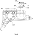
- the casing assembly 100 (specifically, the first casing 110) is further provided with a support table surface 140, the support table surface is located on an outer side of the accommodation slot 112 away from the accommodation cavity 111, and the flange portion 220 contacts with the support table surface 140 and is supported on the support table surface 140.
- the interface assembly 200 may be positioned and limited in the accommodation slot 112 by simply providing an opening suitable for the insertion of the main body portion 210, which is not only conducive to reducing an opening size of the accommodation slot 112 but also conducive to saving an assembly space of the interface assembly 200.
- FIG. 3 based on a structural form of the support table surface 140 abut against and support the flange portion 220, it is possible to quickly assemble the interface assembly 200 to the casing assembly 100 by means of an outside-to-inside assembly manner (i.e., from the outside of the casing assembly 100 towards its inside), and thus it is possible to efficiently reduce the difficulty of assembling the interface assembly 200.
- the support table surface 140 illustrated in FIG. 11 utilizes a dashed line wireframe only to indicate a relative position relationship between the support table surface 140 and the flange portion 220, and do not indicate a structural form and size of the support table surface 140.
- a sealant 500 is disposed between the flange portion 220 and the support table surface 140.
- the sealant 500 can not only secure the flange portion 220 to the support table surface 140, thereby securely assembling the interface assembly 200 in the accommodation slot 112.
- the sealant 500 may also fill a structural gap between the interface assembly 200 and the casing assembly 100 on the support table surface 140 to enhance the sealing property.
- the support table surface 140 is provided with an adhesive-accommodation slot (not shown in the figures), the flange portion 220 covers the adhesive-accommodation slot, and at least a portion of the sealant 500 is accommodated within the adhesive-accommodation slot.
- the adhesive-accommodation slot to accommodate the sealant 500 not only further enhances the stability and sealing of the connection between the interface assembly 200 and the casing assembly 100, but also, in an insertion direction of the interface assembly 200, a height difference between the interface assembly 200 and the casing assembly 100 may be reduced, thereby making a structure of the wearable device more compact and conducive to the miniaturized design of the wearable device.
- the adhesive-accommodation slot may also be disposed on the flange portion 220 or on both the flange portion 220 and the support table surface 140, which will not be repeated herein.
- the "insertion direction of the interface assembly 200 (hereinafter referred to as the "insertion direction") is defined herein mainly to illustrate a structural fit relationship between relevant components, and the insertion direction may be understood as a direction in which the interface assembly 200 is inserted and connected with the external plug, or a direction in which the interface assembly 200 is inserted into and removed from the accommodation slot 112 during disassembly and assembly (for example, a bold dotted line with double arrows in FIG. 3 indicates the insertion direction).
- the casing assembly 100 further includes a second casing 150 connected with the first casing 110.
- the second casing 150 is disposed to press and block the flange portion 220 from a side of the flange portion 220 that backs away from the support table surface 140, and the sealant 500 (or together with the adhesive-accommodation slot) is disposed between the second casing 150 and the flange portion 220.
- a position of the interface assembly 200 in the accommodation slot 112 or the casing assembly 100 may be effectively limited, and the possibility of the interface assembly 200 to be wobble or shift can be reduced, thereby improving the stability and reliability of the installation of the interface assembly 200.
- utilizing the second casing 150 to block the flange portion 220 may cause the flange portion 220 not to be exposed to the outside of the casing assembly 100, so that a user may not be able to see the flange portion 220 from the outside of the wearable device, which is conducive to enhancing the aesthetic appearance of the wearable device.
- flange portion 220 may adopt different shapes to accommodate the overall structural form of the interface assembly 200 or to meet different assembly requirements.
- the flange portion 220 is disposed in an annular structure (e.g., a regular annular or shaped annular structure), i.e., the flange portion 220 is disposed around an edge of the main body portion 210 on a side away from the accommodation cavity 111.
- the support table surface 140 may be disposed in an annular table structure around an edge of a side of the accommodation slot 112 away from the accommodation cavity 111 (i.e., a slot opening on the side of the accommodation slot 112 away from the accommodation cavity 111).
- the adhesive-accommodation slot may be disposed around the slot opening on the side of the accommodation slot 112 away from the accommodation cavity 111 and set on the support table surface 140, which allows for complete adhesive application around the accommodation slot 112 during the installation of the interface assembly 200 and forms the sealant 500, thereby effectively enhancing the sealing performance.
- the support table surface 140 may be an annular table structure disposed around the edge of the side of the accommodation slot 112 away from the accommodation cavity 111, or a plurality of support structures spaced apart around the slot opening of the side of the accommodation slot 112 away from the accommodation cavity 111.
- a multi-point fixed connection between the interface assembly 200 and the casing assembly 100 may be realized.
- the interface assembly 200 further includes a tongue portion 230, which is mainly used to establish an electrical connection relationship between the interface assembly 200 and the external plug.
- the tongue portion 230 includes a preset length in the insertion direction of the interface assembly 200, and correspondingly, the main body portion 210 is provided with a guiding cavity 210a.
- the guiding cavitya 210 extends from a side of the main body portion 210 proximate to the accommodation cavity 111 towards a side away from the accommodation cavity 111 and is in communication with an exterior of the interface assembly 200.
- tongue portion 230 While a portion of the tongue portion 230 is inserted into the guiding cavity 210a, another portion of the tongue portion 230 is disposed protruding from a side of the guiding cavity 210a away from the accommodation cavity 111 (it may also be understood that the tongue portion 230 is disposed protruding from a side of the flange portion 220 away from the accommodation cavity 111 in the insertion direction of the interface assembly 110).
- a length of the main body portion 210 in the insertion direction of the interface assembly 200 may be reduced, which is equivalent to reducing a length of the accommodation slot 200 and saving an assembly space of the interface assembly 200.
- an end surface of the tongue portion 230 backing away from the main body portion 210 in the insertion direction of the interface assembly 200 is defined as a first end surface
- an end surface of the flange portion 220 backing away from the main body portion 210 in the insertion direction of the interface assembly 200 is defined as a second end surface
- a height difference between the first end surface and the second end surface may be controlled to be in a range of 0.6 mm to 1.1 mm.
- the wearable device further includes a sealing member 600, which is mainly used to selectively block the interface assembly 200.
- a sealing member 600 which is mainly used to selectively block the interface assembly 200.
- impurities such as dust particles falling into the guiding cavity 210a or blocking the guiding cavity 210a may be reduced, thereby ensuring the normal usage of the interface assembly 200.
- the sealing member 600 can be removed to uncover the interface assembly 200.
- the sealing member 600 is arranged on the side of the main body 210 away from the accommodation cavity 111 and faces the guiding cavity 210a.
- a portion of the tongue portion 230 protruding from the guiding cavity 210a (hereinafter referred to as a protrusion portion of the tongue portion 230) may be utilized as a carrier for a fit connection between the interface assembly 200 and the sealing member 600, so as to position and assemble the sealing member 600 to the interface assembly 200 in a detachable or movable connection manner to block the interface assembly 200.
- the sealing member 600 may be fitted over the protrusion portion of the tongue portion 230 and cover the guiding cavity 210a.
- the main body portion 210 includes an inner casing 211 and an outer casing 212.
- the outer casing 212 is substantially a tubular body with a preset length in the insertion direction of the interface assembly 200, and a portion of the inner casing 211 is inserted within the outer casing 212 and the other portion of the inner casing 211 protrudes out of the outer casing 212.
- the inner casing 211 encloses the guiding cavity 210a.
- an inner space of the inner casing 211 is the guiding cavity 210a.
- one end of the inner casing 211 in the insertion direction of the interface assembly 200 is defined as a first end of the inner casing 211
- the other end of the inner casing 211 in the insertion direction of the interface assembly 200 is defined as a second end of the inner casing 211.
- the first end of the inner casing 211 is inserted into the outer casing 212 so as to form an adhesive-accommodation slot 210b for accommodating a waterproof adhesive between an inner side of the outer casing 212 and an outer side of the first end of the inner casing 211.
- the second end of the inner casing 211 is set protruding out from the outer casing 212 to form the flange portion 220.
- the flange portion 220 is formed by flanging the second end of the inner casing 211.
- the adhesive-accommodation space 210b and the guiding cavity 210a are formed inside the main body portion 210 and are isolated from each other along the insertion direction of the interface assembly 200, and the adhesive-accommodation space 210b is closer to the accommodation cavity 111 than the guiding cavity 210a, i.e., the adhesive-accommodation space 210b is located on the side of the guiding cavity 210a proximate to the accommodation cavity 111.
- the flange portion 220 is disposed to protrude only from the second end of the inner casing 211, for example, the flange portion 220 is formed by flanging the second end of the inner casing 211, but the flange portion 220 does not protrude from the outer casing 212.
- the inner casing 211 may be completely inserted inside the outer casing 212, or the second end of the inner casing 211 may be exposed outside the outer casing 212, so as to form interface assembly 200 in different structural forms to satisfy different requirements.
- a portion of the tongue portion 230 disposed within the guiding cavity 210a may extend via the first end of the inner casing 211 into the adhesive-accommodation space 210a, which establishes an electrical connection relationship between the interface assembly 200 and the circuit board 300 based on the cooperation between the tongue portion 230 and the wire assembly 400.
- a waterproof structure may be formed on a side of the main body portion 210 proximate to the accommodation cavity 111 by injecting the waterproof adhesive into the adhesive-accommodation space 210b, which not only effectively enhances the overall waterproof performance of the interface assembly 200, but also enhances the stability of the structural coordination between the outer casing 212 and the inner casing 211.
- the waterproof adhesive may be restricted to the outer side of the first end of the inner casing 211 through a sidewall of the outer casing 212, thereby effectively preventing the waterproof adhesive from overflowing.
- the flange portion 220 is utilized to hold the outer casing 212, thereby limiting a relative position between the outer casing 212 and the inner casing 211 as well as a volume and size of the adhesive-accommodation space 210b, thereby enhancing the structural strength of the main body portion 210, and even the interface assembly 200 as a whole.
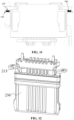
- the main body portion 210 further includes a reinforcement structure 213, which may be a plate-like structure soldered and secured to the first end of the inner casing 211 and disposed within the adhesive-accommodation space 210b, or may be a raised structure disposed on an outer surface of the first end of the inner casing 211, or the like.
- a reinforcement structure 213 which may be a plate-like structure soldered and secured to the first end of the inner casing 211 and disposed within the adhesive-accommodation space 210b, or may be a raised structure disposed on an outer surface of the first end of the inner casing 211, or the like.
- utilizing the reinforcement structure 213 not only enhances the structural strength of the inner casing 211 itself, but also enhances the connection strength between the inner casing 211 and the waterproof adhesive, and thus enhances the connection strength of the inner casing 211 and the outer casing 212, which enhances the structural stability and reliability of the main body portion 210 and the interface assembly 200.
- the disposed reinforcement structure 213 creates a condition for downsizing the interface assembly 200 as well as decreasing the requirement for the size of the accommodation slot 112.
- a wall thickness of the inner casing 211 and the outer casing 212 are usually set to be in a range of 0.3 mm and 0.4 mm, and a thickness of the waterproof adhesive (i.e., a thickness of the waterproof adhesive within the adhesive-accommodation space 210b in the insertion direction of the interface assembly 200) is usually set to about 0.7 mm.
- the wall thicknesses of the inner casing 211 and the outer casing 212 may be adjusted to be in a range of 0.1 mm and 0.3 mm (e.g., about 0.15 mm), while the thickness of the waterproof adhesive may be maintained at about 0.7 mm.
- the size of the interface assembly 200 may be reduced by reducing the wall thickness of the inner casing 211 and the outer casing 212, which in turn achieves the effect of saving the assembly space, and is more conducive to realizing the miniaturized design of the wearable device.
- an end of the tongue portion 230 that extends into the adhesive-accommodation space 210b may be fixedly connected (e.g., soldered) to the inner casing 211 with the aid of the reinforcement structure 213 to enhance the connection strength between the tongue portion 230 and the main body portion 210 and to further enhance the structural stability of the interface assembly 200.
- the interface assembly 200 further includes an external circuit board 240, which is disposed on the side of the main body portion 210 proximate to the accommodation cavity 111 (i.e., the side of the main body portion 210 backing away from the flange portion 220), and the interface assembly 200 is electrically connected to the wire assembly 400 via the external circuit board 240 and thus utilizes the wire assembly 400 to establish an electrical connection between the interface assembly 200 and the circuit board 300.
- an external circuit board 240 which is disposed on the side of the main body portion 210 proximate to the accommodation cavity 111 (i.e., the side of the main body portion 210 backing away from the flange portion 220), and the interface assembly 200 is electrically connected to the wire assembly 400 via the external circuit board 240 and thus utilizes the wire assembly 400 to establish an electrical connection between the interface assembly 200 and the circuit board 300.
- the circuit board 300 and circuits related to the interface assembly 200 may be transferred and disposed on the external circuit board 240, which not only reduces the size of the circuit board 300 and the requirement for the space of the accommodation cavity 111 and creates a condition for realizing the miniaturized design of the wearable device, but also realizes the integration of interface functions and facilitates the more reasonable setting of the accommodation cavity 111 and the accommodation slot 112, and enhances the flexibility of the assembly of the circuit board 300 and the interface assembly 200.
- the external circuit board 240 may be transversely arranged in the accommodation slot 112 relative to the circuit board 300, i.e., a plane on which the external circuit board 240 is located is intersected (e.g., vertically intersected) with a plane on which the circuit board 300 is located at an angle. In this way, the assembly space of the circuit board 300 and the interface assembly 200 may be further saved, and the full utilization of the structural space of the casing assembly 100 can be realized.
- a terminal pin of the tongue portion 230 is directly soldered to the external circuit board 240 to establish an electrical connection relationship between the tongue portion 230 and the external circuit board 240, and the external circuit board 240 is fixed on the side of the main body portion 210 proximate to the accommodation cavity 111 to build a complete structure with the interface assembly 200, so that the interface assembly 200 may be applied to the wearable device as an independent functional component.
- FIG. 1 and FIG. 3 only with the earphone as an example, but the earphone is only a specific embodiment of the wearable device, and the wearable device may also be a pair of glasses, a watch, or other devices.
Landscapes
- Engineering & Computer Science (AREA)
- Physics & Mathematics (AREA)
- Acoustics & Sound (AREA)
- Signal Processing (AREA)
- Health & Medical Sciences (AREA)
- Otolaryngology (AREA)
- Multimedia (AREA)
- General Health & Medical Sciences (AREA)
- Manufacturing & Machinery (AREA)
- Computer Hardware Design (AREA)
- General Physics & Mathematics (AREA)
- Electromagnetism (AREA)
- Theoretical Computer Science (AREA)
- Optics & Photonics (AREA)
- Microelectronics & Electronic Packaging (AREA)
- General Engineering & Computer Science (AREA)
- Human Computer Interaction (AREA)
- Neurosurgery (AREA)
- Ophthalmology & Optometry (AREA)
- Headphones And Earphones (AREA)
- Details Of Audible-Bandwidth Transducers (AREA)
- Circuit For Audible Band Transducer (AREA)
- Casings For Electric Apparatus (AREA)
- Audible-Bandwidth Dynamoelectric Transducers Other Than Pickups (AREA)
- Obtaining Desirable Characteristics In Audible-Bandwidth Transducers (AREA)
- Telephone Set Structure (AREA)
- Soundproofing, Sound Blocking, And Sound Damping (AREA)
Abstract
Description
- The present disclosure relates to the technical field of electronic devices, and in particular, to a wearable device.
- Wearable devices such as earphones and smart glasses have become indispensable tools in people's daily lives and work. A device interface, as a necessary component of wearable devices, primarily serves the function of data transmission with external devices and supplying power to the wearable devices through an electrical connection with an external power source. A structure and assembly manner of the device interface have a critical impact on the wearable devices.
- In related technology, a device interface is typically soldered directly to a mainboard of a wearable device. Assembling the mainboard with the soldered device interface into a casing of the wearable device necessitates a larger opening, which not only increases space requirements during assembly but also impedes the miniaturization of the wearable device.
- The main technical problem addressed by the present disclosure is to provide a wearable device intended to make the wearable device more compact and miniaturized.
- An embodiment provides a wearable device, comprising:
- a casing assembly, wherein the casing assembly includes a first casing, the first casing is provided with an accommodation slot and an accommodation cavity, and the accommodation slot is in communication with the accommodation cavity;
- an interface assembly, wherein the interface assembly is inserted into the accommodation slot;
- a circuit board, wherein the circuit board is disposed within the accommodation cavity; and
- a wire assembly, wherein the wire assembly is electrically connected with the circuit board and the interface assembly.
- In one embodiment, the interface assembly further includes:
- a main body portion, the main body portion being inserted into the accommodation slot; and
- a flange portion, the flange portion being provided on a side of the main body portion away from the accommodation cavity;
- the casing assembly is further provided with a support table surface, and the flange portion is supported by the support table surface.
- In one embodiment, the interface assembly further includes a tongue portion, the main body portion is provided with a guiding cavity; a portion of the tongue portion is inserted into the guiding cavity, and the other portion of the tongue portion protrudes out of the guiding cavity from the side of the main body portion away from the accommodation cavity.
- In one embodiment, an end surface of the tongue portion backing away from the main body portion along an insertion direction of the interface assembly is a first end surface, an end surface of the flange portion backing away from the main body portion along the insertion direction is a second end surface, and a height difference between the first end surface and the second end surface is in a range of 0.6 mm to 1.1 mm.
- In one embodiment, the wearable device further includes a sealing member, the sealing member being arranged on the side of the main body portion away from the accommodation cavity; the sealing member being cooperatively connected with the tongue portion for selectively blocking the interface assembly.
- In one embodiment, the interface assembly further includes an external circuit board, the external circuit board being disposed on a side of the main body portion proximate to the accommodation cavity, and the wire assembly is electrically connected with the external circuit board and the circuit board.
- In one embodiment, a plane on which the external circuit board is located and a plane on which the circuit board is located cross with each other.
- in one embodiment, the flange portion is disposed around an edge of the side of the main body portion away from the accommodation cavity;
- or, a count of the flange portion is set to be a plurality, a plurality of the flange portion being spaced apart around the edge of the side of the main body portion away from the accommodation cavity.
- In one embodiment, a sealant is provided between the flange portion and the support table surface.
- In one embodiment, the support table surface is provided with an adhesive-accommodation slot, the flange portion covers the adhesive-accommodation slot, and at least a portion of the sealant is accommodated within the adhesive-accommodation slot;
and/or the flange portion is provided with the adhesive-accommodation slot, the support table surface covers the adhesive-accommodation slot, and at least a portion of the sealant is accommodated within the adhesive-accommodation slot. - In one embodiment, the main body portion includes an inner casing and an outer casing, and the inner casing includes a first end and a second end opposite each other along an insertion direction of the interface assembly;
- the first end of the inner casing is inserted into the outer casing, and an adhesive-accommodation space for accommodating a waterproof adhesive is formed between the outer casing and the first end of the inner casing; and
- the second end of the inner casing protrudes out of the outer casing to form the flange portion.
- In one embodiment, the main body portion includes an inner casing and an outer casing, and the inner casing includes a first end and a second end opposite each other along an insertion direction of the interface assembly;
the first end of the inner casing is inserted into the outer casing, and an adhesive-accommodation space for accommodating a waterproof adhesive is formed between the outer casing and the first end of the inner casing, and the flange portion protrudes out of the second end of the inner casing. - In one embodiment, the main body portion further includes a reinforcement structure; the reinforcement structure is disposed at the first end of the inner casing and is located within the adhesive-accommodation space.
- In one embodiment, a wall thickness of the outer casing and/or the inner casing is in a range of 0.1mm to 0.3mm.
- In one embodiment, the casing assembly includes a first sidewall and a second sidewall connected at an angle, and a length of the first sidewall is greater than a length of the second sidewall, and the accommodation slot is provided in the second sidewall.
- In one embodiment, the wearable device is an earphone or a pair of glasses.
- The wearable device according to the above-described embodiment comprises a casing assembly, a circuit board, an interface assembly, and a wire assembly. The casing assembly is provided with an accommodation slot and an accommodation cavity, the circuit board is disposed in the accommodation cavity, and the interface assembly is inserted into the accommodation slot, and is electrically connected to the circuit board through the wire assembly. On the one hand, by setting the interface assembly separately from the circuit board and utilizing the wire assembly to establish an electrical connection between the interface assembly and the circuit board, a space occupied by the interface assembly on the circuit board can be reduced, which is conducive to reducing the size of the circuit board, adjusting a mounting position and mounting attitude of the interface assembly, and the overall miniaturized design of the wearable device may be realized. On the other hand, separating the interface assembly from the circuit board allows for the interface assembly to be mounted externally to the casing assembly, which helps reduce the size of the opening of the cavity in the wearable device and further conserves assembly space.
-
-
FIG. 1 is a schematic diagram illustrating an exemplary internal structure of a wearable device according to one embodiment of the present disclosure. -
FIG. 2 is a schematic diagram illustrating an exemplary internal structure of a casing assembly of a wearable device according to an embodiment of the present disclosure. -
FIG. 3 is a schematic diagram illustrating an assembly relationship between an interface assembly and a casing assembly of a wearable device according to an embodiment of the present disclosure. -
FIG. 4 is a schematic diagram (I) illustrating an exemplary three-dimensional structure of an interface assembly according to one embodiment of the present disclosure. -
FIG. 5 is a schematic diagram (II) illustrating an exemplary three-dimensional structure of an interface assembly according to one embodiment of the present disclosure. -
FIG. 6 is a schematic diagram illustrating an exemplary planar structure of an interface assembly according to one embodiment of the present disclosure. -
FIG. 7 is a schematic diagram (I) illustrating an exemplary structure of a flange portion of an interface assembly according to one embodiment of the present disclosure. -
FIG. 8 is a schematic diagram (II) illustrating an exemplary structure of a flange portion of an interface assembly according to one embodiment of the present disclosure. -
FIG. 9 is a schematic diagram (III) illustrating an exemplary structure of a flange portion of an interface assembly according to one embodiment of the present disclosure. -
FIG. 10 is a schematic diagram illustrating an exemplary cross-sectional structure of an interface assembly according to one embodiment of the present disclosure. -
FIG. 11 is a schematic diagram illustrating a fit relationship between structures of an interface assembly and a support table surface according to one embodiment of the present disclosure. -
FIG. 12 is a schematic diagram illustrating an exemplary structure of a reinforcement structure of an interface assembly according to one embodiment of the present disclosure. -
FIG. 13 is a schematic diagram illustrating a fit relationship between structures of an interface assembly and a sealing member according to one embodiment of the present disclosure. -
- 100, casing assembly; 110, first casing; 111, accommodation cavity; 112, accommodation slot; 120, first sidewall; 130, second sidewall; 140, support table surface; 150, second casing;
- 200, interface assembly; 210, main body portion; 210a, guiding cavity; 210b, adhesive-accommodation space; 211, inner casing; 212, outer casing; 213, reinforcement structure; 220, flange portion; 230, tongue portion; 240, external circuit board;
- 300, circuit board; 400, wire assembly; 500, sealant; and 600, sealing member.
- The present disclosure is described in further detail below by way of specific embodiments in conjunction with the accompanying drawings. Similar components in the different embodiments adopt associated similar component labeling. In the following embodiments, many of the details are described in order to enable the present disclosure to be better understood. However, a person skilled in the art will have no trouble recognizing that some of these features can be omitted in various embodiments or can be replaced by other components, materials, and methods. In some cases, some of the operations related to the present disclosure are not shown or described in the present disclosure, this is to prevent the core of the present disclosure from being overwhelmed by an excessive amount of description, and to a person skilled in the art, a detailed description of these related operations is not necessary, and they can fully understand the related operations according to the description in the present disclosure and the general technical knowledge in the field.
- Additionally, the features, operations, or characteristics described in the present disclosure may be combined in any appropriate manner to form various embodiments. Also, the various steps or actions in the description of the method may be switched or adjusted in order in a manner that would be apparent to a person skilled in the art. The various sequences in the present disclosure and the accompanying drawings are therefore only intended to clearly describe a particular embodiment, and do not purport to be a required sequence unless otherwise indicated that one of the sequences must be followed.
- The serial numbers themselves, such as "first", "second", etc., are used herein only to distinguish the objects described, and have no sequential or technical meaning. The terms "connection" and "coupling" in the present disclosure include direct and indirect connections (couplings) unless otherwise specified.
- Referring to
FIGs. 1 to 3 , an embodiment of the present disclosure provides a wearable device, such as an earphone, a pair of glasses, a watch, a bracelet, or the like. The wearable device includes acasing assembly 100, aninterface assembly 200, acircuit board 300, awire assembly 400, and other functional components present as needed (e.g., a microphone assembly, a speaker assembly, a button assembly, a voice coil assembly, a battery assembly, etc. realizing functions related to open-ear Bluetooth headphones). A detailed description may be referred to descriptions below. - The
case assembly 100 is mainly used as a mounting carrier for theinterface assembly 200, thecircuit board 300, and other functional components, and it is to be understood that thecase assembly 100 is a collection of related components constituting an overall contour form of the wearable device. With the help of thecasing assembly 100, the wearable device may be moved, carried, worn, operated, and used. - The
circuit board 300 is disposed within thecasing assembly 100, and thecircuit board 300 may be understood as a main control board or a main board of the wearable device, which serves as a regulating and managing board for all or some of the functional components in the wearable device. For example, when the wearable device is an earphone, thecircuit board 300 is used in the earphone for converting and processing an electrical signal to support the realization of various functions of the earphone (e.g., to support the earphone to realize switching on and off, switching playback contents, increasing and decreasing a volume, etc.). - The
interface assembly 200 is disposed in thecasing assembly 100, for example, theinterface assembly 200 is disposed within thecasing assembly 100 in such a manner that an interface end of theinterface assembly 200 is exposed outside thecasing assembly 100. Theinterface assembly 200 may be used for connecting to an external power source for charging the wearable device. Theinterface assembly 200 may also be used for connecting to an external device (e.g., a cell phone, a computer, etc.) for data transmission between the external device and the wearable device. For example, theinterface assembly 200 may be a Type-C interface, a USB interface, a magnetic interface, a Lighting interface, etc., which is selected according to actual needs and is not limited herein. - In one embodiment, referring to
FIG. 1 and FIG. 2 , thecasing assembly 100 includes afirst casing 110, thefirst casing 110 being provided with anaccommodation cavity 111 and anaccommodation slot 112 that are in communication with each other. Thecircuit board 300 is disposed within theaccommodation cavity 111, theinterface assembly 200 is inserted in theaccommodation slot 112, and thewire assembly 400 is electrically connected between thecircuit board 300 and theinterface assembly 200. - For example, the
wire assembly 400 is a wire, a row of wires, a flexible printed circuit (FPC), etc., which is selected according to the actual needs and is not limited herein. - It should be noted that a bold solid line in
FIG.1 to represent thewire assembly 400 is only to reflect the existence of an electrical connection relationship between thecircuit board 300, theinterface assembly 200, and thewire assembly 400, and does not indicate a specific structure and layout of thewire assembly 400, nor does it indicate a structural configuration of thewire assembly 400 in connection with thecircuit board 300 and theinterface assembly 200. - First, compared to the related technology in which the
interface assembly 200 is directly soldered to thecircuit board 300, by separately setting theinterface assembly 200 and thecircuit board 300 in thecasing assembly 100, and utilizing thewire assembly 400 to electrically connect thecircuit board 300 and theinterface assembly 200, this not only can effectively improve a freedom degree of an installation position and installation posture of theinterface assembly 200 and thecircuit board 300, but also can reduce a requirement of theinterface assembly 200 and thecircuit board 300 for a specific size and shape for an assembly space, thereby flexibly adjusting positions and forms of thecircuit board 300, theaccommodation cavity 111, theinterface assembly 200, and theaccommodation slot 112, etc. based on an overall structural architecture of the wearable device, and creating a favorable condition for reducing a difficulty of assembling the wearable device. - Second, with an electrical connection relationship established between the
circuit board 300 and theinterface assembly 200 through thewire assembly 400, thecircuit board 300 and theinterface assembly 200 may be disposed, in the form of a certain spacing between each other, in theaccommodation cavity 111 and theaccommodation slot 112, respectively. Such arrangement can effectively reduce a space occupied by theinterface assembly 200 on theaccommodation cavity 111 or an assembly space of thecircuit board 300, thereby reducing the possibility of interference of theinterface assembly 200 on thecircuit board 300, subsequently improving the effectiveness and stability of the operation of theinterface assembly 200 and thecircuit board 300, and improving the reliability and service life of the wearable device. - Third, the
interface assembly 200 and thecircuit board 300 are disposed in different assembly spaces, respectively, (i.e., theaccommodation slot 112 and the accommodation cavity 111), and cavity openings corresponding to theinterface assembly 200 and thecircuit board 300 may be disposed in thecasing assembly 100, which is conducive to reducing an opening size of thecasing assembly 100 and saving the assembly space, thus creating a condition for enhancing the compactness of the wearable device and realizing the miniaturized design of the wearable device. The smaller opening size also effectively ensures the structural strength of a cavity and even thecasing assembly 100, and facilitates the respective installation of theinterface assembly 200 and the circuit board 300 (e.g., using an assembly manner where theinterface assembly 200 is inserted into theaccommodation slot 112 from the outside to the inside), thereby effectively reducing the assembly difficulty of theinterface assembly 200, thecircuit board 300, and even the wearable device. - In one embodiment, referring to
FIG. 2 in connection withFIG. 1 , the casing assembly 100 (specifically, the first casing 110) includes afirst sidewall 120 and asecond sidewall 130 connected at an angle. A length of thefirst sidewall 120 is greater than a length of thesecond sidewall 130, which may be interpreted to mean that a length of thefirst sidewall 120 is a length direction of the wearable device or thefirst casing 110, and a length direction of thesecond sidewall 130 may be in a same direction as a width direction of the wearable device or the first casing 110 (i.e., thefirst sidewall 120 and thesecond sidewall 130 are connected at an approximate right angle). A length direction of thesecond sidewall 130 may also be in a direction with a certain deflection angle relative to the width direction of the wearable device (or the first casing 110) (i.e., thefirst sidewall 120 and thesecond sidewall 130 are connected at an approximate acute angle or an approximate obtuse angle). - Taking an open-ear Bluetooth headphone as the wearable device as an example, the
first sidewall 120 and thesecond sidewall 130 may be two sidewalls in thecasing assembly 100 that are away from an ear-hanging portion of the earphone and abut against each other. Theaccommodation slot 112, on the other hand, is disposed in thesecond sidewall 130, i.e.,interface assembly 200 is disposed in a width direction of thecasing assembly 100 or the wearable device. - Similarly, taking a non-open-ear Bluetooth headphone as the wearable device as an example, the
interface assembly 200 and other functional components (e.g., a button component) are usually disposed in a length direction of the earphone in the art, which increases the requirement for a length of the earphone (e.g., increasing a length of a relevant cavity structure within thecasing assembly 100 and a length of the first sidewall 120) and is not conducive to the miniaturized design of the earphone. - In the present embodiment, by adjusting the
interface assembly 200 to be disposed in the width direction of the wearable device, the requirement for the dimension of thecasing assembly 100 or a cavity structure within thecasing assembly 100 in a length direction of the wearable device may be effectively reduced, so that a smaller cavity structure (e.g., the accommodation slot 112) may be disposed within thecasing assembly 100 to realize the assembly of functional components such as theinterface assembly 200, thecircuit board 300, etc., thereby facilitating the miniaturized and compact design of the wearable device. - In some embodiments, referring to
FIG. 2 , an angle between thefirst sidewall 120 and thesecond sidewall 130 is obtuse, which reduces the size of the wearable device in the width direction, so that the accommodation slot 112 (together with the interface assembly 200) exhibits a structural form that is inclinedly disposed with respect to thefirst sidewall 120, which is conducive to enhancing the structural compactness of the wearable device. - Of course, according to an overall contour form of the wearable device and the needs of the structural setup, the angle between the
first sidewall 120 and thesecond sidewall 130 may also be set at a right angle, an acute angle, or the like, and is not limited herein. - It should be noted that a bold dotted line in
FIG. 2 to indicate thefirst sidewall 120 and thesecond sidewall 130 is merely to show an approximate position and direction of thefirst sidewall 120 and thesecond sidewall 130 in thecasing assembly 100, and does not represent the structural forms and sizes, etc., of thefirst sidewall 120 and thesecond sidewall 130. Meanwhile, a bold solid line with double arrows utilized inFIG. 2 illustrates the length direction and width direction of the whole wearable device. - In other embodiments, referring to
FIG. 3 , based on an implementation principle that theinterface assembly 200 is disposed separately from thecircuit board 300, the accommodation slot 112 (together with the interface assembly 200) is disposed in thefirst sidewall 120 to meet different design requirements, which will not be repeated herein. - The following describes the
interface assembly 200 and structures associated with theinterface assembly 200, and other portions of the wearable device may be referred to in the prior art. - In one embodiment, referring to
FIG. 1 to FIG. 11 , theinterface assembly 200 includes amain body portion 210 and aflange portion 220. Themain body portion 210 is inserted into theaccommodation slot 112 and mainly serves as a carrier for inserting and connecting theinterface assembly 200 to an external plug (e.g., a power supply plug of an external power source, a data plug of an external device, etc.). Theflange portion 220 is disposed on a side of themain body portion 210 away from theaccommodation cavity 111. Accordingly, the casing assembly 100 (specifically, the first casing 110) is further provided with asupport table surface 140, the support table surface is located on an outer side of theaccommodation slot 112 away from theaccommodation cavity 111, and theflange portion 220 contacts with thesupport table surface 140 and is supported on thesupport table surface 140. - On the one hand, by utilizing a fit relationship between the
flange portion 220 and thesupport table surface 140, theinterface assembly 200 may be positioned and limited in theaccommodation slot 112 by simply providing an opening suitable for the insertion of themain body portion 210, which is not only conducive to reducing an opening size of theaccommodation slot 112 but also conducive to saving an assembly space of theinterface assembly 200. - On the other hand, please refer to
FIG. 3 , based on a structural form of thesupport table surface 140 abut against and support theflange portion 220, it is possible to quickly assemble theinterface assembly 200 to thecasing assembly 100 by means of an outside-to-inside assembly manner (i.e., from the outside of thecasing assembly 100 towards its inside), and thus it is possible to efficiently reduce the difficulty of assembling theinterface assembly 200. - It should be noted that the
support table surface 140 illustrated inFIG. 11 utilizes a dashed line wireframe only to indicate a relative position relationship between thesupport table surface 140 and theflange portion 220, and do not indicate a structural form and size of thesupport table surface 140. - Further, referring to
FIG. 11 , asealant 500 is disposed between theflange portion 220 and thesupport table surface 140. Thesealant 500 can not only secure theflange portion 220 to thesupport table surface 140, thereby securely assembling theinterface assembly 200 in theaccommodation slot 112. At the same time, thesealant 500 may also fill a structural gap between theinterface assembly 200 and thecasing assembly 100 on thesupport table surface 140 to enhance the sealing property. - In some embodiments, the
support table surface 140 is provided with an adhesive-accommodation slot (not shown in the figures), theflange portion 220 covers the adhesive-accommodation slot, and at least a portion of thesealant 500 is accommodated within the adhesive-accommodation slot. Using the adhesive-accommodation slot to accommodate thesealant 500 not only further enhances the stability and sealing of the connection between theinterface assembly 200 and thecasing assembly 100, but also, in an insertion direction of theinterface assembly 200, a height difference between theinterface assembly 200 and thecasing assembly 100 may be reduced, thereby making a structure of the wearable device more compact and conducive to the miniaturized design of the wearable device. - The adhesive-accommodation slot may also be disposed on the
flange portion 220 or on both theflange portion 220 and thesupport table surface 140, which will not be repeated herein. - It should be noted that the "insertion direction of the interface assembly 200 (hereinafter referred to as the "insertion direction") is defined herein mainly to illustrate a structural fit relationship between relevant components, and the insertion direction may be understood as a direction in which the
interface assembly 200 is inserted and connected with the external plug, or a direction in which theinterface assembly 200 is inserted into and removed from theaccommodation slot 112 during disassembly and assembly (for example, a bold dotted line with double arrows inFIG. 3 indicates the insertion direction). - In other embodiments, referring to
FIG. 2 andFIG. 11 , thecasing assembly 100 further includes asecond casing 150 connected with thefirst casing 110. Thesecond casing 150 is disposed to press and block theflange portion 220 from a side of theflange portion 220 that backs away from thesupport table surface 140, and the sealant 500 (or together with the adhesive-accommodation slot) is disposed between thesecond casing 150 and theflange portion 220. - Thereby, by pressing and clamping the
flange portion 220 between thesupport table surface 140 and thesecond casing 150, a position of theinterface assembly 200 in theaccommodation slot 112 or thecasing assembly 100 may be effectively limited, and the possibility of theinterface assembly 200 to be wobble or shift can be reduced, thereby improving the stability and reliability of the installation of theinterface assembly 200. - At the same time, utilizing the
second casing 150 to block theflange portion 220 may cause theflange portion 220 not to be exposed to the outside of thecasing assembly 100, so that a user may not be able to see theflange portion 220 from the outside of the wearable device, which is conducive to enhancing the aesthetic appearance of the wearable device. - Further, the
flange portion 220 may adopt different shapes to accommodate the overall structural form of theinterface assembly 200 or to meet different assembly requirements. - By way of example, referring to
FIG. 7 and FIG. 8 , theflange portion 220 is disposed in an annular structure (e.g., a regular annular or shaped annular structure), i.e., theflange portion 220 is disposed around an edge of themain body portion 210 on a side away from theaccommodation cavity 111. Accordingly, thesupport table surface 140 may be disposed in an annular table structure around an edge of a side of theaccommodation slot 112 away from the accommodation cavity 111 (i.e., a slot opening on the side of theaccommodation slot 112 away from the accommodation cavity 111). - As a result, a contact area between the
support table surface 140 and theflange portion 220 may be effectively increased and thesupport table surface 140 may provide an even and reliable support force to theinterface assembly 200. In terms of the adhesive-accommodation slot, the adhesive-accommodation slot may be disposed around the slot opening on the side of theaccommodation slot 112 away from theaccommodation cavity 111 and set on thesupport table surface 140, which allows for complete adhesive application around theaccommodation slot 112 during the installation of theinterface assembly 200 and forms thesealant 500, thereby effectively enhancing the sealing performance. - By way of example, referring to
FIG. 9 , there are a plurality of flange portions 220 (e.g., two, three, or some other greater number). The plurality offlange portions 220 spaced apart around an edge of a side of themain body portion 210 away from theaccommodation cavity 111. Compatibly, thesupport table surface 140 may be an annular table structure disposed around the edge of the side of theaccommodation slot 112 away from theaccommodation cavity 111, or a plurality of support structures spaced apart around the slot opening of the side of theaccommodation slot 112 away from theaccommodation cavity 111. - Thereby, based on the count of the
flange portions 220 and an arrangement form, a multi-point fixed connection between theinterface assembly 200 and thecasing assembly 100 may be realized. It can be understood that generally speaking, the larger the contact area between thesupport surface 140 and theflange portion 220 is, the more stable the assembly of theinterface assembly 200 is. Therefore, structural forms of theflange portion 220 and thesupport table surface 140 and a fit relationship between theflange portion 220 and thesupport table surface 140 may be flexibly selected according to actual needs, which will not be repeated herein. - In one embodiment, referring to
FIG. 3 ,FIG. 4 , andFIG. 6 toFIG. 13 , theinterface assembly 200 further includes atongue portion 230, which is mainly used to establish an electrical connection relationship between theinterface assembly 200 and the external plug. Thetongue portion 230 includes a preset length in the insertion direction of theinterface assembly 200, and correspondingly, themain body portion 210 is provided with a guidingcavity 210a. The guidingcavitya 210 extends from a side of themain body portion 210 proximate to theaccommodation cavity 111 towards a side away from theaccommodation cavity 111 and is in communication with an exterior of theinterface assembly 200. While a portion of thetongue portion 230 is inserted into the guidingcavity 210a, another portion of thetongue portion 230 is disposed protruding from a side of the guidingcavity 210a away from the accommodation cavity 111 (it may also be understood that thetongue portion 230 is disposed protruding from a side of theflange portion 220 away from theaccommodation cavity 111 in the insertion direction of the interface assembly 110). - By setting the
tongue portion 230 protruding out of the guidingcavity 111, a length of themain body portion 210 in the insertion direction of theinterface assembly 200 may be reduced, which is equivalent to reducing a length of theaccommodation slot 200 and saving an assembly space of theinterface assembly 200. - In some specific embodiments, for ease of differentiation and description, see
FIG. 6 , an end surface of thetongue portion 230 backing away from themain body portion 210 in the insertion direction of theinterface assembly 200 is defined as a first end surface, and an end surface of theflange portion 220 backing away from themain body portion 210 in the insertion direction of theinterface assembly 200 is defined as a second end surface, and a height difference between the first end surface and the second end surface may be controlled to be in a range of 0.6 mm to 1.1 mm. - Thereby, in the case where the length of the
tongue portion 230 is limited and cannot be changed, by selectively setting a height difference between thetongue portion 230 and theflange portion 220, it is possible to not only ensure an insertion strength between theinterface assembly 200 and the external plug, and can also create a condition for reducing the size of theaccommodation slot 200 and saving the assembly space of theinterface assembly 200. - Further, referring to
FIG. 13 , the wearable device further includes a sealingmember 600, which is mainly used to selectively block theinterface assembly 200. For example, when theinterface assembly 200 is not plugged into a corresponding external plug, by blocking theinterface assembly 200 with the sealingmember 600, impurities such as dust particles falling into the guidingcavity 210a or blocking the guidingcavity 210a may be reduced, thereby ensuring the normal usage of theinterface assembly 200. When theinterface assembly 200 needs to be used, the sealingmember 600 can be removed to uncover theinterface assembly 200. - Specifically, the sealing
member 600 is arranged on the side of themain body 210 away from theaccommodation cavity 111 and faces the guidingcavity 210a. A portion of thetongue portion 230 protruding from the guidingcavity 210a (hereinafter referred to as a protrusion portion of the tongue portion 230) may be utilized as a carrier for a fit connection between theinterface assembly 200 and the sealingmember 600, so as to position and assemble the sealingmember 600 to theinterface assembly 200 in a detachable or movable connection manner to block theinterface assembly 200. For example, the sealingmember 600 may be fitted over the protrusion portion of thetongue portion 230 and cover the guidingcavity 210a. - In one embodiment, see
FIG. 5, FIG. 6 , andFIG. 10 , themain body portion 210 includes aninner casing 211 and anouter casing 212. Theouter casing 212 is substantially a tubular body with a preset length in the insertion direction of theinterface assembly 200, and a portion of theinner casing 211 is inserted within theouter casing 212 and the other portion of theinner casing 211 protrudes out of theouter casing 212. Theinner casing 211 encloses the guidingcavity 210a. In some embodiments, an inner space of theinner casing 211 is the guidingcavity 210a. - More specifically, for ease of distinction and description, one end of the
inner casing 211 in the insertion direction of theinterface assembly 200 is defined as a first end of theinner casing 211, and the other end of theinner casing 211 in the insertion direction of theinterface assembly 200 is defined as a second end of theinner casing 211. The first end of theinner casing 211 is inserted into theouter casing 212 so as to form an adhesive-accommodation slot 210b for accommodating a waterproof adhesive between an inner side of theouter casing 212 and an outer side of the first end of theinner casing 211. The second end of theinner casing 211 is set protruding out from theouter casing 212 to form theflange portion 220. In a specific implementation, theflange portion 220 is formed by flanging the second end of theinner casing 211. - It can also be understood that the adhesive-
accommodation space 210b and the guidingcavity 210a are formed inside themain body portion 210 and are isolated from each other along the insertion direction of theinterface assembly 200, and the adhesive-accommodation space 210b is closer to theaccommodation cavity 111 than the guidingcavity 210a, i.e., the adhesive-accommodation space 210b is located on the side of the guidingcavity 210a proximate to theaccommodation cavity 111. - In other embodiments, in terms of the
flange portion 220, theflange portion 220 is disposed to protrude only from the second end of theinner casing 211, for example, theflange portion 220 is formed by flanging the second end of theinner casing 211, but theflange portion 220 does not protrude from theouter casing 212. At this time, theinner casing 211 may be completely inserted inside theouter casing 212, or the second end of theinner casing 211 may be exposed outside theouter casing 212, so as to forminterface assembly 200 in different structural forms to satisfy different requirements. - In some embodiments, a portion of the
tongue portion 230 disposed within the guidingcavity 210a may extend via the first end of theinner casing 211 into the adhesive-accommodation space 210a, which establishes an electrical connection relationship between theinterface assembly 200 and thecircuit board 300 based on the cooperation between thetongue portion 230 and thewire assembly 400. - Using the adhesive-
accommodation space 210b as an accommodation space for the waterproof adhesive, a waterproof structure may be formed on a side of themain body portion 210 proximate to theaccommodation cavity 111 by injecting the waterproof adhesive into the adhesive-accommodation space 210b, which not only effectively enhances the overall waterproof performance of theinterface assembly 200, but also enhances the stability of the structural coordination between theouter casing 212 and theinner casing 211. In a process of dispensing the adhesive into the adhesive-accommodation space 210b, the waterproof adhesive may be restricted to the outer side of the first end of theinner casing 211 through a sidewall of theouter casing 212, thereby effectively preventing the waterproof adhesive from overflowing. At the same time, in some embodiments, theflange portion 220 is utilized to hold theouter casing 212, thereby limiting a relative position between theouter casing 212 and theinner casing 211 as well as a volume and size of the adhesive-accommodation space 210b, thereby enhancing the structural strength of themain body portion 210, and even theinterface assembly 200 as a whole. - Furthermore, referring to
FIG. 12 andFIG. 10 , themain body portion 210 further includes areinforcement structure 213, which may be a plate-like structure soldered and secured to the first end of theinner casing 211 and disposed within the adhesive-accommodation space 210b, or may be a raised structure disposed on an outer surface of the first end of theinner casing 211, or the like. - On the one hand, utilizing the
reinforcement structure 213 not only enhances the structural strength of theinner casing 211 itself, but also enhances the connection strength between theinner casing 211 and the waterproof adhesive, and thus enhances the connection strength of theinner casing 211 and theouter casing 212, which enhances the structural stability and reliability of themain body portion 210 and theinterface assembly 200. - On the other hand, the disposed
reinforcement structure 213 creates a condition for downsizing theinterface assembly 200 as well as decreasing the requirement for the size of theaccommodation slot 112. For example, in general, in order to make themain body portion 210 have sufficient structural strength and good waterproof performance, a wall thickness of theinner casing 211 and theouter casing 212 are usually set to be in a range of 0.3 mm and 0.4 mm, and a thickness of the waterproof adhesive (i.e., a thickness of the waterproof adhesive within the adhesive-accommodation space 210b in the insertion direction of the interface assembly 200) is usually set to about 0.7 mm. - However, with the
reinforcement structure 213, the wall thicknesses of theinner casing 211 and theouter casing 212 may be adjusted to be in a range of 0.1 mm and 0.3 mm (e.g., about 0.15 mm), while the thickness of the waterproof adhesive may be maintained at about 0.7 mm. Thereby, the size of theinterface assembly 200 may be reduced by reducing the wall thickness of theinner casing 211 and theouter casing 212, which in turn achieves the effect of saving the assembly space, and is more conducive to realizing the miniaturized design of the wearable device. - In some embodiments, referring to
FIG. 12 , with respect to thetongue portion 230, an end of thetongue portion 230 that extends into the adhesive-accommodation space 210b may be fixedly connected (e.g., soldered) to theinner casing 211 with the aid of thereinforcement structure 213 to enhance the connection strength between thetongue portion 230 and themain body portion 210 and to further enhance the structural stability of theinterface assembly 200. - In one embodiment, referring to
FIG. 3 to FIG. 6 andFIG. 10 , theinterface assembly 200 further includes anexternal circuit board 240, which is disposed on the side of themain body portion 210 proximate to the accommodation cavity 111 (i.e., the side of themain body portion 210 backing away from the flange portion 220), and theinterface assembly 200 is electrically connected to thewire assembly 400 via theexternal circuit board 240 and thus utilizes thewire assembly 400 to establish an electrical connection between theinterface assembly 200 and thecircuit board 300. - With the
external circuit board 240, thecircuit board 300 and circuits related to the interface assembly 200 (such as a voltage and current regulator circuit, etc.) may be transferred and disposed on theexternal circuit board 240, which not only reduces the size of thecircuit board 300 and the requirement for the space of theaccommodation cavity 111 and creates a condition for realizing the miniaturized design of the wearable device, but also realizes the integration of interface functions and facilitates the more reasonable setting of theaccommodation cavity 111 and theaccommodation slot 112, and enhances the flexibility of the assembly of thecircuit board 300 and theinterface assembly 200. - As far as the wearable device is concerned, please refer to
FIG. 1 andFIG. 3 , theexternal circuit board 240 may be transversely arranged in theaccommodation slot 112 relative to thecircuit board 300, i.e., a plane on which theexternal circuit board 240 is located is intersected (e.g., vertically intersected) with a plane on which thecircuit board 300 is located at an angle. In this way, the assembly space of thecircuit board 300 and theinterface assembly 200 may be further saved, and the full utilization of the structural space of thecasing assembly 100 can be realized. - In some embodiments, with respect to the
tongue portion 230, a terminal pin of thetongue portion 230 is directly soldered to theexternal circuit board 240 to establish an electrical connection relationship between thetongue portion 230 and theexternal circuit board 240, and theexternal circuit board 240 is fixed on the side of themain body portion 210 proximate to theaccommodation cavity 111 to build a complete structure with theinterface assembly 200, so that theinterface assembly 200 may be applied to the wearable device as an independent functional component. - It is to be noted that the broad structural construction of the wearable device of the embodiments of the present disclosure is shown in
FIG. 1 andFIG. 3 only with the earphone as an example, but the earphone is only a specific embodiment of the wearable device, and the wearable device may also be a pair of glasses, a watch, or other devices. - The above application of specific examples to illustrate the present disclosure is only used to assist in understanding the present disclosure and is not intended to limit the present disclosure. For those skilled in the art to which the present disclosure belongs, a number of simple deductions, deformations, or substitutions may also be made based on the ideas of the present disclosure.
Claims (16)
- A wearable device, comprising:a casing assembly including a first casing, wherein the first casing is provided with an accommodation slot and an accommodation cavity, and the accommodation slot is in communication with the accommodation cavity;an interface assembly inserted into the accommodation slot;a circuit board disposed within the accommodation cavity; anda wire assembly electrically connected with the circuit board and the interface assembly.
- The wearable device of claim 1, wherein the interface assembly includes:a main body portion inserted into the accommodation slot; anda flange portion disposed on a side of the main body portion away from the accommodation cavity; whereinthe casing assembly is further provided with a support table surface, and the flange portion is supported by the support table surface.
- The wearable device of claim 2, wherein the interface assembly further includes a tongue portion, the main body portion is provided with a guiding cavity, a portion of the tongue portion is inserted into the guiding cavity, and the other portion of the tongue portion protrudes out of the guiding cavity from the side of the main body portion away from the accommodation cavity.
- The wearable device of claim 3, wherein an end surface of the tongue portion backing away from the main body portion along an insertion direction of the interface assembly is a first end surface, an end surface of the flange portion backing away from the main body portion along the insertion direction is a second end surface, and a height difference between the first end surface and the second end surface is in a range of 0.6 mm to 1.1 mm.
- The wearable device of claim 3, further comprising a sealing member, the sealing member being arranged on the side of the main body portion away from the accommodation cavity, the sealing member being cooperatively connected with the tongue portion for selectively blocking the interface assembly.
- The wearable device of claim 2, wherein the interface assembly further includes an external circuit board, the external circuit board being disposed on a side of the main body portion proximate to the accommodation cavity, the wire assembly being electrically connected with the external circuit board and the circuit board.
- The wearable device of claim 6, wherein a plane on which the external circuit board is located and a plane on which the circuit board is located are intersected with each other.
- The wearable device of claim 2, wherein the flange portion is disposed around an edge of the side of the main body portion away from the accommodation cavity; or
there are a plurality of flange portions, the plurality of flange portions being spaced apart around the edge of the side of the main body portion away from the accommodation cavity. - The wearable device of claim 2, wherein a sealant is disposed between the flange portion and the support table surface.
- The wearable device of claim 9, wherein the support table surface is provided with an adhesive-accommodation slot, the flange portion covers the adhesive-accommodation slot, and at least a portion of the sealant is accommodated within the adhesive-accommodation slot; and/or
the flange portion is provided with the adhesive-accommodation slot, the support table surface covers the adhesive-accommodation slot, and at least a portion of the sealant is accommodated within the adhesive-accommodation slot. - The wearable device of claim 2, wherein the main body portion includes an inner casing and an outer casing, and the inner casing includes a first end and a second end opposite each other along the insertion direction of the interface assembly;the first end of the inner casing is inserted into the outer casing, and an adhesive-accommodation space for accommodating a waterproof adhesive is formed between the outer casing and the first end of the inner casing; andthe second end of the inner casing protrudes out of the outer casing to form the flange portion.
- The wearable device of claim 2, wherein the main body portion includes an inner casing and an outer casing, and the inner casing includes a first end and a second end opposite each other along an insertion direction of the interface assembly;
the first end of the inner casing is inserted into the outer casing, and an adhesive-accommodation space for accommodating a waterproof adhesive is formed between the outer casing and the first end of the inner casing, and the flange portion protrudes out of the second end of the inner casing. - The wearable device of claim 11 or 12, wherein the main body portion further includes a reinforcement structure, and the reinforcement structure is disposed at the first end of the inner casing and is located within the adhesive-accommodation space.
- The wearable device of claim 13, wherein a wall thickness of the outer casing and/or the inner casing is in a range of 0.1 mm to 0.3 mm.
- The wearable device of any one of claims 1 to 12, wherein the casing assembly includes a first sidewall and a second sidewall connected at an angle, a length of the first sidewall is greater than a length of the second sidewall, and the accommodation slot is disposed in the second sidewall.
- The wearable device of any one of claims 1 to 12, wherein the wearable device is an earphone or a pair of glasses.
Applications Claiming Priority (2)
| Application Number | Priority Date | Filing Date | Title |
|---|---|---|---|
| CN202310541798 | 2023-05-12 | ||
| PCT/CN2024/077618 WO2024234758A1 (en) | 2023-05-12 | 2024-02-19 | Wearable device |
Publications (2)
| Publication Number | Publication Date |
|---|---|
| EP4496347A1 true EP4496347A1 (en) | 2025-01-22 |
| EP4496347A4 EP4496347A4 (en) | 2025-08-20 |
Family
ID=91784493
Family Applications (22)
| Application Number | Title | Priority Date | Filing Date |
|---|---|---|---|
| EP25178895.6A Pending EP4611394A3 (en) | 2023-05-12 | 2023-08-08 | Wearing component and earphone |
| EP25188401.1A Pending EP4633193A3 (en) | 2023-05-12 | 2023-08-08 | Earphone |
| EP25187733.8A Pending EP4629661A3 (en) | 2023-05-12 | 2023-08-08 | Earphone |
| EP23937160.2A Pending EP4629659A4 (en) | 2023-05-12 | 2023-08-08 | HEADPHONES |
| EP25188417.7A Pending EP4633194A3 (en) | 2023-05-12 | 2023-08-08 | Earphone |
| EP23937159.4A Pending EP4626019A4 (en) | 2023-05-12 | 2023-08-08 | HEADPHONES |
| EP25187740.3A Pending EP4629662A3 (en) | 2023-05-12 | 2023-08-08 | HEADPHONES |
| EP23937161.0A Pending EP4607951A4 (en) | 2023-05-12 | 2023-08-08 | PORT AND EARPHONE COMPONENT |
| EP23937213.9A Pending EP4611389A4 (en) | 2023-05-12 | 2023-10-11 | ACOUSTIC DEVICE |
| EP23937228.7A Pending EP4607958A4 (en) | 2023-05-12 | 2023-10-23 | LOUDSPEAKER ARRANGEMENT AND PORTABLE ELECTRONIC DEVICE |
| EP23937229.5A Pending EP4568274A4 (en) | 2023-05-12 | 2023-10-23 | HEADPHONES |
| EP23937293.1A Pending EP4583532A4 (en) | 2023-05-12 | 2023-12-05 | ACOUSTIC OUTPUT DEVICE |
| EP23937318.6A Pending EP4614999A4 (en) | 2023-05-12 | 2023-12-20 | ELECTRONIC DEVICE |
| EP25178483.1A Pending EP4607953A3 (en) | 2023-05-12 | 2023-12-20 | Earphones |
| EP23937320.2A Pending EP4598055A4 (en) | 2023-05-12 | 2023-12-20 | VIBRATION TRANSMISSION FILM, BONE CONDITIONING SPEAKERS AND HEADPHONES |
| EP23937321.0A Pending EP4604569A4 (en) | 2023-05-12 | 2023-12-20 | HEADPHONES |
| EP23937319.4A Pending EP4598049A4 (en) | 2023-05-12 | 2023-12-20 | Earphone |
| EP25183915.5A Pending EP4601328A3 (en) | 2023-05-12 | 2023-12-20 | Earphone |
| EP25178469.0A Pending EP4607952A3 (en) | 2023-05-12 | 2023-12-20 | Earphones |
| EP25174914.9A Pending EP4601329A3 (en) | 2023-05-12 | 2023-12-20 | Vibration transmission sheet, bone conduction loudspeaker and earphone |
| EP24787042.1A Pending EP4496347A4 (en) | 2023-05-12 | 2024-02-19 | WEARABLE DEVICE |
| EP24899158.0A Pending EP4694191A1 (en) | 2023-05-12 | 2024-05-31 | Acoustic output apparatus |
Family Applications Before (20)
| Application Number | Title | Priority Date | Filing Date |
|---|---|---|---|
| EP25178895.6A Pending EP4611394A3 (en) | 2023-05-12 | 2023-08-08 | Wearing component and earphone |
| EP25188401.1A Pending EP4633193A3 (en) | 2023-05-12 | 2023-08-08 | Earphone |
| EP25187733.8A Pending EP4629661A3 (en) | 2023-05-12 | 2023-08-08 | Earphone |
| EP23937160.2A Pending EP4629659A4 (en) | 2023-05-12 | 2023-08-08 | HEADPHONES |
| EP25188417.7A Pending EP4633194A3 (en) | 2023-05-12 | 2023-08-08 | Earphone |
| EP23937159.4A Pending EP4626019A4 (en) | 2023-05-12 | 2023-08-08 | HEADPHONES |
| EP25187740.3A Pending EP4629662A3 (en) | 2023-05-12 | 2023-08-08 | HEADPHONES |
| EP23937161.0A Pending EP4607951A4 (en) | 2023-05-12 | 2023-08-08 | PORT AND EARPHONE COMPONENT |
| EP23937213.9A Pending EP4611389A4 (en) | 2023-05-12 | 2023-10-11 | ACOUSTIC DEVICE |
| EP23937228.7A Pending EP4607958A4 (en) | 2023-05-12 | 2023-10-23 | LOUDSPEAKER ARRANGEMENT AND PORTABLE ELECTRONIC DEVICE |
| EP23937229.5A Pending EP4568274A4 (en) | 2023-05-12 | 2023-10-23 | HEADPHONES |
| EP23937293.1A Pending EP4583532A4 (en) | 2023-05-12 | 2023-12-05 | ACOUSTIC OUTPUT DEVICE |
| EP23937318.6A Pending EP4614999A4 (en) | 2023-05-12 | 2023-12-20 | ELECTRONIC DEVICE |
| EP25178483.1A Pending EP4607953A3 (en) | 2023-05-12 | 2023-12-20 | Earphones |
| EP23937320.2A Pending EP4598055A4 (en) | 2023-05-12 | 2023-12-20 | VIBRATION TRANSMISSION FILM, BONE CONDITIONING SPEAKERS AND HEADPHONES |
| EP23937321.0A Pending EP4604569A4 (en) | 2023-05-12 | 2023-12-20 | HEADPHONES |
| EP23937319.4A Pending EP4598049A4 (en) | 2023-05-12 | 2023-12-20 | Earphone |
| EP25183915.5A Pending EP4601328A3 (en) | 2023-05-12 | 2023-12-20 | Earphone |
| EP25178469.0A Pending EP4607952A3 (en) | 2023-05-12 | 2023-12-20 | Earphones |
| EP25174914.9A Pending EP4601329A3 (en) | 2023-05-12 | 2023-12-20 | Vibration transmission sheet, bone conduction loudspeaker and earphone |
Family Applications After (1)
| Application Number | Title | Priority Date | Filing Date |
|---|---|---|---|
| EP24899158.0A Pending EP4694191A1 (en) | 2023-05-12 | 2024-05-31 | Acoustic output apparatus |
Country Status (7)
| Country | Link |
|---|---|
| US (22) | US20250048566A1 (en) |
| EP (22) | EP4611394A3 (en) |
| JP (1) | JP2025536409A (en) |
| KR (1) | KR20250065394A (en) |
| CN (42) | CN118945528A (en) |
| DE (3) | DE212023000458U1 (en) |
| WO (13) | WO2024234484A1 (en) |
Families Citing this family (4)
| Publication number | Priority date | Publication date | Assignee | Title |
|---|---|---|---|---|
| CA225266S (en) | 2023-04-23 | 2025-07-10 | Shenzhen Shokz Co Ltd | Headphone |
| USD1093338S1 (en) * | 2023-11-09 | 2025-09-16 | Binglan Tang | Earphone |
| CN223219184U (en) * | 2024-04-11 | 2025-08-12 | 深圳市韶音听力科技有限公司 | Wearable equipment |
| USD1122908S1 (en) * | 2025-03-28 | 2026-04-21 | Shenzhen Siweier Technology Co., Ltd | Bone conduction earphone |
Family Cites Families (109)
| Publication number | Priority date | Publication date | Assignee | Title |
|---|---|---|---|---|
| KR19980063410A (en) * | 1997-08-19 | 1998-10-07 | 양승택 | Telephone with handcuffs for both bone and airway hearing |
| JP4135043B2 (en) * | 1999-01-06 | 2008-08-20 | ソニー株式会社 | headphone |
| JP3779548B2 (en) * | 2001-01-24 | 2006-05-31 | 株式会社オートネットワーク技術研究所 | Shield connector |
| JP4156990B2 (en) * | 2003-07-29 | 2008-09-24 | 日本圧着端子製造株式会社 | Connector, sealing case with connector and module with connector |
| KR20050015290A (en) * | 2003-08-05 | 2005-02-21 | 류강수 | Air conduction and bone conduction speaker |
| KR20080072323A (en) * | 2007-02-02 | 2008-08-06 | 노틸러스효성 주식회사 | Ear microphone |
| KR100903606B1 (en) * | 2007-10-09 | 2009-06-18 | 지디텍 주식회사 | Bone conduction Earphone device haning a fuction of waterproof |
| JP4946976B2 (en) * | 2008-06-04 | 2012-06-06 | コスモギア株式会社 | Bone conduction speaker mounting structure and device with bone conduction speaker provided with the mounting structure |
| KR101125728B1 (en) * | 2010-07-01 | 2012-03-27 | 박의봉 | Earcap type wireless speaker device |
| FR2974655B1 (en) * | 2011-04-26 | 2013-12-20 | Parrot | MICRO / HELMET AUDIO COMBINATION COMPRISING MEANS FOR DEBRISING A NEARBY SPEECH SIGNAL, IN PARTICULAR FOR A HANDS-FREE TELEPHONY SYSTEM. |
| CN109862491B (en) * | 2019-01-05 | 2023-11-24 | 深圳市韶音科技有限公司 | Bone conduction loudspeaker |
| JP2014096732A (en) * | 2012-11-09 | 2014-05-22 | Oki Electric Ind Co Ltd | Voice collection device, and telephone set |
| TW201441926A (en) * | 2013-04-30 | 2014-11-01 | Wintek Corp | Electronic device with speakerphone and microphone |
| KR101389691B1 (en) * | 2014-02-13 | 2014-04-29 | 주식회사 블루콤 | Bone conduction speaker unit for reducing noise by magnet fluid |
| KR101542598B1 (en) * | 2014-08-06 | 2015-08-07 | 주식회사 블루콤 | Bluetooth Earphone Equipped with Changeable Tension Bar |
| JP6379204B2 (en) * | 2014-08-29 | 2018-08-22 | 日立オートモティブシステムズ株式会社 | Electronic control unit |
| TWM501703U (en) * | 2015-01-16 | 2015-05-21 | Jetvox Acoustic Corp | Dual band coaxial earphone |
| CN205081915U (en) * | 2015-09-08 | 2016-03-09 | 深圳市冠旭电子有限公司 | Miniaturized bluetooth headset and its circuit board assembly |
| KR101742008B1 (en) * | 2015-12-28 | 2017-05-31 | 주식회사 에이피케이 | Ear tip and ear phone including the same |
| CN206480838U (en) * | 2017-01-17 | 2017-09-08 | 岱炜科技股份有限公司 | Waterproof electrical connector module |
| CN206629264U (en) * | 2017-02-13 | 2017-11-10 | 吉林航盛电子有限公司 | The magnetic circuit system and loudspeaker of a kind of loudspeaker |
| CN206820997U (en) * | 2017-04-27 | 2017-12-29 | 歌尔股份有限公司 | Housing, loudspeaker module and electronic equipment for loudspeaker module |
| US10395667B2 (en) * | 2017-05-12 | 2019-08-27 | Cirrus Logic, Inc. | Correlation-based near-field detector |
| CN117201996A (en) * | 2017-08-18 | 2023-12-08 | 深圳市韶音科技有限公司 | A bone conduction earphone |
| CN107493532B (en) * | 2017-08-18 | 2023-08-25 | 深圳市韶音科技有限公司 | A bone conduction earphone |
| CN207070283U (en) * | 2017-08-18 | 2018-03-02 | 深圳市韶音科技有限公司 | A kind of bone conduction earphone |
| CN107426647B (en) * | 2017-09-24 | 2025-09-19 | 深圳市韶音科技有限公司 | Vibration-transmitting sheet and bone conduction speaker using the same |
| CN107994372B (en) * | 2017-11-24 | 2023-10-20 | 绵阳市金华洋电器制造有限公司 | Micro-circular four-core electric connector and assembly method thereof |
| CN209120433U (en) * | 2018-06-15 | 2019-07-16 | 深圳市韶音科技有限公司 | A bone conduction speaker |
| WO2020140456A1 (en) * | 2019-01-05 | 2020-07-09 | 深圳市韶音科技有限公司 | Loudspeaker device |
| CN117528319A (en) * | 2019-01-05 | 2024-02-06 | 深圳市韶音科技有限公司 | Bone conduction speaker device |
| CN109547888B (en) * | 2019-01-05 | 2024-05-14 | 深圳市韶音科技有限公司 | Bone conduction loudspeaker |
| CN109660901B (en) * | 2019-01-05 | 2024-10-15 | 深圳市韶音科技有限公司 | Bone conduction speaker |
| CN209402721U (en) * | 2019-01-05 | 2019-09-17 | 深圳市韶音科技有限公司 | Osteoacusis loudspeaker arrangement |
| CN109547905B (en) * | 2019-01-05 | 2023-12-15 | 深圳市韶音科技有限公司 | bone conduction speaker device |
| CN209375873U (en) * | 2019-01-23 | 2019-09-10 | 深圳市蓝禾技术有限公司 | Wireless earphone assembly |
| CN209488778U (en) * | 2019-04-10 | 2019-10-11 | 深圳湃声声学科技有限公司 | A kind of bone conduction earphone |
| CN209572154U (en) * | 2019-04-10 | 2019-11-01 | 南京咩咩达智能科技有限公司 | Small-sized plane vibrating membrane loudspeaker and earphone |
| CN209767790U (en) * | 2019-05-15 | 2019-12-10 | 安克创新科技股份有限公司 | wireless earphone assembly and earphone thereof |
| CN112394632B (en) * | 2019-08-16 | 2022-05-17 | Oppo广东移动通信有限公司 | Wearable device |
| CN110519671A (en) * | 2019-08-26 | 2019-11-29 | 华为技术有限公司 | Wireless headset |
| PE20220598A1 (en) * | 2019-09-19 | 2022-04-22 | Shenzhen Shokz Co Ltd | ACOUSTIC EMISSION DEVICE |
| CN110782912A (en) * | 2019-10-10 | 2020-02-11 | 安克创新科技股份有限公司 | Sound source control method and speaker device |
| CN210431806U (en) * | 2019-10-22 | 2020-04-28 | 深圳市豪恩声学股份有限公司 | Earphone tuning structure and in-ear earphone |
| CN112995825A (en) * | 2019-12-13 | 2021-06-18 | 深圳市韶音科技有限公司 | Sound output device |
| CN111163394B (en) * | 2019-12-30 | 2025-12-02 | 歌尔科技有限公司 | A bone conduction acoustic device |
| CN210868165U (en) * | 2019-12-31 | 2020-06-26 | 深圳市韶音科技有限公司 | Bone conduction speakers and bone conduction headphones |
| US11145319B2 (en) * | 2020-01-31 | 2021-10-12 | Bose Corporation | Personal audio device |
| PE20221843A1 (en) * | 2020-03-31 | 2022-11-30 | Shenzhen Shokz Co Ltd | ACOUSTIC OUTPUT DEVICE |
| CN211909098U (en) * | 2020-04-01 | 2020-11-10 | 深圳市启元迅通科技有限公司 | Waterproof bone conduction earphone |
| CN211909152U (en) * | 2020-04-01 | 2020-11-10 | 深圳市启元迅通科技有限公司 | Shell assembly of bone-conduction loudspeaker device |
| CN211909097U (en) * | 2020-04-01 | 2020-11-10 | 深圳市启元迅通科技有限公司 | Bone conduction earphone |
| CN211909102U (en) * | 2020-04-03 | 2020-11-10 | 深圳市启元迅通科技有限公司 | Connecting assembly of bone conduction speaker |
| WO2021218709A1 (en) * | 2020-04-29 | 2021-11-04 | 深圳市韶音科技有限公司 | Acoustic device, and magnetic circuit assembly thereof |
| KR102798995B1 (en) * | 2020-04-29 | 2025-04-23 | 삼성전자주식회사 | Eletronic device including flexible printed circuit board equipped with connecting component |
| CN212851008U (en) * | 2020-08-12 | 2021-03-30 | 深圳市韶音科技有限公司 | Sound producing device and speaker assembly therefor |
| CN113596652B (en) * | 2020-04-30 | 2025-01-10 | 深圳市韶音科技有限公司 | Bone conduction earphone and manufacturing method thereof |
| WO2021218987A1 (en) * | 2020-04-30 | 2021-11-04 | 深圳市韶音科技有限公司 | Acoustic output apparatus and connection assembly |
| CN211880590U (en) * | 2020-04-30 | 2020-11-06 | 深圳市韶音科技有限公司 | Bone conduction earphone |
| CN212086434U (en) * | 2020-04-30 | 2020-12-04 | 深圳市韶音科技有限公司 | Bone conduction earphone |
| CN212115606U (en) * | 2020-06-22 | 2020-12-08 | 潍坊歌尔电子有限公司 | Microphone structure and earphone |
| CN212302361U (en) * | 2020-07-09 | 2021-01-05 | 深圳市灏宸智能开发有限公司 | Ultra-thin tablet computer structure |
| WO2022021954A1 (en) * | 2020-07-28 | 2022-02-03 | 深圳市韶音科技有限公司 | Sound producing device |
| CN112073885B (en) * | 2020-07-28 | 2025-09-19 | 深圳市韶音科技有限公司 | Bone conduction hearing aid |
| CN212910010U (en) * | 2020-08-13 | 2021-04-06 | 深圳市韶音科技有限公司 | Sound generating device and its housing assembly |
| JP7541126B2 (en) * | 2020-07-29 | 2024-08-27 | シェンツェン・ショックス・カンパニー・リミテッド | Earphones |
| CN114079835A (en) * | 2020-08-18 | 2022-02-22 | 华为技术有限公司 | Electronic equipment and wrist wearing equipment |
| CN111988702B (en) * | 2020-08-25 | 2022-02-25 | 歌尔科技有限公司 | Audio signal processing method, electronic device and storage medium |
| CN212752630U (en) * | 2020-08-26 | 2021-03-19 | 瑞声科技(新加坡)有限公司 | Composite loudspeaker |
| CN111988696B (en) * | 2020-08-31 | 2025-06-27 | 歌尔科技有限公司 | earphone |
| TWI746158B (en) * | 2020-09-10 | 2021-11-11 | 寶德科技股份有限公司 | Earphone device, headphone device and sound playing device |
| CN213403429U (en) * | 2020-09-10 | 2021-06-08 | 安克创新科技股份有限公司 | a headphone |
| EP4184946A4 (en) * | 2020-12-31 | 2024-02-21 | Shenzhen Shokz Co., Ltd. | Bone conduction-based sound conduction device |
| CN112533101B (en) * | 2021-02-08 | 2021-06-29 | 江西联创宏声电子股份有限公司 | Earphone set |
| CN214544718U (en) * | 2021-02-24 | 2021-10-29 | 深圳前海帕拓逊网络技术有限公司 | Headphone button waterproof structure and headphone |
| CA3213817A1 (en) * | 2021-03-17 | 2022-09-22 | 3M Innovative Properties Company | Earpiece and earhook for the same |
| CN115209287B (en) * | 2021-04-09 | 2025-03-07 | 深圳市韶音科技有限公司 | A headset |
| CN115209286B (en) * | 2021-04-09 | 2025-03-07 | 深圳市韶音科技有限公司 | Earphone |
| CN115209263B (en) * | 2021-04-09 | 2025-03-07 | 深圳市韶音科技有限公司 | A headset |
| CN115209285B (en) * | 2021-04-09 | 2025-04-04 | 深圳市韶音科技有限公司 | Earphone |
| CN115209294B (en) * | 2021-04-09 | 2025-09-23 | 深圳市韶音科技有限公司 | Ear hook assembly and headphones |
| CN115209264B (en) * | 2021-04-09 | 2025-05-09 | 深圳市韶音科技有限公司 | A headset |
| CN115209280B (en) * | 2021-04-09 | 2025-04-04 | 深圳市韶音科技有限公司 | A headset |
| CN115209266B (en) * | 2021-04-09 | 2025-04-04 | 深圳市韶音科技有限公司 | A headset |
| CN214707998U (en) * | 2021-04-09 | 2021-11-12 | 深圳市韶音科技有限公司 | Earphone set |
| CN214708019U (en) * | 2021-04-09 | 2021-11-12 | 深圳市韶音科技有限公司 | a headphone |
| CN115243167B (en) * | 2021-04-22 | 2025-03-04 | 万魔声学股份有限公司 | A speaker |
| WO2022222316A1 (en) * | 2021-04-23 | 2022-10-27 | 深圳市韶音科技有限公司 | Sensing apparatus |
| CN216146435U (en) * | 2021-05-12 | 2022-03-29 | 佳禾智能科技股份有限公司 | Anti-rotation ear hook for bone conduction earphone |
| CN215646860U (en) * | 2021-06-22 | 2022-01-25 | 华勤技术股份有限公司 | Mobile terminal and housing assembly thereof |
| CN214756796U (en) * | 2021-06-28 | 2021-11-16 | 歌尔股份有限公司 | Speaker module and electronic equipment |
| CN214756797U (en) * | 2021-06-28 | 2021-11-16 | 歌尔股份有限公司 | Speaker module and electronic equipment |
| TWI827963B (en) * | 2021-08-13 | 2024-01-01 | 詮欣股份有限公司 | Electrical connector and manufacturing method for the same |
| CN113965846B (en) * | 2021-09-18 | 2024-08-13 | 苏州索迩电子技术有限公司 | Bone conduction sound generating device, bone conduction sound generating device assembly method and bone conduction earphone |
| CN114007174A (en) * | 2021-11-30 | 2022-02-01 | 深圳市明悦达电声科技有限公司 | Full-frequency bone sound conduction speaker and earphone |
| US11368780B1 (en) * | 2021-12-06 | 2022-06-21 | Shenzhen Xinwanhong Technology Co., Ltd. | Bone conduction earphone |
| CN217133995U (en) * | 2021-12-30 | 2022-08-05 | 万魔声学股份有限公司 | Wind noise reduction module and electronic product |
| CN216775013U (en) * | 2021-12-31 | 2022-06-17 | 歌尔股份有限公司 | Speaker and sound generating apparatus |
| CN217486643U (en) * | 2022-02-18 | 2022-09-23 | 东莞泉声电子有限公司 | Dual-unit speakers and electronics |
| CN217591036U (en) * | 2022-03-15 | 2022-10-14 | 肇庆德庆冠旭电子有限公司 | Earphone and earphone assembly |
| CN217428322U (en) * | 2022-03-21 | 2022-09-13 | 深圳市韶音科技有限公司 | Vibration transmission sheet and bone conduction earphone |
| CN114401477B (en) * | 2022-03-24 | 2022-09-02 | 北京荣耀终端有限公司 | Speaker module and electronic equipment |
| CN218041713U (en) * | 2022-06-10 | 2022-12-13 | 苏州索迩电子技术有限公司 | Neck-wearing wire and bone conduction earphone |
| CN115065906B (en) * | 2022-06-10 | 2026-04-07 | 苏州索迩电子技术有限公司 | A waterproof connection structure and wireless earphones |
| CN218976828U (en) * | 2022-09-13 | 2023-05-05 | 中科声特美(苏州)声学科技有限公司 | Vibration transmission sheet, bone conduction vibrator and wearable electronic equipment |
| CN218919339U (en) * | 2022-09-30 | 2023-04-25 | 北京小米移动软件有限公司 | Electrical connection assemblies, housing parts and terminal equipment |
| CN218473354U (en) * | 2022-10-18 | 2023-02-10 | 江西联创宏声电子股份有限公司 | Ear-hang and bone conduction earphone |
| CN118525525A (en) * | 2022-10-28 | 2024-08-20 | 深圳市韶音科技有限公司 | An open headphone |
| WO2024087441A1 (en) * | 2022-10-28 | 2024-05-02 | 深圳市韶音科技有限公司 | Open-type earphones |
-
2023
- 2023-08-08 CN CN202310996526.9A patent/CN118945528A/en active Pending
- 2023-08-08 EP EP25178895.6A patent/EP4611394A3/en active Pending
- 2023-08-08 CN CN202310998087.5A patent/CN118945532A/en active Pending
- 2023-08-08 CN CN202511233516.5A patent/CN120857027A/en active Pending
- 2023-08-08 CN CN202310996882.0A patent/CN118945530A/en active Pending
- 2023-08-08 EP EP25188401.1A patent/EP4633193A3/en active Pending
- 2023-08-08 CN CN202310996869.5A patent/CN118945529A/en active Pending
- 2023-08-08 EP EP25187733.8A patent/EP4629661A3/en active Pending
- 2023-08-08 WO PCT/CN2023/111836 patent/WO2024234484A1/en not_active Ceased
- 2023-08-08 CN CN202310996515.0A patent/CN118945527A/en active Pending
- 2023-08-08 CN CN202311003296.8A patent/CN118945533A/en active Pending
- 2023-08-08 EP EP23937160.2A patent/EP4629659A4/en active Pending
- 2023-08-08 EP EP25188417.7A patent/EP4633194A3/en active Pending
- 2023-08-08 CN CN202311003376.3A patent/CN118945534A/en active Pending
- 2023-08-08 CN CN202380067717.5A patent/CN119908123A/en active Pending
- 2023-08-08 EP EP23937159.4A patent/EP4626019A4/en active Pending
- 2023-08-08 CN CN202380053298.XA patent/CN119586158A/en active Pending
- 2023-08-08 EP EP25187740.3A patent/EP4629662A3/en active Pending
- 2023-08-08 WO PCT/CN2023/111834 patent/WO2024234483A1/en not_active Ceased
- 2023-08-08 CN CN202310996984.2A patent/CN118945531A/en active Pending
- 2023-08-08 CN CN202380061546.5A patent/CN119769106A/en active Pending
- 2023-08-08 CN CN202510944726.9A patent/CN120640189A/en active Pending
- 2023-08-08 WO PCT/CN2023/111837 patent/WO2024234485A1/en not_active Ceased
- 2023-08-08 CN CN202510945227.1A patent/CN120640190A/en active Pending
- 2023-08-08 EP EP23937161.0A patent/EP4607951A4/en active Pending
- 2023-08-08 CN CN202511233694.8A patent/CN120857028A/en active Pending
- 2023-10-11 CN CN202380065383.8A patent/CN119856511A/en active Pending
- 2023-10-11 WO PCT/CN2023/124010 patent/WO2024234538A1/en not_active Ceased
- 2023-10-11 EP EP23937213.9A patent/EP4611389A4/en active Pending
- 2023-10-11 CN CN202311315758.XA patent/CN118945535A/en active Pending
- 2023-10-23 CN CN202322862588.9U patent/CN221329091U/en active Active
- 2023-10-23 WO PCT/CN2023/126024 patent/WO2024234554A1/en not_active Ceased
- 2023-10-23 EP EP23937228.7A patent/EP4607958A4/en active Pending
- 2023-10-23 CN CN202322845671.5U patent/CN222053308U/en active Active
- 2023-10-23 CN CN202322843777.1U patent/CN221329086U/en active Active
- 2023-10-23 CN CN202380062452.XA patent/CN119790667A/en active Pending
- 2023-10-23 CN CN202322854467.XU patent/CN221329088U/en active Active
- 2023-10-23 CN CN202380094483.3A patent/CN120712790A/en active Pending
- 2023-10-23 EP EP23937229.5A patent/EP4568274A4/en active Pending
- 2023-10-23 WO PCT/CN2023/126023 patent/WO2024234553A1/en not_active Ceased
- 2023-12-05 DE DE212023000458.5U patent/DE212023000458U1/en active Active
- 2023-12-05 CN CN202311670681.8A patent/CN118945536A/en active Pending
- 2023-12-05 KR KR1020257011500A patent/KR20250065394A/en active Pending
- 2023-12-05 EP EP23937293.1A patent/EP4583532A4/en active Pending
- 2023-12-05 CN CN202380059464.7A patent/CN119769104A/en active Pending
- 2023-12-05 JP JP2025524485A patent/JP2025536409A/en active Pending
- 2023-12-05 WO PCT/CN2023/136558 patent/WO2024234622A1/en not_active Ceased
- 2023-12-20 CN CN202311772364.7A patent/CN118945543A/en active Pending
- 2023-12-20 CN CN202380062451.5A patent/CN119856509A/en active Pending
- 2023-12-20 CN CN202380062453.4A patent/CN120380781A/en active Pending
- 2023-12-20 CN CN202510948650.7A patent/CN120786231A/en active Pending
- 2023-12-20 CN CN202380062454.9A patent/CN119790665A/en active Pending
- 2023-12-20 CN CN202323491977.1U patent/CN221930075U/en active Active
- 2023-12-20 CN CN202311763195.0A patent/CN118945537A/en active Pending
- 2023-12-20 CN CN202311772353.9A patent/CN118945542A/en active Pending
- 2023-12-20 EP EP23937318.6A patent/EP4614999A4/en active Pending
- 2023-12-20 CN CN202311764476.8A patent/CN118945538A/en active Pending
- 2023-12-20 WO PCT/CN2023/140263 patent/WO2024234650A1/en not_active Ceased
- 2023-12-20 DE DE212023000459.3U patent/DE212023000459U1/en active Active
- 2023-12-20 EP EP25178483.1A patent/EP4607953A3/en active Pending
- 2023-12-20 EP EP23937320.2A patent/EP4598055A4/en active Pending
- 2023-12-20 EP EP23937321.0A patent/EP4604569A4/en active Pending
- 2023-12-20 EP EP23937319.4A patent/EP4598049A4/en active Pending
- 2023-12-20 DE DE202023003147.8U patent/DE202023003147U1/en active Active
- 2023-12-20 EP EP25183915.5A patent/EP4601328A3/en active Pending
- 2023-12-20 EP EP25178469.0A patent/EP4607952A3/en active Pending
- 2023-12-20 CN CN202311766594.2A patent/CN118945540A/en active Pending
- 2023-12-20 WO PCT/CN2023/140250 patent/WO2024234647A1/en not_active Ceased
- 2023-12-20 CN CN202311766595.7A patent/CN118945541A/en active Pending
- 2023-12-20 CN CN202380065382.3A patent/CN119866640A/en active Pending
- 2023-12-20 WO PCT/CN2023/140254 patent/WO2024234648A1/en not_active Ceased
- 2023-12-20 EP EP25174914.9A patent/EP4601329A3/en active Pending
- 2023-12-20 WO PCT/CN2023/140262 patent/WO2024234649A1/en not_active Ceased
- 2023-12-20 CN CN202311764510.1A patent/CN118945539A/en active Pending
-
2024
- 2024-02-19 EP EP24787042.1A patent/EP4496347A4/en active Pending
- 2024-02-19 CN CN202480001715.0A patent/CN119318160A/en active Pending
- 2024-02-19 WO PCT/CN2024/077618 patent/WO2024234758A1/en not_active Ceased
- 2024-02-19 CN CN202420308609.4U patent/CN222072234U/en active Active
- 2024-05-31 CN CN202480023698.0A patent/CN120958845A/en active Pending
- 2024-05-31 CN CN202410710309.3A patent/CN120111406A/en active Pending
- 2024-05-31 WO PCT/CN2024/096875 patent/WO2025118506A1/en active Pending
- 2024-05-31 EP EP24899158.0A patent/EP4694191A1/en active Pending
- 2024-10-17 US US18/919,401 patent/US20250048566A1/en active Pending
-
2025
- 2025-03-02 US US19/067,980 patent/US20250203269A1/en active Pending
- 2025-03-25 US US19/090,381 patent/US20250254461A1/en active Pending
- 2025-05-07 US US19/201,907 patent/US20250267391A1/en active Pending
- 2025-05-18 US US19/211,270 patent/US20250280225A1/en active Pending
- 2025-05-18 US US19/211,273 patent/US20250280226A1/en active Pending
- 2025-05-19 US US19/212,517 patent/US20250280233A1/en active Pending
- 2025-05-19 US US19/212,568 patent/US20250280241A1/en active Pending
- 2025-05-19 US US19/212,554 patent/US20250280227A1/en active Pending
- 2025-05-19 US US19/212,574 patent/US20250280229A1/en active Pending
- 2025-05-20 US US19/212,768 patent/US20250280219A1/en active Pending
- 2025-05-20 US US19/212,728 patent/US20250280224A1/en active Pending
- 2025-05-28 US US19/221,488 patent/US20250294293A1/en active Pending
- 2025-05-30 US US19/223,388 patent/US20250294294A1/en active Pending
- 2025-06-09 US US19/232,829 patent/US20250310673A1/en active Pending
- 2025-07-20 US US19/274,619 patent/US20250350876A1/en active Pending
- 2025-07-20 US US19/274,636 patent/US20250350879A1/en active Pending
- 2025-07-20 US US19/274,627 patent/US20250350878A1/en active Pending
- 2025-07-20 US US19/274,632 patent/US20250350872A1/en active Pending
- 2025-07-20 US US19/274,625 patent/US20250350877A1/en active Pending
- 2025-07-21 US US19/275,920 patent/US20250350880A1/en active Pending
- 2025-12-17 US US19/424,082 patent/US20260113567A1/en active Pending
Also Published As
Similar Documents
| Publication | Publication Date | Title |
|---|---|---|
| US20250048566A1 (en) | Wearable devices | |
| CN110049222B (en) | Mobile terminal | |
| US9713274B2 (en) | Electronic apparatus | |
| US6424842B1 (en) | Dual function connector for cellular phones | |
| KR20020002265A (en) | Electronic equipment comprising a retractable screen | |
| CN208353374U (en) | A kind of mobile phone | |
| JP3249149U (en) | NFC antenna for mobile device and mobile device | |
| JP2000349875A (en) | Wireless communication device, battery pack and connector | |
| EP1199777B1 (en) | Electric connection device, battery having electric connection device, and electronic equipment having battery | |
| JP6602428B1 (en) | Electronics | |
| CN215773498U (en) | Earphone set | |
| JP3122429B2 (en) | Wireless communication device, battery pack and connector | |
| CN220896691U (en) | A supporting device for a mobile intelligent terminal with an RFID chip | |
| CN218158760U (en) | Smart Host and Wearable Devices | |
| EP4694209A1 (en) | Wearable device | |
| EP4583314A1 (en) | Battery assembly | |
| US7179098B2 (en) | Terminal and portable device using the same | |
| CN212115387U (en) | Key-type mobile phone motherboard and cell-phone | |
| CN223967953U (en) | Earphone functional part and earphone | |
| KR100424206B1 (en) | Watch-type mobile communication terminal | |
| CN223624733U (en) | Mobile hard disk | |
| CN223078650U (en) | Separable docking station of solid state disk box | |
| CN221127355U (en) | Electronic component and mobile phone | |
| CN215933909U (en) | A mobile terminal with self-locking structure buckle | |
| CN215010336U (en) | Mobile phone motherboard |
Legal Events
| Date | Code | Title | Description |
|---|---|---|---|
| STAA | Information on the status of an ep patent application or granted ep patent |
Free format text: STATUS: UNKNOWN |
|
| STAA | Information on the status of an ep patent application or granted ep patent |
Free format text: STATUS: THE INTERNATIONAL PUBLICATION HAS BEEN MADE |
|
| PUAI | Public reference made under article 153(3) epc to a published international application that has entered the european phase |
Free format text: ORIGINAL CODE: 0009012 |
|
| STAA | Information on the status of an ep patent application or granted ep patent |
Free format text: STATUS: REQUEST FOR EXAMINATION WAS MADE |
|
| 17P | Request for examination filed |
Effective date: 20241017 |
|
| AK | Designated contracting states |
Kind code of ref document: A1 Designated state(s): AL AT BE BG CH CY CZ DE DK EE ES FI FR GB GR HR HU IE IS IT LI LT LU LV MC ME MK MT NL NO PL PT RO RS SE SI SK SM TR |
|
| A4 | Supplementary search report drawn up and despatched |
Effective date: 20250721 |
|
| RIC1 | Information provided on ipc code assigned before grant |
Ipc: H04R 1/10 20060101AFI20250715BHEP Ipc: G06F 1/16 20060101ALI20250715BHEP Ipc: G02C 11/00 20060101ALI20250715BHEP Ipc: H04R 9/06 20060101ALI20250715BHEP Ipc: G02B 27/01 20060101ALI20250715BHEP Ipc: H04R 25/00 20060101ALI20250715BHEP |