EP4496247A2 - Method and user equipment for transmitting feedback information - Google Patents
Method and user equipment for transmitting feedback information Download PDFInfo
- Publication number
- EP4496247A2 EP4496247A2 EP24218164.2A EP24218164A EP4496247A2 EP 4496247 A2 EP4496247 A2 EP 4496247A2 EP 24218164 A EP24218164 A EP 24218164A EP 4496247 A2 EP4496247 A2 EP 4496247A2
- Authority
- EP
- European Patent Office
- Prior art keywords
- feedback information
- groups
- bits
- group
- data
- Prior art date
- Legal status (The legal status is an assumption and is not a legal conclusion. Google has not performed a legal analysis and makes no representation as to the accuracy of the status listed.)
- Pending
Links
- 238000000034 method Methods 0.000 title claims abstract description 76
- 238000013507 mapping Methods 0.000 claims abstract description 19
- 230000005540 biological transmission Effects 0.000 claims description 22
- 238000004590 computer program Methods 0.000 claims 2
- 125000004122 cyclic group Chemical group 0.000 description 31
- 230000008569 process Effects 0.000 description 12
- 101000741965 Homo sapiens Inactive tyrosine-protein kinase PRAG1 Proteins 0.000 description 9
- 102100038659 Inactive tyrosine-protein kinase PRAG1 Human genes 0.000 description 9
- 230000002776 aggregation Effects 0.000 description 9
- 238000004220 aggregation Methods 0.000 description 9
- 238000010586 diagram Methods 0.000 description 9
- 239000013256 coordination polymer Substances 0.000 description 5
- 230000011664 signaling Effects 0.000 description 4
- 239000000969 carrier Substances 0.000 description 3
- 238000005516 engineering process Methods 0.000 description 3
- 238000001228 spectrum Methods 0.000 description 3
- 230000007423 decrease Effects 0.000 description 2
- 230000007774 longterm Effects 0.000 description 2
- 238000004891 communication Methods 0.000 description 1
- 230000007547 defect Effects 0.000 description 1
- 230000001419 dependent effect Effects 0.000 description 1
- 230000006870 function Effects 0.000 description 1
- 230000003287 optical effect Effects 0.000 description 1
- 230000010363 phase shift Effects 0.000 description 1
Images




Classifications
-
- H—ELECTRICITY
- H04—ELECTRIC COMMUNICATION TECHNIQUE
- H04W—WIRELESS COMMUNICATION NETWORKS
- H04W72/00—Local resource management
- H04W72/20—Control channels or signalling for resource management
- H04W72/21—Control channels or signalling for resource management in the uplink direction of a wireless link, i.e. towards the network
-
- H—ELECTRICITY
- H04—ELECTRIC COMMUNICATION TECHNIQUE
- H04L—TRANSMISSION OF DIGITAL INFORMATION, e.g. TELEGRAPHIC COMMUNICATION
- H04L1/00—Arrangements for detecting or preventing errors in the information received
- H04L1/0001—Systems modifying transmission characteristics according to link quality, e.g. power backoff
- H04L1/0023—Systems modifying transmission characteristics according to link quality, e.g. power backoff characterised by the signalling
- H04L1/0026—Transmission of channel quality indication
-
- H—ELECTRICITY
- H04—ELECTRIC COMMUNICATION TECHNIQUE
- H04L—TRANSMISSION OF DIGITAL INFORMATION, e.g. TELEGRAPHIC COMMUNICATION
- H04L1/00—Arrangements for detecting or preventing errors in the information received
- H04L1/0001—Systems modifying transmission characteristics according to link quality, e.g. power backoff
- H04L1/0023—Systems modifying transmission characteristics according to link quality, e.g. power backoff characterised by the signalling
- H04L1/0028—Formatting
-
- H—ELECTRICITY
- H04—ELECTRIC COMMUNICATION TECHNIQUE
- H04L—TRANSMISSION OF DIGITAL INFORMATION, e.g. TELEGRAPHIC COMMUNICATION
- H04L1/00—Arrangements for detecting or preventing errors in the information received
- H04L1/12—Arrangements for detecting or preventing errors in the information received by using return channel
- H04L1/16—Arrangements for detecting or preventing errors in the information received by using return channel in which the return channel carries supervisory signals, e.g. repetition request signals
- H04L1/1607—Details of the supervisory signal
- H04L1/1671—Details of the supervisory signal the supervisory signal being transmitted together with control information
-
- H—ELECTRICITY
- H04—ELECTRIC COMMUNICATION TECHNIQUE
- H04L—TRANSMISSION OF DIGITAL INFORMATION, e.g. TELEGRAPHIC COMMUNICATION
- H04L1/00—Arrangements for detecting or preventing errors in the information received
- H04L1/12—Arrangements for detecting or preventing errors in the information received by using return channel
- H04L1/16—Arrangements for detecting or preventing errors in the information received by using return channel in which the return channel carries supervisory signals, e.g. repetition request signals
- H04L1/18—Automatic repetition systems, e.g. Van Duuren systems
- H04L1/1829—Arrangements specially adapted for the receiver end
- H04L1/1861—Physical mapping arrangements
-
- H—ELECTRICITY
- H04—ELECTRIC COMMUNICATION TECHNIQUE
- H04L—TRANSMISSION OF DIGITAL INFORMATION, e.g. TELEGRAPHIC COMMUNICATION
- H04L5/00—Arrangements affording multiple use of the transmission path
- H04L5/0001—Arrangements for dividing the transmission path
- H04L5/0003—Two-dimensional division
- H04L5/0005—Time-frequency
- H04L5/0007—Time-frequency the frequencies being orthogonal, e.g. OFDM(A) or DMT
- H04L5/001—Time-frequency the frequencies being orthogonal, e.g. OFDM(A) or DMT the frequencies being arranged in component carriers
-
- H—ELECTRICITY
- H04—ELECTRIC COMMUNICATION TECHNIQUE
- H04L—TRANSMISSION OF DIGITAL INFORMATION, e.g. TELEGRAPHIC COMMUNICATION
- H04L5/00—Arrangements affording multiple use of the transmission path
- H04L5/003—Arrangements for allocating sub-channels of the transmission path
- H04L5/0044—Allocation of payload; Allocation of data channels, e.g. PDSCH or PUSCH
-
- H—ELECTRICITY
- H04—ELECTRIC COMMUNICATION TECHNIQUE
- H04L—TRANSMISSION OF DIGITAL INFORMATION, e.g. TELEGRAPHIC COMMUNICATION
- H04L5/00—Arrangements affording multiple use of the transmission path
- H04L5/003—Arrangements for allocating sub-channels of the transmission path
- H04L5/0048—Allocation of pilot signals, i.e. of signals known to the receiver
-
- H—ELECTRICITY
- H04—ELECTRIC COMMUNICATION TECHNIQUE
- H04L—TRANSMISSION OF DIGITAL INFORMATION, e.g. TELEGRAPHIC COMMUNICATION
- H04L5/00—Arrangements affording multiple use of the transmission path
- H04L5/003—Arrangements for allocating sub-channels of the transmission path
- H04L5/0053—Allocation of signalling, i.e. of overhead other than pilot signals
-
- H—ELECTRICITY
- H04—ELECTRIC COMMUNICATION TECHNIQUE
- H04L—TRANSMISSION OF DIGITAL INFORMATION, e.g. TELEGRAPHIC COMMUNICATION
- H04L5/00—Arrangements affording multiple use of the transmission path
- H04L5/0001—Arrangements for dividing the transmission path
- H04L5/0014—Three-dimensional division
- H04L5/0016—Time-frequency-code
Definitions
- the present invention relates to the field of mobile radio communication, and particularly, to a method for transmitting feedback information and a user equipment.
- Radio frames in a Long Term Evolution (LTE) system include a frame structure of Frequency Division Duplex (FDD) mode and a frame structure of Time Division Duplex (TDD) mode.
- FDD Frequency Division Duplex
- TDD Time Division Duplex
- FIG. 1 in the frame structure of the FDD mode, one 10ms radio frame consists of 20 slots numbered as 0 ⁇ 19 and with length of 0.5ms, slots 2i and 2i+1 constitute a subframe i with length of 1ms (wherein, 0 ⁇ i ⁇ 9).
- FDD Frequency Division Duplex
- TDD Time Division Duplex
- one 10ms radio frame in the frame structure of the TDD mode, consists of 2 half frames with length of 5ms, 5 subframes with length of 1ms are included in one half frame, and the subframe i is defined as a combination of two slots 2i and 2i+1 with length of 0.5ms (wherein, 0 ⁇ i ⁇ 9).
- Uplink-downlink configurations supported by each subframe are as shown in Table 1.
- D represents a subframe exclusively used for the downlink transmission
- U represents a subframe exclusively used for the uplink transmission
- S represents a special subframe used for 3 domains: Downlink Pilot Time Slot (DwPTS), Guard Period (GP) and Uplink Pilot Time Slot (UpPTS).
- DwPTS Downlink Pilot Time Slot
- GP Guard Period
- UpPTS Uplink Pilot Time Slot
- Table 1 A schematic table of uplink-downlink configurations supported by each subframe Uplink-downlink configurations Downlink-uplink switchover point period Subframe number # 0 1 2 3 4 5 6 7 8 9 0 5 ms D S U U U D S U U U 1 5 ms D S U U D D S U U D 2 5 ms D S U D D D S U D D 3 10 ms D S U U U D D D D D D 4 10 ms D S U U D D D D D D D 5 10 ms D S U D D D D D D D D 6 5 ms D S U U U U D S U U U D S U U D
- the LTE TDD supports a 5ms uplink-downlink handover period and a 10ms uplink-downlink handover period. If a downlink-uplink switchover point period is 5ms, the special subframe will exist in two half frames; if the downlink-uplink switchover point period is 10ms, the special subframe only exists in the first half frame; the subframe#0 and subframe #5 and the DwPTS are always used for the downlink transmission; and the UpPTS and subframes following the special subframe closely are exclusively used for the uplink transmission.
- the LTE uses a Single Carrier-Frequency Division Multiple Access (SC-FDMA) way in uplink, and an uplink time domain symbol is an uplink SC-FDMA symbol.
- SC-FDMA Single Carrier-Frequency Division Multiple Access
- Formats of a Physical Uplink Control Channel (PUCCH) are divided into 6 formats: Format 1, Format 1a, Format 1b, Format 2, Format 2a and Format 2b, and 15 bits of original information can be transmitted at most.
- Each PUCCH occupies resources of 2 physical resource blocks in one subframe and occupies resources of 1 physical resource block in one slot.
- LTE-A Long Term Evolution Advanced
- CA Carrier Aggregation
- LTE system bandwidths of the carrier aggregation can be regarded as a Component Carriers (CC), and each component carrier also can be called as one Cell, and it can be formed from the aggregation of n component carriers (Cells).
- Resources of an R10 User Equipment (UE) are composed of n cells (component carriers) of the frequency domain, wherein, one cell is called as a Primary cell, and each of the rest cells is called as a Secondary cell.
- DFT-S-OFDM Discrete Fourier Transform Spread-Orthogonal Frequency Division Multiplexing
- LTE-A system which is used to support that a UE with more than 4 bits performs feedback of ACKnowledgement/Non-ACKnowledgement (ACK/NACK) messages
- this new format based on the DFT- S-OFDM is called as a control channel format 3
- the PUCCH Format 3 uses an encoding way of Reed Muller (32, O) in the related art (i.e. an RM (32, O) encoding way), and 11 bits of information can be transmitted at most.
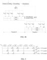
- one uplink subframe will correspond to multiple downlink subframes, and each downlink subframe has n cells, as shown in FIG. 3 .
- each cell can have one transmission block for transmission and also can have two transmission blocks for transmission.
- the UE Due to the carrier aggregation, when one subframe corresponds to multiple cells in the frequency domain, the UE is required to perform feedback of downlink channel information of the multiple cells.
- the bit capacity of the PUCCH feedback information is limited, it fails to perform simultaneous feedback of information of multiple cells of a corresponding downlink channel in one PUCCH, thus it needs to be allocated to different subframes for performing transmission, and this will cause longer feedback delay of the information, which goes against downlink dynamic scheduling of the base station and influences the system performance.
- the main object of the present invention is to provide a method for transmitting feedback information and a User Equipment (UE) according to appended independent claims, to overcome the defect that the UE cannot perform simultaneous feedback of information of multiple cells of a corresponding downlink channel in one Physical Uplink Control Channel (PUCCH) in the related art. Further improvements and embodiments are provided in the dependent claims.
- UE User Equipment
- the present invention provides a method for transmitting feedback information, which comprises:
- the step of performing time domain extension on feedback information comprises: performing encoding, scrambling and/or interleaving, and modulation on the feedback information, and then performing Discrete Fourier Transform (DFT) on data after going through the encoding, scrambling and/or interleaving and modulation, wherein, a processing order of the scrambling, interleaving and modulation is arbitrary.
- DFT Discrete Fourier Transform
- the step of performing time domain extension on feedback information within one subframe comprises: the UE concatenating all groups of encoded feedback information in order, or interleaving all groups of encoded feedback information, or interleaving all groups of encoded feedback information by block; or after respectively performing scrambling and modulation operation on each group of encoded feedback information, the UE concatenating all groups of symbols obtained after the modulation, wherein, a concatenating way is orderly concatenating or interleaving.
- the step of dividing O bits of feedback information into Y groups comprises: starting from a first bit in a sequence composed of the feedback information, performing division into Y groups in order, except the last group, there are O Y bits contained in each group, and the number of bits contained in the last group is equal to or greater than O Y bits; or performing modulo operation between the location in which each bit is located in the sequence composed of the feedback information and the Y, and classifying bits with identical modulo values under a group; or, when the feedback information is channel state information, classifying the bits representing feedback information corresponding to each cell under a group correspondingly; or, starting from the first bit in the sequence composed of the feedback information, performing division into Y groups in order, wherein the number of bits contained in each group of O mod Y groups is O Y + 1 , and the number of bits contained in each group of remaining Y -( O modY) groups is O Y .
- an interleaving way is to perform interleaving on data to be interleaved according to a fixed sequence, or to perform interleaving on the data to be interleaved according to a row-wise write and column-wise read way, or to perform interleaving according to a block interleaving method.
- the step of performing DFT on data after going through the encoding, scrambling and/or interleaving and modulation comprises: performing DFT processing on all data in the time domain, or performing DFT processing on data borne by each physical resource block in the time domain respectively.
- a sequence of the demodulation reference signals is composed of a sequence with the length of n ⁇ L ; or a sequence of the demodulation reference signals is composed of n sequences with lengths of L, wherein L is the number of subcarriers contained in one physical resource block.
- the sequence is a Zadoff-Chu (ZC) sequence or a Computer Generation ZC sequence.
- the feedback information comprises any one or any combination of ACKnowledgement or Non-ACKnowledgement (ACK/NACK) information, channel state information, rank indication information and scheduling request information.
- ACK/NACK ACKnowledgement or Non-ACKnowledgement
- the present invention further provides a method for transmitting feedback information, and the method comprises: after a user equipment dividing feedback information into n groups, transmitting each group of data correspondingly through one Physical Uplink Control Channel (PUCCH) of which a format is PUCCH Format 2 or PUCCH Format 3; wherein, n is 2, and PUCCHs bearing the data occupy a same physical resource block or adjacent physical resource blocks in the frequency domain.
- PUCCH Physical Uplink Control Channel
- the step of a user equipment dividing feedback information into n groups comprises: starting from a first bit in a sequence composed of O bits of the feedback information, performing division into n groups in order, except the last group, there are O n bits contained in each group, and the number of bits contained in the last group is equal to or greater than O n bits; or performing modulo operation between the location in which each bit is located in the sequence composed of the feedback information and the n, and classifying bits with identical modulo values under a group; or, when the feedback information is channel state information, classifying the bits representing feedback information corresponding to each cell under a group correspondingly; or, starting from the first bit in the sequence composed of the feedback information, performing division into Y groups in order, wherein the number of bits contained in each group of O mod 72 groups is O n + 1 , and the number of bits contained in each group of remaining n - ( O mod n ) groups is O n .
- the feedback information comprises any one or any combination of ACKnowledgement or Non-ACKnowledgement (ACK/NACK) information, channel state information, rank indication information and scheduling request information.
- ACK/NACK ACKnowledgement or Non-ACKnowledgement
- the present invention further provides a user equipment, and the user equipment comprises: a time domain extension module and a data transmission module;
- the time domain extension module is configured to perform time domain extension on the feedback information within one subframe in the following way: performing encoding, scrambling and/or interleaving and modulation on the feedback information, and performing Discrete Fourier Transform (DFT) on data which go through the above processing, wherein, a processing order of the scrambling, interleaving and modulation is arbitrary.
- DFT Discrete Fourier Transform
- the present invention further provides a user equipment, and the user equipment comprises: a group division module and a transmission module;
- the group division module is configured to divide the feedback information into n groups in the following way:
- the number of bits of feedback information of UE is increased, which enhances the uplink feedback capacity, guarantees the maximum throughput of the system, and decreases the feedback delay of downlink channel information.
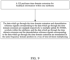
- a method for transmitting feedback information according to the example of the present invention is as shown in FIG. 9 , and the method includes: a UE performing time domain extension on feedback information within one subframe; wherein, the feedback information can be any one or any combination of ACKnowledgement or Non-ACKnowledgement (ACK/NACK) information, channel state information, rank indication information and scheduling request information; and the number of bits contained in the feedback information can be determined according to uplink-downlink timeslot configurations, cells configured for the UE and corresponding transmission modes; mapping data which go through the time domain extension and demodulation reference signals corresponding to the data which go through the time domain extension respectively to multiple uplink SC-FDMA symbols within the subframe, and transmitting the data which go through the time domain extension and the demodulation reference signals corresponding to the data which go through the time domain extension in a same frequency domain position in a way of time division multiplexing; wherein, each uplink SC-FDMA symbol occupies n successive physical resource blocks in the frequency domain, and n is a positive integer; a
- a physical resource block index occupied by an uplink SC-FDMA symbol within a first timeslot in the subframe is m
- a physical resource block index occupied by an uplink SC-FDMA symbol within a second timeslot in the subframe can be either N-1-m or m.
- the channel resource information can be configured to the above UE through upper layer signalings.
- mapping the data which go through the time domain extension and the demodulation reference signals corresponding to the data which go through the time domain extension to multiple uplink SC-FDMA symbols within the subframe means: mapping respectively the data which go through the time domain extension to fuplink SC-FDMA symbols within each timeslot in the subframe, and mapping respectively the demodulation reference signals corresponding to the data which go through the time domain extension to another g uplink SC-FDMA symbols within each timeslot in the subframe, that is, the data transmitted on two timeslots within the same subframe are identical after completing the mapping; or, mapping a part of the data which go through the time domain extension to f uplink SC-FDMA symbols within the first timeslot in the subframe, mapping another part of the data to f uplink SC-FDMA symbols within the second timeslot in the subframe, and mapping demodulation reference signals corresponding to all parts of the mapped data correspondingly to another g uplink SC-FDMA symbols within corresponding timeslots in
- performing time domain extension on the feedback information means: extending an encoded sequence to a corresponding uplink SC-FDMA symbol by using an orthogonal sequence, and the orthogonal sequence can be a Discrete Fourier Transform (DFT) sequence. Specifically, it includes: performing encoding, scrambling and/or interleaving and modulation on the data, and then performing DFT on data which go through the above processing. Wherein, the order of the scrambling, interleaving and modulation can be changed arbitrarily.
- DFT Discrete Fourier Transform
- the interleaving method is to perform interleaving on feedback information to be interleaved according to a sequence ⁇ x 0 , x 1 ..., x B -1 ⁇ , x 0 , x 1 ..., x B -1 is a positive integer sequence from 1 to B, wherein, B is an interleaved sequence length; or the interleaving method is a interleaving method according to row-wise write and column-wise read; an encoding method can be RM (32, O) encoding or convolutional encoding. When a convolutional encoding way is used, it is also required to perform encoding on Cyclic Redundancy Check (CRC) codes and the above feedback information together.
- CRC Cyclic Redundancy Check
- O bits of the feedback information turn into n ⁇ L ⁇ Q ⁇ 2 bits (applied to a situation that data transmitted on two timeslots within the same subframe are different) or L ⁇ Q ⁇ n bits (applied to a situation that data transmitted on two timeslots within the same subframe are identical), wherein, Q represents the number of bits corresponding to one modulation symbol, L is the number of subcarriers contained in one physical resource block, each uplink SC-FDMA symbol occupies n successive physical resource blocks in the frequency domain, and O represents the amount of feedback information required to be encoded, which is equivalent to the number of original bits, namely the number of bits before the encoding; Y represents the number of groups when the feedback information is encoded in group, and it is a positive integer.
- all groups of encoded data can be concatenated in order, such as b 0 0 , ... , b B ⁇ 1 0 , b 0 j , ... , b B ⁇ 1 j ; or all groups of encoded data can be interleaved, such as b 0 0 , ... , b 0 j , ... , b B ⁇ 1 0 , ... , b B ⁇ 1 j ; ; or all groups of encoded data can be interleaved by block, for example, the data in each group are respectively divided into two blocks in order, and blocks in each group are interleaved, for example, in two groups of data, if 24 bits are contained in each group, a result after the concatenating is b 0 0 , ... , b 0 j , ... , b B ⁇ 1 0 ... , b B ⁇ 1 j
- the group division method can be any one of the following three ways:
- performing DFT on the data which go through the above processing can be: performing DFT processing on all data in a time domain, or performing DFT processing on data of each physical resource block in the time domain respectively.
- the total bandwidth is N
- physical resource block indexes are numbered from 0
- a physical resource block index occupied by a channel which transmits the above feedback information with the above method on the first timeslot in one subframe is m
- a physical resource block index on the second timeslot in the subframe is N-1-m
- original O bits of the feedback information are encoded as n ⁇ L ⁇ Q ⁇ 2 bits
- QPSK Quadrature Phase Shift Keying
- the time domain length of the channel structure is one subframe, when a cyclic prefix is a normal cyclic prefix, the number of uplink SC-FDMA symbols corresponding to the data which go through the time domain extension is 5, the number of uplink SC-FDMA symbols corresponding to the demodulation reference signals is 2 and they are located on the 2nd uplink SC-FDMA symbol and the 6th uplink SC-FDMA symbol of each timeslot; and when the cyclic prefix is an extended cyclic prefix, the number of uplink SC-FDMA symbols corresponding to the data which go through the time domain extension is 5, the number of uplink SC-FDMA symbols corresponding to the demodulation reference signals is 1 and it is located on the 3rd uplink SC-FDMA symbol or the 4th uplink SC-FDMA symbol of each timeslot, and a time domain extended code is a 5-order DFT sequence, and at this point, the channel structure is a PUCCH Format 3.
- the total bandwidth is N
- physical resource block indexes are numbered from 0, a physical resource block index occupied by a channel which transmits the above feedback information with the above method on the first timeslot in one subframe is m , and a physical resource block index occupied on the second timeslot in the subframe is N-1-m, and the time domain length of the channel structure is one subframe, when a cyclic prefix is a normal cyclic prefix, the number of uplink SC-FDMA symbols corresponding to the data which go through the time domain extension is 5, the number of uplink SC-FDMA symbols corresponding to the demodulation reference signals is 2 and they are located on the 2nd uplink SC-FDMA symbol and the 6th uplink SC-FDMA symbol of each timeslot; and when the cyclic prefix is an extended cyclic prefix, the number of uplink SC-FDMA symbols corresponding to the data is 5, the number of uplink SC-FDMA symbols corresponding to the demodulation reference signals is 1 and it is located on the 3rd up
- the total bandwidth is N
- physical resource block indexes are numbered from 0, a physical resource block index occupied by a channel which transmits the above feedback information with the above method on the first timeslot in one subframe is m , and a physical resource block index occupied on the second timeslot in the subframe is N-1-m, and the time domain length of the channel structure is one subframe, and when a cyclic prefix is a normal cyclic prefix, the number of uplink SC-FDMA symbols corresponding to the data which go through the time domain extension is 5, the number of uplink SC-FDMA symbols corresponding to the demodulation reference signals is 2 and they are located on the 2nd uplink SC-FDMA symbol and the 6th uplink SC-FDMA symbol of each timeslot; and when the cyclic prefix is an extended cyclic prefix, the number of uplink SC-FDMA symbols corresponding to the data which go through the time domain extension is 5, the number of uplink SC-FDMA symbols corresponding to the demodulation reference signals is 1 and it
- the interleaving method is to perform interleaving according to a fixed sequence, or to perform interleaving according to row-wise write and column-wise reades, or to perform interleaving according to a block interleaving method.
- a user equipment of the example of the present invention includes a time domain extension module and a data transmission module; the time domain extension module is configured to: perform time domain extension on feedback information within one subframe; and the data transmission module is configured to: map extended data obtained by the time domain extension module and demodulation reference signals corresponding to the extended data respectively to multiple uplink SC-FDMA symbols within the subframe, and transmit the extended data and the demodulation reference signals corresponding to the extended data in a same frequency domain position in a way of time division multiplexing; wherein, each uplink SC-FDMA symbol occupies n successive physical resource blocks in the frequency domain, and n is a positive integer.
- the time domain extension module is configured to perform time domain extension on the feedback information within one subframe in the following way: performing encoding, scrambling and/or interleaving and modulation on the above feedback information, and then performing Discrete Fourier Transform (DFT) on data which go through the above processing, wherein, the processing sequence of the scrambling, interleaving and modulation is arbitrary.
- DFT Discrete Fourier Transform
- the present invention also provides a user equipment, the user equipment includes a group division module and a transmission module; the group division module is configured to: divide feedback information into n groups; and the transmission module is configured to: transmit each group of data correspondingly through one PUCCH of which a format is PUCCH Format 2 or PUCCH Format 3; wherein, n is 2, and PUCCHs bearing the data occupy a same physical resource block or adjacent physical resource blocks in the frequency domain.
- the group division module is configured to divide the feedback information into n groups in the following way:
- a PUCCH Format X is used to transmit feedback information
- channel structures of the PUCCH Format X are as shown in FIG. 4a and FIG. 4b , wherein RS represents demodulation reference signals, and it is described specifically as follows.
- n successive physical resource blocks are occupied in a frequency domain, and time domain extension is performed for data on one uplink SC-FDMA symbol, and the data after the time domain extension are mapped to an uplink SC-FDMA symbol in a corresponding time domain, and the demodulation reference signals and data are transmitted in a same frequency domain position in a way of time division multiplexing; the total bandwidth is N, and physical resource block indexes are numbered from 0, if a physical resource block index of the channel in the first timeslot is m, a physical resource block index in the second timeslot is N-1-m.
- a time domain length of the channel structure is one subframe, when a cyclic prefix is a normal cyclic prefix, as shown in FIG. 4a , the number of uplink SC-FDMA symbols corresponding to the data is 5, the number of uplink SC-FDMA symbols corresponding to the demodulation reference signals is 2 and they are respectively located on the 2nd uplink SC-FDMA symbol and the 6th uplink SC-FDMA symbol of each timeslot; and when the cyclic prefix is an extended cyclic prefix, as shown in FIG.
- a time domain extended code is a 5-order DFT sequence.
- a group division way of the first O 2 bits belonging to a group and the remaining bits belonging to a group can be used; or, a group division way of data in an even bit belonging to a group and data in an odd bit belonging to a group can be used.
- N represents the fundamental sequence length
- M i,h represents the value of serial number i in a fundamental sequence h
- O M j ⁇ 1 j represents a bit sequence of feedback information included in the j th group of data
- M j represents the number of bits contained in the j th group of data
- fundamental sequences are as shown in Table 5, and the fundamental sequences also can be in the form where the line replacement has been performed on the fundamental sequences of Table 5.
- the channel structures are as shown in FIG. 6a and FIG. 6b ;
- the group division is performed in a way of the first O 3 bits belonging to a group, the O 3 + 1 st bit to O 3 ⁇ 2 nd bit belonging to a group and the remainder bits belonging to a group;
- the channel in the example can be applied when the number of bits of ACK/NACK feedback information in TDD is greater than 11 in the carrier aggregation or when a UE needs to perform feedback of channel state information of r downlink cells simultaneously.
- Feedback information are transmitted on adjacent physical resource blocks or the same physical resource block by using n PUCCH Formats 3, wherein n is 2;
- Feedback information are transmitted on adjacent physical resource blocks or the same physical resource block by using n PUCCH Formats 2, wherein n is 2; the feedback information can be divided into n groups, each group of feedback information corresponds to one PUCCH Format 2, and each PUCCH Format 2 transmits the feedback information in a corresponding group.
- a group division method is classifying the first O 2 bits under a group and classifying the remainder bits under a group; or bits in the even bit are in a group and bits in the odd bit are in a group; or when the feedback information is channel state information, the feedback information corresponding to each cell is in a group.
- a PUCCH Format X is used to transmit feedback information
- the channel in the example can be applied when the amount of ACK/NACK feedback information in TDD is greater than 11 in the carrier aggregation or when a UE performs feedback of channel state information of r downlink cells.
- the number of bits of feedback information of UE is increased, which enhances the uplink feedback capacity, guarantees the maximum throughput of the system, and decreases the feedback delay of downlink channel information.
Landscapes
- Engineering & Computer Science (AREA)
- Signal Processing (AREA)
- Computer Networks & Wireless Communication (AREA)
- Quality & Reliability (AREA)
- Mobile Radio Communication Systems (AREA)
- Detection And Prevention Of Errors In Transmission (AREA)
Abstract
Description
- The present invention relates to the field of mobile radio communication, and particularly, to a method for transmitting feedback information and a user equipment.
- Radio frames in a Long Term Evolution (LTE) system include a frame structure of Frequency Division Duplex (FDD) mode and a frame structure of Time Division Duplex (TDD) mode. As shown in
FIG. 1 , in the frame structure of the FDD mode, one 10ms radio frame consists of 20 slots numbered as 0~19 and with length of 0.5ms, slots 2i and 2i+1 constitute a subframe i with length of 1ms (wherein, 0≤i≤9). As shown inFIG. 2 , in the frame structure of the TDD mode, one 10ms radio frame consists of 2 half frames with length of 5ms, 5 subframes with length of 1ms are included in one half frame, and the subframe i is defined as a combination of two slots 2i and 2i+1 with length of 0.5ms (wherein, 0≤i≤9). - In the above two frame structures, when a Normal Cyclic Prefix (Normal CP) is used, 7 symbols with length of 66.7us are contained in one slot, wherein the CP length of the first symbol is 5.21us, and the CP length of each of the rest 6 symbols is 4.69us; and when an Extended Cyclic Prefix (Extended CP) is used, 6 symbols are contained in one slot, and the CP length of each symbol is 16.67 us.
- Uplink-downlink configurations supported by each subframe are as shown in Table 1. Wherein, D represents a subframe exclusively used for the downlink transmission, U represents a subframe exclusively used for the uplink transmission, and S represents a special subframe used for 3 domains: Downlink Pilot Time Slot (DwPTS), Guard Period (GP) and Uplink Pilot Time Slot (UpPTS).
Table 1 A schematic table of uplink-downlink configurations supported by each subframe Uplink-downlink configurations Downlink-uplink switchover point period Subframe number # 0 1 2 3 4 5 6 7 8 9 0 5 ms D S U U U D S U U U 1 5 ms D S U U D D S U U D 2 5 ms D S U D D D S U D D 3 10 ms D S U U U D D D D D 4 10 ms D S U U D D D D D D 5 10 ms D S U D D D D D D D 6 5 ms D S U U U D S U U D - From the above table, it can be seen that the LTE TDD supports a 5ms uplink-downlink handover period and a 10ms uplink-downlink handover period. If a downlink-uplink switchover point period is 5ms, the special subframe will exist in two half frames; if the downlink-uplink switchover point period is 10ms, the special subframe only exists in the first half frame; the
subframe# 0 andsubframe # 5 and the DwPTS are always used for the downlink transmission; and the UpPTS and subframes following the special subframe closely are exclusively used for the uplink transmission. - The LTE uses a Single Carrier-Frequency Division Multiple Access (SC-FDMA) way in uplink, and an uplink time domain symbol is an uplink SC-FDMA symbol. Formats of a Physical Uplink Control Channel (PUCCH) are divided into 6 formats:
Format 1, Format 1a, Format 1b,Format 2, Format 2a and Format 2b, and 15 bits of original information can be transmitted at most. Each PUCCH occupies resources of 2 physical resource blocks in one subframe and occupies resources of 1 physical resource block in one slot. - In order to satisfy the requirements of International Telecommunication Union-Advanced (ITU-Advanced), a Long Term Evolution Advanced (LTE-A) system, as an advanced standard of the LTE, is required to support the wider system bandwidth (up to 100MHz) and is required to be backward compatible with the existing standard of the LTE. Based on the existing LTE system, bandwidths of the LTE system can be combined to obtain the wider bandwidth, and this technology is called as Carrier Aggregation (CA) technology. The technology can improve spectrum utilization efficiency of an International Mobile Telecommunications-Advanced (IMT-Advanced) system and relieve shortage of spectrum resources, thereby optimizing utilization of the spectrum resources. LTE system bandwidths of the carrier aggregation can be regarded as a Component Carriers (CC), and each component carrier also can be called as one Cell, and it can be formed from the aggregation of n component carriers (Cells). Resources of an R10 User Equipment (UE) are composed of n cells (component carriers) of the frequency domain, wherein, one cell is called as a Primary cell, and each of the rest cells is called as a Secondary cell.
- A format based on Discrete Fourier Transform Spread-Orthogonal Frequency Division Multiplexing (DFT-S-OFDM) is introduced in the LTE-A system, which is used to support that a UE with more than 4 bits performs feedback of ACKnowledgement/Non-ACKnowledgement (ACK/NACK) messages, and this new format based on the DFT- S-OFDM is called as a
control channel format 3, and the PUCCHFormat 3 uses an encoding way of Reed Muller (32, O) in the related art (i.e. an RM (32, O) encoding way), and 11 bits of information can be transmitted at most. - In a TDD system, one uplink subframe will correspond to multiple downlink subframes, and each downlink subframe has n cells, as shown in
FIG. 3 . According to different transmission modes, each cell can have one transmission block for transmission and also can have two transmission blocks for transmission. Due to the carrier aggregation, when one subframe corresponds to multiple cells in the frequency domain, the UE is required to perform feedback of downlink channel information of the multiple cells. Currently, since the bit capacity of the PUCCH feedback information is limited, it fails to perform simultaneous feedback of information of multiple cells of a corresponding downlink channel in one PUCCH, thus it needs to be allocated to different subframes for performing transmission, and this will cause longer feedback delay of the information, which goes against downlink dynamic scheduling of the base station and influences the system performance. - The main object of the present invention is to provide a method for transmitting feedback information and a User Equipment (UE) according to appended independent claims, to overcome the defect that the UE cannot perform simultaneous feedback of information of multiple cells of a corresponding downlink channel in one Physical Uplink Control Channel (PUCCH) in the related art. Further improvements and embodiments are provided in the dependent claims.
- In order to solve the above problem, the present invention provides a method for transmitting feedback information, which comprises:
- a User Equipment (UE) performing time domain extension on feedback information within one subframe; and
- mapping respectively data which go through the time domain extension and demodulation reference signals corresponding to the data which go through the time domain extension to multiple uplink Single Carrier-Frequency Division Multiple Access (SC-FDMA) symbols within the subframe, and transmitting the data which go through the time domain extension and the demodulation reference signals corresponding to the data which go through the time domain extension in a same frequency domain position in a way of time division multiplexing;
- wherein, each uplink SC-FDMA symbol occupies n successive physical resource blocks in the frequency domain, and n is a positive integer.
- In the above method,
the step of performing time domain extension on feedback information comprises: performing encoding, scrambling and/or interleaving, and modulation on the feedback information, and then performing Discrete Fourier Transform (DFT) on data after going through the encoding, scrambling and/or interleaving and modulation, wherein, a processing order of the scrambling, interleaving and modulation is arbitrary. - In the above method,
the step of performing encoding on the feedback information comprises: firstly dividing <9 bits of feedback information into Y groups, and then encoding each group of data respectively, an encoding way is RM (32, O) encoding or convolutional encoding; wherein, if the length of the ith group of encoded data is
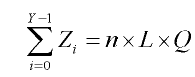
- In the above method, the step of performing time domain extension on feedback information within one subframe comprises:
the UE concatenating all groups of encoded feedback information in order, or interleaving all groups of encoded feedback information, or interleaving all groups of encoded feedback information by block; or after respectively performing scrambling and modulation operation on each group of encoded feedback information, the UE concatenating all groups of symbols obtained after the modulation, wherein, a concatenating way is orderly concatenating or interleaving. - In the above method,
the step of dividing O bits of feedback information into Y groups comprises: starting from a first bit in a sequence composed of the feedback information, performing division into Y groups in order, except the last group, there are


- In the above method,
an interleaving way is to perform interleaving on data to be interleaved according to a fixed sequence, or to perform interleaving on the data to be interleaved according to a row-wise write and column-wise read way, or to perform interleaving according to a block interleaving method. - In the above method,
the step of performing DFT on data after going through the encoding, scrambling and/or interleaving and modulation comprises: performing DFT processing on all data in the time domain, or performing DFT processing on data borne by each physical resource block in the time domain respectively. - In the above method,
a sequence of the demodulation reference signals is composed of a sequence with the length of n×L; or a sequence of the demodulation reference signals is composed of n sequences with lengths of L, wherein L is the number of subcarriers contained in one physical resource block. - In the above method,
the sequence is a Zadoff-Chu (ZC) sequence or a Computer Generation ZC sequence. - In the above method,
when a total bandwidth is N and physical resource block indexes are numbered from 0, if a physical resource block index occupied by an uplink SC-FDMA symbol within a first timeslot in the subframe is m, a physical resource block index occupied by an uplink SC-FDMA symbol within a second timeslot in the subframe is N-1-m or m. - In the above method,
when A uplink SC-FDMA symbols are contained in one timeslot, the step of mapping data which go through the time domain extension and demodulation reference signals corresponding to the data which go through the time domain extension to multiple uplink SC-FDMA symbols within the subframe comprises: mapping the data which go through the time domain extension respectively to fuplink SC-FDMA symbols within each timeslot in the subframe, and mapping the demodulation reference signals corresponding to the data which go through the time domain extension respectively to another g uplink SC-FDMA symbols within each timeslot in the subframe; or, mapping a part of the data which go through the time domain extension to f uplink SC-FDMA symbols within the first timeslot in the subframe, mapping another part of the data to f uplink SC-FDMA symbols within the second timeslot in the subframe, and mapping demodulation reference signals corresponding to all parts of mapped data correspondingly to another g uplink SC-FDMA symbols within corresponding timeslots in the subframe; wherein, h=f+g, and f is a time domain extended sequence length. - In the above method,
when the normal cyclic prefix is used in the timeslots, h=7, f=5 and g=2; and when the extended cyclic prefix is used in the timeslots, h=6, f=5 and g=1. - In the above method,
the feedback information comprises any one or any combination of ACKnowledgement or Non-ACKnowledgement (ACK/NACK) information, channel state information, rank indication information and scheduling request information. - In order to solve the above problem, the present invention further provides a method for transmitting feedback information, and the method comprises:
after a user equipment dividing feedback information into n groups, transmitting each group of data correspondingly through one Physical Uplink Control Channel (PUCCH) of which a format is PUCCHFormat 2 or PUCCHFormat 3; wherein, n is 2, and PUCCHs bearing the data occupy a same physical resource block or adjacent physical resource blocks in the frequency domain. - In the above method,
the step of a user equipment dividing feedback information into n groups comprises: starting from a first bit in a sequence composed of O bits of the feedback information, performing division into n groups in order, except the last group, there are


- In the above method,
the feedback information comprises any one or any combination of ACKnowledgement or Non-ACKnowledgement (ACK/NACK) information, channel state information, rank indication information and scheduling request information. - In order to solve the above problem, the present invention further provides a user equipment, and the user equipment comprises: a time domain extension module and a data transmission module;
- the time domain extension module is configured to: perform time domain extension on feedback information within one subframe;
- the data transmission module is configured to: map extended data obtained by the time domain extension module and demodulation reference signals corresponding to the extended data respectively to multiple uplink Single Carrier-Frequency Division Multiple Access (SC-FDMA) symbols within the subframe, and transmit the extended data and the demodulation reference signals corresponding to the extended data in a same frequency domain position in a way of time division multiplexing; wherein, each uplink SC-FDMA symbol occupies n successive physical resource blocks in the frequency domain, and n is a positive integer.
- In the above user equipment,
the time domain extension module is configured to perform time domain extension on the feedback information within one subframe in the following way: performing encoding, scrambling and/or interleaving and modulation on the feedback information, and performing Discrete Fourier Transform (DFT) on data which go through the above processing, wherein, a processing order of the scrambling, interleaving and modulation is arbitrary. - In order to solve the above problem, the present invention further provides a user equipment, and the user equipment comprises: a group division module and a transmission module;
- the group division module is configured to: divide feedback information into n groups;
- the transmission module is configured to: transmit each group of data correspondingly through one Physical Uplink Control Channel (PUCCH) of which a format is
PUCCH Format 2 orPUCCH Format 3; wherein, n is 2, and PUCCHs bearing the data occupy a same physical resource block or adjacent physical resource blocks in the frequency domain. - In the above user equipment,
the group division module is configured to divide the feedback information into n groups in the following way: - starting from a first bit in a sequence composed of O bits of the feedback information, performing division into n groups in order, except the last group, there are


- or performing modulo operation between a location in which each bit is located in a sequence composed of the feedback information and the n, and classifying bits with identical modulo values under a group;
- or, when feedback information is channel state information, classifying bits representing feedback information corresponding to each cell under a group correspondingly;
- or, starting from the first bit in the sequence composed of the feedback information, performing division into n groups in order, wherein the number of bits contained in each group of O mod 72 groups is


- In the present invention, the number of bits of feedback information of UE is increased, which enhances the uplink feedback capacity, guarantees the maximum throughput of the system, and decreases the feedback delay of downlink channel information.
-
-
FIG. 1 is a schematic diagram of frame structure in a FDD system in the related art. -
FIG. 2 is a schematic diagram of frame structure in a TDD system in the related art. -
FIG. 3 is a schematic diagram of downlink scheduling window corresponding to one uplink subframe in a carrier aggregation scenario in the related art. -
FIG. 4a andFIG. 4b are respectively schematic diagrams of channel structures of the PUCCH Format X in the situations of normal cyclic prefix and extended cyclic prefix when n=2. -
FIG. 5 is a schematic diagram of tail-biting convolutional code in the example of the present invention. -
FIG. 6a and FIG. 6B are respectively schematic diagrams of channel structures of the PUCCH Format X in the situations of normal cyclic prefix and extended cyclic prefix when n=3. -
FIG. 7a and FIG. 7b are respectively schematic diagrams of channel structures of the PUCCH Format X in the situations of normal cyclic prefix and extended cyclic prefix when n=1. -
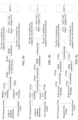
FIG. 8a, FIG. 8b and FIG. 8c are respectively schematic diagrams of encoding, modulation and mapping processes of the PUCCH Format X when n=1. -
FIG. 9 is a flow diagram of method for transmitting feedback information according to the example of the present invention. - In order to make the object, technical scheme and advantages of the present invention clear, the examples of the present invention will be described in detail in combination with the accompanying drawings below. It should be noted that the examples in the present invention and the characteristics in the examples can be optionally combined with each other in the condition of no conflict.
- A method for transmitting feedback information according to the example of the present invention is as shown in
FIG. 9 , and the method includes:
a UE performing time domain extension on feedback information within one subframe; wherein, the feedback information can be any one or any combination of ACKnowledgement or Non-ACKnowledgement (ACK/NACK) information, channel state information, rank indication information and scheduling request information; and the number of bits contained in the feedback information can be determined according to uplink-downlink timeslot configurations, cells configured for the UE and corresponding transmission modes;
mapping data which go through the time domain extension and demodulation reference signals corresponding to the data which go through the time domain extension respectively to multiple uplink SC-FDMA symbols within the subframe, and transmitting the data which go through the time domain extension and the demodulation reference signals corresponding to the data which go through the time domain extension in a same frequency domain position in a way of time division multiplexing; wherein, each uplink SC-FDMA symbol occupies n successive physical resource blocks in the frequency domain, and n is a positive integer; a sequence of the demodulation reference signals can be composed of a Computer Generation-Zadoff-Chu (CG-ZC) sequence or a ZC sequence with a length of n×L (as shown in Table 2, Table 3a and Table 3b), and it also can be composed of n CG-ZC sequences or n ZC sequences with lengths of L, wherein L is the number of subcarriers contained in one physical resource block.Table 2 30 CG-ZC sequences with lengths of 12 u ϕ(0),...,ϕ(11) 0 -1 1 3 -3 3 3 1 1 3 1 -3 3 1 1 1 3 3 3 -1 1 -3 -3 1 -3 3 2 1 1 -3 -3 -3 -1 -3 -3 1 -3 1 -1 3 -1 1 1 1 1 -1 -3 -3 1 -3 3 -1 4 -1 3 1 -1 1 -1 -3 -1 1 -1 1 3 5 1 -3 3 -1 -1 1 1 -1 -1 3 -3 1 6 -1 3 -3 -3 -3 3 1 -1 3 3 -3 1 7 -3 -1 -1 -1 1 -3 3 -1 1 -3 3 1 8 1 -3 3 1 -1 -1 -1 1 1 3 -1 1 9 1 -3 -1 3 3 -1 -3 1 1 1 1 1 10 -1 3 -1 1 1 -3 -3 -1 -3 -3 3 -1 11 3 1 -1 -1 3 3 -3 1 3 1 3 3 12 1 -3 1 1 -3 1 1 1 -3 -3 -3 1 13 3 3 -3 3 -3 1 1 3 -1 -3 3 3 14 -3 1 -1 -3 -1 3 1 3 3 3 -1 1 15 3 -1 1 -3 -1 -1 1 1 3 1 -1 -3 16 1 3 1 -1 1 3 3 3 -1 -1 3 -1 17 -3 1 1 3 -3 3 -3 -3 3 1 3 -1 18 -3 3 1 1 -3 1 -3 -3 -1 -1 1 -3 19 -1 3 1 3 1 -1 -1 3 -3 -1 -3 -1 20 -1 -3 1 1 1 1 3 1 -1 1 -3 -1 21 -1 3 -1 1 -3 -3 -3 -3 -3 1 -1 -3 22 1 1 -3 -3 -3 -3 -1 3 -3 1 -3 3 23 1 1 -1 -3 -1 -3 1 -1 1 3 -1 1 24 1 1 3 1 3 3 -1 1 -1 -3 -3 1 25 1 -3 3 3 1 3 3 1 -3 -1 -1 3 26 1 3 -3 -3 3 -3 1 -1 -1 3 -1 -3 27 -3 -1 -3 -1 -3 3 1 -1 1 3 -3 -3 28 -1 3 -3 3 -1 3 3 -3 3 3 -1 -1 29 3 -3 -3 -1 -1 -3 -1 3 -3 3 1 -1 Table 3a Values of the first 12 bits in 30 CG-ZC sequences with lengths of 24 u ϕ(0),...,ϕ(11) 0 -1 3 1 -3 3 -1 1 3 -3 3 1 3 1 -3 3 -3 -3 -3 1 -3 -3 3 -1 1 1 2 3 -1 3 3 1 1 -3 3 3 3 3 1 3 -1 -3 1 1 3 -3 1 1 -3 -1 -1 1 4 -1 -1 -1 -3 -3 -1 1 1 3 3 -1 3 5 -3 1 1 3 -1 1 3 1 -3 1 -3 1 6 1 1 -1 -1 3 -3 -3 3 -3 1 -1 -1 7 -3 3 3 -1 -1 -3 -1 3 1 3 1 3 8 -3 1 3 -3 1 -1 -3 3 -3 3 -1 -1 9 1 1 -3 3 3 -1 -3 -1 3 -3 3 3 10 -1 1 -3 -3 3 -1 3 -1 -1 -3 -3 -3 11 1 3 3 -3 -3 1 3 1 -1 -3 -3 -3 12 1 3 3 1 1 1 -1 -1 1 -3 3 -1 13 3 -1 -1 -1 -1 -3 -1 3 3 1 -1 1 14 -3 -3 3 1 3 1 -3 3 1 3 1 1 15 -1 -1 1 -3 1 3 -3 1 -1 -3 -1 3 16 -1 -3 3 -1 -1 -1 -1 1 1 -3 3 1 17 1 3 -1 3 3 -1 -3 1 -1 -3 3 3 18 1 1 1 1 1 -1 3 -1 -3 1 1 3 19 1 3 3 1 -1 -3 3 -1 3 3 3 -3 20 -1 -3 3 -3 -3 -3 -1 -1 -3 -1 -3 3 21 -3 -3 1 1 -1 1 -1 1 -1 3 1 -3 22 -3 -1 -3 3 1 -1 -3 -1 -3 -3 3 -3 23 -1 -1 -1 -1 3 3 3 1 3 3 -3 1 24 1 -1 3 3 -1 -3 3 -3 -1 -1 3 -1 25 1 -1 1 -1 3 -1 3 1 1 -1 -1 -3 26 -3 -1 1 3 1 1 -3 -1 -1 -3 3 -3 27 -1 -3 3 3 1 1 3 -1 -3 -1 -1 -1 28 -1 -3 -1 -1 1 -3 -1 -1 1 -1 -3 1 29 1 1 -1 -1 -3 -1 3 -1 3 -1 1 3 Table 3b Values of the last 12 bits in 30 CG-ZC sequences with lengths of 24 u ϕ(12),...,ϕ(23) 0 -3 3 1 1 -1 1 3 -3 3 -3 -1 -3 1 1 3 1 -1 3 -3 -3 1 3 1 1 -3 2 -1 3 -1 1 1 -1 -3 -1 -1 1 3 3 3 3 1 3 1 -1 3 1 1 -3 -1 -3 -1 4 -1 1 -1 -3 1 -1 -3 -3 1 -3 -1 -1 5 1 -1 -1 3 -1 -3 3 -3 -3 -3 1 1 6 1 -1 1 1 -1 -3 -1 1 -1 3 -1 -3 7 1 1 -1 3 1 -1 1 3 -3 -1 -1 1 8 -1 -1 1 -3 -3 -3 1 -3 -3 -3 1 -3 9 3 -1 1 1 -3 1 -1 1 1 -3 1 1 10 -1 -3 -3 1 -1 1 3 3 -1 1 -1 3 11 3 3 -3 3 3 -1 -3 3 -1 1 -3 1 12 1 1 -3 3 3 -1 -3 3 -3 -1 -3 -1 13 3 3 3 -1 1 1 -3 1 3 -1 -3 3 14 3 3 -1 -1 -3 1 -3 -1 3 1 1 3 15 1 3 1 -1 -3 -3 -1 -1 -3 -3 -3 -1 16 3 3 1 -1 1 -3 1 -3 1 1 -3 -1 17 3 -1 1 1 3 -1 -3 -1 3 -1 -1 -1 18 -3 1 -3 -1 1 1 -3 -3 3 1 1 -3 19 1 -1 1 -1 -3 -1 1 3 -1 3 -3 -3 20 1 3 -3 -1 3 -1 1 -1 3 -3 1 -1 21 -1 1 -1 1 -1 -1 3 3 -3 -1 1 -3 22 3 -3 -1 1 3 1 -3 1 3 3 -1 -3 23 3 -1 3 -1 3 3 -3 3 1 -1 3 3 24 3 -1 -1 1 1 1 1 -1 -1 -3 -1 3 25 1 1 -3 1 3 -3 1 1 -3 -3 -1 -1 26 3 1 -3 3 -3 1 -1 1 -3 1 1 1 27 3 1 -3 -3 -1 3 -3 -1 -3 -1 -3 -1 28 1 -3 1 -3 -3 3 1 1 -1 3 -1 -1 29 1 -1 3 1 3 -3 -3 1 -1 -1 1 3 - It is assumed that the total bandwidth is N and physical resource block indexes are numbered from 0, when a physical resource block index occupied by an uplink SC-FDMA symbol within a first timeslot in the subframe is m, a physical resource block index occupied by an uplink SC-FDMA symbol within a second timeslot in the subframe can be either N-1-m or m. The channel resource information can be configured to the above UE through upper layer signalings.
- When A uplink SC-FDMA symbols are contained in one timeslot, mapping the data which go through the time domain extension and the demodulation reference signals corresponding to the data which go through the time domain extension to multiple uplink SC-FDMA symbols within the subframe means: mapping respectively the data which go through the time domain extension to fuplink SC-FDMA symbols within each timeslot in the subframe, and mapping respectively the demodulation reference signals corresponding to the data which go through the time domain extension to another g uplink SC-FDMA symbols within each timeslot in the subframe, that is, the data transmitted on two timeslots within the same subframe are identical after completing the mapping; or, mapping a part of the data which go through the time domain extension to f uplink SC-FDMA symbols within the first timeslot in the subframe, mapping another part of the data to f uplink SC-FDMA symbols within the second timeslot in the subframe, and mapping demodulation reference signals corresponding to all parts of the mapped data correspondingly to another g uplink SC-FDMA symbols within corresponding timeslots in the subframe, that is, the data transmitted on two timeslots within the same subframe are different after completing the mapping. Wherein, h=f+g, and f is a time domain extended code length.
- In the specific implementation, performing time domain extension on the feedback information means: extending an encoded sequence to a corresponding uplink SC-FDMA symbol by using an orthogonal sequence, and the orthogonal sequence can be a Discrete Fourier Transform (DFT) sequence. Specifically, it includes: performing encoding, scrambling and/or interleaving and modulation on the data, and then performing DFT on data which go through the above processing. Wherein, the order of the scrambling, interleaving and modulation can be changed arbitrarily.
- Wherein, the interleaving method is to perform interleaving on feedback information to be interleaved according to a sequence { x 0, x 1 ..., x B-1 }, x 0 , x 1 ..., x B-1 is a positive integer sequence from 1 to B, wherein, B is an interleaved sequence length; or the interleaving method is a interleaving method according to row-wise write and column-wise read;
an encoding method can be RM (32, O) encoding or convolutional encoding. When a convolutional encoding way is used, it is also required to perform encoding on Cyclic Redundancy Check (CRC) codes and the above feedback information together. After going through the encoding, O bits of the feedback information turn into n×L×Q×2 bits (applied to a situation that data transmitted on two timeslots within the same subframe are different) or L ×Q ×n bits (applied to a situation that data transmitted on two timeslots within the same subframe are identical), wherein, Q represents the number of bits corresponding to one modulation symbol, L is the number of subcarriers contained in one physical resource block, each uplink SC-FDMA symbol occupies n successive physical resource blocks in the frequency domain, and O represents the amount of feedback information required to be encoded, which is equivalent to the number of original bits, namely the number of bits before the encoding; Y represents the number of groups when the feedback information is encoded in group, and it is a positive integer. - When the encoding is performed, the above O bits of the feedback information can be firstly divided into Y groups, and then each group of data is encoded respectively. It is assumed that, if the length of the ith group of data is Zi after the encoding,


- Preferably, the group division method can be any one of the following three ways:
- way 1: starting from the first bit in a sequence composed of the above feedback information, performing division into Y groups in order, except the last group, there are
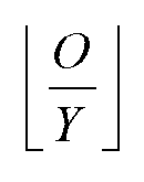

- way 2: performing modulo operation between the location in which each bit is located in the sequence composed of the above feedback information and the Y, and classifying bits with identical modulo values under a group;
- way 3: when the feedback information is channel state information, classifying bits representing feedback information corresponding to each cell under a group correspondingly;
- way 4: starting from the first bit in the sequence composed of the above feedback information, performing division into Y groups in order, wherein the number of bits contained in each group of O mod Y groups is

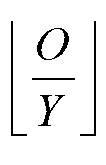
- Moreover, performing DFT on the data which go through the above processing can be: performing DFT processing on all data in a time domain, or performing DFT processing on data of each physical resource block in the time domain respectively.
- In one example, the total bandwidth is N, physical resource block indexes are numbered from 0, a physical resource block index occupied by a channel which transmits the above feedback information with the above method on the first timeslot in one subframe is m, and a physical resource block index on the second timeslot in the subframe is N-1-m, and, original O bits of the feedback information are encoded as n×L×Q×2 bits, and an RM (32, O) encoding way is used, wherein, n=1, L=12 and Q=2, and a Quadrature Phase Shift Keying (QPSK) modulation mode is used. The time domain length of the channel structure is one subframe, when a cyclic prefix is a normal cyclic prefix, the number of uplink SC-FDMA symbols corresponding to the data which go through the time domain extension is 5, the number of uplink SC-FDMA symbols corresponding to the demodulation reference signals is 2 and they are located on the 2nd uplink SC-FDMA symbol and the 6th uplink SC-FDMA symbol of each timeslot; and when the cyclic prefix is an extended cyclic prefix, the number of uplink SC-FDMA symbols corresponding to the data which go through the time domain extension is 5, the number of uplink SC-FDMA symbols corresponding to the demodulation reference signals is 1 and it is located on the 3rd uplink SC-FDMA symbol or the 4th uplink SC-FDMA symbol of each timeslot, and a time domain extended code is a 5-order DFT sequence, and at this point, the channel structure is a
PUCCH Format 3. - In another example, the total bandwidth is N, physical resource block indexes are numbered from 0, a physical resource block index occupied by a channel which transmits the above feedback information with the above method on the first timeslot in one subframe is m, and a physical resource block index occupied on the second timeslot in the subframe is N-1-m, and the time domain length of the channel structure is one subframe, when a cyclic prefix is a normal cyclic prefix, the number of uplink SC-FDMA symbols corresponding to the data which go through the time domain extension is 5, the number of uplink SC-FDMA symbols corresponding to the demodulation reference signals is 2 and they are located on the 2nd uplink SC-FDMA symbol and the 6th uplink SC-FDMA symbol of each timeslot; and when the cyclic prefix is an extended cyclic prefix, the number of uplink SC-FDMA symbols corresponding to the data is 5, the number of uplink SC-FDMA symbols corresponding to the demodulation reference signals is 1 and it is located on the 3rd uplink SC-FDMA symbol or the 4th uplink SC-FDMA symbol of each timeslot, and a time domain extended code is a 5-order DFT sequence. Original O bits of the feedback information are divided into Y groups, and RM (32, O) encoding is performed on each group of data respectively, and the length of the ith group of data is L×Q after the encoding, wherein, Y=2, L=12 and Q=2, and a QPSK modulation mode is used; or, convolutional encoding is performed on the original O bits of the feedback information, and the length is L×Q ×n×2 after encoding, wherein, Y=2, n=1, L=12 and Q=2, and the QPSK modulation mode is used; after performing encoding on the data, scrambling and/or interleaving and modulation are performed (or the scrambling and modulation are performed after performing encoding on the data, and the interleaving is performed or not performed at last), wherein, the interleaving method is to perform interleaving according to a fixed sequence, or according to a row-wise write and column-wise read interleaving method, or according to a block interleaving method.
- In another example, the total bandwidth is N, physical resource block indexes are numbered from 0, a physical resource block index occupied by a channel which transmits the above feedback information with the above method on the first timeslot in one subframe is m, and a physical resource block index occupied on the second timeslot in the subframe is N-1-m, and the time domain length of the channel structure is one subframe, and when a cyclic prefix is a normal cyclic prefix, the number of uplink SC-FDMA symbols corresponding to the data which go through the time domain extension is 5, the number of uplink SC-FDMA symbols corresponding to the demodulation reference signals is 2 and they are located on the 2nd uplink SC-FDMA symbol and the 6th uplink SC-FDMA symbol of each timeslot; and when the cyclic prefix is an extended cyclic prefix, the number of uplink SC-FDMA symbols corresponding to the data which go through the time domain extension is 5, the number of uplink SC-FDMA symbols corresponding to the demodulation reference signals is 1 and it is located on the 3rd uplink SC-FDMA symbol or the 4th uplink SC-FDMA symbol of each timeslot, and the time domain extended code is a 5-order DFT sequence. Original O bits of the feedback information are divided into Y groups, RM (32, O) encoding is performed on each group of data respectively, and the length of the ith group of data after encoding is L × Q × 2 or L × Q , wherein, Y=2, n=2, L=12 and Q=2, and the QPSK modulation mode is used; or, convolutional encoding is performed on the original O bits, and the length after encoding is L×Q ×2 ×n or L×Q ×n , wherein, Y=2, n=2, L=12 and Q=2, and the QPSK modulation mode is used. When the QPSK modulation mode is used, Q=2, when the 16 Quadrature Amplitude Modulation (QAM) modulation mode is used, Q=4, and when the 64 QAM modulation mode is used, Q=6; after performing encoding on the data, scrambling and/or interleaving and modulation are performed (or, after performing encoding on the data, the scrambling, modulation and/or interleaving are performed), wherein, the interleaving method is to perform interleaving according to a fixed sequence, or to perform interleaving according to row-wise write and column-wise reades, or to perform interleaving according to a block interleaving method.
- A user equipment of the example of the present invention includes a time domain extension module and a data transmission module; the time domain extension module is configured to: perform time domain extension on feedback information within one subframe; and the data transmission module is configured to: map extended data obtained by the time domain extension module and demodulation reference signals corresponding to the extended data respectively to multiple uplink SC-FDMA symbols within the subframe, and transmit the extended data and the demodulation reference signals corresponding to the extended data in a same frequency domain position in a way of time division multiplexing; wherein, each uplink SC-FDMA symbol occupies n successive physical resource blocks in the frequency domain, and n is a positive integer.
- In addition, the time domain extension module is configured to perform time domain extension on the feedback information within one subframe in the following way: performing encoding, scrambling and/or interleaving and modulation on the above feedback information, and then performing Discrete Fourier Transform (DFT) on data which go through the above processing, wherein, the processing sequence of the scrambling, interleaving and modulation is arbitrary.
- The present invention also provides a user equipment, the user equipment includes a group division module and a transmission module; the group division module is configured to: divide feedback information into n groups; and the transmission module is configured to: transmit each group of data correspondingly through one PUCCH of which a format is
PUCCH Format 2 orPUCCH Format 3; wherein, n is 2, and PUCCHs bearing the data occupy a same physical resource block or adjacent physical resource blocks in the frequency domain. - Wherein, the group division module is configured to divide the feedback information into n groups in the following way:
- starting from the first bit in a sequence composed of O bits of feedback information, performing division into n groups in order, except the last group, there are


- or performing modulo operation between the location in which each bit is located in a sequence composed of the feedback information and the n, and classifying bits with identical modulo values under a group;
- or, when feedback information is channel state information, classifying bits representing feedback information corresponding to each cell under a group correspondingly;
- or, starting from the first bit in the sequence composed of the feedback information, performing division into n groups in order, wherein the number of bits contained in each group of Omodn groups is

- The present invention will be further described through 4 examples below.
- A PUCCH Format X is used to transmit feedback information;
- In a carrier aggregation scenario, when n=2, channel structures of the PUCCH Format X are as shown in
FIG. 4a andFIG. 4b , wherein RS represents demodulation reference signals, and it is described specifically as follows.
n successive physical resource blocks are occupied in a frequency domain, and time domain extension is performed for data on one uplink SC-FDMA symbol, and the data after the time domain extension are mapped to an uplink SC-FDMA symbol in a corresponding time domain, and the demodulation reference signals and data are transmitted in a same frequency domain position in a way of time division multiplexing;
the total bandwidth is N, and physical resource block indexes are numbered from 0, if a physical resource block index of the channel in the first timeslot is m, a physical resource block index in the second timeslot is N-1-m. A time domain length of the channel structure is one subframe, when a cyclic prefix is a normal cyclic prefix, as shown inFIG. 4a , the number of uplink SC-FDMA symbols corresponding to the data is 5, the number of uplink SC-FDMA symbols corresponding to the demodulation reference signals is 2 and they are respectively located on the 2nd uplink SC-FDMA symbol and the 6th uplink SC-FDMA symbol of each timeslot; and when the cyclic prefix is an extended cyclic prefix, as shown inFIG. 4b , the number of uplink SC-FDMA symbols corresponding to the data is 5, the number of uplink SC-FDMA symbols corresponding to the demodulation reference signals is 1 and it is located on the 3rd uplink SC-FDMA symbol or the 4th uplink SC-FDMA symbol of each timeslot. As shown in Table 4, a time domain extended code is a 5-order DFT sequence.Table 4 DFT sequence Sequence index Sequence [w(0) ··· w(4)] 0 [1 1 1 1 1] 1 [1 e j8π/5 e j6π/5 e j4π/5 e j2π/5] 2 [1 e j6π/5 e j2π/5 e j8π/5 e j4π/5] 3 [1 e j4π/5 e j8π/5 e j2π/5 e j6π/5] 4 [1 e j2π/5 e j4π/5 e j6π/5 e j8π/5] -
Encoding scheme 1 - Original O bits of the feedback information are divided into Y groups, and RM (32, O) encoding is performed on each group of data respectively, and the length of the ith group of data after encoding is L×Q×2 or L×Q, wherein, Y=n=2, L=12 and Q=2, and a QPSK modulation mode is used; or convolutional encoding is performed on the original O bits of the feedback information, and the length is L ×Q ×2 ×n or L ×Q ×n after the encoding, wherein, Y=n=2, L=12 and Q=2, and the QPSK modulation mode is used.
- In the above encoding scheme, a group division way of the
first 
- During the specific implementation, a specific encoding way of the used RM (32, O) encoding is: the fundamental sequence length performing encoding on multiple feedback information including specifically:


Table 5 Fundamental sequences i Mi,0 Mi,1 Mi,2 Mi,3 Mi,4 Mi,5 Mi,6 Mi,7 Mi,8 Mi,9 Mi,10 0 1 1 0 0 0 0 0 0 0 0 1 1 1 1 1 0 0 0 0 0 0 1 1 2 1 0 0 1 0 0 1 0 1 1 1 3 1 0 1 1 0 0 0 0 1 0 1 4 1 1 1 1 0 0 0 1 0 0 1 5 1 1 0 0 1 0 1 1 1 0 1 6 1 0 1 0 1 0 1 0 1 1 1 7 1 0 0 1 1 0 0 1 1 0 1 8 1 1 0 1 1 0 0 1 0 1 1 9 1 0 1 1 1 0 1 0 0 1 1 10 1 0 1 0 0 1 1 1 0 1 1 11 1 1 1 0 0 1 1 0 1 0 1 12 1 0 0 1 0 1 0 1 1 1 1 13 1 1 0 1 0 1 0 1 0 1 1 14 1 0 0 0 1 1 0 1 0 0 1 15 1 1 0 0 1 1 1 1 0 1 1 16 1 1 1 0 1 1 1 0 0 1 0 17 1 0 0 1 1 1 0 0 1 0 0 18 1 1 0 1 1 1 1 1 0 0 0 19 1 0 0 0 0 1 1 0 0 0 0 20 1 0 1 0 0 0 1 0 0 0 1 21 1 1 0 1 0 0 0 0 0 1 1 22 1 0 0 0 1 0 0 1 1 0 1 23 1 1 1 0 1 0 0 0 1 1 1 24 1 1 1 1 1 0 1 1 1 1 0 25 1 1 0 0 0 1 1 1 0 0 1 26 1 0 1 1 0 1 0 0 1 1 0 27 1 1 1 1 0 1 0 1 1 1 0 28 1 0 1 0 1 1 1 0 1 0 0 29 1 0 1 1 1 1 1 1 1 0 0 30 1 1 1 1 1 1 1 1 1 1 1 31 1 0 0 0 0 0 0 0 0 0 0 - Each group of encoded bit sequences which are output after going through the encoding is b 0,b 1...,b B-1, wherein, B represents the number of bits after the encoding, if the information borne on two timeslots within the same subframe is identical, B = n×L×Q; and if the information borne on two timeslots within the same subframe is different, B=2×n×L×Q;
all groups of the bits can be concatenated in order, such as

- Feedback information O0,O 1,...O M-1 is encoded by using a tail-biting convolutional code with a constraint length of 7 and a code rate of 1/3 as shown in
FIG. 5 ; wherein, b 0,b 1 ,...,b B-1 represents a bit sequence after the encoding, B represents a length after the encoding, if the information borne on two timeslots within the same subframe is identical, B = n × L × Q , and if the information borne on two timeslots within the same subframe is different, B=2×n×L×Q;
the above interleaving process is to convert the encoded sequence b 0,b 1 ...,b B-1 to obtain
sequence 

- For example, when the number of bits to be interleaved is 48, interleaving is performed on the bits to be interleaved according to a fixed sequence { x 0, x 1..., x B-1 }, and x 0,x 1..., x B-1 is a positive integer sequence from 1 to B;
a QPSK modulation mode is used, and a modulated sequence is
- In the same structure and encoding process, when n=3, the channel structures are as shown in
FIG. 6a and FIG. 6b ; when encoding is performed on the feedback information in group, the group division is performed in a way of thefirst 


- or, bits with identical modulo values are classified under a group after bit locations modulo 3 is performed.
- or, when the feedback information is channel state information, the feedback information corresponding to each cell is in a group;
- the number of bits in O mod Y groups is


- The channel in the example can be applied when the number of bits of ACK/NACK feedback information in TDD is greater than 11 in the carrier aggregation or when a UE needs to perform feedback of channel state information of r downlink cells simultaneously.
- Feedback information are transmitted on adjacent physical resource blocks or the same physical resource block by using n PUCCH Formats 3, wherein n is 2;
- the feedback information are divided into n groups, each group of feedback information corresponds to one
PUCCH Format 3, and eachPUCCH Format 3 transmits the data in a corresponding group; - a group division method is classifying the
first 
- Channel resources of the n PUCCH Formats 3 are configured by upper layer signalings;
- the feedback information bits transmitted by the channel can be one or multiple kinds of ACK/NACK information, channel state information, rank indication information and scheduling request information.
- Feedback information are transmitted on adjacent physical resource blocks or the same physical resource block by using n PUCCH Formats 2, wherein n is 2;
the feedback information can be divided into n groups, each group of feedback information corresponds to onePUCCH Format 2, and eachPUCCH Format 2 transmits the feedback information in a corresponding group. - A group division method is classifying the
first 
- Channel resources of the n PUCCH Formats 2 can be configured by upper layer signalings;
- the feedback information bits transmitted by the channel can be one or multiple kinds of ACK/NACK information, channel state information, rank indication information and scheduling request information.
- In a carrier aggregation scenario, a PUCCH Format X is used to transmit feedback information;
- when n is 1, a channel structure is as shown in
FIG. 7 , and it is described specifically as follows. - n successive physical resource blocks are occupied in a frequency domain, and time domain extension is performed for data on one uplink SC-FDMA symbol, and the data after the time domain extension are mapped to an uplink SC-FDMA symbol in a corresponding time domain, and demodulation reference signals and data are transmitted in a same frequency domain position in a way of time division multiplexing;
- the total bandwidth is N, physical resource block indexes are numbered from 0, a physical resource block index of the channel in the first timeslot is m, a physical resource block index in the second timeslot is N-1-m, and the time domain length of the channel structure is one subframe, and when a cyclic prefix is a normal cyclic prefix, the number of uplink SC-FDMA symbols corresponding to the data is 5, the number of uplink SC-FDMA symbols corresponding to the demodulation reference signals is 2 and they are located on the 2nd uplink SC-FDMA symbol and the 6th uplink SC-FDMA symbol of each timeslot; and when the cyclic prefix is an extended cyclic prefix, the number of uplink SC-FDMA symbols corresponding to the data is 5, the number of uplink SC-FDMA symbols corresponding to the demodulation reference signals is 1 and it is located on the 3rd uplink SC-FDMA symbol or the 4th uplink SC-FDMA symbol of each timeslot, and a time domain extended code is a 5-order DFT sequence as shown in Table 4.
- Original O bits of data are divided into Y groups, RM (24, O) encoding is performed on each group of data respectively, and as shown in Table 5, the length of the ith group is L×Q after the encoding, wherein, Y=2, L=12 and Q=2, and a QPSK modulation mode is used; or the original O bits of data are divided into Y groups, convolutional encoding is performed on each group of data respectively, and the length is L×Q after the encoding, wherein, Y=2, n=1, L=12 and Q=2, and the QPSK modulation mode is used;
before the encoding, a group division way of thefirst 
- A specific encoding way of the used RM (24, O) encoding is: a fundamental sequence length performing encoding on multiple feedback information, including specifically:


- Each group of encoded bit sequences which are output after going through the encoding is b 0, b 1..., b B-1, wherein, B represents the length after the encoding, and B = 2×L×Q ;
all groups of the bits can be concatenated in order, such as



Table 6 Fundamental sequences i Mi,0 Mi,1 Mi,2 Mi,3 Mi,4 Mi,5 Mi,6 Mi,7 Mi,8 Mi,9 Mi,10 0 1 1 0 0 0 0 0 0 0 0 1 1 1 1 1 0 0 0 0 0 0 1 1 2 1 0 0 1 0 0 1 0 1 1 1 3 1 0 1 1 0 0 0 0 1 0 1 4 1 1 1 1 0 0 0 1 0 0 1 5 1 1 0 0 1 0 1 1 1 0 1 6 1 0 1 0 1 0 1 0 1 1 1 7 1 0 0 1 1 0 0 1 1 0 1 8 1 1 0 1 1 0 0 1 0 1 1 9 1 0 1 1 1 0 1 0 0 1 1 10 1 0 1 0 0 1 1 1 0 1 1 11 1 1 1 0 0 1 1 0 1 0 1 12 1 0 0 1 0 1 0 1 1 1 1 13 1 1 0 1 0 1 0 1 0 1 1 14 1 0 0 0 1 1 0 1 0 0 1 15 1 1 0 0 1 1 1 1 0 1 1 16 1 1 1 0 1 1 1 0 0 1 0 17 1 0 0 1 1 1 0 0 1 0 0 18 1 1 0 1 1 1 1 1 0 0 0 19 1 0 0 0 0 1 1 0 0 0 0 20 1 0 1 0 0 0 1 0 0 0 1 21 1 1 0 1 0 0 0 0 0 1 1 22 1 0 0 0 1 0 0 1 1 0 1 23 1 1 1 0 1 0 0 0 1 1 1 - An encoding way of tail-biting convolutional code with a constraint length of 7 and a code rate of 1/3 as shown in
FIG. 5 is used on feedback information O 0 ,O 1 ,...O M-1; b 0,b 1,...,b B-1 represents a bit sequence after the encoding, B represents the length after the encoding, and B = 2×L×Q ; - as shown in
FIG. 8a , encoding, scrambling and/or interleaving and modulation are performed on the feedback information, and then DFT is performed on data which go through the above processing; - wherein the interleaving process is to convert the encoded sequence b 0, b 1..., b B-1 to obtain


- wherein the scrambling process is that modulo-2 is performed after adding a scrambling sequence c 0 ,c 1 ,...,c B-1 and the encoded and interleaved
sequence 

- wherein the modulation mode is QPSK, and a modulated sequence is

- wherein time domain extension means extending the encoded sequence to the occupied symbols by using an orthogonal sequence, and the orthogonal sequence can be a DFT sequence;
- wherein the DFT means performing DFT operation on the modulated sequence on the symbol;
or, - as shown in
FIG. 8b , encoding, scrambling, modulation and/or interleaving are performed on the data, and then Discrete Fourier Transform (DFT) is performed on data which go through the above processing; - wherein the scrambling process is that modulo-2 is performed after adding a scrambling sequence c 0,c 1,...,c B-1 and the encoded sequence b 0,b 1,...b B-1 , and obtaining a scrambled sequence q 0 ,q 1...,q B-1, namely

- wherein the modulation mode is QPSK, (Qm = 2), and a modulated sequence is

- wherein the interleaving process is to convert the modulated
sequence 

sequence 

encoding scheme 1, each group corresponds to 12 modulation symbols, and one group is divided into 2 blocks in order, and each block contains 6 modulation symbols, interleaved concatenating is performed on all blocks, and the modulation symbol sequence is Q 0 ,Q 1, ...Q 23 before the interleaving, and the modulation symbol sequence is Q 0 ,...,Q 5 ,Q 12 ,...,Q 15 ,Q 6 ,...,Q 11,Q 16 ,...,Q 23 after the interleaving; - wherein time domain extension means extending the encoded sequence to the occupied symbols by using an orthogonal sequence, and the orthogonal sequence can be a DFT sequence;
- wherein the DFT means performing DFT operation on the modulated sequence on the symbol;
or, - as shown in
FIG. 8c , encoding, scrambling, modulation and concatenating are respectively performed on the feedback information, on which group division has been performed, in groups, and then Discrete Fourier Transform (DFT) is performed on data which go through the above processing; - wherein the scrambling process is that modulo-2 is performed after adding a scrambling sequence c 0,c 1,...,c B-1 and the encoded sequence b 0,b 1,...,b B-1, and obtaining a scrambled sequence q 0 ,q 1,...,q B-1, namely

- wherein the modulation mode is the QPSK, (Qm = 2), and a modulated sequence is

- wherein, with regard to the
encoding scheme 1, each group corresponds to 12 modulation symbols, and each group of modulation symbol sequences is
- wherein time domain extension means extending the encoded sequence to the occupied symbols by using an orthogonal sequence, and the orthogonal sequence can be a DFT sequence;
- wherein the DFT means performing DFT operation on the modulated sequence on the symbol;
- the feedback information transmitted by the channel can be one or multiple kinds of ACK/NACK information, channel state information, rank indication information and scheduling request information; according to cells configured by a UE and corresponding transmission modes, the amount of the feedback information is determined; and the channel resources are configured to a target UE through upper layer signalings.
- The channel in the example can be applied when the amount of ACK/NACK feedback information in TDD is greater than 11 in the carrier aggregation or when a UE performs feedback of channel state information of r downlink cells.
- The ordinary person skilled in the art can understand that all or part of the steps in the above method can be completed by a program instructing related hardware, and the program can be stored in a computer readable memory medium, such as a read-only memory, disk or optical disk and so on. Alternatively, all or part of the steps of the above examples also can be implemented by using one or multiple integrated circuits. Correspondingly, each module/unit in the above examples can be implemented in a form of hardware, and also can be implemented in a form of software function module. The present invention is not limited to any combination of hardware and software in a specific form.
- In the present invention, the number of bits of feedback information of UE is increased, which enhances the uplink feedback capacity, guarantees the maximum throughput of the system, and decreases the feedback delay of downlink channel information.
Claims (15)
- A method for transmitting feedback information, characterized in that the method comprising:a User Equipment, UE, performing time domain extension for feedback information within one subframe; andmapping data which go through the time domain extension and demodulation reference signals corresponding to the data which go through the time domain extension respectively to multiple uplink Single Carrier-Frequency Division Multiple Access, SC-FDMA, symbols within the subframe, and transmitting the data which go through the time domain extension and the demodulation reference signals corresponding to the data which go through the time domain extension in a same frequency domain position in a way of time division multiplexing;wherein, each uplink SC-FDMA symbol occupies n physical resource blocks in a frequency domain, n is a positive integer, and the uplink SC-FDMA symbol occupies n successive physical resource blocks in a frequency domain when the n is greater than 1;the step of performing time domain extension for feedback information comprises:firstly dividing <9 bits of feedback information into Y groups, and then encoding each group of data respectively, and Y is a positive integer greater than 1, andinterleaving all groups of encoded feedback information by block;the step of dividing <9 bits of feedback information into Y groups comprises: starting from a first bit in a sequence composed of feedback information, performing division into Y groups in order, except the last group,


- The method according to claim 1, wherein:
the step of performing time domain extension for feedback information further comprises: scrambling and modulation for the feedback information, and then performing Discrete Fourier Transform, DFT, on data which go through the encoding, scrambling, interleaving and modulation, wherein, a processing order of the scrambling, interleaving and modulation is arbitrary. - The method according to claim 1, wherein:
an encoding way being RM (32, O) encoding; wherein, if the length of the ith group of data is Zi after the encoding,

- The method according to claim 1, wherein:
an encoding way being convolutional encoding; wherein, if the length of the ith group of data is Zi after the encoding,

- The method according to claim 1, wherein, in the step of the UE interleaving all groups of encoded feedback information by block, all groups of encoded feedback information are concatenating by block, 2 bits are in a block, and all groups of encoded feedback information are interleaved with a block as a unit, or all groups of encoded feedback information are concatenated by block, 12 bits are in a group, and all groups of encoded feedback information are interleaved with a block as a unit.
- The method according to claim 5, wherein,when all groups of encoded feedback information are concatenating by block, 2 bits are in a block, and all groups of encoded feedback information are interleaved with a block as a unit, the UE interleaving all groups of encoded feedback information by block to obtain
 when all groups of encoded feedback information are concatenated by block, 12 bits are in a group, and all groups of encoded feedback information are interleaved with a block as a unit, the UE interleaving all groups of encoded feedback information by block to obtain
 wherein
- The method according to claim 2, wherein:
the step of performing DFT on data which go through the encoding, scrambling, interleaving and modulation comprises: performing DFT processing on data borne by each physical resource block in the time domain respectively. - A user equipment, the user equipment comprising: a time domain extension module and a data transmission module; characterized in that,the time domain extension module is configured to: perform time domain extension on feedback information within one subframe;the data transmission module is configured to: map extended data obtained by the time domain extension module and demodulation reference signals corresponding to the extended data respectively to multiple uplink Single Carrier-Frequency Division Multiple Access, SC-FDMA, symbols within the subframe, and transmit the extended data and the demodulation reference signals corresponding to the extended data in a same frequency domain position in a way of time division multiplexing; wherein, each uplink SC-FDMA symbol occupies n physical resource blocks in a frequency domain, n is a positive integer, and the uplink SC-FDMA symbol occupies n successive physical resource blocks in a frequency domain when the n is greater than 1,wherein the time domain extension module is configured to: perform time domain extension on the feedback information within one subframe in a following way: firstly divide O bits of feedback information into Y groups, and then encode each group of data respectively, and Y is a positive integer greater than 1; and interleave all groups of encoded feedback information by block;the time domain extension module is further configured to perform division into Y groups in order by starting from a first bit in a sequence composed of feedback information, except the last group,


- The user equipment according to claim 8, wherein:
the time domain extension module is further configured to perform time domain extension on the feedback information within one subframe in a following way: scrambling and modulation for the feedback information, and performing Discrete Fourier Transform, DFT, on data which go through the above processing, wherein, a processing order of the scrambling, interleaving and modulation is arbitrary. - The user equipment according to claim 8, wherein:
wherein an encoding way is RM (32, O) encoding; wherein, if the length of the ith group of data is Zi after the encoding,

- The user equipment according to claim 8, wherein:
wherein an encoding way is convolutional encoding; wherein, if the length of the ith group of data is Zi after the encoding,

- The user equipment according to claim 8, wherein, the time domain extension module is further configured to interleave all groups of encoded feedback information by block as follows:
all groups of encoded feedback information are concatenating by block, 2 bits are in a block, and all groups of encoded feedback information are interleaved with a block as a unit, or all groups of encoded feedback information are concatenated by block, 12 bits are in a group, and all groups of encoded feedback information are interleaved with a block as a unit. - The user equipment according to claim 12, wherein,when all groups of encoded feedback information are concatenating by block, 2 bits are in a block, and all groups of encoded feedback information are interleaved with a block as a unit, the UE interleaving all groups of encoded feedback information by block to obtain
 when all groups of encoded feedback information are concatenated by block, 12 bits are in a group, and all groups of encoded feedback information are interleaved with a block as a unit, the UE interleaving all groups of encoded feedback information by block to obtain
 wherein
- The user equipment according to claim 8, wherein:
the step of performing DFT on data which go through the encoding, scrambling, interleaving and modulation comprises: performing DFT processing on data borne by each physical resource block in the time domain respectively. - A non-transitory computer-readable storage medium storing a computer program, wherein the computer program, when executed by a processor, causes the processor to implement the method for transmitting feedback information of anyone of claims 1-7.
Applications Claiming Priority (3)
| Application Number | Priority Date | Filing Date | Title |
|---|---|---|---|
| CN201010503424.1A CN101958774B (en) | 2010-09-30 | 2010-09-30 | A kind of feedback information sending method and subscriber equipment |
| EP11827994.2A EP2608439A4 (en) | 2010-09-30 | 2011-06-30 | Method and user equipment for transmitting feedback information |
| PCT/CN2011/076678 WO2012041098A1 (en) | 2010-09-30 | 2011-06-30 | Method and user equipment for transmitting feedback information |
Related Parent Applications (1)
| Application Number | Title | Priority Date | Filing Date |
|---|---|---|---|
| EP11827994.2A Division EP2608439A4 (en) | 2010-09-30 | 2011-06-30 | Method and user equipment for transmitting feedback information |
Publications (2)
| Publication Number | Publication Date |
|---|---|
| EP4496247A2 true EP4496247A2 (en) | 2025-01-22 |
| EP4496247A3 EP4496247A3 (en) | 2025-04-30 |
Family
ID=43485899
Family Applications (2)
| Application Number | Title | Priority Date | Filing Date |
|---|---|---|---|
| EP11827994.2A Ceased EP2608439A4 (en) | 2010-09-30 | 2011-06-30 | Method and user equipment for transmitting feedback information |
| EP24218164.2A Pending EP4496247A3 (en) | 2010-09-30 | 2011-06-30 | Method and user equipment for transmitting feedback information |
Family Applications Before (1)
| Application Number | Title | Priority Date | Filing Date |
|---|---|---|---|
| EP11827994.2A Ceased EP2608439A4 (en) | 2010-09-30 | 2011-06-30 | Method and user equipment for transmitting feedback information |
Country Status (8)
| Country | Link |
|---|---|
| US (1) | US9282549B2 (en) |
| EP (2) | EP2608439A4 (en) |
| JP (1) | JP5567219B2 (en) |
| KR (1) | KR101551829B1 (en) |
| CN (1) | CN101958774B (en) |
| BR (1) | BR112013007644A2 (en) |
| RU (1) | RU2540834C2 (en) |
| WO (1) | WO2012041098A1 (en) |
Families Citing this family (34)
| Publication number | Priority date | Publication date | Assignee | Title |
|---|---|---|---|---|
| US8705644B2 (en) * | 2009-09-18 | 2014-04-22 | Electronics And Telecommunications Research Institute | Method for generating and transmitting a reference signal for uplink demodulation in a clustered DFT-spread OFDM transmission scheme |
| US8750269B2 (en) | 2009-10-23 | 2014-06-10 | Electronics And Telecommunications Research Institute | Method and apparatus for controlling transmission power in WLAN system |
| JP5073779B2 (en) * | 2010-04-30 | 2012-11-14 | 株式会社エヌ・ティ・ティ・ドコモ | Base station apparatus and user terminal |
| EP2421188A3 (en) * | 2010-08-20 | 2014-11-26 | LG Electronics Inc. | Method for transmitting control information in a wireless communication system and apparatus therefor |
| CN101958774B (en) * | 2010-09-30 | 2015-10-21 | 中兴通讯股份有限公司 | A kind of feedback information sending method and subscriber equipment |
| US9673945B2 (en) | 2011-02-18 | 2017-06-06 | Qualcomm Incorporated | Implicitly linking aperiodic channel state information (A-CSI) reports to CSI-reference signal (CSI-RS) resources |
| CN102739374B (en) * | 2011-04-12 | 2017-02-01 | 中兴通讯股份有限公司 | Feedback method of ACK/NACK under carrier aggregation, user equipment and system thereof |
| CN102377535A (en) * | 2011-09-30 | 2012-03-14 | 中兴通讯股份有限公司 | Sending method and device of uplink control information as well as terminal |
| CN103037514B (en) * | 2011-09-30 | 2017-02-22 | 上海贝尔股份有限公司 | Method and device for transmitting demodulation reference signal in communication network |
| CN103166880A (en) * | 2011-12-15 | 2013-06-19 | 中国移动通信集团公司 | Transmission method, reception method, base station and mobile relay of uplink demodulation pilot |
| JP5873708B2 (en) * | 2011-12-19 | 2016-03-01 | シャープ株式会社 | Mobile station apparatus, method and integrated circuit |
| CN103209060B (en) * | 2012-01-16 | 2016-09-21 | 普天信息技术研究院有限公司 | The resource allocation methods of a kind of physical uplink control channel and device |
| CN103384188B (en) * | 2012-05-04 | 2017-03-01 | 电信科学技术研究院 | Carrier aggregation feedback method, apparatus and system |
| WO2014153777A1 (en) * | 2013-03-29 | 2014-10-02 | Nec(China) Co., Ltd. | Methods and apparatuses for data transmission in a wireless communication system |
| WO2016019553A1 (en) | 2014-08-07 | 2016-02-11 | 华为技术有限公司 | Physical downlink data channel transmission method, base station and user equipment |
| US10171202B2 (en) * | 2014-11-11 | 2019-01-01 | Qualcomm Incorporated | Diversity repetition in mixed-rate wireless communication networks |
| EP3232672A4 (en) | 2014-12-08 | 2018-08-01 | LG Electronics Inc. | Broadcast signal transmitting device, broadcast signal receiving device, broadcast signal transmitting method, and broadcast signal receiving method |
| WO2016106683A1 (en) * | 2014-12-31 | 2016-07-07 | 华为技术有限公司 | Downlink control channel transmission method and device |
| CN104883238B (en) * | 2015-03-31 | 2018-05-01 | 重庆邮电大学 | A kind of carrier time division multiplexing modulation/demodulation methods and system |
| CN106559202B (en) * | 2015-09-29 | 2019-09-10 | 上海朗帛通信技术有限公司 | A kind of method, user equipment and base station equipment for supporting low latitude mouthful delay |
| EP3370362B1 (en) * | 2016-03-25 | 2021-07-07 | Guangdong Oppo Mobile Telecommunications Corp., Ltd. | Method and apparatus for transmitting feedback information |
| CN107231690B (en) * | 2016-03-25 | 2023-07-04 | 中兴通讯股份有限公司 | Information sending method and device |
| WO2017193350A1 (en) | 2016-05-12 | 2017-11-16 | 华为技术有限公司 | Information transmission method and user equipment |
| US10574425B2 (en) * | 2016-06-28 | 2020-02-25 | Lg Electronics Inc. | Method for receiving downlink signal and user equipment, and method for transmitting downlink signal and base station |
| WO2018113045A1 (en) * | 2016-12-19 | 2018-06-28 | 华为技术有限公司 | Method and device for uplink information transmission |
| CN108365922B (en) * | 2017-01-26 | 2021-03-30 | 华为技术有限公司 | Method, device and system for feedback |
| CN108631902B (en) * | 2017-03-24 | 2024-06-11 | 中兴通讯股份有限公司 | A configuration method and device |
| CN108633053B (en) * | 2017-03-24 | 2023-04-28 | 中兴通讯股份有限公司 | Information transmission method and device |
| WO2018199599A1 (en) * | 2017-04-24 | 2018-11-01 | 엘지전자 주식회사 | Method by which d2d terminal transmits rs for pdoa in wireless communication system, and device therefor |
| CN112511285B (en) | 2017-09-08 | 2021-11-19 | 华为技术有限公司 | Signal processing method and device based on sequence |
| CN109274473B (en) * | 2017-09-08 | 2019-10-22 | 华为技术有限公司 | Sequence-based signal processing method and device |
| CN109962763B (en) * | 2017-12-26 | 2021-09-14 | 中国移动通信有限公司研究院 | Multi-user data transmission method, device and equipment |
| CN112003677B (en) * | 2020-08-25 | 2022-03-25 | 深圳职业技术学院 | Data transmission method and system in Internet of things |
| CN115250539B (en) * | 2021-04-28 | 2025-07-01 | 大唐移动通信设备有限公司 | Access method and device |
Family Cites Families (11)
| Publication number | Priority date | Publication date | Assignee | Title |
|---|---|---|---|---|
| RU2392752C2 (en) * | 2006-01-05 | 2010-06-20 | ЭлДжи ЭЛЕКТРОНИКС ИНК. | Data transmission method and data retransmission method |
| US8369860B2 (en) * | 2006-08-18 | 2013-02-05 | Interdigital Technology Corporation | Sending and reducing uplink feedback signaling for transmission of MBMS data |
| US8503375B2 (en) * | 2007-08-13 | 2013-08-06 | Qualcomm Incorporated | Coding and multiplexing of control information in a wireless communication system |
| US8630184B2 (en) | 2007-08-15 | 2014-01-14 | Qualcomm Incorporated | Uplink control channel format |
| WO2009107985A1 (en) * | 2008-02-28 | 2009-09-03 | Lg Electronics Inc. | Method for multiplexing data and control information |
| KR101597573B1 (en) * | 2008-08-11 | 2016-02-25 | 엘지전자 주식회사 | Uplink transmission method of control information |
| US9402247B2 (en) * | 2008-10-20 | 2016-07-26 | Interdigital Patent Holdings, Inc. | Uplink control information transmission methods for carrier aggregation |
| CN101771502A (en) | 2009-01-07 | 2010-07-07 | 中兴通讯股份有限公司 | Method of information reuse, system and user end thereof |
| CN101783718A (en) | 2010-02-10 | 2010-07-21 | 中兴通讯股份有限公司 | Multiplexing method of scheduling request messages and correct and wrong answer messages |
| US8509155B2 (en) * | 2010-07-16 | 2013-08-13 | Samsung Electronics Co., Ltd. | Method and system for multiplexing acknowledgement signals and sounding reference signals |
| CN101958774B (en) * | 2010-09-30 | 2015-10-21 | 中兴通讯股份有限公司 | A kind of feedback information sending method and subscriber equipment |
-
2010
- 2010-09-30 CN CN201010503424.1A patent/CN101958774B/en active Active
-
2011
- 2011-06-30 EP EP11827994.2A patent/EP2608439A4/en not_active Ceased
- 2011-06-30 KR KR1020137008154A patent/KR101551829B1/en active Active
- 2011-06-30 WO PCT/CN2011/076678 patent/WO2012041098A1/en not_active Ceased
- 2011-06-30 BR BR112013007644A patent/BR112013007644A2/en not_active Application Discontinuation
- 2011-06-30 JP JP2013530544A patent/JP5567219B2/en active Active
- 2011-06-30 RU RU2013112503/08A patent/RU2540834C2/en active
- 2011-06-30 EP EP24218164.2A patent/EP4496247A3/en active Pending
- 2011-06-30 US US13/824,085 patent/US9282549B2/en active Active
Also Published As
| Publication number | Publication date |
|---|---|
| BR112013007644A2 (en) | 2017-09-26 |
| US9282549B2 (en) | 2016-03-08 |
| CN101958774A (en) | 2011-01-26 |
| CN101958774B (en) | 2015-10-21 |
| WO2012041098A1 (en) | 2012-04-05 |
| RU2013112503A (en) | 2014-11-10 |
| RU2540834C2 (en) | 2015-02-10 |
| JP2013543685A (en) | 2013-12-05 |
| EP4496247A3 (en) | 2025-04-30 |
| KR20130064795A (en) | 2013-06-18 |
| KR101551829B1 (en) | 2015-09-09 |
| EP2608439A1 (en) | 2013-06-26 |
| US20130182692A1 (en) | 2013-07-18 |
| EP2608439A4 (en) | 2018-02-14 |
| JP5567219B2 (en) | 2014-08-06 |
Similar Documents
| Publication | Publication Date | Title |
|---|---|---|
| EP4496247A2 (en) | Method and user equipment for transmitting feedback information | |
| EP3952178B1 (en) | Resource determining and receiving methods, electronic device, and storage medium | |
| KR101486679B1 (en) | Method and apparatus for transmitting reception confirmation in wireless system | |
| US9179458B2 (en) | Method for allocating resources for HARQ ACK/NACK signal transmission, and method and apparatus for HARQ ACK/NACK signal transmission using same | |
| US8942080B2 (en) | Transmission of bundled ACK/NAK bits | |
| US9065619B2 (en) | Method and apparatus for transmitting control information in a wireless communication system | |
| EP3010170B1 (en) | Method and user equipment for mapping ack/nack response messages | |
| EP4236610B1 (en) | Terminal device, and buffer partitioning method | |
| CN107070584B (en) | Method for transmitting control information and apparatus therefor | |
| US20180287735A1 (en) | Method and device for transmitting uplink control signal in wireless communication system | |
| US20160353388A1 (en) | Method and apparatus for transmitting control information in a wireless communication system | |
| WO2014142577A2 (en) | Method for transmitting control information and device therefor | |
| US20240187141A1 (en) | Joint coding and multiplexing of deferred sps harq-ack | |
| US9414367B2 (en) | Method and apparatus for transmitting uplink control information | |
| US10506567B2 (en) | Method and apparatus for transmitting and receiving uplink signal in wireless communication system | |
| CN106160956A (en) | Ascending control information sending method, device and subscriber equipment | |
| US20230043797A1 (en) | Apparatus and method for transmitting and receiving data and control signal in communication system | |
| US12563590B2 (en) | Apparatus and method for transmission or reception of data and control signal in communication system | |
| KR20120091960A (en) | Method and apparatus for allocating ack/nack resource and ack/nack signal transmitting method using the same |
Legal Events
| Date | Code | Title | Description |
|---|---|---|---|
| PUAI | Public reference made under article 153(3) epc to a published international application that has entered the european phase |
Free format text: ORIGINAL CODE: 0009012 |
|
| STAA | Information on the status of an ep patent application or granted ep patent |
Free format text: STATUS: REQUEST FOR EXAMINATION WAS MADE |
|
| 17P | Request for examination filed |
Effective date: 20241206 |
|
| AC | Divisional application: reference to earlier application |
Ref document number: 2608439 Country of ref document: EP Kind code of ref document: P |
|
| AK | Designated contracting states |
Kind code of ref document: A2 Designated state(s): AL AT BE BG CH CY CZ DE DK EE ES FI FR GB GR HR HU IE IS IT LI LT LU LV MC MK MT NL NO PL PT RO RS SE SI SK SM TR |
|
| REG | Reference to a national code |
Ref country code: DE Ref legal event code: R079 Free format text: PREVIOUS MAIN CLASS: H04L0001180000 Ipc: H04L0005000000 |
|
| RIC1 | Information provided on ipc code assigned before grant |
Ipc: H04L 1/00 20060101ALI20250122BHEP Ipc: H04L 1/1829 20230101ALI20250122BHEP Ipc: H04L 1/1607 20230101ALI20250122BHEP Ipc: H04L 5/00 20060101AFI20250122BHEP |
|
| PUAL | Search report despatched |
Free format text: ORIGINAL CODE: 0009013 |
|
| AK | Designated contracting states |
Kind code of ref document: A3 Designated state(s): AL AT BE BG CH CY CZ DE DK EE ES FI FR GB GR HR HU IE IS IT LI LT LU LV MC MK MT NL NO PL PT RO RS SE SI SK SM TR |
|
| RIC1 | Information provided on ipc code assigned before grant |
Ipc: H04L 1/00 20060101ALI20250325BHEP Ipc: H04L 1/1829 20230101ALI20250325BHEP Ipc: H04L 1/1607 20230101ALI20250325BHEP Ipc: H04L 5/00 20060101AFI20250325BHEP |