EP4496117A1 - Base station, and method for radiating radio waves - Google Patents
Base station, and method for radiating radio waves Download PDFInfo
- Publication number
- EP4496117A1 EP4496117A1 EP22932233.4A EP22932233A EP4496117A1 EP 4496117 A1 EP4496117 A1 EP 4496117A1 EP 22932233 A EP22932233 A EP 22932233A EP 4496117 A1 EP4496117 A1 EP 4496117A1
- Authority
- EP
- European Patent Office
- Prior art keywords
- antenna
- base station
- antenna substrate
- gasket
- case
- Prior art date
- Legal status (The legal status is an assumption and is not a legal conclusion. Google has not performed a legal analysis and makes no representation as to the accuracy of the status listed.)
- Pending
Links
Images


Classifications
-
- H—ELECTRICITY
- H01—ELECTRIC ELEMENTS
- H01Q—ANTENNAS, i.e. RADIO AERIALS
- H01Q1/00—Details of, or arrangements associated with, antennas
- H01Q1/12—Supports; Mounting means
- H01Q1/22—Supports; Mounting means by structural association with other equipment or articles
- H01Q1/24—Supports; Mounting means by structural association with other equipment or articles with receiving set
- H01Q1/241—Supports; Mounting means by structural association with other equipment or articles with receiving set used in mobile communications, e.g. GSM
- H01Q1/246—Supports; Mounting means by structural association with other equipment or articles with receiving set used in mobile communications, e.g. GSM specially adapted for base stations
-
- H—ELECTRICITY
- H01—ELECTRIC ELEMENTS
- H01Q—ANTENNAS, i.e. RADIO AERIALS
- H01Q1/00—Details of, or arrangements associated with, antennas
- H01Q1/02—Arrangements for de-icing; Arrangements for drying-out ; Arrangements for cooling; Arrangements for preventing corrosion
-
- H—ELECTRICITY
- H01—ELECTRIC ELEMENTS
- H01Q—ANTENNAS, i.e. RADIO AERIALS
- H01Q1/00—Details of, or arrangements associated with, antennas
- H01Q1/42—Housings not intimately mechanically associated with radiating elements, e.g. radome
Definitions
- the present disclosure relates to an antenna apparatus, in particular, a base station and its use.
- Patent Literatures 1 to 2 disclose a waterproofed antenna for outdoor use.
- Patent Literature 1 discloses a manhole cover with an antenna.
- Patent Literature 2 discloses an integrated antenna apparatus that is not likely to be exposed to rainwater as long as it is kept airtight.
- Patent Literature 3 discloses a millimeter wave band planar antenna.
- a gasket is sandwiched between a dielectric substrate used as an antenna radome and a ground conductor plate with integrated support plates.
- the gasket surrounds a radiation circuit on the ground conductor plate.
- An object of the present disclosure is to provide an antenna apparatus, in particular, a base station, in which consideration is given to waterproofing and cooling in view of the above-mentioned problems.
- a base station includes: an antenna substrate configured to emit radio waves; a case; and a gasket.
- the antenna substrate has an antenna formed on a front surface thereof.
- the case has a window. The antenna is exposed on the outside of the case through the window.
- the gasket surrounds the window. The front surface of the antenna substrate and an inner surface of the case pinch the gasket.
- the base station further includes a stiffener on a rear surface of the antenna substrate, the stiffener extending along the gasket.
- the radio waves are radiated from the antenna while having the surface of the antenna exposed to the outside air. Heat generated due to emission of the radio waves is released from the surface of the antenna to the outside air.
- Fig. 1 shows a cross-section of a base station 10.
- the base station 10 includes a case 11, an antenna substrate 13, and a gasket 16.
- the case 11 accommodates the antenna substrate 13 and the gasket 16.
- the case 11 further accommodates components other than the antenna substrate 13 constituting the base station 10. Illustrations of the components are omitted.
- the base station 10 has communication wiring, power wiring, or terminals for connecting the inside of the case 11 with the outside of the case 11. Illustrations of these wiring and terminals are omitted.
- Fig. 1 shows the antenna substrate 13, illustrating a front surface of the antenna substrate on the lower side of the drawing and a rear surface of the antenna substrate on the upper side of the drawing.
- the antenna substrate 13 has an antenna 12 formed on its front surface.
- the antenna 12 is a flat antenna, preferably a planar antenna.
- the front surface of the antenna substrate 13, including the antenna 12, is waterproof-treated.
- the antenna substrate 13 also has a coating 19 covering the surface of the antenna 12.
- the coating 19 serves to make the antenna 12 waterproof.
- the coating 19 is a coating film.
- Examples of the material of the coating 19 include fluoropolymer and silicone.
- the case 11 shown in Fig. 1 has a window 15.
- the window 15 is a through hole provided in the case 11.
- the antenna 12 is exposed on the outside of the case 11 through the window 15.
- the case 11 includes a box-shaped housing 17 and a cover 14 that serves as a lid for the housing 17.
- the window 15 is located in the center of the cover 14.
- the gasket 16 surrounds the window 15.
- the gasket 16 is annular in one example embodiment.
- the antenna substrate 13 and the cover 14 are fastened to each other with the gasket 16 interposed therebetween.
- the front surface of the antenna substrate 13 and the inner surface of the case 11 pinch the gasket 16.
- the gasket 16 is made of an elastomer, such as fluororubber or silicone rubber.
- the pinched gasket 16 repels and pushes back the front surface of the antenna substrate 13 and the inner surface of the case 11. Accordingly, the gap between the front surface of the antenna substrate 13 and the inner surface of the case 11 is filled.
- the gasket 16 prevents water and dust from entering the case 11 through this gap.
- the cross-sectional shape and the overall shape of the gasket 16 before being pinched are appropriately designed. At least one of the front surface of the antenna substrate 13 and the inner surface of the case 11 may have a groove for fitting the gasket 16.
- the coating 19 shown in Fig. 1 covers at least a part of the front surface of the antenna substrate 13 that is surrounded by the gasket 16.
- the gasket 16 and the coating 19 serve to make the front of the antenna substrate 13 waterproof.
- the coating 19 covers at least a part of the front surface of the antenna substrate 13 that is surrounded by the gasket 16.
- the gasket 16 is brought in contact with the coating 19.
- the base station 10 shown in Fig. 1 further includes a stiffener 18 on the rear surface of the antenna substrate 13.
- the stiffener 18 is formed separate from the antenna substrate 13.
- the stiffener 18 is integrally formed with the antenna substrate 13.
- the stiffener 18 has a rail shape or other shape.
- the stiffener 18 extends along the gasket 16.
- the stiffener 18 is annular.
- the stiffener 18 is made of an insulating material.
- the gasket 16 shown in Fig. 1 serves to make the interior of the case 11 waterproof.
- the antenna substrate 13 is deformed by the repulsion of the gasket 16. Therefore, warpage is generated to the antenna substrate 13.
- the warpage of the antenna substrate 13 impairs the waterproofing property. This is because the antenna substrate 13 cannot sufficiently crush the gasket 16.
- the stiffener 18 shown in Fig. 1 reinforces the rear surface of the antenna substrate 13 to suppress the warpage of the antenna substrate 13.
- the stiffener 18 helps the front surface of the antenna substrate 13 to crush the gasket 16 uniformly and sufficiently.
- the stiffener 18 prevents water from entering the case 11 from any point on the gasket 16.
- the deformation of the antenna substrate 13 shown in Fig. 1 may lead to a failure of the components mounted on the antenna substrate 13.
- the stiffener 18 also helps to prevent the failure of these components by suppressing the deformation of the antenna substrate 13.
- the gap between the cover 14 and the housing 17 are made waterproof.
- the case 11 is opened by separating the cover 14 and the housing 17 in one example embodiment. Maintenance of the rear surface of the antenna substrate 13 inside the case 11 can be performed by opening the case 11. In addition, maintenance of the components other than the antenna substrate 13 can be performed.
- the cover 14 and the housing 17 are joined again, the gap between the cover 14 and the housing 17 is made waterproof again. Waterproof treatment may be performed by installing the gasket between the cover 14 and the housing 17.
- the base station 10 shown in Fig. 1 is used as follows. Radio waves are emitted to the antenna 12 while having the surface of the antenna 12 exposed to the outside air. The heat generated due to emission of radio waves is released from the surface of the antenna 12 to the outside air. In a preferred example embodiment, the antenna 12 emits its own heat to the outside of the case 11 through the coating 19.
- the base station 10 shown in Fig. 1 is attached to a structure built on land. Examples of structures are buildings, columns, towers, tunnels, and basements. In other example embodiments, the base station 10 is attached to objects that travel on land, on water, or through the air. The objects that travel are manned or unmanned. Examples of objects that travel are automobiles, airships, and ships.
- the base station 10 shown in Fig. 1 is installed outdoors where it may rain or snow. In other example embodiments, the base station 10 is installed indoors where splashing or generation of water droplets can occur. In these cases, water enters the housing 17 from between the antenna substrate 13 and the cover 14. The gasket 16 prevents water from entering inside the housing 17 as described above.
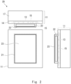
- Fig. 2 shows a three-view diagram of a base station 20, which is an example embodiment of the base station 10 shown in Fig. 1 .
- the bottom left is a front view
- the top of the front view is a plan view
- the right of the front view is a left side view.
- the base station 20 is different from the base station 10 shown in Fig. 1 in that it includes a radome 21.
- the radome 21 is fixed to the front surface of the cover 14.
- the radome 21 covers the window 15.
- the radome 21 is made of an insulating material, for example, resin.
- the radome 21 has a duct 22 and a top part 23.
- the duct 22 is provided around the top part 23, in other words, at the base part of the radome 21.
- the duct 22 is open just enough for raindrops to pass through.
- the diameter of raindrops is said to be approximately 0.2 to 6 mm.
- the radome 21 has at least one duct 22. Outside air enters through the duct 22 and the window 15 to the front surface of the antenna substrate 13.
- the antenna on the antenna substrate 13 makes direct contact with the outside air through the duct 22 of the radome 21.
- two or more ducts 22 are provided.
- the outside air in the radome 21 circulates as the outside air passes from one duct 22 toward the other duct 22.
- the top part 23 faces the front surface of the antenna substrate 13 through the window 15.
- the top part 23 protects antenna on the antenna substrate 13 from flying objects, for example.
- the radome 21 may be removed from the base station 20 if necessary.
- the base station 10 without a radome is also useful, as shown in Fig. 1 .
- the radome 21 shown in Fig. 2 may be integrally molded with the cover 14.
- the shape of the radome 21, the shape of the cover 14, and the shape of the housing 17 are variously designed to suit the performance required of a base station and the location of the base station.
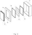
- Fig. 3 shows an exploded view of the base station 20.
- the left-hand side in the figure is the front surface side.
- the antenna substrate 13 is fixed around the window 15 from the inside of the cover 14.
- the gasket 16 is sandwiched between them.
- the antenna substrate 13 is fixed to the inside of the cover 14 by pressing the stiffener 18 against the rear surface of the antenna substrate 13.
- the stiffener 18 extends along the gasket 16.
- the antenna substrate 13 with the stiffener 18 pre-attached thereto may be pressed against the gasket 16.
- the cover 14 is attached to the housing 17 to keep the inside of the housing 17 airtight.
- the radome 21 is attached to the cover 14.
- Fig. 4 shows a cross section of a base station 30 according to a comparative example.
- the base station 30 includes a case 31 and an antenna substrate 33.
- the antenna 12 is formed on the front surface of the antenna substrate 33.
- the case 31 includes a housing 37 and a radome 34 for covering the housing 37.
- the housing 37 has a natural air cooling apparatus 32.
- the radome 34 is made of resin and includes a radio wave emission surface.
- the radome 34 protects the antenna substrate 33 and serves to make the housing 37 waterproof.
- the resin of the radome 34 includes low thermal conductivity. Therefore, the radome 34 does not release the heat generated by the antenna 12 to the outside of the case 31.
- the base station 10 shown in Fig. 1 has the antenna 12 that is exposed through the window 15. Therefore, the base station 10 shown in Fig. 1 has a cooling efficiency of the antenna higher than that of the base station 30 shown in Fig. 4 . Therefore, the base station 10 shown in Fig. 1 is advantageous in providing a smaller and lighter base station than the base station 30 shown in Fig. 4 .
- the material of the radome 34 can be changed to a material having good thermal conductivity, that is, a conductor.
- the conductor impairs radio wave emission of the antenna 12.
- the base station 10 shown in Fig. 1 does not have a radome. Therefore, the radio emission property of the antenna 12 is not impaired.
- the base station 20 shown in Fig. 2 has the radome 21 made of an insulating material. Therefore, the radome 21 does not impair the radio emission property of the antenna 12.
- the natural air cooling apparatus 32 or other heat exhausting apparatuses are essential for removing heat generated by the antenna 12.
- outside air removes the heat generated by the antenna 12 is removed by the outside air through the window 15. Therefore, it is not essential to provide a special heat exhausting apparatus in the base station 10. It can be said that the base station 10 has a simpler structure than the base station 30 shown in Fig. 4 .
- heat generated by the antenna 12 may be more efficiently removed by further attaching natural air cooling apparatus or other heat exhausting apparatus to the base station 10.
- the natural air cooling apparatus 32 removes heat generated from inside the base station 30 other than the heat generated by the antenna 12.
- heat generated from inside the base station 10 other than heat generated by the antenna 12 is removed by installing a natural air cooling apparatus or other heat exhausting apparatuses to the base station 10 shown in Fig. 1 .
- the heat exhausting apparatus required for the base station 10 shown in Fig. 1 may be smaller and have lower heat exhausting capacity than the natural air cooling apparatus 32 of the base station 30 shown in Fig. 4 . This is because in the base station 10 shown in Fig. 1 , the removal of heat generated by the antenna 12 is borne by the window 15.
- the front surface of the antenna substrate 13 is exposed to the window 15 side. Therefore, more space can be secured in the case 11. Parts and wiring arranged in the case 11 can be arranged more freely.
- a base station comprising:
- An antenna apparatus comprising:
Landscapes
- Engineering & Computer Science (AREA)
- Computer Networks & Wireless Communication (AREA)
- Details Of Aerials (AREA)
Abstract
Description
- The present disclosure relates to an antenna apparatus, in particular, a base station and its use.
- Patent Literatures 1 to 2 disclose a waterproofed antenna for outdoor use. Patent Literature 1 discloses a manhole cover with an antenna. Patent Literature 2 discloses an integrated antenna apparatus that is not likely to be exposed to rainwater as long as it is kept airtight.
- Patent Literature 3 discloses a millimeter wave band planar antenna. In the millimeter wave band planar antenna, a gasket is sandwiched between a dielectric substrate used as an antenna radome and a ground conductor plate with integrated support plates. The gasket surrounds a radiation circuit on the ground conductor plate.
-
- Patent Literature 1:
Japanese Unexamined Patent Application Publication No. 2015-012504 - Patent Literature 2: International Patent Publication No.
WO2013/125655 - Patent Literature 3:
Japanese Unexamined Patent Application Publication No. H10-190351 - In the antenna apparatus described in Patent Literatures 1 to 3, while the antenna is made waterproof or airtight, the antenna is not cooled. An object of the present disclosure is to provide an antenna apparatus, in particular, a base station, in which consideration is given to waterproofing and cooling in view of the above-mentioned problems.
- A base station includes: an antenna substrate configured to emit radio waves; a case; and a gasket. The antenna substrate has an antenna formed on a front surface thereof. The case has a window. The antenna is exposed on the outside of the case through the window. The gasket surrounds the window. The front surface of the antenna substrate and an inner surface of the case pinch the gasket. The base station further includes a stiffener on a rear surface of the antenna substrate, the stiffener extending along the gasket.
- In emitting radio waves using the base station, the radio waves are radiated from the antenna while having the surface of the antenna exposed to the outside air. Heat generated due to emission of the radio waves is released from the surface of the antenna to the outside air.
- With the present disclosure, it is possible to provide an antenna apparatus, especially a base station, in which consideration is given to waterproofing and cooling.
-
-
Fig. 1 is a cross-sectional diagram of a base station; -
Fig. 2 is a three-view diagram of a base station; -
Fig. 3 is an exploded diagram of a base station; and -
Fig. 4 is a cross-sectional diagram of a base station according to a comparative example. -
Fig. 1 shows a cross-section of abase station 10. Thebase station 10 includes acase 11, anantenna substrate 13, and agasket 16. Thecase 11 accommodates theantenna substrate 13 and thegasket 16. Thecase 11 further accommodates components other than theantenna substrate 13 constituting thebase station 10. Illustrations of the components are omitted. Thebase station 10 has communication wiring, power wiring, or terminals for connecting the inside of thecase 11 with the outside of thecase 11. Illustrations of these wiring and terminals are omitted. -
Fig. 1 shows theantenna substrate 13, illustrating a front surface of the antenna substrate on the lower side of the drawing and a rear surface of the antenna substrate on the upper side of the drawing. Theantenna substrate 13 has anantenna 12 formed on its front surface. Theantenna 12 is a flat antenna, preferably a planar antenna. The front surface of theantenna substrate 13, including theantenna 12, is waterproof-treated. - As one example embodiment of the waterproof treatment of the
antenna substrate 13 shown inFig. 1 , theantenna substrate 13 also has acoating 19 covering the surface of theantenna 12. Thecoating 19 serves to make theantenna 12 waterproof. In one example embodiment, thecoating 19 is a coating film. Examples of the material of thecoating 19 include fluoropolymer and silicone. - The
case 11 shown inFig. 1 has awindow 15. Thewindow 15 is a through hole provided in thecase 11. Theantenna 12 is exposed on the outside of thecase 11 through thewindow 15. Thecase 11 includes a box-shaped housing 17 and acover 14 that serves as a lid for thehousing 17. Thewindow 15 is located in the center of thecover 14. Thegasket 16 surrounds thewindow 15. Thegasket 16 is annular in one example embodiment. - In the
base station 10 shown inFig. 1 , theantenna substrate 13 and thecover 14 are fastened to each other with thegasket 16 interposed therebetween. The front surface of theantenna substrate 13 and the inner surface of thecase 11 pinch thegasket 16. In one example embodiment, thegasket 16 is made of an elastomer, such as fluororubber or silicone rubber. The pinchedgasket 16 repels and pushes back the front surface of theantenna substrate 13 and the inner surface of thecase 11. Accordingly, the gap between the front surface of theantenna substrate 13 and the inner surface of thecase 11 is filled. Thegasket 16 prevents water and dust from entering thecase 11 through this gap. - In the
base station 10 shown inFig. 1 , the cross-sectional shape and the overall shape of thegasket 16 before being pinched are appropriately designed. At least one of the front surface of theantenna substrate 13 and the inner surface of thecase 11 may have a groove for fitting thegasket 16. - The
coating 19 shown inFig. 1 covers at least a part of the front surface of theantenna substrate 13 that is surrounded by thegasket 16. Thegasket 16 and thecoating 19 serve to make the front of theantenna substrate 13 waterproof. In a preferred example embodiment, thecoating 19 covers at least a part of the front surface of theantenna substrate 13 that is surrounded by thegasket 16. In a preferred example embodiment, thegasket 16 is brought in contact with thecoating 19. - The
base station 10 shown inFig. 1 further includes astiffener 18 on the rear surface of theantenna substrate 13. In one example embodiment shown in the figure, thestiffener 18 is formed separate from theantenna substrate 13. In another example embodiment, thestiffener 18 is integrally formed with theantenna substrate 13. In one example embodiment, thestiffener 18 has a rail shape or other shape. Thestiffener 18 extends along thegasket 16. In one example embodiment, thestiffener 18 is annular. In one example embodiment, thestiffener 18 is made of an insulating material. - The
gasket 16 shown inFig. 1 serves to make the interior of thecase 11 waterproof. Here, theantenna substrate 13 is deformed by the repulsion of thegasket 16. Therefore, warpage is generated to theantenna substrate 13. The warpage of theantenna substrate 13 impairs the waterproofing property. This is because theantenna substrate 13 cannot sufficiently crush thegasket 16. - The
stiffener 18 shown inFig. 1 reinforces the rear surface of theantenna substrate 13 to suppress the warpage of theantenna substrate 13. Thestiffener 18 helps the front surface of theantenna substrate 13 to crush thegasket 16 uniformly and sufficiently. Thestiffener 18 prevents water from entering thecase 11 from any point on thegasket 16. - In another respect, the deformation of the
antenna substrate 13 shown inFig. 1 may lead to a failure of the components mounted on theantenna substrate 13. Thestiffener 18 also helps to prevent the failure of these components by suppressing the deformation of theantenna substrate 13. - In the
case 11 shown inFig. 1 , the gap between thecover 14 and thehousing 17 are made waterproof. Thecase 11 is opened by separating thecover 14 and thehousing 17 in one example embodiment. Maintenance of the rear surface of theantenna substrate 13 inside thecase 11 can be performed by opening thecase 11. In addition, maintenance of the components other than theantenna substrate 13 can be performed. When thecover 14 and thehousing 17 are joined again, the gap between thecover 14 and thehousing 17 is made waterproof again. Waterproof treatment may be performed by installing the gasket between thecover 14 and thehousing 17. - The
base station 10 shown inFig. 1 is used as follows. Radio waves are emitted to theantenna 12 while having the surface of theantenna 12 exposed to the outside air. The heat generated due to emission of radio waves is released from the surface of theantenna 12 to the outside air. In a preferred example embodiment, theantenna 12 emits its own heat to the outside of thecase 11 through thecoating 19. - The
base station 10 shown inFig. 1 is attached to a structure built on land. Examples of structures are buildings, columns, towers, tunnels, and basements. In other example embodiments, thebase station 10 is attached to objects that travel on land, on water, or through the air. The objects that travel are manned or unmanned. Examples of objects that travel are automobiles, airships, and ships. - The
base station 10 shown inFig. 1 is installed outdoors where it may rain or snow. In other example embodiments, thebase station 10 is installed indoors where splashing or generation of water droplets can occur. In these cases, water enters thehousing 17 from between theantenna substrate 13 and thecover 14. Thegasket 16 prevents water from entering inside thehousing 17 as described above. -
Fig. 2 shows a three-view diagram of abase station 20, which is an example embodiment of thebase station 10 shown inFig. 1 . The bottom left is a front view, the top of the front view is a plan view, and the right of the front view is a left side view. Thebase station 20 is different from thebase station 10 shown inFig. 1 in that it includes aradome 21. Theradome 21 is fixed to the front surface of thecover 14. Theradome 21 covers thewindow 15. Theradome 21 is made of an insulating material, for example, resin. Theradome 21 has aduct 22 and atop part 23. - In the
radome 21 shown inFig. 2 , theduct 22 is provided around thetop part 23, in other words, at the base part of theradome 21. Theduct 22 is open just enough for raindrops to pass through. The diameter of raindrops is said to be approximately 0.2 to 6 mm. Theradome 21 has at least oneduct 22. Outside air enters through theduct 22 and thewindow 15 to the front surface of theantenna substrate 13. The antenna on theantenna substrate 13 makes direct contact with the outside air through theduct 22 of theradome 21. Preferably, two ormore ducts 22 are provided. The outside air in theradome 21 circulates as the outside air passes from oneduct 22 toward theother duct 22. - In the
radome 21 shown inFig. 2 , thetop part 23 faces the front surface of theantenna substrate 13 through thewindow 15. Thetop part 23 protects antenna on theantenna substrate 13 from flying objects, for example. Theradome 21 may be removed from thebase station 20 if necessary. In the case where the antenna substrate does not have to be protected from the external environment, thebase station 10 without a radome is also useful, as shown inFig. 1 . - The
radome 21 shown inFig. 2 may be integrally molded with thecover 14. The shape of theradome 21, the shape of thecover 14, and the shape of thehousing 17 are variously designed to suit the performance required of a base station and the location of the base station. -
Fig. 3 shows an exploded view of thebase station 20. The left-hand side in the figure is the front surface side. Theantenna substrate 13 is fixed around thewindow 15 from the inside of thecover 14. When theantenna substrate 13 is fixed to thecover 14, thegasket 16 is sandwiched between them. Theantenna substrate 13 is fixed to the inside of thecover 14 by pressing thestiffener 18 against the rear surface of theantenna substrate 13. As explained by referring toFig. 1 , thestiffener 18 extends along thegasket 16. Theantenna substrate 13 with thestiffener 18 pre-attached thereto may be pressed against thegasket 16. Finally, thecover 14 is attached to thehousing 17 to keep the inside of thehousing 17 airtight. Further, theradome 21 is attached to thecover 14. -
Fig. 4 shows a cross section of abase station 30 according to a comparative example. Thebase station 30 includes acase 31 and anantenna substrate 33. Theantenna 12 is formed on the front surface of theantenna substrate 33. Thecase 31 includes ahousing 37 and aradome 34 for covering thehousing 37. Thehousing 37 has a naturalair cooling apparatus 32. Theradome 34 is made of resin and includes a radio wave emission surface. Theradome 34 protects theantenna substrate 33 and serves to make thehousing 37 waterproof. The resin of theradome 34 includes low thermal conductivity. Therefore, theradome 34 does not release the heat generated by theantenna 12 to the outside of thecase 31. - The
base station 10 shown inFig. 1 has theantenna 12 that is exposed through thewindow 15. Therefore, thebase station 10 shown inFig. 1 has a cooling efficiency of the antenna higher than that of thebase station 30 shown inFig. 4 . Therefore, thebase station 10 shown inFig. 1 is advantageous in providing a smaller and lighter base station than thebase station 30 shown inFig. 4 . - In the
base station 30 shown inFig. 4 , heat emitted from theradome 34 to theantenna 12 can be radiated. In this case, the material of theradome 34 can be changed to a material having good thermal conductivity, that is, a conductor. However, the conductor impairs radio wave emission of theantenna 12. In contrast, thebase station 10 shown inFig. 1 does not have a radome. Therefore, the radio emission property of theantenna 12 is not impaired. Thebase station 20 shown inFig. 2 has theradome 21 made of an insulating material. Therefore, theradome 21 does not impair the radio emission property of theantenna 12. - In the
base station 30 shown inFig. 4 , the naturalair cooling apparatus 32 or other heat exhausting apparatuses are essential for removing heat generated by theantenna 12. In contrast, in thebase station 10 shown inFig. 1 , outside air removes the heat generated by theantenna 12 is removed by the outside air through thewindow 15. Therefore, it is not essential to provide a special heat exhausting apparatus in thebase station 10. It can be said that thebase station 10 has a simpler structure than thebase station 30 shown inFig. 4 . On the other hand, heat generated by theantenna 12 may be more efficiently removed by further attaching natural air cooling apparatus or other heat exhausting apparatus to thebase station 10. - In the
base station 30 shown inFig. 4 , the naturalair cooling apparatus 32 removes heat generated from inside thebase station 30 other than the heat generated by theantenna 12. Similarly, heat generated from inside thebase station 10 other than heat generated by theantenna 12 is removed by installing a natural air cooling apparatus or other heat exhausting apparatuses to thebase station 10 shown inFig. 1 . However, the heat exhausting apparatus required for thebase station 10 shown inFig. 1 may be smaller and have lower heat exhausting capacity than the naturalair cooling apparatus 32 of thebase station 30 shown inFig. 4 . This is because in thebase station 10 shown inFig. 1 , the removal of heat generated by theantenna 12 is borne by thewindow 15. - In the
base station 10 shown inFig. 1 , the front surface of theantenna substrate 13 is exposed to thewindow 15 side. Therefore, more space can be secured in thecase 11. Parts and wiring arranged in thecase 11 can be arranged more freely. - Some or all of the above-mentioned example embodiment may be described as in the following supplementary notes, but not limited to the following.
- A base station comprising:
- an antenna substrate configured to emit radio waves;
- a case; and
- a gasket, wherein
- the antenna substrate has an antenna formed on a front surface thereof,
- the case has a window,
- the antenna is exposed on the outside of the case through the window,
- the gasket surrounds the window, and
- the front surface of the antenna substrate and the inner surface of the case pinch the gasket,
- the base station further comprising a stiffener on a rear surface of the antenna substrate, the stiffener extending along the gasket.
- The base station described in Supplementary Note 1, wherein
- the antenna substrate has a coating formed on a front surface thereof, and
- the coating serves to make the front surface of the antenna substrate, including the surface of the antenna, waterproof.
- The base station described in Supplementary Note 1 or 2, further comprising a radome made of an insulating material and covering the window, wherein
- the radome has a duct in a base part thereof, and
- a top part of the radome is opposed to the front surface of antenna substrate.
- The base station described in any one of Supplementary Notes 1 to 3, wherein the stiffener is integrally formed with the antenna substrate or is formed separate from the antenna substrate.
- The base station described in any one of Supplementary Notes 1 to 4, wherein
- the case includes a box-shaped housing and a cover that serves as a lid for the housing, and
- the cover is provided with the window.
- Use of the base station described in any one of Supplementary Notes 1 to 5, wherein the radio waves are emitted from the antenna while having the surface of the antenna exposed to the outside air, whereby heat generated due to emission of the radio waves is released from the surface of antenna to the outside air.
- An antenna apparatus comprising:
- an antenna substrate configured to emit radio waves;
- a case; and
- a gasket, wherein
- the antenna substrate has an antenna formed on a front surface thereof,
- the case is provided with a window,
- the antenna is exposed on the outside of the case through the window,
- the gasket surrounds the window, and
- the front surface of the antenna substrate and an inner surface of the case pinch the gasket,
- the base station further comprising a stiffener on a rear surface of the antenna substrate, the stiffener extending along the gasket.
- The present disclosure includes been described above with reference to the example embodiments, but the present disclosure is not limited by the foregoing.
- Various changes in the structure and details of the present disclosure can be made within the scope of the present disclosure that can be understood by a person skilled in the art.
- 10 BASE STATION, 11 CASE, 12 ANTENNA, 13 ANTENNA SUBSTRATE, 14 COVER, 15 WINDOW, 16 GASKET, 17 HOUSING, 18 STIFFENER, 19 COATING, 20 BASE STATION, 21 RADOME, 22 DUCT, 23 TOP PART, 30 BASE STATION, 31 CASE, 32 NATURAL AIR COOLING APPARATUS, 33 ANTENNA SUBSTRATE, 34 RADOME, 37 HOUSING
Claims (6)
- A base station comprising:an antenna substrate configured to emit radio waves;
a case; anda gasket, whereinthe antenna substrate has an antenna formed on a front surface thereof,the case is provided with a window,the antenna is exposed on the outside of the case through the window,the gasket surrounds the window, andthe front surface of the antenna substrate and an inner surface of the case pinch the gasket,the base station further comprising a stiffener on a rear surface of the antenna substrate, the stiffener extending along the gasket. - The base station according to claim 1, whereinthe antenna substrate has a coating formed on a front surface thereof, andthe coating serves to make the front surface of the antenna substrate, including the surface of the antenna, waterproof.
- The base station according to claim 1 or 2, further comprising a radome made of an insulating material and covering the window, whereinthe radome has a duct in a base part thereof, anda top part of the radome is opposed to the front surface of antenna substrate.
- The base station according to any one of claims 1 to 3, wherein the stiffener is integrally formed with the antenna substrate or is formed separate from the antenna substrate.
- The base station according to any one of claims 1 to 4, whereinthe case includes a box-shaped housing and a cover that serves as a lid for the housing, andthe cover is provided with the window.
- A method for emitting radio waves using the base station as claimed in any one of claims 1 to 5, comprising emitting the radio waves from the antenna while having the surface of the antenna exposed to the outside air, whereby heat generated due to emission of the radio waves is released from the surface of the antenna to the outside air.
Applications Claiming Priority (1)
| Application Number | Priority Date | Filing Date | Title |
|---|---|---|---|
| PCT/JP2022/012829 WO2023175965A1 (en) | 2022-03-18 | 2022-03-18 | Base station, and method for radiating radio waves |
Publications (2)
| Publication Number | Publication Date |
|---|---|
| EP4496117A1 true EP4496117A1 (en) | 2025-01-22 |
| EP4496117A4 EP4496117A4 (en) | 2025-04-30 |
Family
ID=88023060
Family Applications (1)
| Application Number | Title | Priority Date | Filing Date |
|---|---|---|---|
| EP22932233.4A Pending EP4496117A4 (en) | 2022-03-18 | 2022-03-18 | Base station, and method for radiating radio waves |
Country Status (4)
| Country | Link |
|---|---|
| US (1) | US20250183512A1 (en) |
| EP (1) | EP4496117A4 (en) |
| JP (1) | JP7712006B2 (en) |
| WO (1) | WO2023175965A1 (en) |
Family Cites Families (8)
| Publication number | Priority date | Publication date | Assignee | Title |
|---|---|---|---|---|
| JPH0580012U (en) * | 1992-03-30 | 1993-10-29 | 日立化成工業株式会社 | Planar antenna |
| FR2710195B1 (en) * | 1993-09-14 | 1995-10-13 | Thomson Csf | Antenna-electronic circuit assembly. |
| JPH10190351A (en) | 1996-12-25 | 1998-07-21 | Mitsubishi Electric Corp | Millimeter wave band planar antenna |
| TW512653B (en) * | 1999-11-26 | 2002-12-01 | Ibiden Co Ltd | Multilayer circuit board and semiconductor device |
| WO2013125655A1 (en) | 2012-02-21 | 2013-08-29 | 株式会社フジクラ | Antenna device |
| US9450292B2 (en) * | 2013-06-05 | 2016-09-20 | Apple Inc. | Cavity antennas with flexible printed circuits |
| JP6324673B2 (en) | 2013-06-28 | 2018-05-16 | 東京都下水道サービス株式会社 | Manhole cover with antenna |
| CN215418595U (en) * | 2021-06-21 | 2022-01-04 | 南京乾波通信技术有限公司 | Flat antenna with high space utilization rate |
-
2022
- 2022-03-18 US US18/843,770 patent/US20250183512A1/en active Pending
- 2022-03-18 EP EP22932233.4A patent/EP4496117A4/en active Pending
- 2022-03-18 WO PCT/JP2022/012829 patent/WO2023175965A1/en not_active Ceased
- 2022-03-18 JP JP2024507465A patent/JP7712006B2/en active Active
Also Published As
| Publication number | Publication date |
|---|---|
| US20250183512A1 (en) | 2025-06-05 |
| JPWO2023175965A1 (en) | 2023-09-21 |
| EP4496117A4 (en) | 2025-04-30 |
| WO2023175965A1 (en) | 2023-09-21 |
| JP7712006B2 (en) | 2025-07-23 |
Similar Documents
| Publication | Publication Date | Title |
|---|---|---|
| US10476150B2 (en) | Wireless communication device | |
| US11489249B2 (en) | Vehicular communication system | |
| JP4138862B1 (en) | Circuit board module and electronic device | |
| US7729115B2 (en) | Electrical apparatus and cooling system | |
| US10797388B2 (en) | Vehicle-mounted antenna device | |
| US10292304B2 (en) | Antenna arrangement having a fan unit | |
| EP3993155A1 (en) | Antenna device | |
| JP2019067911A (en) | Electronic equipment | |
| CN117062391A (en) | Electronic box for on-board entertainment system | |
| US20240298396A1 (en) | A lighting device | |
| AU2017405108B2 (en) | MIMO antenna module | |
| US20250183512A1 (en) | Base station and method of emitting radio waves | |
| CN117062355A (en) | Electronic box for on-board entertainment system | |
| WO2021016952A1 (en) | Communication base station | |
| KR102409410B1 (en) | Transceivers for satellites and satellites | |
| CN117498476A (en) | Wireless charging assembly | |
| JP2000223630A (en) | Heat dissipation structure for electronic components surrounded by a metal housing | |
| CN108987889B (en) | Integrated blind-mate antenna integrated with system equipment | |
| KR20220168346A (en) | Antenna module | |
| KR100918832B1 (en) | Wireless repeater | |
| CN221010135U (en) | Directional interference equipment | |
| US12435868B2 (en) | Luminaire with integrated RF communication | |
| US20250015487A1 (en) | Vehicle antenna device | |
| CN119452746A (en) | Heat dissipation device for electronic computers | |
| RU2189333C1 (en) | Helicopter |
Legal Events
| Date | Code | Title | Description |
|---|---|---|---|
| STAA | Information on the status of an ep patent application or granted ep patent |
Free format text: STATUS: THE INTERNATIONAL PUBLICATION HAS BEEN MADE |
|
| PUAI | Public reference made under article 153(3) epc to a published international application that has entered the european phase |
Free format text: ORIGINAL CODE: 0009012 |
|
| STAA | Information on the status of an ep patent application or granted ep patent |
Free format text: STATUS: REQUEST FOR EXAMINATION WAS MADE |
|
| 17P | Request for examination filed |
Effective date: 20240918 |
|
| AK | Designated contracting states |
Kind code of ref document: A1 Designated state(s): AL AT BE BG CH CY CZ DE DK EE ES FI FR GB GR HR HU IE IS IT LI LT LU LV MC MK MT NL NO PL PT RO RS SE SI SK SM TR |
|
| A4 | Supplementary search report drawn up and despatched |
Effective date: 20250331 |
|
| RIC1 | Information provided on ipc code assigned before grant |
Ipc: H01Q 1/42 20060101ALI20250325BHEP Ipc: H01Q 1/24 20060101ALI20250325BHEP Ipc: H01Q 1/02 20060101AFI20250325BHEP |
|
| DAV | Request for validation of the european patent (deleted) | ||
| DAX | Request for extension of the european patent (deleted) |