EP4496111A1 - Battery, and battery pack and vehicle comprising same - Google Patents
Battery, and battery pack and vehicle comprising same Download PDFInfo
- Publication number
- EP4496111A1 EP4496111A1 EP23843391.6A EP23843391A EP4496111A1 EP 4496111 A1 EP4496111 A1 EP 4496111A1 EP 23843391 A EP23843391 A EP 23843391A EP 4496111 A1 EP4496111 A1 EP 4496111A1
- Authority
- EP
- European Patent Office
- Prior art keywords
- electrode assembly
- diameter
- center hole
- winding center
- current collector
- Prior art date
- Legal status (The legal status is an assumption and is not a legal conclusion. Google has not performed a legal analysis and makes no representation as to the accuracy of the status listed.)
- Pending
Links
Images


Classifications
-
- H—ELECTRICITY
- H01—ELECTRIC ELEMENTS
- H01M—PROCESSES OR MEANS, e.g. BATTERIES, FOR THE DIRECT CONVERSION OF CHEMICAL ENERGY INTO ELECTRICAL ENERGY
- H01M10/00—Secondary cells; Manufacture thereof
- H01M10/04—Construction or manufacture in general
- H01M10/0431—Cells with wound or folded electrodes
-
- H—ELECTRICITY
- H01—ELECTRIC ELEMENTS
- H01M—PROCESSES OR MEANS, e.g. BATTERIES, FOR THE DIRECT CONVERSION OF CHEMICAL ENERGY INTO ELECTRICAL ENERGY
- H01M50/00—Constructional details or processes of manufacture of the non-active parts of electrochemical cells other than fuel cells, e.g. hybrid cells
- H01M50/10—Primary casings; Jackets or wrappings
- H01M50/147—Lids or covers
- H01M50/148—Lids or covers characterised by their shape
- H01M50/152—Lids or covers characterised by their shape for cells having curved cross-section, e.g. round or elliptic
-
- H—ELECTRICITY
- H01—ELECTRIC ELEMENTS
- H01M—PROCESSES OR MEANS, e.g. BATTERIES, FOR THE DIRECT CONVERSION OF CHEMICAL ENERGY INTO ELECTRICAL ENERGY
- H01M50/00—Constructional details or processes of manufacture of the non-active parts of electrochemical cells other than fuel cells, e.g. hybrid cells
- H01M50/20—Mountings; Secondary casings or frames; Racks, modules or packs; Suspension devices; Shock absorbers; Transport or carrying devices; Holders
- H01M50/204—Racks, modules or packs for multiple batteries or multiple cells
- H01M50/207—Racks, modules or packs for multiple batteries or multiple cells characterised by their shape
- H01M50/213—Racks, modules or packs for multiple batteries or multiple cells characterised by their shape adapted for cells having curved cross-section, e.g. round or elliptic
-
- H—ELECTRICITY
- H01—ELECTRIC ELEMENTS
- H01M—PROCESSES OR MEANS, e.g. BATTERIES, FOR THE DIRECT CONVERSION OF CHEMICAL ENERGY INTO ELECTRICAL ENERGY
- H01M50/00—Constructional details or processes of manufacture of the non-active parts of electrochemical cells other than fuel cells, e.g. hybrid cells
- H01M50/20—Mountings; Secondary casings or frames; Racks, modules or packs; Suspension devices; Shock absorbers; Transport or carrying devices; Holders
- H01M50/249—Mountings; Secondary casings or frames; Racks, modules or packs; Suspension devices; Shock absorbers; Transport or carrying devices; Holders specially adapted for aircraft or vehicles, e.g. cars or trains
-
- H—ELECTRICITY
- H01—ELECTRIC ELEMENTS
- H01M—PROCESSES OR MEANS, e.g. BATTERIES, FOR THE DIRECT CONVERSION OF CHEMICAL ENERGY INTO ELECTRICAL ENERGY
- H01M50/00—Constructional details or processes of manufacture of the non-active parts of electrochemical cells other than fuel cells, e.g. hybrid cells
- H01M50/30—Arrangements for facilitating escape of gases
- H01M50/342—Non-re-sealable arrangements
- H01M50/3425—Non-re-sealable arrangements in the form of rupturable membranes or weakened parts, e.g. pierced with the aid of a sharp member
-
- H—ELECTRICITY
- H01—ELECTRIC ELEMENTS
- H01M—PROCESSES OR MEANS, e.g. BATTERIES, FOR THE DIRECT CONVERSION OF CHEMICAL ENERGY INTO ELECTRICAL ENERGY
- H01M50/00—Constructional details or processes of manufacture of the non-active parts of electrochemical cells other than fuel cells, e.g. hybrid cells
- H01M50/50—Current conducting connections for cells or batteries
- H01M50/531—Electrode connections inside a battery casing
- H01M50/538—Connection of several leads or tabs of wound or folded electrode stacks
-
- H—ELECTRICITY
- H01—ELECTRIC ELEMENTS
- H01M—PROCESSES OR MEANS, e.g. BATTERIES, FOR THE DIRECT CONVERSION OF CHEMICAL ENERGY INTO ELECTRICAL ENERGY
- H01M10/00—Secondary cells; Manufacture thereof
- H01M10/05—Accumulators with non-aqueous electrolyte
- H01M10/058—Construction or manufacture
- H01M10/0587—Construction or manufacture of accumulators having only wound construction elements, i.e. wound positive electrodes, wound negative electrodes and wound separators
-
- H—ELECTRICITY
- H01—ELECTRIC ELEMENTS
- H01M—PROCESSES OR MEANS, e.g. BATTERIES, FOR THE DIRECT CONVERSION OF CHEMICAL ENERGY INTO ELECTRICAL ENERGY
- H01M2220/00—Batteries for particular applications
- H01M2220/20—Batteries in motive systems, e.g. vehicle, ship, plane
-
- Y—GENERAL TAGGING OF NEW TECHNOLOGICAL DEVELOPMENTS; GENERAL TAGGING OF CROSS-SECTIONAL TECHNOLOGIES SPANNING OVER SEVERAL SECTIONS OF THE IPC; TECHNICAL SUBJECTS COVERED BY FORMER USPC CROSS-REFERENCE ART COLLECTIONS [XRACs] AND DIGESTS
- Y02—TECHNOLOGIES OR APPLICATIONS FOR MITIGATION OR ADAPTATION AGAINST CLIMATE CHANGE
- Y02E—REDUCTION OF GREENHOUSE GAS [GHG] EMISSIONS, RELATED TO ENERGY GENERATION, TRANSMISSION OR DISTRIBUTION
- Y02E60/00—Enabling technologies; Technologies with a potential or indirect contribution to GHG emissions mitigation
- Y02E60/10—Energy storage using batteries
-
- Y—GENERAL TAGGING OF NEW TECHNOLOGICAL DEVELOPMENTS; GENERAL TAGGING OF CROSS-SECTIONAL TECHNOLOGIES SPANNING OVER SEVERAL SECTIONS OF THE IPC; TECHNICAL SUBJECTS COVERED BY FORMER USPC CROSS-REFERENCE ART COLLECTIONS [XRACs] AND DIGESTS
- Y02—TECHNOLOGIES OR APPLICATIONS FOR MITIGATION OR ADAPTATION AGAINST CLIMATE CHANGE
- Y02P—CLIMATE CHANGE MITIGATION TECHNOLOGIES IN THE PRODUCTION OR PROCESSING OF GOODS
- Y02P70/00—Climate change mitigation technologies in the production process for final industrial or consumer products
- Y02P70/50—Manufacturing or production processes characterised by the final manufactured product
Definitions
- the present disclosure relates to a battery, and a battery pack and a vehicle comprising the same.
- secondary batteries are designed to reduce the internal pressure through gas venting when the internal pressure rises due to defects or failures.
- proper venting may prevent accidents such as explosion caused by continuous rise in internal pressure.
- a portion of the electrode assembly may be ejected from a housing after venting.
- the electrode assembly may be ejected from the housing too quickly, and as a consequence, internal shorts may occur in secondary batteries, or external shorts may occur due to the ejected electrode assembly and/or broken pieces of any other metal component.
- the present disclosure is designed to address the above-described problem, and therefore the present disclosure is directed to preventing or delaying structural destruction of an electrode assembly when rises in internal pressure and/or thermal events occur due to defects or failures in a battery.
- the winding center hole may be located on an inner side of the current collector hole.
- a value obtained by dividing a difference between the diameter of the current collector hole and the diameter of the winding center hole by the diameter of the winding center hole may be equal to or larger than 0.015 and smaller than 0.4.
- a difference between the diameter of the current collector hole and the diameter of the winding center hole may be equal to or larger than 0.1 and smaller than 2.0.
- the current collector may be electrically connected to the housing.
- the cap may have a vent that is more vulnerable than a surrounding area to rupture when an internal pressure rises.
- a battery pack according to an embodiment of the present disclosure includes the battery according to an embodiment of the present disclosure.
- a vehicle according to an embodiment of the present disclosure includes the battery pack according to an embodiment of the present disclosure.
- the battery 1 may be a cylindrical battery.
- the battery 1 may include an electrode assembly 10, a housing 20 and a current collector (a first current collector) 30.
- the electrode assembly 10 may have a winding center hole 10a formed by winding a stack including a first electrode, a second electrode and a separator interposed between the first electrode and the second electrode.
- the first electrode may have a first uncoated portion 11 along a winding direction at an end portion. In this case, the first uncoated portion 11 may be disposed on a surface of the electrode assembly 10.
- the housing 20 may accommodate the electrode assembly 10 through an open portion on a side. Although not shown in FIG. 1 , the housing 20 may have a closed portion opposite the open portion.
- the housing 20 may include a conductive metal. Although FIG. 1 shows that the housing 20 is open on one side, the open portion may be closed by a separate component.
- the current collector 30 may be disposed on a surface of the electrode assembly 10 on the side of the open portion of the housing 20.
- the current collector 30 may be, for example, electrically coupled to the first uncoated portion 11 of the electrode assembly 10.
- the first uncoated portion 11 may be formed at an end portion of the first electrode of the electrode assembly 10.
- the first uncoated portion 11 may extend along the winding direction of the electrode assembly 10.
- the first uncoated portion 11 may be disposed on a surface of the electrode assembly 10, and for example, may extend in the upward direction of the electrode assembly 10.
- the current collector 30 may be configured to electrically connect the first electrode of the electrode assembly 10 to the housing 20.
- the winding center hole 10a of the electrode assembly 10 may be located on the inner side of the current collector hole 30a. That is, the current collector 30 may be disposed so as not to cover even a portion of the winding center hole 10a of the electrode assembly 10.
- the current collector 30 covers even a portion of the winding center hole 10a of the electrode assembly 10, it may result in poor flow circulation of the electrolyte solution in the process of injecting the electrolyte solution. In another aspect, in the case where the current collector 30 covers even a portion of the winding center hole 10a of the electrode assembly 10, it may result in a poor welding process through the winding center hole 10a and/or damage to the inner wall of the winding center hole 10a in the welding process.
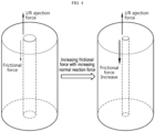
- FIG. 3 is a diagram showing the increasing normal reaction force with decreasing diameter of the winding center hole of the electrode assembly
- FIG. 4 is a diagram showing the increasing frictional force with increasing normal reaction force at the core of the electrode assembly.
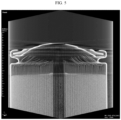
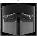
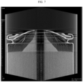
- FIGS. 5 to 7 are computed tomography (CT) images showing a change in ejection amount of the electrode assembly as a function of the diameter of the winding center hole of the electrode assembly.
- the diameter R1 of the winding center hole 10a may be equal to or larger than approximately 5.0 mm and smaller than 7.0 mm.
- the diameter R1 of the winding center hole 10a may be equal to or larger than approximately 5.0 mm and smaller than approximately 6.5 mm.
- the diameter R1 of the winding center hole 10a may be equal to or larger than approximately 6.0 mm and smaller than 6.5 mm.
- the difference (R2-R1) between the diameter R2 of the current collector hole 30a and the diameter R1 of the winding center hole 10a may be approximately 0.1 mm to 2.5 mm.
- the difference (R2-R1) between the diameter R2 of the current collector hole 30a and the diameter R1 of the winding center hole 10a may be equal to or larger than approximately 0.1 mm and smaller than 2.0 mm.
- the difference (R2-R1) between the diameter R2 of the current collector hole 30a and the diameter R1 of the winding center hole 10a may be equal to or larger than approximately 0.5 mm and smaller than 1.5 mm.
- the resistive force to the ejection force at the core of the electrode assembly 10 increases due to the increasing normal reaction force with the decreasing diameter R1 of the winding center hole 10a. This is because the frictional force between each adjacent layer of the stack including the first electrode, the second electrode and the separator increases with the increasing normal reaction force applied outwards from the core of the electrode assembly 10.
- the frictional force between each layer of the stack may act as the resistive force to the ejection force of the core of the electrode assembly 10 caused by the rise in internal pressure of the battery 1. Accordingly, when the frictional force increases, it may be possible to suppress the core ejection of the electrode assembly 10.
- the diameter R1 of the winding center hole 10a is approximately 6 mm.
- the diameter R1 of the winding center hole 10a is approximately 7 mm.
- the diameter R1 of the winding center hole 10a is approximately 8 mm.
- core ejection of the electrode assembly 10 occurs due to thermal events in the battery 1, but the ejected portion is not exposed to the outside of the battery 1.
- the core ejection length of the electrode assembly 10 is very short.
- the core ejection length of the electrode assembly 10 is very long and the electrode assembly 10 was ejected up to a location far away from the core of the electrode assembly 10.
- a value obtained by dividing the diameter R1 of the winding center hole 10a by the diameter of the electrode assembly 10 may be approximately 0.109 to 0.159.
- the value obtained by dividing the diameter R1 of the winding center hole 10a by the diameter of the electrode assembly 10 may be approximately 0.109 to 0.147.
- the value obtained by dividing the diameter R1 of the winding center hole 10a by the diameter of the electrode assembly 10 may be approximately 0.130 to 0.147.
- a value obtained by dividing the difference between the diameter R2 of the current collector hole 30a and the diameter R1 of the winding center hole 10a by the diameter of the electrode assembly 10 may be approximately 0.002 to 0.056.
- the value obtained by dividing the difference between the diameter R2 of the current collector hole 30a and the diameter R1 of the winding center hole 10a by the diameter of the electrode assembly 10 may be approximately 0.002 to 0.045.
- the value obtained by dividing the difference between the diameter R2 of the current collector hole 30a and the diameter R1 of the winding center hole 10a by the diameter of the electrode assembly 10 may be approximately 0.011 to 0.034.
- the resistive force for the suppression of core ejection of the electrode assembly 10 may be affected by a ratio of the diameter R1 of the winding center hole 10a to the total diameter of the electrode assembly 10.
- the diameter of the electrode assembly 10 of the present disclosure may be, for example, approximately 44 mm to 46 mm.
- the diameter R1 of the winding center hole 10a is too small, it may result in poor circulation of the electrolyte solution through the winding center hole 10a and/or it may be difficult to perform the process of welding the components on the opposite side to the open portion of the housing 20 through the winding center hole 10a.
- the welding is performed by laser irradiation through the winding center hole 10a, a sufficient space may be needed for stable incidence of the laser within the winding center hole 10a. Accordingly, in view of this, it is necessary to set the lower limit of the diameter R1 of the winding center hole 10a.
- the diameter R2 of the current collector hole 30a of the current collector 30 may also affect the determination of the resistive force for the suppression of core ejection of the electrode assembly 10.
- FIG. 8 is a diagram showing an upper portion structure of the battery according to an embodiment of the present disclosure.
- FIG. 9 is a top view showing the vent in the cap of the present disclosure.
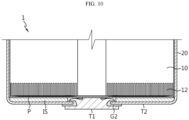
- FIG. 10 is a diagram showing a lower portion structure of the battery according to an embodiment of the present disclosure.
- the current collector 30 may be electrically connected to the housing 20.
- the current collector 30 may be, for example, electrically coupled to a beading portion extending inwards from the outer circumferential surface of the housing 20.
- the battery 1 may include a cap 40 to cover the open portion on a side of the housing 20.
- the cap 40 may be electrically insulated from the electrode assembly 10 and the housing 20, and may not be polar.
- a first insulation member G1 may be interposed between the cap 40 and the housing 20.
- the cap 40 may have a vent 40a configured to rupture when the internal pressure of the battery 1 increases.
- the vent 40a may be more vulnerable than the surrounding area.
- the vent 40a may be an area having a smaller thickness than the remaining area of the cap 40.
- the vent 40a may extend, forming a closed loop in the cap 40 as shown in FIG. 8 .
- the battery 1 of the present disclosure includes the cap 40 and the cap 40 has the vent 40a, it is more important to suppress the core ejection of the electrode assembly 10 as described above.
- core ejection is not suppressed, before gas is vented by the rupture of the vent 40a of the cap 40, a space between the cap 40 and the current collector 30 may be filled by the ejected core of the electrode assembly 10. In this case, even though the vent 40a ruptures, adequate gas venting may fail, resulting in thermal event spread.
- the battery 1 may include a first terminal T1.
- the first terminal T1 may be electrically coupled to a second uncoated portion 12 of the electrode assembly 10.
- the second uncoated portion 12 may be formed at an end portion of the second electrode.
- the second uncoated portion 12 may extend along the winding direction of the electrode assembly 10.
- the second uncoated portion 12 may be disposed on the opposite surface to the surface on which the first uncoated portion 11 is present among two surfaces of the electrode assembly 10, and for example, may extend in the downward direction of the electrode assembly 10.
- a portion of the first terminal T1 may be, for example, inserted into the housing 20 through the closed portion of the housing 20.
- the first terminal T1 may be electrically insulated from the housing 20.
- a second insulation member G2 may be interposed between the first terminal T1 and the housing 20.
- the outer surface of the closed portion of the housing 20 may act as a second terminal T2.
- the battery 1 may include a current collector (a second current collector) P to electrically connect the first terminal T1 to the electrode assembly 10.
- the current collector P may be electrically coupled to the first terminal T1.
- the current collector P and the first terminal T1 may be welded by irradiating a laser or inserting an instrument for welding through the winding center hole 10a of the electrode assembly 10 from the open portion of the housing 20.
- an insulator IS may be interposed between the current collector P and the closed portion of the housing 20.
- the insulator IS may prevent the contact between the current collector P and the housing 20 having different polarities.
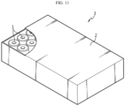
- FIG. 11 is a diagram showing the battery pack according to an embodiment of the present disclosure.
- the battery pack 3 may include at least one battery 1 of the present disclosure.
- the battery 1 may be accommodated in a pack housing 2.
- the battery pack 3 may include a component for electrical connection between the batteries 1 and/or a Battery management system (BMS) to control the charge and discharge of the battery 1.
- BMS Battery management system
- FIG. 12 is a diagram showing the vehicle according to an embodiment of the present disclosure.
- the vehicle 5 includes at least one battery pack 3.
- the vehicle 5 may be powered by the battery pack 3.
- the vehicle 5 may be, for example, a hybrid electric vehicle (HEV) or an electric vehicle (EV).
- HEV hybrid electric vehicle
- EV electric vehicle
Landscapes
- Chemical & Material Sciences (AREA)
- Chemical Kinetics & Catalysis (AREA)
- Electrochemistry (AREA)
- General Chemical & Material Sciences (AREA)
- Engineering & Computer Science (AREA)
- Manufacturing & Machinery (AREA)
- Aviation & Aerospace Engineering (AREA)
- Secondary Cells (AREA)
- Connection Of Batteries Or Terminals (AREA)
- Gas Exhaust Devices For Batteries (AREA)
Abstract
Description
- The present disclosure relates to a battery, and a battery pack and a vehicle comprising the same.
- The present application claims priority to
Korean Patent Application No. 10-2022-0089125 filed on July 19, 2022 - In general, secondary batteries are designed to reduce the internal pressure through gas venting when the internal pressure rises due to defects or failures. When the internal pressure is higher than a predetermined level, proper venting may prevent accidents such as explosion caused by continuous rise in internal pressure.
- However, when there are factors that hinder timely venting or structure destruction occurs due to the increased internal pressure, shorts may occur and thermal events may spread, resulting in very low safety of secondary batteries while in use.
- In thermal runaway tests for removing the hazard factors, there are short risks, for example, a portion of the electrode assembly may be ejected from a housing after venting.
- In the event of thermal runaway, the electrode assembly may be ejected from the housing too quickly, and as a consequence, internal shorts may occur in secondary batteries, or external shorts may occur due to the ejected electrode assembly and/or broken pieces of any other metal component.
- Besides, when the electrode assembly is ejected too quickly due to the rise in internal pressure and/or thermal events in the housing, the ejected portion of the electrode assembly may block the gas venting route before gas is vented by the partial rupture of the housing, resulting in poor venting. When proper venting fails, the internal pressure may notably rise, causing explosion.
- Accordingly, there is a need for the development of secondary battery structure for preventing or delaying the structural destruction of the electrode assembly caused by the increased internal pressure due to defects or failures in secondary batteries.
- The present disclosure is designed to address the above-described problem, and therefore the present disclosure is directed to preventing or delaying structural destruction of an electrode assembly when rises in internal pressure and/or thermal events occur due to defects or failures in a battery.
- However, the technical problem to be solved by the present disclosure is not limited to the above-described problems, and these and other problems will be clearly understood by those skilled in the art from the following description.
- To solve the above-described problem, a battery according to an embodiment of the present disclosure includes an electrode assembly having a winding center hole around which a stack is wound, the stack including a first electrode, a second electrode and a separator interposed between the first electrode and the second electrode; a housing accommodating the electrode assembly through an open portion on a side; and a current collector having a current collector hole having a larger diameter than a diameter of the winding center hole and disposed at a location corresponding to the winding center hole, and the current collector coupled to a surface of the electrode assembly on the side of the open portion of the housing.
- The winding center hole may be located on an inner side of the current collector hole.
- A value obtained by dividing a difference between the diameter of the current collector hole and the diameter of the winding center hole by the diameter of the winding center hole may be equal to or larger than 0.015 and smaller than 0.4.
- The diameter of the winding center hole may be equal to or larger than 5.0 mm and smaller than 7.0 mm.
- A difference between the diameter of the current collector hole and the diameter of the winding center hole may be equal to or larger than 0.1 and smaller than 2.0.
- The current collector may be electrically connected to the housing.
- The battery may include a cap covering the open portion.
- The cap may have a vent that is more vulnerable than a surrounding area to rupture when an internal pressure rises.
- Meanwhile, to solve the above-described problem, a battery pack according to an embodiment of the present disclosure includes the battery according to an embodiment of the present disclosure.
- To solve the above-described problem, a vehicle according to an embodiment of the present disclosure includes the battery pack according to an embodiment of the present disclosure.
- According to an aspect of the present disclosure, it may be possible to prevent or delay structural destruction of the electrode assembly when rises in internal pressure and/or thermal events occur due to defects or failures in the battery.
- However, the advantageous effects obtained through the present disclosure are not limited to the above-described effects, and these and other advantageous effects will be clearly understood by those skilled in the art from the following description.
- The accompanying drawings illustrate exemplary embodiments of the present disclosure and together with the following detailed description, serve to provide a further understanding of the technical aspect of the present disclosure, and thus the present disclosure should not be construed as being limited to the drawings.
-
FIG. 1 is a diagram showing an open upper portion of a battery according to an embodiment of the present disclosure. -
FIG. 2 is a top view showing a combination of an electrode assembly and a current collector of the present disclosure. -
FIG. 3 is a diagram showing the increasing normal reaction force with decreasing diameter of a winding center hole of an electrode assembly. -
FIG. 4 is a diagram showing the increasing frictional force with increasing normal reaction force at a core of an electrode assembly. -
FIGS. 5 to 7 are computed tomography (CT) images showing a change in ejection amount of an electrode assembly as a function of diameter of a winding center hole of the electrode assembly. -
FIG. 8 is a diagram showing an upper portion structure of a battery according to an embodiment of the present disclosure. -
FIG. 9 is a top view showing a vent in a cap of the present disclosure. -
FIG. 10 is a diagram showing a lower portion structure of a battery according to an embodiment of the present disclosure. -
FIG. 11 is a diagram showing a battery pack according to an embodiment of the present disclosure. -
FIG. 12 is a diagram showing a vehicle according to an embodiment of the present disclosure. - Hereinafter, exemplary embodiments of the present disclosure will be described in detail with reference to the accompanying drawings. Prior to the description, it should be understood that the terms or words used in the specification and the appended claims should not be construed as being limited to general and dictionary meanings, but rather interpreted based on the meanings and concepts corresponding to the technical aspect of the present disclosure on the basis of the principle that the inventor is allowed to define the terms appropriately for the best explanation. Therefore, the embodiments described herein and the illustrations shown in the drawings are exemplary embodiments of the present disclosure to describe the technical aspect of the present disclosure and are not intended to be limiting, so it should be understood that a variety of other equivalents and modifications could have been made thereto at the time that the application was filed.
- To begin with, a
battery 1 according to an embodiment of the present disclosure will be described with reference toFIGS. 1 and2 .FIG. 1 is a diagram showing an open upper portion of the battery according to an embodiment of the present disclosure.FIG. 2 is a top view showing a combination of an electrode assembly and a current collector of the present disclosure. - Referring to
FIGS. 1 and2 , thebattery 1 according to an embodiment of the present disclosure may be a cylindrical battery. Thebattery 1 may include anelectrode assembly 10, ahousing 20 and a current collector (a first current collector) 30. - The
electrode assembly 10 may have awinding center hole 10a formed by winding a stack including a first electrode, a second electrode and a separator interposed between the first electrode and the second electrode. The first electrode may have a firstuncoated portion 11 along a winding direction at an end portion. In this case, the firstuncoated portion 11 may be disposed on a surface of theelectrode assembly 10. - The
housing 20 may accommodate theelectrode assembly 10 through an open portion on a side. Although not shown inFIG. 1 , thehousing 20 may have a closed portion opposite the open portion. Thehousing 20 may include a conductive metal. AlthoughFIG. 1 shows that thehousing 20 is open on one side, the open portion may be closed by a separate component. - The
current collector 30 may be disposed on a surface of theelectrode assembly 10 on the side of the open portion of thehousing 20. Thecurrent collector 30 may be, for example, electrically coupled to the firstuncoated portion 11 of theelectrode assembly 10. The firstuncoated portion 11 may be formed at an end portion of the first electrode of theelectrode assembly 10. The firstuncoated portion 11 may extend along the winding direction of theelectrode assembly 10. The firstuncoated portion 11 may be disposed on a surface of theelectrode assembly 10, and for example, may extend in the upward direction of theelectrode assembly 10. Although not shown inFIG. 1 , thecurrent collector 30 may be configured to electrically connect the first electrode of theelectrode assembly 10 to thehousing 20. - The
current collector 30 may have acurrent collector hole 30a. Thecurrent collector hole 30a may be formed at a location corresponding to thewinding center hole 10a of theelectrode assembly 10. Thecurrent collector hole 30a may have a diameter R2 that is larger than a diameter R1 of the windingcenter hole 10a of theelectrode assembly 10. - As shown in
FIG. 2 , the windingcenter hole 10a of theelectrode assembly 10 may be located on the inner side of thecurrent collector hole 30a. That is, thecurrent collector 30 may be disposed so as not to cover even a portion of the windingcenter hole 10a of theelectrode assembly 10. - According to the above-described configuration of the present disclosure, when the combination of the
electrode assembly 10 and thecurrent collector 30 is received in thehousing 20 and an electrolyte solution is injected, circulation of the electrolyte solution through the windingcenter hole 10a may be very good. In another aspect, according to the above-described configuration of the present disclosure, it may be possible to easily perform a process of welding components such as terminals at the closed portion opposite the open portion of thehousing 20 by irradiating a laser for welding or inserting an instrument for welding through the windingcenter hole 10a. - In the case where the
current collector 30 covers even a portion of the windingcenter hole 10a of theelectrode assembly 10, it may result in poor flow circulation of the electrolyte solution in the process of injecting the electrolyte solution. In another aspect, in the case where thecurrent collector 30 covers even a portion of the windingcenter hole 10a of theelectrode assembly 10, it may result in a poor welding process through the windingcenter hole 10a and/or damage to the inner wall of the windingcenter hole 10a in the welding process. - Subsequently, a change in the extent of core deformation of the
electrode assembly 10 with a change in diameter of the windingcenter hole 10a of theelectrode assembly 10 will be described with reference toFIGS. 3 to 7 together withFIGS 1 and2 .FIG. 3 is a diagram showing the increasing normal reaction force with decreasing diameter of the winding center hole of the electrode assembly, andFIG. 4 is a diagram showing the increasing frictional force with increasing normal reaction force at the core of the electrode assembly.FIGS. 5 to 7 are computed tomography (CT) images showing a change in ejection amount of the electrode assembly as a function of the diameter of the winding center hole of the electrode assembly. - A core exposure ratio A or a product of dividing a difference between the diameter R2 of the
current collector hole 30a and the diameter R1 of the windingcenter hole 10a of theelectrode assembly 10 by the diameter R1 of the windingcenter hole 10a may be approximately 0.015 to 0.5. The core exposure ratio A may be equal to or larger than approximately 0.015 and smaller than 0.4. The core exposure ratio A may be equal to or larger than approximately 0.072 and smaller than 0.3. The core exposure ratio A may be approximately 0.016 to 0.5. The core exposure ratio A may be equal to or larger than approximately 0.016 and smaller than 0.4. The core exposure ratio A may be equal to or larger than approximately 0.077 and smaller than 0.3. The core exposure ratio A may be approximately 0.016 to 0.416. The core exposure ratio A may be approximately 0.016 to 0.333. The core exposure ratio A may be equal to or larger than approximately 0.077 and smaller than 0.25. - The diameter R1 of the winding
center hole 10a may be equal to or larger than approximately 5.0 mm and smaller than 7.0 mm. The diameter R1 of the windingcenter hole 10a may be equal to or larger than approximately 5.0 mm and smaller than approximately 6.5 mm. The diameter R1 of the windingcenter hole 10a may be equal to or larger than approximately 6.0 mm and smaller than 6.5 mm. - The difference (R2-R1) between the diameter R2 of the
current collector hole 30a and the diameter R1 of the windingcenter hole 10a may be approximately 0.1 mm to 2.5 mm. The difference (R2-R1) between the diameter R2 of thecurrent collector hole 30a and the diameter R1 of the windingcenter hole 10a may be equal to or larger than approximately 0.1 mm and smaller than 2.0 mm. The difference (R2-R1) between the diameter R2 of thecurrent collector hole 30a and the diameter R1 of the windingcenter hole 10a may be equal to or larger than approximately 0.5 mm and smaller than 1.5 mm. - For the above-described numerical range, core deformation suppression of the
electrode assembly 10, smooth circulation of the electrolyte solution, easy to perform the welding process and easy to align thecurrent collector 30 and theelectrode assembly 10 are taken into account. The influence of the diameter R1 of the windingcenter hole 10a and the diameter R2 of thecurrent collector hole 30a on the resistive force for the suppression of ejection at the core of theelectrode assembly 10 will be described in detail below. - Referring to
FIG. 3 together withFIGS. 1 and2 , when the diameter of the windingcenter hole 10a decreases, the normal reaction force applied outwards from the core of theelectrode assembly 10 increases. This is because as the windingcenter hole 10a of theelectrode assembly 10 is smaller, the curvature of theelectrode assembly 10 increases, leading to an increase in tension by the restoring force in the wound stack including the first electrode, the second electrode and the separator. - Referring to
FIG. 4 together withFIGS. 1 and2 , the resistive force to the ejection force at the core of theelectrode assembly 10 increases due to the increasing normal reaction force with the decreasing diameter R1 of the windingcenter hole 10a. This is because the frictional force between each adjacent layer of the stack including the first electrode, the second electrode and the separator increases with the increasing normal reaction force applied outwards from the core of theelectrode assembly 10. - The frictional force between each layer of the stack may act as the resistive force to the ejection force of the core of the
electrode assembly 10 caused by the rise in internal pressure of thebattery 1. Accordingly, when the frictional force increases, it may be possible to suppress the core ejection of theelectrode assembly 10. - Referring to
FIGS. 5 to 7 together withFIGS. 1 and2 , when core ejection of theelectrode assembly 10 occurs due to the rise in internal pressure of thebattery 1, it can be seen that as the windingcenter hole 10a of theelectrode assembly 10 is smaller, the core ejection length of theelectrode assembly 10 towards the open portion of thehousing 20 is shorter. InFIG. 5 , the diameter R1 of the windingcenter hole 10a is approximately 6 mm. InFIG. 6 , the diameter R1 of the windingcenter hole 10a is approximately 7 mm. InFIG. 7 , the diameter R1 of the windingcenter hole 10a is approximately 8 mm. InFIGS. 6 and7 , core ejection of theelectrode assembly 10 occurs due to thermal events in thebattery 1, but the ejected portion is not exposed to the outside of thebattery 1. In particular, it can be seen fromFIG. 5 that the core ejection length of theelectrode assembly 10 is very short. However, it can be seen fromFIG. 7 that the core ejection length of theelectrode assembly 10 is very long and theelectrode assembly 10 was ejected up to a location far away from the core of theelectrode assembly 10. - As described above, when the core ejection of the
electrode assembly 10 occurs to a great extent, additional thermal events may occur due to shorts caused by unnecessary electrical contact and/or gas venting may be hindered by the ejected portion. Accordingly, to cause the core ejection of theelectrode assembly 10 below a predetermined level, it is necessary to adjust the diameter R1 of the windingcenter hole 10a of theelectrode assembly 10 to the proposed level. - Meanwhile, a value obtained by dividing the diameter R1 of the winding
center hole 10a by the diameter of theelectrode assembly 10 may be approximately 0.109 to 0.159. The value obtained by dividing the diameter R1 of the windingcenter hole 10a by the diameter of theelectrode assembly 10 may be approximately 0.109 to 0.147. The value obtained by dividing the diameter R1 of the windingcenter hole 10a by the diameter of theelectrode assembly 10 may be approximately 0.130 to 0.147. - Meanwhile, a value obtained by dividing the difference between the diameter R2 of the
current collector hole 30a and the diameter R1 of the windingcenter hole 10a by the diameter of theelectrode assembly 10 may be approximately 0.002 to 0.056. The value obtained by dividing the difference between the diameter R2 of thecurrent collector hole 30a and the diameter R1 of the windingcenter hole 10a by the diameter of theelectrode assembly 10 may be approximately 0.002 to 0.045. The value obtained by dividing the difference between the diameter R2 of thecurrent collector hole 30a and the diameter R1 of the windingcenter hole 10a by the diameter of theelectrode assembly 10 may be approximately 0.011 to 0.034. - In addition to the absolute values of the diameter R1 of the winding
center hole 10a of theelectrode assembly 10 and the diameter R2 of thecurrent collector hole 30a, the resistive force for the suppression of core ejection of theelectrode assembly 10 may be affected by a ratio of the diameter R1 of the windingcenter hole 10a to the total diameter of theelectrode assembly 10. - The diameter of the
electrode assembly 10 of the present disclosure may be, for example, approximately 44 mm to 46 mm. - As described above, when the diameter R1 of the winding
center hole 10a is too large, it may result in inadequate suppression of core ejection of theelectrode assembly 10 when thermal events occur. Accordingly, in view of this, it is necessary to set the upper limit of the diameter R1 of the windingcenter hole 10a. - On the contrary, when the diameter R1 of the winding
center hole 10a is too small, it may result in poor circulation of the electrolyte solution through the windingcenter hole 10a and/or it may be difficult to perform the process of welding the components on the opposite side to the open portion of thehousing 20 through the windingcenter hole 10a. In particular, when the welding is performed by laser irradiation through the windingcenter hole 10a, a sufficient space may be needed for stable incidence of the laser within the windingcenter hole 10a. Accordingly, in view of this, it is necessary to set the lower limit of the diameter R1 of the windingcenter hole 10a. - Meanwhile, the diameter R2 of the
current collector hole 30a of thecurrent collector 30 may also affect the determination of the resistive force for the suppression of core ejection of theelectrode assembly 10. - When the diameter R2 of the
current collector hole 30a is too large, there is a reduction in suppression of core ejection of theelectrode assembly 10. Accordingly, in view of this, it is necessary to set the upper limit of the difference value between the diameter R2 of thecurrent collector hole 30a and the diameter R1 of the windingcenter hole 10a. - On the contrary, when the diameter R2 of the
current collector hole 30a is too small, it may be difficult to perform the alignment process of placing the windingcenter hole 10a in thecurrent collector hole 30a. When the windingcenter hole 10a is not accurately located in thecurrent collector hole 30a, a portion of the windingcenter hole 10a may be covered by thecurrent collector 30. This may hinder the injection/circulation of the electrolyte solution through the windingcenter hole 10a and the welding process through the windingcenter hole 10a. Accordingly, in view of this, it is necessary to set the lower limit of the difference value between the diameter R2 of thecurrent collector hole 30a and the diameter R1 of the windingcenter hole 10a.[Table 1] Hole diameter Core analysis after venting (TEST 1): Electrode assembly ejection probability 100% (4/4ea) R1: 8 mm Ejection length about 10 to 20 mm R2-R1: 0.5 mm (TEST 2): Electrode assembly ejection probability 87.5% (7/8ea) R1: 7 mm Ejection length about 0 to 15 mm R2-R1: 0.5 mm (TEST 3): Electrode assembly ejection probability 0% (0/5ea) R1: 6 mm Ejection length 0 mm R2-R1: 0.5 mm (TEST 4): Electrode assembly ejection probability 100% (4/4ea) R1: 8 mm Ejection length about 10 to 20 mm R2-R1: 0.5 mm (TEST 5): Electrode assembly ejection probability 100% (5/5ea) R1: 7mm Ejection length about 5 to 20 mm R2-R1: 1.5 mm (TEST 6): Electrode assembly ejection probability 0% (0/3ea) R1: 6 mm Ejection length 0 mm R2-R1: 2.5 mm (TEST 7): Electrode assembly ejection probability 83% (5/6ea) R1: 6.5 mm Ejection length about 10 to 30 mm R2-R1: 2 mm - Referring to the above Table 1 together with the above-referenced drawings, it can be seen that the results are generally good when the diameter of the winding
center hole 10a of theelectrode assembly 10 is smaller than approximately 7 mm. That is, it can be seen that in case where the diameter of the windingcenter hole 10a is smaller than approximately 7 mm, core deformation of theelectrode assembly 10 is suppressed when thermal events occur in thebattery 1. - Meanwhile, seeing the experimental results shown in Table 1, it can be seen that the core deformation suppression is affected by the difference between the diameter R2 of the
current collector hole 30a and the diameter R1 of the windingcenter hole 10a. It can be seen that when R1 is less than 7 mm and R2-R1 is approximately 2.5 mm or less, it may be possible to achieve adequate core deformation suppression. - However, as shown in TEST 5 and TEST 7, when R1 is 6.5 mm or more but R2-R1 is 2.5 mm or less, core deformation may occur. In view of this, it may be necessary to limit R1 to less than approximately 6.5 mm and/or limit R2-R1 to less than approximately 2.0 mm and/or limit R2-R1 to less than approximately 1.5 mm, to further improve the core deformation suppression effect.
- Subsequently, the whole structure of the
battery 1 according to an embodiment of the present disclosure will be described with reference toFIGS. 8 to 10 .FIG. 8 is a diagram showing an upper portion structure of the battery according to an embodiment of the present disclosure.FIG. 9 is a top view showing the vent in the cap of the present disclosure.FIG. 10 is a diagram showing a lower portion structure of the battery according to an embodiment of the present disclosure. - To begin with, referring to
FIGS. 8 and9 , thecurrent collector 30 may be electrically connected to thehousing 20. Thecurrent collector 30 may be, for example, electrically coupled to a beading portion extending inwards from the outer circumferential surface of thehousing 20. - The
battery 1 may include acap 40 to cover the open portion on a side of thehousing 20. Thecap 40 may be electrically insulated from theelectrode assembly 10 and thehousing 20, and may not be polar. For example, a first insulation member G1 may be interposed between thecap 40 and thehousing 20. - The
cap 40 may have avent 40a configured to rupture when the internal pressure of thebattery 1 increases. Thevent 40a may be more vulnerable than the surrounding area. For example, thevent 40a may be an area having a smaller thickness than the remaining area of thecap 40. Thevent 40a may extend, forming a closed loop in thecap 40 as shown inFIG. 8 . - When the
battery 1 of the present disclosure includes thecap 40 and thecap 40 has thevent 40a, it is more important to suppress the core ejection of theelectrode assembly 10 as described above. In the case where core ejection is not suppressed, before gas is vented by the rupture of thevent 40a of thecap 40, a space between thecap 40 and thecurrent collector 30 may be filled by the ejected core of theelectrode assembly 10. In this case, even though thevent 40a ruptures, adequate gas venting may fail, resulting in thermal event spread. - Referring to
FIG. 10 , thebattery 1 may include a first terminal T1. The first terminal T1 may be electrically coupled to a seconduncoated portion 12 of theelectrode assembly 10. In the similar way to the firstuncoated portion 11, the seconduncoated portion 12 may be formed at an end portion of the second electrode. The seconduncoated portion 12 may extend along the winding direction of theelectrode assembly 10. The seconduncoated portion 12 may be disposed on the opposite surface to the surface on which the firstuncoated portion 11 is present among two surfaces of theelectrode assembly 10, and for example, may extend in the downward direction of theelectrode assembly 10. A portion of the first terminal T1 may be, for example, inserted into thehousing 20 through the closed portion of thehousing 20. The first terminal T1 may be electrically insulated from thehousing 20. For example, a second insulation member G2 may be interposed between the first terminal T1 and thehousing 20. When the first terminal T1 is disposed on the side of the closed portion of thehousing 20, the outer surface of the closed portion of thehousing 20 may act as a second terminal T2. - The
battery 1 may include a current collector (a second current collector) P to electrically connect the first terminal T1 to theelectrode assembly 10. The current collector P may be electrically coupled to the first terminal T1. For example, the current collector P and the first terminal T1 may be welded by irradiating a laser or inserting an instrument for welding through the windingcenter hole 10a of theelectrode assembly 10 from the open portion of thehousing 20. - When the
battery 1 of the present disclosure includes the current collector P, an insulator IS may be interposed between the current collector P and the closed portion of thehousing 20. The insulator IS may prevent the contact between the current collector P and thehousing 20 having different polarities. - Subsequently, a
battery pack 3 according to an embodiment of the present disclosure will be described with reference toFIG. 11. FIG. 11 is a diagram showing the battery pack according to an embodiment of the present disclosure. - Referring to
FIG. 11 , thebattery pack 3 according to an embodiment of the present disclosure may include at least onebattery 1 of the present disclosure. Thebattery 1 may be accommodated in apack housing 2. Thebattery pack 3 may include a component for electrical connection between thebatteries 1 and/or a Battery management system (BMS) to control the charge and discharge of thebattery 1. - Subsequently, a vehicle 5 according to an embodiment of the present disclosure will be described with reference to
FIG. 12. FIG. 12 is a diagram showing the vehicle according to an embodiment of the present disclosure. - Referring to
FIG. 12 , the vehicle 5 according to an embodiment of the present disclosure includes at least onebattery pack 3. The vehicle 5 may be powered by thebattery pack 3. The vehicle 5 may be, for example, a hybrid electric vehicle (HEV) or an electric vehicle (EV). - While the present disclosure has been hereinabove described with regard to a limited number of embodiments and drawings, the present disclosure is not limited thereto and it is apparent that a variety of changes and modifications may be made by those skilled in the art within the technical aspect of the present disclosure and the scope of the appended claims and their equivalents.
-
- 1: Battery
- 2: Pack housing
- 3: Battery pack
- 5: Vehicle
- 10: Electrode assembly
- 11: First uncoated portion
- 12: Second uncoated portion
- 10a: Winding center hole
- 20: Housing
- 30: Current collector (First current collector)
- 30a: Current collector hole
- 40: Cap
- 40a: Vent
- T1: First terminal
- T2: Second terminal
- P: Current collector (Second current collector)
- IS: Insulator
Claims (10)
- A battery, comprising:an electrode assembly having a winding center hole around which a stack is wound, the stack including a first electrode, a second electrode and a separator interposed between the first electrode and the second electrode;a housing accommodating the electrode assembly through an open portion on a side; anda current collector having a current collector hole having a larger diameter than a diameter of the winding center hole and disposed at a location corresponding to the winding center hole, and the current collector coupled to a surface of the electrode assembly on the side of the open portion of the housing.
- The battery according to claim 1, wherein the winding center hole is located on an inner side of the current collector hole.
- The battery according to claim 1, wherein a value obtained by dividing a difference between the diameter of the current collector hole and the diameter of the winding center hole by the diameter of the winding center hole is equal to or larger than 0.015 and smaller than 0.4.
- The battery according to claim 1, wherein the diameter of the winding center hole is equal to or larger than 5.0 mm and smaller than 7.0 mm.
- The battery according to claim 1, wherein a difference between the diameter of the current collector hole and the diameter of the winding center hole is equal to or larger than 0.1 and smaller than 2.0.
- The battery according to claim 1, wherein the current collector is electrically connected to the housing.
- The battery according to claim 1, comprising:
a cap covering the open portion. - The battery according to claim 7, wherein the cap has a vent that is more vulnerable than a surrounding area to rupture when an internal pressure rises.
- A battery pack comprising the battery according to any one of claims 1 to 8.
- A vehicle comprising the battery pack according to claim 9.
Applications Claiming Priority (2)
| Application Number | Priority Date | Filing Date | Title |
|---|---|---|---|
| KR20220089125 | 2022-07-19 | ||
| PCT/KR2023/010443 WO2024019545A1 (en) | 2022-07-19 | 2023-07-19 | Battery, and battery pack and vehicle comprising same |
Publications (2)
| Publication Number | Publication Date |
|---|---|
| EP4496111A1 true EP4496111A1 (en) | 2025-01-22 |
| EP4496111A4 EP4496111A4 (en) | 2025-11-05 |
Family
ID=89618289
Family Applications (1)
| Application Number | Title | Priority Date | Filing Date |
|---|---|---|---|
| EP23843391.6A Pending EP4496111A4 (en) | 2022-07-19 | 2023-07-19 | BATTERY AND BATTERY PACK AS WELL AS VEHICLE WITH IT |
Country Status (6)
| Country | Link |
|---|---|
| EP (1) | EP4496111A4 (en) |
| JP (1) | JP2025526331A (en) |
| KR (1) | KR20240011645A (en) |
| CN (1) | CN118786572A (en) |
| CA (1) | CA3252770A1 (en) |
| WO (1) | WO2024019545A1 (en) |
Families Citing this family (1)
| Publication number | Priority date | Publication date | Assignee | Title |
|---|---|---|---|---|
| WO2026084500A1 (en) * | 2024-10-17 | 2026-04-23 | 삼성에스디아이 주식회사 | Secondary battery and battery pack comprising same |
Family Cites Families (12)
| Publication number | Priority date | Publication date | Assignee | Title |
|---|---|---|---|---|
| EP0819319A4 (en) * | 1994-07-06 | 1999-03-03 | Elmer Hughett | Electric vehicle cell |
| JP3972804B2 (en) * | 2002-11-21 | 2007-09-05 | 松下電器産業株式会社 | Alkaline storage battery and manufacturing method thereof |
| JP2005150073A (en) * | 2003-08-28 | 2005-06-09 | Matsushita Electric Ind Co Ltd | Battery and manufacturing method thereof |
| JP5196824B2 (en) * | 2007-03-29 | 2013-05-15 | 三洋電機株式会社 | Cylindrical battery and manufacturing method thereof |
| JP2008251199A (en) * | 2007-03-29 | 2008-10-16 | Matsushita Electric Ind Co Ltd | Electrode for alkaline storage battery and alkaline storage battery |
| JP2010080294A (en) * | 2008-09-26 | 2010-04-08 | Panasonic Corp | Secondary battery |
| KR101256743B1 (en) * | 2009-07-17 | 2013-04-19 | 파나소닉 주식회사 | Battery and battery unit |
| JP2018055812A (en) * | 2016-09-26 | 2018-04-05 | Fdk株式会社 | Current collecting lead, method for producing alkaline secondary battery including the current collecting lead, and alkaline secondary battery produced by this production method |
| JP7128666B2 (en) * | 2018-06-11 | 2022-08-31 | Fdk株式会社 | secondary battery |
| KR20220089125A (en) | 2020-12-21 | 2022-06-28 | 강교연 | Mask that can attach mask pack |
| CA3202295A1 (en) * | 2020-12-29 | 2022-07-07 | Lg Energy Solution, Ltd. | Cylindrical battery cell, and battery pack and vehicle comprising same |
| CN216250920U (en) * | 2021-10-20 | 2022-04-08 | 宁德时代新能源科技股份有限公司 | Battery cells, batteries and electrical equipment |
-
2023
- 2023-07-19 EP EP23843391.6A patent/EP4496111A4/en active Pending
- 2023-07-19 JP JP2025502676A patent/JP2025526331A/en active Pending
- 2023-07-19 WO PCT/KR2023/010443 patent/WO2024019545A1/en not_active Ceased
- 2023-07-19 KR KR1020230094088A patent/KR20240011645A/en active Pending
- 2023-07-19 CN CN202380024389.0A patent/CN118786572A/en active Pending
- 2023-07-19 CA CA3252770A patent/CA3252770A1/en active Pending
Also Published As
| Publication number | Publication date |
|---|---|
| CN118786572A (en) | 2024-10-15 |
| WO2024019545A1 (en) | 2024-01-25 |
| JP2025526331A (en) | 2025-08-13 |
| CA3252770A1 (en) | 2025-03-18 |
| KR20240011645A (en) | 2024-01-26 |
| EP4496111A4 (en) | 2025-11-05 |
Similar Documents
| Publication | Publication Date | Title |
|---|---|---|
| KR100477750B1 (en) | Electorde assembly for lithium ion cell and lithium ion cell using the same | |
| EP2136429B1 (en) | Electrode assembly and lithium secondary battery with same | |
| JP4230747B2 (en) | Secondary battery equipped with a thermo protector | |
| EP2924763B1 (en) | Secondary battery | |
| US8927123B2 (en) | Cap assembly of cylindrical rechargeable battery and cylindrical rechargeable battery | |
| WO2011037335A2 (en) | Secondary battery and method for manufacturing same | |
| KR20190033900A (en) | Cap Assembly for Cylindrical Battery Cell Comprising Elastic Member | |
| KR101975392B1 (en) | Rechargeable battery | |
| EP4496111A1 (en) | Battery, and battery pack and vehicle comprising same | |
| KR101006883B1 (en) | Battery containing electrolyte suction washer | |
| KR20070071232A (en) | Secondary battery having a vent and the vent forming method | |
| EP4235929B1 (en) | Secondary battery | |
| KR102522701B1 (en) | The Secondary Battery | |
| KR100416096B1 (en) | Safety valve device and secondary battery applying such | |
| US20230146853A1 (en) | Cylindrical secondary battery | |
| EP4231428A1 (en) | Secondary battery | |
| KR20230106935A (en) | Secondary Battery | |
| KR20220151467A (en) | Secondary Battery | |
| KR20130019713A (en) | Secondary battery and method for manufacturing the same | |
| KR102908460B1 (en) | Secondary battery with a vent | |
| KR20220033944A (en) | The Electrode Assembly And The Secondary Battery | |
| KR100571233B1 (en) | Secondary battery | |
| EP4468430A1 (en) | Electrode assembly, and secondary battery, battery pack, and transportation means comprising electrode assembly | |
| KR100635716B1 (en) | Secondary battery | |
| KR100472511B1 (en) | Lithium secondary battery without protection circuit module |
Legal Events
| Date | Code | Title | Description |
|---|---|---|---|
| STAA | Information on the status of an ep patent application or granted ep patent |
Free format text: STATUS: THE INTERNATIONAL PUBLICATION HAS BEEN MADE |
|
| PUAI | Public reference made under article 153(3) epc to a published international application that has entered the european phase |
Free format text: ORIGINAL CODE: 0009012 |
|
| STAA | Information on the status of an ep patent application or granted ep patent |
Free format text: STATUS: REQUEST FOR EXAMINATION WAS MADE |
|
| 17P | Request for examination filed |
Effective date: 20241016 |
|
| AK | Designated contracting states |
Kind code of ref document: A1 Designated state(s): AL AT BE BG CH CY CZ DE DK EE ES FI FR GB GR HR HU IE IS IT LI LT LU LV MC ME MK MT NL NO PL PT RO RS SE SI SK SM TR |
|
| DAV | Request for validation of the european patent (deleted) | ||
| DAX | Request for extension of the european patent (deleted) | ||
| A4 | Supplementary search report drawn up and despatched |
Effective date: 20251007 |
|
| RIC1 | Information provided on ipc code assigned before grant |
Ipc: H01M 50/538 20210101AFI20250930BHEP Ipc: H01M 10/04 20060101ALI20250930BHEP Ipc: H01M 50/342 20210101ALI20250930BHEP Ipc: H01M 10/0587 20100101ALN20250930BHEP |