EP4496074A1 - Battery pack - Google Patents
Battery pack Download PDFInfo
- Publication number
- EP4496074A1 EP4496074A1 EP23770701.3A EP23770701A EP4496074A1 EP 4496074 A1 EP4496074 A1 EP 4496074A1 EP 23770701 A EP23770701 A EP 23770701A EP 4496074 A1 EP4496074 A1 EP 4496074A1
- Authority
- EP
- European Patent Office
- Prior art keywords
- gas exhaust
- heat
- resistant member
- holder
- battery
- Prior art date
- Legal status (The legal status is an assumption and is not a legal conclusion. Google has not performed a legal analysis and makes no representation as to the accuracy of the status listed.)
- Granted
Links
Images


Classifications
-
- H—ELECTRICITY
- H01—ELECTRIC ELEMENTS
- H01M—PROCESSES OR MEANS, e.g. BATTERIES, FOR THE DIRECT CONVERSION OF CHEMICAL ENERGY INTO ELECTRICAL ENERGY
- H01M10/00—Secondary cells; Manufacture thereof
- H01M10/60—Heating or cooling; Temperature control
- H01M10/65—Means for temperature control structurally associated with the cells
- H01M10/658—Means for temperature control structurally associated with the cells by thermal insulation or shielding
-
- H—ELECTRICITY
- H01—ELECTRIC ELEMENTS
- H01M—PROCESSES OR MEANS, e.g. BATTERIES, FOR THE DIRECT CONVERSION OF CHEMICAL ENERGY INTO ELECTRICAL ENERGY
- H01M50/00—Constructional details or processes of manufacture of the non-active parts of electrochemical cells other than fuel cells, e.g. hybrid cells
- H01M50/30—Arrangements for facilitating escape of gases
- H01M50/342—Non-re-sealable arrangements
- H01M50/3425—Non-re-sealable arrangements in the form of rupturable membranes or weakened parts, e.g. pierced with the aid of a sharp member
-
- H—ELECTRICITY
- H01—ELECTRIC ELEMENTS
- H01M—PROCESSES OR MEANS, e.g. BATTERIES, FOR THE DIRECT CONVERSION OF CHEMICAL ENERGY INTO ELECTRICAL ENERGY
- H01M10/00—Secondary cells; Manufacture thereof
- H01M10/60—Heating or cooling; Temperature control
- H01M10/64—Heating or cooling; Temperature control characterised by the shape of the cells
- H01M10/643—Cylindrical cells
-
- H—ELECTRICITY
- H01—ELECTRIC ELEMENTS
- H01M—PROCESSES OR MEANS, e.g. BATTERIES, FOR THE DIRECT CONVERSION OF CHEMICAL ENERGY INTO ELECTRICAL ENERGY
- H01M50/00—Constructional details or processes of manufacture of the non-active parts of electrochemical cells other than fuel cells, e.g. hybrid cells
- H01M50/20—Mountings; Secondary casings or frames; Racks, modules or packs; Suspension devices; Shock absorbers; Transport or carrying devices; Holders
- H01M50/204—Racks, modules or packs for multiple batteries or multiple cells
- H01M50/207—Racks, modules or packs for multiple batteries or multiple cells characterised by their shape
- H01M50/209—Racks, modules or packs for multiple batteries or multiple cells characterised by their shape adapted for prismatic or rectangular cells
-
- H—ELECTRICITY
- H01—ELECTRIC ELEMENTS
- H01M—PROCESSES OR MEANS, e.g. BATTERIES, FOR THE DIRECT CONVERSION OF CHEMICAL ENERGY INTO ELECTRICAL ENERGY
- H01M50/00—Constructional details or processes of manufacture of the non-active parts of electrochemical cells other than fuel cells, e.g. hybrid cells
- H01M50/20—Mountings; Secondary casings or frames; Racks, modules or packs; Suspension devices; Shock absorbers; Transport or carrying devices; Holders
- H01M50/204—Racks, modules or packs for multiple batteries or multiple cells
- H01M50/207—Racks, modules or packs for multiple batteries or multiple cells characterised by their shape
- H01M50/213—Racks, modules or packs for multiple batteries or multiple cells characterised by their shape adapted for cells having curved cross-section, e.g. round or elliptic
-
- H—ELECTRICITY
- H01—ELECTRIC ELEMENTS
- H01M—PROCESSES OR MEANS, e.g. BATTERIES, FOR THE DIRECT CONVERSION OF CHEMICAL ENERGY INTO ELECTRICAL ENERGY
- H01M50/00—Constructional details or processes of manufacture of the non-active parts of electrochemical cells other than fuel cells, e.g. hybrid cells
- H01M50/30—Arrangements for facilitating escape of gases
- H01M50/35—Gas exhaust passages comprising elongated, tortuous or labyrinth-shaped exhaust passages
- H01M50/367—Internal gas exhaust passages forming part of the battery cover or case; Double cover vent systems
-
- H—ELECTRICITY
- H01—ELECTRIC ELEMENTS
- H01M—PROCESSES OR MEANS, e.g. BATTERIES, FOR THE DIRECT CONVERSION OF CHEMICAL ENERGY INTO ELECTRICAL ENERGY
- H01M50/00—Constructional details or processes of manufacture of the non-active parts of electrochemical cells other than fuel cells, e.g. hybrid cells
- H01M50/20—Mountings; Secondary casings or frames; Racks, modules or packs; Suspension devices; Shock absorbers; Transport or carrying devices; Holders
- H01M50/289—Mountings; Secondary casings or frames; Racks, modules or packs; Suspension devices; Shock absorbers; Transport or carrying devices; Holders characterised by spacing elements or positioning means within frames, racks or packs
- H01M50/291—Mountings; Secondary casings or frames; Racks, modules or packs; Suspension devices; Shock absorbers; Transport or carrying devices; Holders characterised by spacing elements or positioning means within frames, racks or packs characterised by their shape
-
- H—ELECTRICITY
- H01—ELECTRIC ELEMENTS
- H01M—PROCESSES OR MEANS, e.g. BATTERIES, FOR THE DIRECT CONVERSION OF CHEMICAL ENERGY INTO ELECTRICAL ENERGY
- H01M50/00—Constructional details or processes of manufacture of the non-active parts of electrochemical cells other than fuel cells, e.g. hybrid cells
- H01M50/20—Mountings; Secondary casings or frames; Racks, modules or packs; Suspension devices; Shock absorbers; Transport or carrying devices; Holders
- H01M50/289—Mountings; Secondary casings or frames; Racks, modules or packs; Suspension devices; Shock absorbers; Transport or carrying devices; Holders characterised by spacing elements or positioning means within frames, racks or packs
- H01M50/293—Mountings; Secondary casings or frames; Racks, modules or packs; Suspension devices; Shock absorbers; Transport or carrying devices; Holders characterised by spacing elements or positioning means within frames, racks or packs characterised by the material
-
- H—ELECTRICITY
- H01—ELECTRIC ELEMENTS
- H01M—PROCESSES OR MEANS, e.g. BATTERIES, FOR THE DIRECT CONVERSION OF CHEMICAL ENERGY INTO ELECTRICAL ENERGY
- H01M50/00—Constructional details or processes of manufacture of the non-active parts of electrochemical cells other than fuel cells, e.g. hybrid cells
- H01M50/30—Arrangements for facilitating escape of gases
- H01M50/35—Gas exhaust passages comprising elongated, tortuous or labyrinth-shaped exhaust passages
- H01M50/358—External gas exhaust passages located on the battery cover or case
-
- Y—GENERAL TAGGING OF NEW TECHNOLOGICAL DEVELOPMENTS; GENERAL TAGGING OF CROSS-SECTIONAL TECHNOLOGIES SPANNING OVER SEVERAL SECTIONS OF THE IPC; TECHNICAL SUBJECTS COVERED BY FORMER USPC CROSS-REFERENCE ART COLLECTIONS [XRACs] AND DIGESTS
- Y02—TECHNOLOGIES OR APPLICATIONS FOR MITIGATION OR ADAPTATION AGAINST CLIMATE CHANGE
- Y02E—REDUCTION OF GREENHOUSE GAS [GHG] EMISSIONS, RELATED TO ENERGY GENERATION, TRANSMISSION OR DISTRIBUTION
- Y02E60/00—Enabling technologies; Technologies with a potential or indirect contribution to GHG emissions mitigation
- Y02E60/10—Energy storage using batteries
Definitions
- the present disclosure relates to a battery pack.
- a nonaqueous electrolyte secondary battery such as a lithium-ion battery is used in the form of a battery pack in which a plurality of cells (batteries) is electrically connected and housed in a case. If there is an abnormality in the cells in the battery pack and one cell is abnormal and undergoes thermal runaway, a chain of thermal runaways may occur successively when a high-temperature gas is discharged from the cell and brought into contact with the surrounding cells. In a battery pack in which gas exhaust valves face each other, since the space between the facing cells is narrow, the battery pack is susceptible to thermal runaway cells. This problem is particularly remarkable in ultra-narrow battery packs with increased energy density.
- Patent Literature 1 describes a power supply device (battery pack) in which a heat-resistant sheet is arranged in the center between gas exhaust valves of cells arranged to face each other, and exhaust chambers (gas exhaust paths) are provided on both sides of the heat-resistant sheet.
- An object of the present disclosure is to provide a battery pack that can be miniaturized and can suppress a chain reaction of thermal runaways to the cells facing each other, even when a cell undergoes a thermal runaway.
- a battery pack according to the present disclosure includes a plurality of battery blocks each including a gas exhaust surface, the gas exhaust surfaces of the plurality of battery blocks facing each other, and a heat-resistant member arranged between the gas exhaust surfaces facing each other and forming gas exhaust paths between the heat-resistant member and each of the gas exhaust surfaces facing each other.
- Each of the plurality of battery blocks includes a plurality of cells each including a gas exhaust valve, and a holder holding the plurality of cells and aligning the gas exhaust valves of the plurality of cells on a holder end surface of the holder to form the gas exhaust surfaces.
- the heat-resistant member is fixed between the holder end surfaces of the plurality of battery blocks, the holder end surfaces facing each other, and displaceable to widen a corresponding one of the gas exhaust paths in response to a pressure of gas exhausted from an abnormal cell among the plurality of battery cells.
- a battery pack according to the present disclosure can be miniaturized, and can suppress a chain reaction of thermal runaways to another cell which the one cell faces even if one cell undergoes thermal runaway.
- FIG. 1 is an external view of battery pack 10 according to the present disclosure.
- Battery pack 10 includes outer covering case 20 made of metal such as aluminum, and a plurality of battery blocks 30 housed inside outer covering case 20, and heat-resistant member 36 arranged between the plurality of battery blocks 30.
- outer covering case 20 is not limited to be made of metal and may be made of resin.
- Battery block 30 includes a plurality of cells 31 arranged in line, and the plurality of cells 31 is electrically connected to each other.
- a plurality of cells 31 is, for example, electrically connected in parallel.
- Battery pack 10 includes a plurality of battery blocks 30 electrically connected in series or in parallel to output a voltage suitable for respective devices to be used.
- Cell 31 is, for example, a cylindrical battery. Note here that in this disclosure, a cylindrical battery is described as an example of cell 31, but a battery is not limited to a cylindrical battery, and may be a prismatic battery or the like.
- battery block 30 includes a plurality of battery cells 31 each including gas exhaust valve 31c and holder 32.
- Holder 32 includes gas exhaust surface 30a in which gas exhaust valves 31c of the plurality of cells 31 are aligned on an end surface of holder 32.
- Battery pack 10 includes a terminal plate (current collector plate) to which the plurality of battery blocks 30 is electrically connected.
- a positive electrode terminal and a negative electrode terminal of battery block 30 are respectively connected to the terminal plate.
- the terminal plate may be integrated with holder 32 described later.
- Cell 31 is a cylindrical battery including a bottomed cylindrical outer covering can and a sealing body that closes an opening part of the outer covering can. Furthermore, an insulating gasket is provided between the outer covering can and the sealing body.
- the sealing body serves as a positive electrode terminal
- the outer covering can serves as a negative electrode terminal.
- the sealing body includes gas exhaust valve 31c (see FIG. 4 ), on cell end surface 31a, for exhausting gas when an abnormality occurs in cell 31 and the internal pressure rises. Note here that gas exhaust valve 31c may be provided on the bottom of the outer covering can.
- External terminal 40 electrically connected to battery block 30 is provided on the end part of exterior case 20. External terminal 40 is used as a terminal for applying a DC voltage to a device into which battery pack 10 is to be installed. Furthermore, external terminal 40 is used also in charging battery pack 10 (cells 31). External terminal 40 may be provided at only one end part of battery pack 10, or may be provided in a plurality of places.
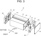
- FIG. 2 is an external view of battery block 30, and FIG. 3 is an exploded view of battery block 30.
- the longitudinal direction of battery block 30 is the vertical direction, and the lateral direction in which cells 31 are aligned is the horizontal direction.
- Battery block 30 is in a columnar shape composed of upper and lower holders 32 and side members 33.
- the shape of battery block 30 can be various shapes, such as a polygonal prismatic shape or a circular columnar shape, depending on arrangement of the plurality of cells 31 to be housed and the intended use of battery pack 10.
- battery block 30 includes heat insulating member 34 arranged between adjacent cells 31 of side surface member 33.
- Heat insulating member 34 acts as a heat insulating material to block heat from cell side surface 31b and prevent heat from being transferred to adjacent cell 31.
- Side surface member 33 covers the entire part of a plurality of cells 31 in battery block 30 except for cell end surfaces 31a, and holds cells 31.
- Side surface member 33 is formed of, for example, a highly thermally conductive material including a thermosetting resin, a thermally conductive filler, and/or an endothermic filler.
- Side surface member 33 is configured to be in contact with cell side surface 31b and to transfer heat to side surface member 33 when abnormal heat generation occurs in cell 31.
- the resin constituting side surface member 33 thermosetting unsaturated polyester, epoxy resin, melamine resin, and phenol resin, thermoplastic polycarbonate, polyethylene, polypropylene, polyvinyl chloride, polystyrene, and the like, are used.
- the thermally conductive filler a metal oxide (for example, aluminum oxide, and zinc oxide), a metal nitride (for example, aluminum nitride, and boron nitride), or a metal oxynitride (for example, aluminum oxynitride) is used.
- the endothermic filler exhibits an endothermic action during thermal decomposition, and, for example, aluminum hydroxide, magnesium hydroxide, and sodium hydrogen carbonate are used.
- the endothermic filler shows an effect of reducing heat generation when abnormal heat generation occurs in cell 31.
- Heat insulating member 34 is arranged between two adjacent cells 31 along the axial direction of cells 31.
- Heat insulating member 34 is made of, for example, heat insulating resin, foamed resin, foamed concrete, gypsum board, glass wool, or silica aerogel heat insulating materials.
- Heat insulating member 34 is formed in a flat plate shape in FIG. 3 , but it may have a curved surface depending on the shape of the side surface of cell 31.
- a length along the longitudinal direction (axial direction) of cells 31 in side surface member 33 and heat insulating member 34 is formed to be smaller than a length in the axial direction of cell 31. Therefore, as shown in FIG. 3 , cell end surfaces 31a on both sides of cell 31 in the axial direction protrude from side surface member 33.
- Holder 32 includes first and second holder members that respectively face both end surfaces of the plurality of cells 31 in the longitudinal direction, and is made of, for example, thermosetting resin.
- Holder 32 is a member for holding cell end surfaces 31a that protrude upward and downward from side surface member 33 from both sides in the longitudinal directions of plurality of cells 31, and plays the role of maintaining the shape of battery block 30 together with side surface member 33.
- Holder 32 further includes opening part 32a at a position corresponding to cell end surface 31a on the end surface of holder 32, and is also used for connecting an external electrode terminal to cell end surface 31a forming a positive electrode terminal or a negative electrode terminal. Opening part 32a also serves as a gas exhaust path when cell 31 is abnormal.
- holder 32 includes housing part 32b with a shape corresponding to cell end surface 31a.
- Housing part 32b includes bottom surface part 32c that is a surface facing cell end surface 31a, and a side surface part along cell side surface 31b from bottom surface part 32c.
- Two battery blocks 30 are bonded such that gas exhaust valves 31c of cells 31 of each battery block 30 are arranged opposite to each other.
- Columnar parts 32d provided on the first holder member near the top surface of holder 32 are butted against each other, and housed integrally with exterior case 20 of battery pack 10.
- Sheet-like heat-resistant member 36 is arranged in a space formed by butting columnar parts 32d against each other. Heat-resistant member 36 is provided so that gas discharged from cell end surface 31a of abnormally heated cell 31 does not hit the other directly facing cell end surface 31a, and serves to release the gas in the left-right direction (a direction perpendicular to the axial direction).
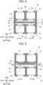
- FIG. 4 is a sectional view of two battery blocks 30, and the two battery blocks 30 are arranged such that gas exhaust valves 31c of cells 31 face each other.
- the direction in which the plurality of battery blocks 30 is aligned is the vertical direction
- the direction in which cells 31 are aligned inside battery block 30 is the left-right direction
- the back side perpendicular to the page is the depth direction
- the reverse side is the forward direction.
- a plurality of battery blocks 30 shown in FIG. 4 may be arranged in the vertical direction and the left-right direction, or in the depth direction.
- the number of cells 31 in battery block 30 is not limited to two, and may be three or more.
- left and right side surfaces 32f of holder 32 protrude more than holder end surface 32e.
- one battery block 30 and another battery block 30 are butted against each other with heat-resistant member 36 sandwiched therebetween and are housed integrally in outer covering case 20 of battery pack 10.
- Heat-resistant member 36 is provided as a blocking wall to prevent gas exhausted from gas exhaust valve 31c due to thermal runaway of a first cell 31 from directly hitting gas exhaust valve 31c of a second cell 31 facing the first cell 31.
- a space between each holder end surface 32e provided with gas exhaust valve 31c of cell 31 and heat-resistant member 36, gas exhaust path 37 is formed. However, as described later, in gas exhaust path 37 in a state shown in FIG. 4 , since a distance between holder end surface 32e and heat-resistant member 36 is short, a sufficient size for exhausting gas is not secured.
- FIG. 4 shows a sectional view of a plurality of battery blocks 30 in which gas exhaust valves 31c of cells 31 are arranged to face each other.
- FIG. 5 is a view for illustrating a mechanism in which gas exhaust path 37 widens when cell 31 that undergoes thermal runaway (hereinafter, also referred to as an abnormal cell) exhausts gas in battery pack 10 of FIG. 4 .
- the gas exhaust structure of battery pack 10 of the present disclosure includes battery blocks 30 arranged facing each other, heat-resistant member 36 arranged between battery blocks 30, and gas exhaust path 37 between battery blocks 30 and heat-resistant member 36.
- the plurality of battery blocks 30 includes gas exhaust surfaces 30a formed by aligning gas exhaust valves 31c of the plurality of cells 31 with respect to holder end surface 32e.
- the plurality of battery blocks 30 is arranged so that gas exhaust surfaces 30a face each other with heat-resistant member 36 sandwiched between gas exhaust surfaces 30a.
- Heat-resistant member 36 is arranged between gas exhaust surfaces 30a facing each other. Heat-resistant member 36 is sandwiched and fixed between side surfaces 32f of holder 32 at both ends in the left-right direction. Gas exhaust path 37 is formed between each surface in the vertical direction of heat-resistant member 36 and facing gas exhaust surfaces 30a.
- Heat-resistant member 36 of this exemplary embodiment includes deformable part 36a deformed in response to gas exhausted from abnormal cell 31.
- Deformable part 36a of heat-resistant member 36 of this exemplary embodiment shown in FIG. 4 is configured by a notch formed near side surface 32f of holder 32 at both left and right sides.
- Deformable part 36a is formed so as to break in response to a pressure of gas exhausted from abnormal cell 31.
- heat-resistant member 36 can be displaced so as to widen gas exhaust path 37 between holder end surfaces 32e facing each other.
- the configuration of deformable part 36a is not limited to a notch.
- Deformable part 36a can be formed by reducing a thickness of heat-resistant member 36.
- deformable part 36a in the present disclosure is not necessarily broken and separated from other sites, but also configured by a melting part that melts in response to a high-temperature gas exhausted from abnormal cell 31, and it may be configured that the melting part melts, and is separated from other sites.
- the shape may be deformed so as to widen gas exhaust path 37 in response to a pressure of gas.
- Abnormal cell 31A exhausts high-temperature and high-pressure gas upward from gas exhaust valve 31c.
- Deformable part 36a of heat-resistant member 36 breaks in response to a pressure of exhausted gas is received.
- Heat-resistant member 36 is separated at deformable part 36a, becomes movable between holder end surfaces 32e, and is pushed upward in response to the exhaust gas from abnormal cell 31A.
- gas exhaust path 37 above gas exhaust valve 31c of abnormal cell 31A and gas exhaust valve 31c of adjacent cell 31B is widened.
- the gas exhausted from abnormal cell 31A hits heat-resistant member 36 at the upper side and flows in the left-right direction in FIG. 5 , and pushes out pieces of heat-resistant member 36 sandwiched between side surfaces 32f of holder 32, and the gas is exhausted to the outside in the paths shown by arrows A and B.
- the gas exhausted from abnormal cell 31A is vigorously exhausted to the outside via the path indicated by the arrow B, and gas exhaust valve 31c of adjacent cell 31B undergoes little thermal influence.
- heat-resistant member 36 prevents cell 31 arranged facing the upper side of abnormal cell 31A from directly receiving the high-temperature gas.
- heat-resistant member 36 is arranged between holder end surfaces 32e facing each other. In a normal state, the size of formed gas exhaust path 37 is not secured to be sufficient, but heat-resistant member 36 is configured to be displaced to widen gas exhaust path 37 by pressure of gas exhausted from abnormal cell 31A. As a result, when abnormal cell 31A exhausts gas, gas exhaust path 37 in front of abnormal cell 31A widens, allowing the exhaust gas to be exhausted to the outside, and the chain reaction of thermal runaways to facing cell 31 can be suppressed.
- heat-resistant member 36 between holder end surfaces 32e facing each other is described.
- a structure in which heat-resistant member 36 is movable between holder end surfaces 32e facing each other is also considered.
- this structure can be achieved by making the width of heat-resistant member 36 smaller than the width of the left and right sides of holder 32, and not fixing heat-resistant member 36.
- heat-resistant member 36 moves toward the facing holder end surface 32e in response to the pressure of gas, so that the influence of heat on facing cell 31 is suppressed, and gas exhaust path 37 can be widened.
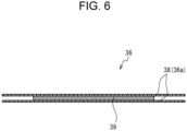
- FIG. 6 is an example of the configuration of heat-resistant member 36 in battery pack 10 of the present disclosure.
- Heat-resistant member 36 in FIG. 6 includes hard plate 39 and two protective sheets 38 covering both surfaces of hard plate 39.
- Hard plate 39 is a metal plate and is made of, for example, stainless steel (SUS). Hard plate 39 acts to block heat of high-temperature gas exhausted from abnormal cell 31 so that facing cell 31 is not affected by the heat.
- SUS stainless steel
- Protective sheet 38 is formed of, for example, a sheet including an insulating material such as flame-retardant fibers or mica. Protective sheet 38 is formed to cover the entire part of hard plate 39. The end of protective sheet 38 extending more than the end of hard plate 39 is sandwiched and fixed between side surfaces 32f of holder 32. The peripheral part extending from the end of hard plate 39 of protective sheet 38 is provided with perforations or the like, and formed so as to break in response to a pressure of gas from abnormal cell 31, and acts as deformable part 36a.
- hard plate 39 blocks directly hitting of high-temperature gas to facing cell 31, and when deformable part 36a of protective sheet 38 breaks, hard plate 39 is displaced between holder end surfaces 32e facing each other and acts so as to widen gas exhaust path 37.
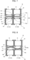
- FIG. 7 shows a gas exhaust structure of battery pack 10 of a second exemplary embodiment.
- the same reference numerals are given to component elements similar to those in the first exemplary embodiment, and detailed description thereof will be omitted.
- Battery block 30 of battery pack 10 of this exemplary embodiment includes protruding part 32g that protrudes perpendicularly from each holder end surface 32e.
- Protruding part 32g brings holder end surfaces 32e facing each other into contact with each other to form a circular columnar link part 32h.
- Link part 32h is, for example, a columnar site that links the centers of holder end surfaces 32e facing each other.
- left and right side surfaces 32f of holder end surface 32e are opened.
- Battery blocks 30 facing each other may be configured to be linked only by link part 32h.
- the side surfaces of holder 32 in the depth direction and the forward direction in FIG. 7 may be linked.
- Protruding part 32g includes claw parts 32i on the left and right sides.
- Claw part 32i is formed on the side surface of protruding part 32g so as to widen in the direction in which protruding part 32g protrudes from holder end surface 32e.
- Claw part 32i does not need to be formed on the entire periphery of protruding part 32g, and may be formed only on the left and right side surfaces of protruding part 32g in FIG. 5 .
- Claw part 32i may be integrally formed with protruding part 32g, or may be attached using adhesives or the like.
- Heat-resistant member 36 of this exemplary embodiment includes hole 36b in the center through which link part 32h can pass. Heat-resistant member 36 is formed so that when link part 32h is allowed to pass through hole 36b and holder end surfaces 32e facing each other are abutted, heat-resistant member 36 is fixed between upper and lower claw parts 32i.
- Arrangement of battery block 30 and heat-resistant member 36 shown in FIG. 7 is in a normal state. Therefore, in this state, the distance between holder end surfaces 32e facing each other is made to be small and the distance between holder end surface 32e and heat-resistant member 36 is short, so that the size of gas exhaust path 37 is not sufficient for exhausting gas.
- heat-resistant member 36 is displaced so as to widen gas exhaust path 37 in response to a pressure of gas exhausted from abnormal cell 31A, and a chain reaction of thermal runaways can be suppressed.
- FIG. 8 shows a gas exhaust structure of battery pack 10 of a third exemplary embodiment.
- Left and right side surfaces 32f of holder end surface 32e of battery block 30 shown in FIG. 8 are open, but battery block 30 is linked by the side surfaces of holder 32 in the depth direction and the forward direction in FIG. 8 .
- Heat-resistant member 36 of this exemplary embodiment is made of a sheet-like elastic material.
- the length of heat-resistant member 36 in the left-right direction is formed to be longer than the length of holder end surface 32e in the left-right direction.
- heat-resistant member 36 becomes S-shaped as shown in FIG. 8 , end surfaces of heat-resistant member 36 support holder end surface 32e to be fixed.
- the arrangement of battery block 30 and heat-resistant member 36 shown in FIG. 8 is in a normal state. Therefore, in this state, since the distance between holder end surfaces 32e facing each other is formed small, and a distance between holder end surface 32e and heat-resistant member 36 is short, the size of gas exhaust path 37 is not secured to be sufficient for exhausting gas. That is to say, heat-resistant member 36 is arranged so as to be in contact with gas exhaust valve 31c of cell 31B at the lower right side. The same is true to cell 31 at the upper left side.
- heat-resistant member 36 that comes into contact with gas exhaust valve 31c of abnormal cell 31B is pushed upward. Furthermore, due to the gas pressure, heat-resistant member 36 is deformed along the shape of holder end surface 32e at the upper side, and gas exhaust path 37 above abnormal cell 31B and cell 31A at the left thereof is widened. Thereby, gas exhausted from cell 31B is exhausted to the outside from the opening in side surface 32f of holder 32.
- heat-resistant member 36 in a normal state is not limited to an S-shape shown in FIG. 8 .
- the shape may be a U-shape, a C-shape, or the like, as long as heat-resistant member 36 is bent and fixed in contact with holder end surface 32e.
- heat-resistant member 36 is preferably formed of a thin sheet shape that is easily deformable.
- FIG. 9 shows a gas exhaust structure of battery pack 10 of a fourth exemplary embodiment.
- a structure of holder 32 is similar to that of battery pack 10 shown in FIG. 8 .
- Heat-resistant member 36 of this exemplary embodiment includes elastic part 36d formed of an elastic material and curved in a C-shape that opens upward, and plate-shaped part 36e pressed downward by the elastic power of elastic part 36d.
- Plate-shaped part 36e is formed of a metal plate or the like whose surface is insulated.
- Plate-like part 36e is formed in a size that closes opening part 32a of holder end surface 32e.
- the arrangement of battery block 30 and heat-resistant member 36 shown in FIG. 9 is usually in a normal state. Therefore, for cell 31 at the lower side, plate-shaped part 36e closes holder end surface 32e, and gas exhaust path 37 is not substantially formed. On the other hand, for cell 31 at the upper side, gas exhaust path 37 can be secured.
- the width of elastic part 36d in the depth direction is formed to be smaller than the width of holder end surface 32e in the depth direction. Thereby, elastic part 36d can be shaped to close only a part of side surface 32f of holder 32.
- plate-shaped part 36e When an abnormality occurs in lower cell 31, plate-shaped part 36e is pushed upward by a gas pressure. Since elastic part 36d is made of an elastic material, elastic part 36d is deformed so as to be crushed by the gas pressure, and plate-like part 36e is pushed up to holder end surfaces 32e facing each other. Thus, plate-shaped part 36e is displaced so that gas exhaust path 37 widens above lower cell 31. The gas discharged from abnormal cell 31 hits plate-shaped part 36e and is exhausted from the left and right openings.
- elastic part 36d is made of an elastic material curved in a C-shape
- elastic part 36d is not limited to this example, and may be made of an elastic material whose cross section is bent in a wave shape as long as the shape is elastically deformable.
- 10 battery pack 20 outer covering case, 30 battery block, 30a gas exhaust surface, 31 cell, 31a cell end surface, 31b cell side surface, 31c gas exhaust valve, 32 holder, 32a opening part, 32b housing part, 32c bottom surface part, 32d columnar part, 32e holder end surface, 32f side surface, 32g protruding part, 32h link part, 32i claw part, 33 side surface member, 34 heat insulating member, 36 heat-resistant member, 36a deformable part, 36b hole, 36c elastic part, 36d plate-shaped part, 37 gas exhaust path, 38 protective sheet, 39 hard plate, 40 external terminal
Landscapes
- Chemical & Material Sciences (AREA)
- Chemical Kinetics & Catalysis (AREA)
- Electrochemistry (AREA)
- General Chemical & Material Sciences (AREA)
- Engineering & Computer Science (AREA)
- Manufacturing & Machinery (AREA)
- Battery Mounting, Suspending (AREA)
- Gas Exhaust Devices For Batteries (AREA)
Abstract
Description
- The present disclosure relates to a battery pack.
- A nonaqueous electrolyte secondary battery such as a lithium-ion battery is used in the form of a battery pack in which a plurality of cells (batteries) is electrically connected and housed in a case. If there is an abnormality in the cells in the battery pack and one cell is abnormal and undergoes thermal runaway, a chain of thermal runaways may occur successively when a high-temperature gas is discharged from the cell and brought into contact with the surrounding cells. In a battery pack in which gas exhaust valves face each other, since the space between the facing cells is narrow, the battery pack is susceptible to thermal runaway cells. This problem is particularly remarkable in ultra-narrow battery packs with increased energy density.
- In order to prevent a chain reaction of thermal runaways caused by high-temperature gas, it is necessary to prevent contact with high-temperature gas generated from abnormal cells. Patent Literature 1 describes a power supply device (battery pack) in which a heat-resistant sheet is arranged in the center between gas exhaust valves of cells arranged to face each other, and exhaust chambers (gas exhaust paths) are provided on both sides of the heat-resistant sheet.
-
- In the structure of the battery pack of Patent Literature 1, a gas exhaust path is formed between gas exhaust valves of both cells facing each other and a heat-resistant sheet. Therefore, it is necessary to provide a sufficient distance between the gas exhaust valves of the cells facing each other, resulting in increasing the size of the battery pack and decreasing energy density.
- An object of the present disclosure is to provide a battery pack that can be miniaturized and can suppress a chain reaction of thermal runaways to the cells facing each other, even when a cell undergoes a thermal runaway.
- A battery pack according to the present disclosure includes a plurality of battery blocks each including a gas exhaust surface, the gas exhaust surfaces of the plurality of battery blocks facing each other, and a heat-resistant member arranged between the gas exhaust surfaces facing each other and forming gas exhaust paths between the heat-resistant member and each of the gas exhaust surfaces facing each other. Each of the plurality of battery blocks includes a plurality of cells each including a gas exhaust valve, and a holder holding the plurality of cells and aligning the gas exhaust valves of the plurality of cells on a holder end surface of the holder to form the gas exhaust surfaces. The heat-resistant member is fixed between the holder end surfaces of the plurality of battery blocks, the holder end surfaces facing each other, and displaceable to widen a corresponding one of the gas exhaust paths in response to a pressure of gas exhausted from an abnormal cell among the plurality of battery cells.
- A battery pack according to the present disclosure can be miniaturized, and can suppress a chain reaction of thermal runaways to another cell which the one cell faces even if one cell undergoes thermal runaway.
-
-
FIG. 1 is an external view of a battery pack according to the present disclosure. -
FIG. 2 is an external view of a battery block according to the present disclosure. -
FIG. 3 is an exploded view of the battery block ofFIG. 2 . -
FIG. 4 is a sectional view illustrating a gas exhaust structure of the battery pack according to the present disclosure. -
FIG. 5 is a view illustrating a mechanism in which a gas exhaust path of the battery pack ofFIG. 4 is widened. -
FIG. 6 is an example of a structure of a heat-resistant member of the present disclosure. -
FIG. 7 is a sectional view illustrating a second gas exhaust structure of the battery pack according to the present disclosure. -
FIG. 8 is a sectional view illustrating a third gas exhaust structure of the battery pack according to the present disclosure. -
FIG. 9 is a sectional view illustrating a fourth gas exhaust structure of the battery pack according to the present disclosure. - Hereinafter, the exemplary embodiment of the present disclosure is described with reference to drawings. The shapes, materials, directions, and numerical values described below are examples, and can be appropriately modified according to applications of use, purposes, and specifications. Furthermore, component elements of the exemplary embodiments, modifications, and the like, mentioned below are expected to be selectively combined from the beginning.
-
FIG. 1 is an external view ofbattery pack 10 according to the present disclosure.Battery pack 10 includesouter covering case 20 made of metal such as aluminum, and a plurality ofbattery blocks 30 housed insideouter covering case 20, and heat-resistant member 36 arranged between the plurality ofbattery blocks 30. Note here thatouter covering case 20 is not limited to be made of metal and may be made of resin. -
Battery block 30 includes a plurality ofcells 31 arranged in line, and the plurality ofcells 31 is electrically connected to each other. Inbattery block 30, a plurality ofcells 31 is, for example, electrically connected in parallel.Battery pack 10 includes a plurality ofbattery blocks 30 electrically connected in series or in parallel to output a voltage suitable for respective devices to be used.Cell 31 is, for example, a cylindrical battery. Note here that in this disclosure, a cylindrical battery is described as an example ofcell 31, but a battery is not limited to a cylindrical battery, and may be a prismatic battery or the like. Furthermore, in this disclosure, as described later,battery block 30 includes a plurality ofbattery cells 31 each includinggas exhaust valve 31c andholder 32.Holder 32 includesgas exhaust surface 30a in whichgas exhaust valves 31c of the plurality ofcells 31 are aligned on an end surface ofholder 32. -
Battery pack 10 includes a terminal plate (current collector plate) to which the plurality ofbattery blocks 30 is electrically connected. A positive electrode terminal and a negative electrode terminal ofbattery block 30 are respectively connected to the terminal plate. The terminal plate may be integrated withholder 32 described later. -
Cell 31 is a cylindrical battery including a bottomed cylindrical outer covering can and a sealing body that closes an opening part of the outer covering can. Furthermore, an insulating gasket is provided between the outer covering can and the sealing body. In a cylindrical battery, in general, the sealing body serves as a positive electrode terminal, and the outer covering can serves as a negative electrode terminal. As described later, the sealing body includesgas exhaust valve 31c (seeFIG. 4 ), oncell end surface 31a, for exhausting gas when an abnormality occurs incell 31 and the internal pressure rises. Note here thatgas exhaust valve 31c may be provided on the bottom of the outer covering can. -
External terminal 40 electrically connected tobattery block 30 is provided on the end part ofexterior case 20.External terminal 40 is used as a terminal for applying a DC voltage to a device into whichbattery pack 10 is to be installed. Furthermore,external terminal 40 is used also in charging battery pack 10 (cells 31).External terminal 40 may be provided at only one end part ofbattery pack 10, or may be provided in a plurality of places. - Next, a structure of
battery block 30 is described with reference toFIGs. 2 and3 .FIG. 2 is an external view ofbattery block 30, andFIG. 3 is an exploded view ofbattery block 30. For convenience of description, as shown inFIGs. 2 and3 , the description will be made assuming that the longitudinal direction ofbattery block 30 is the vertical direction, and the lateral direction in whichcells 31 are aligned is the horizontal direction. -
Battery block 30 is in a columnar shape composed of upper andlower holders 32 andside members 33. The shape ofbattery block 30 can be various shapes, such as a polygonal prismatic shape or a circular columnar shape, depending on arrangement of the plurality ofcells 31 to be housed and the intended use ofbattery pack 10. - A plurality of
battery cells 31 ofbattery block 30 is arranged, for example, in parallel. As shown inFIG. 3 ,battery block 30 includesheat insulating member 34 arranged betweenadjacent cells 31 ofside surface member 33. Heat insulatingmember 34 acts as a heat insulating material to block heat fromcell side surface 31b and prevent heat from being transferred toadjacent cell 31. -
Side surface member 33 covers the entire part of a plurality ofcells 31 inbattery block 30 except forcell end surfaces 31a, and holdscells 31.Side surface member 33 is formed of, for example, a highly thermally conductive material including a thermosetting resin, a thermally conductive filler, and/or an endothermic filler.Side surface member 33 is configured to be in contact withcell side surface 31b and to transfer heat toside surface member 33 when abnormal heat generation occurs incell 31. Note here that, as the resin constitutingside surface member 33, thermosetting unsaturated polyester, epoxy resin, melamine resin, and phenol resin, thermoplastic polycarbonate, polyethylene, polypropylene, polyvinyl chloride, polystyrene, and the like, are used. Furthermore, as the thermally conductive filler, a metal oxide (for example, aluminum oxide, and zinc oxide), a metal nitride (for example, aluminum nitride, and boron nitride), or a metal oxynitride (for example, aluminum oxynitride) is used. Furthermore, the endothermic filler exhibits an endothermic action during thermal decomposition, and, for example, aluminum hydroxide, magnesium hydroxide, and sodium hydrogen carbonate are used. The endothermic filler shows an effect of reducing heat generation when abnormal heat generation occurs incell 31. - Heat insulating
member 34 is arranged between twoadjacent cells 31 along the axial direction ofcells 31. Heat insulatingmember 34 is made of, for example, heat insulating resin, foamed resin, foamed concrete, gypsum board, glass wool, or silica aerogel heat insulating materials. Heat insulatingmember 34 is formed in a flat plate shape inFIG. 3 , but it may have a curved surface depending on the shape of the side surface ofcell 31. - A length along the longitudinal direction (axial direction) of
cells 31 inside surface member 33 andheat insulating member 34 is formed to be smaller than a length in the axial direction ofcell 31. Therefore, as shown inFIG. 3 , cell end surfaces 31a on both sides ofcell 31 in the axial direction protrude fromside surface member 33. -
Holder 32 includes first and second holder members that respectively face both end surfaces of the plurality ofcells 31 in the longitudinal direction, and is made of, for example, thermosetting resin.Holder 32 is a member for holding cell end surfaces 31a that protrude upward and downward fromside surface member 33 from both sides in the longitudinal directions of plurality ofcells 31, and plays the role of maintaining the shape ofbattery block 30 together withside surface member 33.Holder 32 further includes openingpart 32a at a position corresponding to cell endsurface 31a on the end surface ofholder 32, and is also used for connecting an external electrode terminal to cell endsurface 31a forming a positive electrode terminal or a negative electrode terminal. Openingpart 32a also serves as a gas exhaust path whencell 31 is abnormal. - As shown in
FIG. 3 ,holder 32 includeshousing part 32b with a shape corresponding to cell endsurface 31a.Housing part 32b includesbottom surface part 32c that is a surface facingcell end surface 31a, and a side surface part alongcell side surface 31b frombottom surface part 32c. - Two battery blocks 30 are bonded such that
gas exhaust valves 31c ofcells 31 of eachbattery block 30 are arranged opposite to each other.Columnar parts 32d provided on the first holder member near the top surface ofholder 32 are butted against each other, and housed integrally withexterior case 20 ofbattery pack 10. Sheet-like heat-resistant member 36 is arranged in a space formed by buttingcolumnar parts 32d against each other. Heat-resistant member 36 is provided so that gas discharged fromcell end surface 31a of abnormallyheated cell 31 does not hit the other directly facingcell end surface 31a, and serves to release the gas in the left-right direction (a direction perpendicular to the axial direction). - Next, the structure of
battery block 30 is further described with reference toFIG. 4. FIG. 4 is a sectional view of twobattery blocks 30, and the twobattery blocks 30 are arranged such thatgas exhaust valves 31c ofcells 31 face each other. Hereinafter, for convenience of description, the direction in which the plurality of battery blocks 30 is aligned is the vertical direction, the direction in whichcells 31 are aligned insidebattery block 30 is the left-right direction, the back side perpendicular to the page is the depth direction, and the reverse side is the forward direction. Inbattery pack 10 of this exemplary embodiment, a plurality of battery blocks 30 shown inFIG. 4 may be arranged in the vertical direction and the left-right direction, or in the depth direction. - Note here that the number of
cells 31 inbattery block 30 is not limited to two, and may be three or more. Regarding the arrangement of the plurality ofcells 31, it is preferable to arrangecells 31 so that the sectional area ofbattery block 30 becomes small, but they may be arranged in a straight line. - As shown in
FIG. 4 , left and right side surfaces 32f ofholder 32 protrude more thanholder end surface 32e. In this exemplary embodiment, onebattery block 30 and anotherbattery block 30 are butted against each other with heat-resistant member 36 sandwiched therebetween and are housed integrally inouter covering case 20 ofbattery pack 10. Heat-resistant member 36 is provided as a blocking wall to prevent gas exhausted fromgas exhaust valve 31c due to thermal runaway of afirst cell 31 from directly hittinggas exhaust valve 31c of asecond cell 31 facing thefirst cell 31. A space between eachholder end surface 32e provided withgas exhaust valve 31c ofcell 31 and heat-resistant member 36,gas exhaust path 37 is formed. However, as described later, ingas exhaust path 37 in a state shown inFIG. 4 , since a distance betweenholder end surface 32e and heat-resistant member 36 is short, a sufficient size for exhausting gas is not secured. - Next, with reference to
FIGs. 4 and 5 , a gas exhaust structure ofbattery pack 10 of the first exemplary embodiment is described.FIG. 4 shows a sectional view of a plurality of battery blocks 30 in whichgas exhaust valves 31c ofcells 31 are arranged to face each other.FIG. 5 is a view for illustrating a mechanism in whichgas exhaust path 37 widens whencell 31 that undergoes thermal runaway (hereinafter, also referred to as an abnormal cell) exhausts gas inbattery pack 10 ofFIG. 4 . - The gas exhaust structure of
battery pack 10 of the present disclosure includes battery blocks 30 arranged facing each other, heat-resistant member 36 arranged between battery blocks 30, andgas exhaust path 37 between battery blocks 30 and heat-resistant member 36. - The plurality of battery blocks 30 includes
gas exhaust surfaces 30a formed by aligninggas exhaust valves 31c of the plurality ofcells 31 with respect to holder endsurface 32e. The plurality of battery blocks 30 is arranged so that gas exhaust surfaces 30a face each other with heat-resistant member 36 sandwiched betweengas exhaust surfaces 30a. - Heat-
resistant member 36 is arranged betweengas exhaust surfaces 30a facing each other. Heat-resistant member 36 is sandwiched and fixed betweenside surfaces 32f ofholder 32 at both ends in the left-right direction.Gas exhaust path 37 is formed between each surface in the vertical direction of heat-resistant member 36 and facinggas exhaust surfaces 30a. -
FIG. 4 shows arrangement ofbattery block 30 and heat-resistant member 36 in a normal state in which no abnormality occurs incells 31 and no high-temperature gas is exhausted. Inbattery pack 10 of the present disclosure, in response to demands for reduction in size and high energy density, the interval betweenholder end surfaces 32e facing each other of the plurality of battery blocks 30 is formed small. Therefore, in the normal state, the distance betweenholder end surface 32e andgas exhaust path 37 is short, and a sufficient size for gas exhaust is not secured. - Heat-
resistant member 36 of this exemplary embodiment includesdeformable part 36a deformed in response to gas exhausted fromabnormal cell 31. Deformablepart 36a of heat-resistant member 36 of this exemplary embodiment shown inFIG. 4 is configured by a notch formed nearside surface 32f ofholder 32 at both left and right sides. Deformablepart 36a is formed so as to break in response to a pressure of gas exhausted fromabnormal cell 31. Whendeformable part 36a breaks, heat-resistant member 36 can be displaced so as to widengas exhaust path 37 betweenholder end surfaces 32e facing each other. Note here that the configuration ofdeformable part 36a is not limited to a notch. Deformablepart 36a can be formed by reducing a thickness of heat-resistant member 36. - Furthermore,
deformable part 36a in the present disclosure is not necessarily broken and separated from other sites, but also configured by a melting part that melts in response to a high-temperature gas exhausted fromabnormal cell 31, and it may be configured that the melting part melts, and is separated from other sites. Alternatively, as described later, the shape may be deformed so as to widengas exhaust path 37 in response to a pressure of gas. - Next, an operation of widening
gas exhaust path 37 is described in more detail. InFIG. 5 , a case in which the lower left cell is referred to ascell 31A, and the lower right cell is referred to ascell 31B, andcell 31A undergoes thermal runaway and exhausts gas is described. -
Abnormal cell 31A exhausts high-temperature and high-pressure gas upward fromgas exhaust valve 31c. Deformablepart 36a of heat-resistant member 36 breaks in response to a pressure of exhausted gas is received. Heat-resistant member 36 is separated atdeformable part 36a, becomes movable betweenholder end surfaces 32e, and is pushed upward in response to the exhaust gas fromabnormal cell 31A. Thus,gas exhaust path 37 abovegas exhaust valve 31c ofabnormal cell 31A andgas exhaust valve 31c ofadjacent cell 31B is widened. - The gas exhausted from
abnormal cell 31A hits heat-resistant member 36 at the upper side and flows in the left-right direction inFIG. 5 , and pushes out pieces of heat-resistant member 36 sandwiched betweenside surfaces 32f ofholder 32, and the gas is exhausted to the outside in the paths shown by arrows A and B. The gas exhausted fromabnormal cell 31A is vigorously exhausted to the outside via the path indicated by the arrow B, andgas exhaust valve 31c ofadjacent cell 31B undergoes little thermal influence. Furthermore, heat-resistant member 36 preventscell 31 arranged facing the upper side ofabnormal cell 31A from directly receiving the high-temperature gas. Thus, even when afirst cell 31 ofbattery block 30 becomes abnormal and exhausts a high-temperature gas, asecond cell 31 that faces thefirst cell 31 does not affected by the high-temperature gas and can suppress a chain reaction of thermal runaways. - As described above, in
battery pack 10 of this exemplary embodiment, since a distance betweenholder end surfaces 32e facing each other is made small, the size ofbattery pack 10 can be reduced. Heat-resistant member 36 is arranged betweenholder end surfaces 32e facing each other. In a normal state, the size of formedgas exhaust path 37 is not secured to be sufficient, but heat-resistant member 36 is configured to be displaced to widengas exhaust path 37 by pressure of gas exhausted fromabnormal cell 31A. As a result, whenabnormal cell 31A exhausts gas,gas exhaust path 37 in front ofabnormal cell 31A widens, allowing the exhaust gas to be exhausted to the outside, and the chain reaction of thermal runaways to facingcell 31 can be suppressed. - Herein, the significance of fixing heat-
resistant member 36 betweenholder end surfaces 32e facing each other is described. For example, a structure in which heat-resistant member 36 is movable betweenholder end surfaces 32e facing each other is also considered. Specifically, this structure can be achieved by making the width of heat-resistant member 36 smaller than the width of the left and right sides ofholder 32, and not fixing heat-resistant member 36. Even with such a structure, whenabnormal cell 31 generates gas, heat-resistant member 36 moves toward the facingholder end surface 32e in response to the pressure of gas, so that the influence of heat on facingcell 31 is suppressed, andgas exhaust path 37 can be widened. However, with a configuration in which heat-resistant member 36 is movable freely betweenholder end surfaces 32e, there is a problem that vibration or the like ofbattery pack 10 causes heat-resistant member 36 to move betweenholder end surfaces 32e, causing noise or wear. Therefore, inbattery pack 10 of the present disclosure, the problem can be solved by providing a structure in which gas heat-resistant member 36 is fixed betweenholder end surfaces 32e, and is displaceable so as to widengas exhaust path 37 in response to the pressure of gas of theabnormal cell 31. -
FIG. 6 is an example of the configuration of heat-resistant member 36 inbattery pack 10 of the present disclosure. Heat-resistant member 36 inFIG. 6 includeshard plate 39 and twoprotective sheets 38 covering both surfaces ofhard plate 39. -
Hard plate 39 is a metal plate and is made of, for example, stainless steel (SUS).Hard plate 39 acts to block heat of high-temperature gas exhausted fromabnormal cell 31 so that facingcell 31 is not affected by the heat. -
Protective sheet 38 is formed of, for example, a sheet including an insulating material such as flame-retardant fibers or mica.Protective sheet 38 is formed to cover the entire part ofhard plate 39. The end ofprotective sheet 38 extending more than the end ofhard plate 39 is sandwiched and fixed betweenside surfaces 32f ofholder 32. The peripheral part extending from the end ofhard plate 39 ofprotective sheet 38 is provided with perforations or the like, and formed so as to break in response to a pressure of gas fromabnormal cell 31, and acts asdeformable part 36a. - In heat-
resistant member 36 shown inFIG. 6 ,hard plate 39 blocks directly hitting of high-temperature gas to facingcell 31, and whendeformable part 36a ofprotective sheet 38 breaks,hard plate 39 is displaced betweenholder end surfaces 32e facing each other and acts so as to widengas exhaust path 37. -
FIG. 7 shows a gas exhaust structure ofbattery pack 10 of a second exemplary embodiment. The same reference numerals are given to component elements similar to those in the first exemplary embodiment, and detailed description thereof will be omitted. -
Battery block 30 ofbattery pack 10 of this exemplary embodiment includes protrudingpart 32g that protrudes perpendicularly from eachholder end surface 32e.Protruding part 32g bringsholder end surfaces 32e facing each other into contact with each other to form a circularcolumnar link part 32h.Link part 32h is, for example, a columnar site that links the centers ofholder end surfaces 32e facing each other. - In
FIG. 7 , left and right side surfaces 32f ofholder end surface 32e are opened. Battery blocks 30 facing each other may be configured to be linked only bylink part 32h. Alternatively, the side surfaces ofholder 32 in the depth direction and the forward direction inFIG. 7 may be linked. -
Protruding part 32g includesclaw parts 32i on the left and right sides.Claw part 32i is formed on the side surface of protrudingpart 32g so as to widen in the direction in which protrudingpart 32g protrudes fromholder end surface 32e.Claw part 32i does not need to be formed on the entire periphery of protrudingpart 32g, and may be formed only on the left and right side surfaces of protrudingpart 32g inFIG. 5 .Claw part 32i may be integrally formed with protrudingpart 32g, or may be attached using adhesives or the like. - Heat-
resistant member 36 of this exemplary embodiment includeshole 36b in the center through which linkpart 32h can pass. Heat-resistant member 36 is formed so that when linkpart 32h is allowed to pass throughhole 36b andholder end surfaces 32e facing each other are abutted, heat-resistant member 36 is fixed between upper andlower claw parts 32i. - Arrangement of
battery block 30 and heat-resistant member 36 shown inFIG. 7 is in a normal state. Therefore, in this state, the distance betweenholder end surfaces 32e facing each other is made to be small and the distance betweenholder end surface 32e and heat-resistant member 36 is short, so that the size ofgas exhaust path 37 is not sufficient for exhausting gas. - In this exemplary embodiment, a case where a lower left cell 31 (31A) undergoes thermal runaway is described. High-temperature and high-pressure gas is exhausted upward from
gas exhaust valve 31c ofabnormal cell 31A. Heat-resistant member 36 receives an upward force by the gas pressure. In response to this force, the site of heat-resistant member 36 that is brought into contact withclaw part 32i aroundhole 36b pushes clawpart 32i upward to be broken (separated) from protrudingpart 32g. When clawpart 32i is separated from protrudingpart 32g, heat-resistant member 36 can be displaced upward, andgas exhaust path 37 in front ofabnormal cell 31A andadjacent cell 31B is widened. Thus, gas exhausted fromabnormal cell 31A is exhausted from the left and right openings ofholder 32. - As described above, also in this exemplary embodiment, heat-
resistant member 36 is displaced so as to widengas exhaust path 37 in response to a pressure of gas exhausted fromabnormal cell 31A, and a chain reaction of thermal runaways can be suppressed. -
FIG. 8 shows a gas exhaust structure ofbattery pack 10 of a third exemplary embodiment. Left and right side surfaces 32f ofholder end surface 32e ofbattery block 30 shown inFIG. 8 are open, butbattery block 30 is linked by the side surfaces ofholder 32 in the depth direction and the forward direction inFIG. 8 . - Heat-
resistant member 36 of this exemplary embodiment is made of a sheet-like elastic material. The length of heat-resistant member 36 in the left-right direction is formed to be longer than the length ofholder end surface 32e in the left-right direction. Thus, when heat-resistant member 36 is housed between holder end surface s 32e facing each other, heat-resistant member 36 becomes S-shaped as shown inFIG. 8 , end surfaces of heat-resistant member 36 supportholder end surface 32e to be fixed. - The arrangement of
battery block 30 and heat-resistant member 36 shown inFIG. 8 is in a normal state. Therefore, in this state, since the distance betweenholder end surfaces 32e facing each other is formed small, and a distance betweenholder end surface 32e and heat-resistant member 36 is short, the size ofgas exhaust path 37 is not secured to be sufficient for exhausting gas. That is to say, heat-resistant member 36 is arranged so as to be in contact withgas exhaust valve 31c ofcell 31B at the lower right side. The same is true tocell 31 at the upper left side. - When
cell 31B becomes abnormal and exhausts high-temperature and high-pressure gas, heat-resistant member 36 that comes into contact withgas exhaust valve 31c ofabnormal cell 31B is pushed upward. Furthermore, due to the gas pressure, heat-resistant member 36 is deformed along the shape ofholder end surface 32e at the upper side, andgas exhaust path 37 aboveabnormal cell 31B andcell 31A at the left thereof is widened. Thereby, gas exhausted fromcell 31B is exhausted to the outside from the opening inside surface 32f ofholder 32. - The shape of heat-
resistant member 36 in a normal state is not limited to an S-shape shown inFIG. 8 . The shape may be a U-shape, a C-shape, or the like, as long as heat-resistant member 36 is bent and fixed in contact withholder end surface 32e. In order to securegas exhaust path 37 under a pressure of the gas fromabnormal cell 31, heat-resistant member 36 is preferably formed of a thin sheet shape that is easily deformable. -
FIG. 9 shows a gas exhaust structure ofbattery pack 10 of a fourth exemplary embodiment. A structure ofholder 32 is similar to that ofbattery pack 10 shown inFIG. 8 . - Heat-
resistant member 36 of this exemplary embodiment includeselastic part 36d formed of an elastic material and curved in a C-shape that opens upward, and plate-shapedpart 36e pressed downward by the elastic power ofelastic part 36d. Plate-shapedpart 36e is formed of a metal plate or the like whose surface is insulated. Plate-like part 36e is formed in a size that closes openingpart 32a ofholder end surface 32e. - The arrangement of
battery block 30 and heat-resistant member 36 shown inFIG. 9 is usually in a normal state. Therefore, forcell 31 at the lower side, plate-shapedpart 36e closesholder end surface 32e, andgas exhaust path 37 is not substantially formed. On the other hand, forcell 31 at the upper side,gas exhaust path 37 can be secured. For example, the width ofelastic part 36d in the depth direction is formed to be smaller than the width ofholder end surface 32e in the depth direction. Thereby,elastic part 36d can be shaped to close only a part ofside surface 32f ofholder 32. When an abnormality occurs inupper cell 31 and gas is exhausted, the gas hits plate-shapedpart 36e and is exhausted from the left and right openings. - When an abnormality occurs in
lower cell 31, plate-shapedpart 36e is pushed upward by a gas pressure. Sinceelastic part 36d is made of an elastic material,elastic part 36d is deformed so as to be crushed by the gas pressure, and plate-like part 36e is pushed up toholder end surfaces 32e facing each other. Thus, plate-shapedpart 36e is displaced so thatgas exhaust path 37 widens abovelower cell 31. The gas discharged fromabnormal cell 31 hits plate-shapedpart 36e and is exhausted from the left and right openings. Note here that in this exemplary embodiment, a configuration in whichelastic part 36d is made of an elastic material curved in a C-shape is shown as an example, butelastic part 36d is not limited to this example, and may be made of an elastic material whose cross section is bent in a wave shape as long as the shape is elastically deformable. - Note here that it should be noted that the present invention is not limited to the above-described exemplary embodiments and modifications thereof, and it goes without saying that various changes and improvements can be made within the scope of the claims of the present application.
- 10 battery pack, 20 outer covering case, 30 battery block, 30a gas exhaust surface, 31 cell, 31a cell end surface, 31b cell side surface, 31c gas exhaust valve, 32 holder, 32a opening part, 32b housing part, 32c bottom surface part, 32d columnar part, 32e holder end surface, 32f side surface, 32g protruding part, 32h link part, 32i claw part, 33 side surface member, 34 heat insulating member, 36 heat-resistant member, 36a deformable part, 36b hole, 36c elastic part, 36d plate-shaped part, 37 gas exhaust path, 38 protective sheet, 39 hard plate, 40 external terminal
Claims (6)
- A battery pack comprising:a plurality of battery blocks each including gas exhaust surfaces, the gas exhaust surfaces of the plurality of battery blocks facing each other; anda heat-resistant member arranged between the gas exhaust surfaces facing each other, and defining a gas exhaust path between the heat-resistant member and each of the gas exhaust surfaces facing each other;wherein the plurality of battery blocks includes:a plurality of cells each including a gas exhaust valve, anda holder holding the plurality of cells and aligning the gas exhaust valves of the plurality of cells on a holder end surface of the holder to define the gas exhaust surfaces, andthe heat-resistant member isfixed between the holder end surfaces of the plurality of battery blocks, the holder end surfaces facing each other, anddisplaceable to widen a corresponding one of the gas exhaust paths in response to a pressure of gas exhausted from an abnormal cell among the plurality of battery cells.
- The battery pack according to claim 1, whereinthe heat-resistant member is fixed with a plurality of sections sandwiched between side surfaces of the holder end surfaces facing each other, andthe heat-resistant member includes a deformable part deformable in response to a pressure of gas exhausted by the abnormal cell.
- The battery pack according to claim 2, whereinthe heat-resistant member includes a metal hard plate, and a protective sheet covering both surfaces of the metal hard plate, andthe protective sheet functions as the deformable part.
- The battery pack according to claim 1, whereinthe holder includes a protruding part protruding from the holder end surfaces, and claw parts sandwiching and fixing the heat-resistant member when the protruding parts facing each other of the holder end surfaces are brought into contact with each other, andthe heat-resistant member includes a hole through which the protruding part is allowed to pass, and is displaceable by breaking the claw part in response to a pressure of gas exhausted from the abnormal cell.
- The battery pack according to claim 1, wherein
the heat-resistant memberincludes an elastic material and shows a curved shape that is brought into contact with and is fixed to the holder end surface, andis deformable in a part that is brought into contact with the holder end surface and is displaceable to widen the gas exhaust path in response to a pressure of gas exhausted from the abnormal cell. - The battery pack according to claim 1, wherein
the heat-resistant member
includes an elastic part including an elastic material, and a plate-shaped part that is pressed to the holder end surface by the elastic part, and,
is displaceable to widen the gas exhaust path by displacing the plate-shaped part in response to a pressure of gas exhausted by the abnormal cell that faces the plate-shaped part.
Applications Claiming Priority (2)
| Application Number | Priority Date | Filing Date | Title |
|---|---|---|---|
| JP2022039347 | 2022-03-14 | ||
| PCT/JP2023/009494 WO2023176746A1 (en) | 2022-03-14 | 2023-03-13 | Battery pack |
Publications (3)
| Publication Number | Publication Date |
|---|---|
| EP4496074A1 true EP4496074A1 (en) | 2025-01-22 |
| EP4496074A4 EP4496074A4 (en) | 2025-01-22 |
| EP4496074B1 EP4496074B1 (en) | 2026-05-06 |
Family
ID=88023719
Family Applications (1)
| Application Number | Title | Priority Date | Filing Date |
|---|---|---|---|
| EP23770701.3A Active EP4496074B1 (en) | 2022-03-14 | 2023-03-13 | Battery pack |
Country Status (5)
| Country | Link |
|---|---|
| US (1) | US20250174810A1 (en) |
| EP (1) | EP4496074B1 (en) |
| JP (1) | JPWO2023176746A1 (en) |
| CN (1) | CN118975030A (en) |
| WO (1) | WO2023176746A1 (en) |
Families Citing this family (5)
| Publication number | Priority date | Publication date | Assignee | Title |
|---|---|---|---|---|
| EP4675844A1 (en) * | 2023-02-28 | 2026-01-07 | Panasonic Energy Co., Ltd. | Battery pack and method for manufacturing same |
| JP2025065974A (en) * | 2023-10-10 | 2025-04-22 | トヨタ自動車株式会社 | Battery pack |
| KR20250072762A (en) * | 2023-11-17 | 2025-05-26 | 주식회사 엘지에너지솔루션 | Battery pack and Vehicle including the same |
| WO2025008003A1 (en) * | 2024-02-05 | 2025-01-09 | 惠州亿纬锂能股份有限公司 | Battery pack |
| JP2025130965A (en) * | 2024-02-28 | 2025-09-09 | 株式会社Aescジャパン | Battery modules and battery packs |
Family Cites Families (6)
| Publication number | Priority date | Publication date | Assignee | Title |
|---|---|---|---|---|
| US9231237B2 (en) * | 2010-08-06 | 2016-01-05 | Panasonic Intellectual Property Management Co., Ltd. | Cell module |
| JP2012119138A (en) * | 2010-11-30 | 2012-06-21 | Panasonic Corp | Battery module |
| WO2012133710A1 (en) * | 2011-03-31 | 2012-10-04 | 三洋電機株式会社 | Power supply and vehicle comprising same |
| CN104981920B (en) * | 2013-02-14 | 2017-12-15 | 三洋电机株式会社 | Battery module |
| CN111149235B (en) * | 2017-09-29 | 2022-11-04 | 三洋电机株式会社 | Power supply device |
| CN117099253A (en) * | 2021-03-26 | 2023-11-21 | 松下新能源株式会社 | power supply unit |
-
2023
- 2023-03-13 CN CN202380025889.6A patent/CN118975030A/en active Pending
- 2023-03-13 EP EP23770701.3A patent/EP4496074B1/en active Active
- 2023-03-13 US US18/843,315 patent/US20250174810A1/en active Pending
- 2023-03-13 WO PCT/JP2023/009494 patent/WO2023176746A1/en not_active Ceased
- 2023-03-13 JP JP2024508136A patent/JPWO2023176746A1/ja active Pending
Also Published As
| Publication number | Publication date |
|---|---|
| EP4496074A4 (en) | 2025-01-22 |
| US20250174810A1 (en) | 2025-05-29 |
| JPWO2023176746A1 (en) | 2023-09-21 |
| WO2023176746A1 (en) | 2023-09-21 |
| EP4496074B1 (en) | 2026-05-06 |
| CN118975030A (en) | 2024-11-15 |
Similar Documents
| Publication | Publication Date | Title |
|---|---|---|
| EP4496074B1 (en) | Battery pack | |
| CN111052494B (en) | Battery modules and battery packs | |
| CN111373600B (en) | battery module | |
| CN113574726B (en) | battery module | |
| EP2475028B1 (en) | Battery module | |
| WO2020174804A1 (en) | Battery module | |
| WO2020166182A1 (en) | Battery module | |
| JP7418409B2 (en) | battery module | |
| CN102163706A (en) | Secondary battery and battery module including the same | |
| WO2016199563A1 (en) | Battery module | |
| JP7640142B2 (en) | Battery cell assembly including a cutoff plate and battery pack including the battery cell assembly | |
| CN112909396B (en) | Battery cell housing part and battery module comprising same | |
| WO2020054228A1 (en) | Power supply device | |
| WO2020110448A1 (en) | Battery module | |
| US12308405B2 (en) | Battery module | |
| EP4277001B1 (en) | Battery module and battery pack comprising same | |
| CN115579563B (en) | A battery module, a battery pack, an electric device and equipment for manufacturing a battery module | |
| CN118872135A (en) | Battery pack | |
| WO2020075507A1 (en) | Battery pack | |
| EP4456264A1 (en) | Battery pack | |
| JP2018006158A (en) | Battery pack | |
| WO2024164316A1 (en) | Battery and electric device | |
| WO2023162908A1 (en) | Battery pack | |
| KR20250161225A (en) | Battery device | |
| KR20250178559A (en) | Battery module, Battery pack and vehicle including the same |
Legal Events
| Date | Code | Title | Description |
|---|---|---|---|
| STAA | Information on the status of an ep patent application or granted ep patent |
Free format text: STATUS: THE INTERNATIONAL PUBLICATION HAS BEEN MADE |
|
| PUAI | Public reference made under article 153(3) epc to a published international application that has entered the european phase |
Free format text: ORIGINAL CODE: 0009012 |
|
| STAA | Information on the status of an ep patent application or granted ep patent |
Free format text: STATUS: REQUEST FOR EXAMINATION WAS MADE |
|
| 17P | Request for examination filed |
Effective date: 20240926 |
|
| A4 | Supplementary search report drawn up and despatched |
Effective date: 20241115 |
|
| AK | Designated contracting states |
Kind code of ref document: A1 Designated state(s): AL AT BE BG CH CY CZ DE DK EE ES FI FR GB GR HR HU IE IS IT LI LT LU LV MC ME MK MT NL NO PL PT RO RS SE SI SK SM TR |
|
| DAV | Request for validation of the european patent (deleted) | ||
| DAX | Request for extension of the european patent (deleted) | ||
| GRAP | Despatch of communication of intention to grant a patent |
Free format text: ORIGINAL CODE: EPIDOSNIGR1 |
|
| STAA | Information on the status of an ep patent application or granted ep patent |
Free format text: STATUS: GRANT OF PATENT IS INTENDED |
|
| INTG | Intention to grant announced |
Effective date: 20251119 |
|
| GRAS | Grant fee paid |
Free format text: ORIGINAL CODE: EPIDOSNIGR3 |
|
| GRAA | (expected) grant |
Free format text: ORIGINAL CODE: 0009210 |
|
| STAA | Information on the status of an ep patent application or granted ep patent |
Free format text: STATUS: THE PATENT HAS BEEN GRANTED |