EP4496064A1 - Electrode assembly, battery cell, battery and electric device - Google Patents
Electrode assembly, battery cell, battery and electric device Download PDFInfo
- Publication number
- EP4496064A1 EP4496064A1 EP23825860.2A EP23825860A EP4496064A1 EP 4496064 A1 EP4496064 A1 EP 4496064A1 EP 23825860 A EP23825860 A EP 23825860A EP 4496064 A1 EP4496064 A1 EP 4496064A1
- Authority
- EP
- European Patent Office
- Prior art keywords
- electrode plate
- winding
- electrode assembly
- separator
- negative electrode
- Prior art date
- Legal status (The legal status is an assumption and is not a legal conclusion. Google has not performed a legal analysis and makes no representation as to the accuracy of the status listed.)
- Pending
Links
Images



Classifications
-
- H—ELECTRICITY
- H01—ELECTRIC ELEMENTS
- H01M—PROCESSES OR MEANS, e.g. BATTERIES, FOR THE DIRECT CONVERSION OF CHEMICAL ENERGY INTO ELECTRICAL ENERGY
- H01M10/00—Secondary cells; Manufacture thereof
- H01M10/05—Accumulators with non-aqueous electrolyte
- H01M10/058—Construction or manufacture
- H01M10/0587—Construction or manufacture of accumulators having only wound construction elements, i.e. wound positive electrodes, wound negative electrodes and wound separators
-
- H—ELECTRICITY
- H01—ELECTRIC ELEMENTS
- H01M—PROCESSES OR MEANS, e.g. BATTERIES, FOR THE DIRECT CONVERSION OF CHEMICAL ENERGY INTO ELECTRICAL ENERGY
- H01M10/00—Secondary cells; Manufacture thereof
- H01M10/04—Construction or manufacture in general
- H01M10/0431—Cells with wound or folded electrodes
-
- H—ELECTRICITY
- H01—ELECTRIC ELEMENTS
- H01M—PROCESSES OR MEANS, e.g. BATTERIES, FOR THE DIRECT CONVERSION OF CHEMICAL ENERGY INTO ELECTRICAL ENERGY
- H01M10/00—Secondary cells; Manufacture thereof
- H01M10/05—Accumulators with non-aqueous electrolyte
- H01M10/052—Li-accumulators
-
- H—ELECTRICITY
- H01—ELECTRIC ELEMENTS
- H01M—PROCESSES OR MEANS, e.g. BATTERIES, FOR THE DIRECT CONVERSION OF CHEMICAL ENERGY INTO ELECTRICAL ENERGY
- H01M10/00—Secondary cells; Manufacture thereof
- H01M10/05—Accumulators with non-aqueous electrolyte
- H01M10/052—Li-accumulators
- H01M10/0525—Rocking-chair batteries, i.e. batteries with lithium insertion or intercalation in both electrodes; Lithium-ion batteries
-
- H—ELECTRICITY
- H01—ELECTRIC ELEMENTS
- H01M—PROCESSES OR MEANS, e.g. BATTERIES, FOR THE DIRECT CONVERSION OF CHEMICAL ENERGY INTO ELECTRICAL ENERGY
- H01M50/00—Constructional details or processes of manufacture of the non-active parts of electrochemical cells other than fuel cells, e.g. hybrid cells
- H01M50/40—Separators; Membranes; Diaphragms; Spacing elements inside cells
- H01M50/46—Separators, membranes or diaphragms characterised by their combination with electrodes
-
- Y—GENERAL TAGGING OF NEW TECHNOLOGICAL DEVELOPMENTS; GENERAL TAGGING OF CROSS-SECTIONAL TECHNOLOGIES SPANNING OVER SEVERAL SECTIONS OF THE IPC; TECHNICAL SUBJECTS COVERED BY FORMER USPC CROSS-REFERENCE ART COLLECTIONS [XRACs] AND DIGESTS
- Y02—TECHNOLOGIES OR APPLICATIONS FOR MITIGATION OR ADAPTATION AGAINST CLIMATE CHANGE
- Y02E—REDUCTION OF GREENHOUSE GAS [GHG] EMISSIONS, RELATED TO ENERGY GENERATION, TRANSMISSION OR DISTRIBUTION
- Y02E60/00—Enabling technologies; Technologies with a potential or indirect contribution to GHG emissions mitigation
- Y02E60/10—Energy storage using batteries
-
- Y—GENERAL TAGGING OF NEW TECHNOLOGICAL DEVELOPMENTS; GENERAL TAGGING OF CROSS-SECTIONAL TECHNOLOGIES SPANNING OVER SEVERAL SECTIONS OF THE IPC; TECHNICAL SUBJECTS COVERED BY FORMER USPC CROSS-REFERENCE ART COLLECTIONS [XRACs] AND DIGESTS
- Y02—TECHNOLOGIES OR APPLICATIONS FOR MITIGATION OR ADAPTATION AGAINST CLIMATE CHANGE
- Y02P—CLIMATE CHANGE MITIGATION TECHNOLOGIES IN THE PRODUCTION OR PROCESSING OF GOODS
- Y02P70/00—Climate change mitigation technologies in the production process for final industrial or consumer products
- Y02P70/50—Manufacturing or production processes characterised by the final manufactured product
Definitions
- the overall production process of the battery is long and complicated, including a series of procedures such as coating, plate production, winding, assembling, laser welding, and liquid injection.
- the manufacturing process of an electrode assembly inside a battery cell is particularly important, which will directly affect the manufacturing efficiency and performance of the battery cell. Therefore, how to improve the manufacturing efficiency of the electrode assembly is a technical problem to be solved urgently.
- Embodiments of the present application provide an electrode assembly, a battery cell, a battery and an electrical device, which improve the manufacturing efficiency of the electrode assembly.
- an electrode assembly including: a positive electrode plate, a first separator, a negative electrode plate and a second separator, the positive electrode plate, the first separator, the negative electrode plate and the second separator being wound to form the electrode assembly, wherein the first separator and the second separator are configured to isolate the positive electrode plate from the negative electrode plate, and a winding start end of the negative electrode plate, a winding start end of the first separator and a winding start end of the second separator are substantially aligned with one another.
- an electrode assembly which includes a positive electrode plate, a first separator, a negative electrode plate, and a second separator, wherein a winding start end of the negative electrode plate, a winding start end of the first separator and a winding start end of the second separator are substantially aligned with one another.
- the negative electrode plate when the electrode assembly of the embodiments of the present application is initially wound, the negative electrode plate can be initially wound simultaneously with the first separator and the second separator, and it is not necessary to delay the feeding of the negative electrode plate by friction, so that not only can the time interval caused by the need to delay the feeding of the negative electrode plate be reduced, but the problems of deflection and folding of the initially wound head that may occur when the feeding of the negative electrode plate is delayed by friction can also be avoided, thereby further improving the manufacturing efficiency of the electrode assembly.
- a winding start end of the positive electrode plate is located downstream of the winding start end of the negative electrode plate, so as to avoid lithium plating.
- a distance between the winding start end of the positive electrode plate and the winding start end of the negative electrode plate is greater than or equal to half a winding cycle and less than one winding cycle.
- a winding terminal end of the negative electrode plate, a winding terminal end of the first separator and a winding terminal end of the second separator are substantially aligned with one another.
- the winding process of the negative electrode plate, the first separator and the second separator can be ended by simultaneously cutting the negative electrode plate, the first separator and the second separator rather than first cutting the negative electrode plate and then cutting the first separator and the second separator, thereby saving the manufacturing time and improving the manufacturing efficiency of the electrode assembly.
- a winding terminal end of the positive electrode plate is located upstream of the winding terminal end of the negative electrode plate, so as to avoid lithium plating.
- the negative electrode plate along the winding direction of the electrode assembly, includes a first corner, a planar area and a second corner in sequence, the first corner being the corner closest to the winding start end of the negative electrode plate.
- a winding needle can stably clamp and secure the negative electrode plate, the first separator and the second separator, thereby preventing the negative electrode plate from being displaced, which otherwise causes lithium plating.
- a distance between the winding start end of the negative electrode plate and the first corner has a value range of [3 mm, 30 mm].
- the distance between the winding start end of the negative electrode plate and the first corner should not be too small, to prevent the negative electrode plate from being displaced, which otherwise causes lithium plating, under the clamping action of the winding needle when the distance is too small.
- the distance between the winding start end of the negative electrode plate and the first corner should also not be too large, to avoid waste of the negative electrode plate when the distance is too large, which otherwise affects the energy density of the battery cell composed of the electrode assembly.
- the winding start end of the positive electrode plate is located downstream of the second corner.
- the distance between the winding start end of the positive electrode plate and the winding start end of the negative electrode plate is greater than half the winding cycle, so that lithium plating can be effectively avoided.
- a distance between the winding start end of the positive electrode plate and the second corner has a value range of [3 mm, 30 mm].
- the distance between the winding start end of the positive electrode plate and the second corner should not be too small, to avoid lithium plating in the area of the negative electrode plate corresponding to the winding start end of the positive electrode plate when the distance is too small.
- the distance between the winding start end of the positive electrode plate and the second corner should also not be set too large, to avoid that when the distance is too large, the length of the positive electrode plate is too small, resulting in waste of the negative electrode plate, which otherwise affects the energy density of the battery cell composed of the electrode assembly.
- the winding start end of the positive electrode plate is located inside a connecting section of the negative electrode plate, wherein the connecting section of the negative electrode plate is at least a partial area of the negative electrode plate that is connected to the second corner and close to the second corner. Not only can lithium plating be avoided, but the length of the negative electrode plate can also be reduced as much as possible.
- the positive electrode plate includes a third corner and an inactive area, the inactive area including the third corner, wherein a surface of the inactive area facing the winding axis of the electrode assembly is provided with an insulating layer, or a positive electrode active material layer on the surface of the inactive area facing the winding axis of the electrode assembly fails.
- the positive electrode plate cannot work normally, for example, it cannot generate lithium ions, so that it is possible to avoid lithium plating in the area of the negative electrode plate corresponding to the inactive area. For example, it is possible to avoid lithium plating at the corresponding corner of the negative electrode plate.
- the third corner is the corner of the positive electrode plate closest to the winding axis of the electrode assembly.
- the third corner may be the corner of the positive electrode plate closest to the winding axis of the electrode assembly, that is, the inactive area is only provided at the corner of the positive electrode plate closest to the winding axis of the electrode assembly, so that not only can lithium plating be avoided, but unnecessary waste of the electrode plate can also be avoided.
- the range of the inactive area exceeds the third corner, that is, the inactive area can extend to the planar area connected to the third corner.
- the inactive area can avoid short circuiting caused by overlap between the winding start end of the negative electrode plate and the positive electrode plate.
- the length of the inactive area has a value range of [10 mm, 40 mm].
- setting the length to be too long is avoided, which would result in waste of the positive electrode plate and the negative electrode plate, thereby reducing the energy density of the battery cell composed of the electrode assembly;
- setting the length to be too small is avoided, such that after the winding start end of the first separator or the winding start end of the second separator shrinks, short circuiting is caused between the exposed winding start end of the negative electrode plate and the positive electrode plate after overlapping each other.
- the electrode assembly further includes: a finishing adhesive configured to fix the winding terminal end of the negative electrode plate, the winding terminal end of the first separator and the winding terminal end of the second separator.
- the finishing adhesive is configured to fix the electrode assembly to avoid problems such as loosening and collapse of the electrode assembly.
- the winding terminal end of the negative electrode plate in the radial direction of the electrode assembly and outwardly from the winding axis of the electrode assembly, is located outside the winding terminal end of the first separator and the winding terminal end of the second separator, and along the winding direction of the electrode assembly, the finishing adhesive surrounds the outermost side of the negative electrode plate.
- the finishing adhesive By arranging the finishing adhesive to surround the outermost side of the negative electrode plate, the negative electrode plate can be protected, and the positive electrode plate, the first separator and the second separator on the inner side can also be protected, thereby increasing the structural strength and the stability of the electrode assembly.
- the electrode assembly has an oblong cross-section along a first plane which is perpendicular to the winding axis of the electrode assembly.
- a battery cell including: an electrode assembly in the first aspect or according to any one of the embodiments in the first aspect.
- a battery including: a plurality of battery cells, each electrode cell including an electrode assembly in the first aspect or according to any one of the embodiments in the first aspect.
- an electrical device including: a battery, including an electrode assembly in the first aspect or according to any one of the embodiments in the first aspect.
- the electrical device is a vehicle, a ship or a spacecraft.
- a method for preparing an electrode assembly including: clamping a first separator, a negative electrode plate and a second separator by a winding needle, wherein the first separator and the second separator are configured to isolate a positive electrode plate from the negative electrode plate, and a winding start end of the negative electrode plate, a winding start end of the first separator and a winding start end of the second separator are substantially aligned with one another; and feeding the positive electrode plate, and winding the positive electrode plate, the first separator, the negative electrode plate and the second separator to form the electrode assembly, wherein along a winding direction of the electrode assembly, a winding start end of the positive electrode plate is located downstream of the winding start end of the negative electrode plate.
- a device for preparing an electrode assembly including modules for implementing the method in the foregoing fifth aspect.
- the term "and/or" is only an association relation describing associated obj ects, which means that there may be three relations, for example, A and/or B may represent three situations: A exists alone, both A and B exist, and B exists alone.
- the character "/" in the present application generally means that the associated objects before and after it are in an "or" relationship.
- a plurality of' means two or more (including two), similarly, “a plurality of groups” means two or more groups (including two groups), and “a plurality of sheets” means two or more sheets (including two sheets).
- battery cells may include lithium-ion secondary batteries, lithium-ion primary batteries, lithium-sulfur batteries, sodium/lithium-ion batteries, sodium-ion batteries or magnesium-ion batteries, etc., which are not limited by the embodiments of the present application.
- the battery cell may be in a cylindrical shape, a flat shape, a cuboid shape or another shape, which is also not limited in the embodiments of the present application.
- the battery cells are generally classified into three types depending on the way of package: cylindrical battery cells, prismatic battery cells and pouch battery cells, which are also not limited in the embodiments of the present application.
- the battery mentioned in the embodiments of the present application refers to a single physical module including one or more battery cells to provide a higher voltage and capacity.
- the battery mentioned in the present application may include a battery module or a battery pack, etc.
- the battery generally includes a box for packaging one or more battery cells. The box can prevent liquid or other foreign matters from affecting charging or discharging of the battery cells.
- the battery cell includes an electrode assembly and an electrolyte solution, the electrode assembly being composed of a positive electrode plate, a negative electrode plate and a separator.
- the battery cell operates mainly relying on the movement of metal ions between the positive electrode plate and the negative electrode plate.
- the positive electrode plate includes a positive electrode current collector and a positive electrode active material layer, a surface of the positive electrode current collector is coated with the positive electrode active material layer, the positive electrode current collector not coated with the positive electrode active material layer protrudes from the positive electrode current collector already coated with the positive electrode active material layer, and the positive electrode current collector not coated with the positive electrode active material layer is used as a positive tab.
- the material of the positive electrode current collector may be aluminum, and the positive electrode active material may be lithium cobalt oxide, lithium iron phosphate, ternary lithium, lithium manganate, or the like.
- the negative electrode plate includes a negative electrode current collector and a negative electrode active material layer, a surface of the negative electrode current collector is coated with the negative electrode active material layer, the negative electrode current collector not coated with the negative electrode active material layer protrudes from the negative electrode current collector already coated with the negative electrode active material layer, and the negative electrode current collector not coated with the negative electrode active material layer is used as a negative tab.
- the material of the negative electrode current collector may be copper, and the negative electrode active material may be carbon, silicon, or the like.
- the separator may be polypropylene (PP), polyethylene (PE), etc.
- the electrode assembly may have a wound structure or a stacked structure, but the embodiments of the present application are not limited thereto.
- Fig. 1 shows a schematic cross-sectional diagram of a conventional electrode assembly 100 of a wound structure.
- the cross-section is a cross-section perpendicular to the direction of a winding axis of the electrode assembly 100.
- the conventional electrode assembly 100 includes a negative electrode plate 101, a first separator 102, a positive electrode plate 103 and a second separator 104.
- the first separator 102 and the second separator 104 are configured to isolate the positive electrode plate 103 from the negative electrode plate 101.
- the electrode assembly 100 may further include a finishing adhesive 105.
- the finishing adhesive 105 is the outermost layer of the electrode assembly 100, for protecting its internal components.
- a winding start end of the first separator 102 and a winding start end of the second separator 104 may be clamped by a clamping apparatus.
- the winding start end of the first separator 102 and the winding start end of the second separator 104 are substantially aligned with each other.
- the negative electrode plate 101 and the positive electrode plate 103 of a preset length are respectively brought in by the friction of the first separator 102 and the second separator 104 for winding.
- the electrode assembly 100 is obtained.
- This manufacturing method requires the winding of the positive electrode plate 103 and the negative electrode plate 101 respectively caused by the friction of the first separator 102 and the second separator 104, so the initial winding speed and acceleration should not be too large, otherwise the winding efficiency will be affected.
- a time interval between the feeding of the positive electrode plate 103 and the feeding of the negative electrode plate 101 and a time interval between final cuttings thereof will also increase the winding time of the electrode assembly, thereby affecting the winding efficiency of the electrode assembly.
- the embodiments of the present application provide an electrode assembly, which includes a positive electrode plate, a first separator, a negative electrode plate, and a second separator, wherein a winding start end of the negative electrode plate, a winding start end of the first separator and a winding start end of the second separator are substantially aligned with one another. In this way, compared with the conventional electrode assembly 100 shown in Fig.
- the negative electrode plate when the electrode assembly of the embodiments of the present application is initially wound, the negative electrode plate can be initially wound simultaneously with the first separator and the second separator, and it is not necessary to delay the feeding of the negative electrode plate by friction, so that not only can the time interval caused by the need to delay the feeding of the negative electrode plate be reduced, but the problems of deflection and folding of the initially wound head that may occur when the feeding of the negative electrode plate is delayed by friction can also be avoided, thereby further improving the manufacturing efficiency of the electrode assembly.
- the electrical device may be, but not limited to, a vehicle, a mobile phone, a portable device, a laptop, a ship, a spacecraft, an electric toy, an electric tool, and so on.
- the vehicle may be a fuel vehicle, a gas vehicle or a new energy vehicle.
- the new energy vehicle may be an all-electric vehicle, a hybrid electric vehicle, an extended-range vehicle, or the like.
- the spacecraft includes airplanes, rockets, space shuttles, spaceships, and the like.
- the electric toy includes fixed or mobile electric toys, such as game consoles, electric car toys, electric ship toys and electric aircraft toys.
- the electric tool includes metal cutting electric tools, grinding electric tools, assembly electric tools and railway electric tools, such as electric drills, electric grinders, electric wrenches, electric screwdrivers, electric hammers, impact drills, concrete vibrators and electric planers.
- the electrical device is not specially limited in the embodiments of the present application.
- Fig. 2 is a schematic structural diagram of a vehicle 1 according to an embodiment of the present application.
- the vehicle 1 may be a fuel vehicle, a gas vehicle or a new energy vehicle.
- the new energy vehicle may be an all-electric vehicle, a hybrid vehicle or an extended-range vehicle, or the like.
- a motor 40, a controller 30 and a battery 10 may be provided inside the vehicle 1, and the controller 30 is configured to control the battery 10 to supply power to the motor 40.
- the battery 10 may be arranged at the bottom or the head or the tail of the vehicle 1.
- the battery cell in the embodiments of the present application may include an outer shell and an inner electrode assembly.
- the shell may be of a hollow structure, which is configured to receive the electrode assembly.
- a battery cell may be provided with one or more electrode assemblies according to the actual application.
- the electrode assembly is a component of a battery cell where an electrochemical reaction occurs.
- the electrode assembly may be a cylinder, a cuboid, etc., and the shell of the battery cell may be correspondingly shaped according to the shape of the electrode assembly.
- Fig. 3 shows a schematic structural diagram of an electrode assembly 2 according to an embodiment of the present application.
- the electrode assembly 2 includes tabs 202 and a main body 201 connected to each other.
- the main body 201 includes a positive electrode plate and a negative electrode plate, and the tabs 202 of the electrode assembly 2 may include a positive tab 2021 and a negative tab 2022.
- the main body 201 may be formed by stacking or winding the positive electrode plate coated with a positive electrode active material layer and the negative electrode plate coated with a negative electrode active material layer; and the positive tab 2021 may be formed by stacking parts that protrude from the positive electrode plate and are not coated with the positive electrode active material layer, and the negative tab 2022 may be formed by stacking parts that protrude from the negative electrode plate and not coated with the negative electrode active material layer.
- the tabs 202 of the plurality of electrode assemblies 2 may be connected to each other.
- the positive tabs 2021 of the two electrode assemblies 2 may be electrically connected to each other, and the negative tabs 2021 of the two electrode assemblies 2 may also be electrically connected to each other, so that the plurality of electrode assemblies 2 correspondingly include one positive tab 2021 and one negative tab 2022, but the embodiments of the present application are not limited thereto.
- the battery cell is further provided with electrode terminals, which are configured for electrical connection with the electrode assembly 2 to output electric energy from the battery cell.
- the electrode terminals may include a positive electrode terminal and a negative electrode terminal.
- the positive electrode terminal is configured for electrical connection with the positive tab 2021
- the negative electrode terminal is configured for electrical connection with the negative tab 2022.
- the positive electrode terminal may be connected directly or indirectly to the positive tab 2021
- the negative electrode terminal may be connected directly or indirectly to the negative tab 2022.
- the positive electrode terminal is electrically connected to the positive tab 2021 via a connecting member
- the negative electrode terminal is electrically connected to the negative tab 2022 via a connecting member.
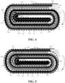
- Figs. 4 to 7 respectively show several possible schematic cross-sectional diagrams of the electrode assembly 2 according to an embodiment of the present application.
- the electrode assembly 2 shown in Figs. 4 to 7 may be several possible cross-sectional diagrams of any electrode assembly 2 shown in Fig. 3 , specifically, may be several possible cross-sectional diagrams of the main body 201 of the electrode assembly 2 shown in Fig. 3 .
- the cross-sections shown in Figs. 4 to 7 are cross-sections along the same direction, and the cross-sections are planes perpendicular to the direction of the winding axis of the electrode assembly 2.
- the electrode assembly 2 of the embodiment of the present application includes: a positive electrode plate 21, a first separator 23, a negative electrode plate 22 and a second separator 24.
- the positive electrode plate 21, the first separator 23, the negative electrode plate 22 and the second separator 24 are wound to form the electrode assembly 2.
- the first separator 23 and the second separator 24 are configured to isolate the positive electrode plate 21 from the negative electrode plate 22, and a winding start end 221 of the negative electrode plate 22, a winding start end 231 of the first separator 23 and a winding start end 241 of the second separator 24 are substantially aligned with one another.
- the electrode assembly 2 of the embodiment of the present application may be shaped according to actual applications.
- the shape of the electrode assembly 2 mainly refers to the shape of the main body 201 of the electrode assembly 2.
- the shape of the main body 201 may be a cylinder, or may be other shapes.
- the shape shown in Figs. 3 to 7 is mainly taken as an example.
- the cross-section of the main body 201 of the electrode assembly 2 is approximately oblong, that is, the cross-section of the electrode assembly 2 along a first plane is oblong.
- the first plane is perpendicular to the winding axis of the electrode assembly 2, and the main body 201 is cylindrical as a whole, but the embodiments of the present application are not limited thereto.
- the positive electrode plate 21 and the negative electrode plate 22 in the embodiments of the present application refer to parts of the main body 201 of the electrode assembly 2.
- the positive electrode plate 21 does not include the positive tab 2021
- the positive electrode plate 21 is formed by coating a positive electrode active material layer on a surface of a positive electrode current collector, the positive electrode current collector not coated with the positive electrode active material layer protrudes from the positive electrode current collector that has been coated with the positive electrode active material layer, and the positive electrode current collector not coated with the positive electrode active material layer is serves as the positive tab 2021.
- the positive electrode plate 21 is connected to the positive tab 2021.
- the negative electrode plate 22 in the embodiments of the present application does not include the negative tab 2022, that is, the negative electrode plate 22 is formed by coating a negative electrode active material layer on a surface of a negative electrode current collector, and the negative electrode current collector not coated with the negative electrode active material layer protrudes from the negative electrode current collector that has been coated with the negative electrode active material layer, and the negative electrode current collector not coated with the negative electrode active material layer serves as the negative tab 2022.
- the negative electrode plate 22 is connected to the negative tab 2022.
- no further details will be given below.
- the first separator 23 and the second separator 24 in the embodiments of the present application are both used to isolate the positive electrode plate 21 from the negative electrode plate 22, but the present application does not limit the arrangement positions and order of the first separator 23 and the second separator 24. Specifically, as shown in Figs. 4 to 7 , at any position of the electrode assembly 2, the first separator 23 and/or the second separator 24 may be arranged between the positive electrode plate 21 and the negative electrode plate 22, so that at any position of the electrode assembly 2, the positive electrode plate 21 and the negative electrode plate 22 are not in direct contact with each other, so as to avoid short circuiting.
- multiple winding start ends or multiple winding terminal ends are substantially aligned.
- substantially alignment is meant that the distance between the positions of multiple end points (e.g., end points of the multiple winding start ends, or end points of the multiple winding terminal ends) along the winding direction X of the electrode assembly 2 is less than or equal to a preset value.
- the preset value may be set to any value slightly greater than zero, in order to make the distance between the positions of the multiple end points along the winding direction X of the electrode assembly 2 approaches zero or is equal to zero.
- the winding start end 221 of the negative electrode plate 22 the winding start end 231 of the first separator 23 and the winding start end 241 of the second separator 24 being substantially aligned with one another, it is meant that the distance between the end points of every two winding start ends of the three winding start ends along the winding direction X of the electrode assembly 2 is less than or equal to a preset value, so that the distance between the end points of every two winding start ends of the three winding start ends along the winding direction X of the electrode assembly 2 is approximately equal to zero.
- the embodiments of the present application provide an electrode assembly 2.
- the electrode assembly 2 includes a positive electrode plate 21, a first separator 23, a negative electrode plate 22, and a second separator 24.
- a winding start end 221 of the negative electrode plate 22, a winding start end 231 of the first separator 23 and a winding start end 241 of the second separator 24 are substantially aligned with one another. In this way, compared with the conventional electrode assembly 100 shown in Fig.
- the negative electrode plate 22 when the electrode assembly 2 of the embodiments of the present application is initially wound, the negative electrode plate 22 can be initially wound simultaneously with the first separator 23 and the second separator 24, and it is not necessary to delay the feeding of the negative electrode plate 22 by friction, so that not only can the time interval caused by the need to delay the feeding of the negative electrode plate 22 be reduced, but the problems of deflection and folding of the initially wound head that may occur when the feeding of the negative electrode plate 22 is delayed by friction can also be avoided, thereby further improving the manufacturing efficiency of the electrode assembly 2.
- a winding start end 211 of the positive electrode plate 21 is located downstream of the winding start end 221 of the negative electrode plate 22, so as to avoid lithium plating.
- the winding start end 221 of the negative electrode plate 22 the winding start end 231 of the first separator 23 and the winding start end 241 of the second separator 24 are substantially aligned with one another, but the winding start end 211 of the positive electrode plate 21 and the winding start end 221 of the negative electrode plate 22 are not aligned with each other.
- the positive electrode plate 21 is fed with a delay, so that the winding start end 211 of the positive electrode plate 21 is located downstream of the winding start end 221 of the negative electrode plate 22, thereby avoiding lithium plating.
- downstream herein means that the winding start end 211 of the positive electrode plate 21 is behind the winding start end 221 of the negative electrode plate 22 by a certain distance along the winding direction X of the electrode assembly 2.
- winding cycle in the embodiments of the present application means that one rotation along the winding direction X of the electrode assembly 2 is one winding cycle.
- the length of the electrode plate in one winding cycle may be different. For example, taking the negative electrode plate 22 as an example, along the winding direction X of the electrode assembly 2, for a position closer to the winding axis of the electrode assembly 2, the length of the negative electrode plate 22 in one winding cycle is greater than that for a position farther away from the winding axis of the electrode assembly 2.
- the positive electrode plate 21 does not start to be wound until the negative electrode plate rotates for more than one revolution, which will cause waste of the negative electrode plate 22.
- a winding terminal end 222 of the negative electrode plate 22, a winding terminal end 232 of the first separator 23 and a winding terminal end 242 of the second separator 24 are substantially aligned with one another in the embodiments of the present application.
- the winding process of the negative electrode plate 22, the first separator 23 and the second separator 24 can be ended by simultaneously cutting the negative electrode plate 22, the first separator 23 and the second separator 24 rather than first cutting the negative electrode plate 22 and then cutting the first separator 23 and the second separator 24, thereby saving the manufacturing time and improving the manufacturing efficiency of the electrode assembly 2.
- a winding terminal end 212 of the positive electrode plate 21 is located upstream of the winding terminal end 222 of the negative electrode plate 22, so as to avoid lithium plating.
- the winding terminal end 222 of the negative electrode plate 22 the winding terminal end 232 of the first separator 23 and the winding terminal end 242 of the second separator 24 are substantially aligned with one another, but the winding terminal end 212 of the positive electrode plate 21 and the winding terminal end 222 of the negative electrode plate 22 are not aligned with each other.
- the positive electrode plate 21 Before cutting the negative electrode plate 22, the positive electrode plate 21 is first cut, and then the negative electrode plate 22, the first separator 23 and the second separator 24 are cut, so that the winding terminal end 212 of the positive electrode plate 21 is located upstream of the winding terminal end 222 of the negative electrode plate 22, so as to avoid lithium plating.
- upstream herein means that the winding terminal end 212 of the positive electrode plate 21 is located in front of the winding terminal end 222 of the negative electrode plate 22 along the winding direction X of the electrode assembly 2, and is at a certain distance ahead of the winding terminal end 222 of the negative electrode plate 22.
- the winding terminal end 212 of the positive electrode plate 21 is located upstream of the winding terminal end 222 of the negative electrode plate 22, the length by which the winding terminal end 222 of the negative electrode plate 22 exceeds the winding terminal end 211 of the positive electrode plate 21 should be reasonably set, so as to avoid waste of the negative electrode plate 22 while avoiding lithium plating.
- the energy density of the battery cell composed of the electrode assembly 2 in Figs. 4 and 5 is smaller. That is, the battery cell composed of the electrode assembly 2 shown in Figs. 6 and 7 can achieve a higher energy density.
- Figs. 8 and 9 each show a schematic cross-sectional diagram of a device 3 for preparing an electrode assembly according to an embodiment of the present application.
- the direction of the cross-section is consistent with the direction of the cross-section shown in Figs. 4 to 7 , that is, perpendicular to the winding axis of the electrode assembly 2.
- the electrode assembly 2 shown in Fig. 6 may be manufactured by the device 3 shown in Fig. 8 and using the winding and manufacturing method shown in Fig. 8 ; and the electrode assembly 2 shown in Fig. 7 may be manufactured by the device 3 shown in Fig. 9 and using the winding and manufacturing method shown in Fig. 9 .
- the electrode assemblies 2 of the embodiments of the present application can be prepared by device 3.
- the device 3 includes a winding needle, which includes a first component 31 and a second component 32.
- the cross-sectional shapes of the first component 31 and the second component 32 in the embodiments of the present application are the same.
- the cross-section of the first component 31 is semicircular
- the cross-section of the second component 32 is also semicircular.
- the two components of the winding needle in the embodiments of the present application each include a planar area and an arc-shaped area.
- the semicircular first component 31 includes a first planar area 311 and a first arc-shaped area 312.
- the semicircular second component 32 includes a second planar area 321 and a second arc-shaped area 322.
- the first planar area 311 of the first component 31 faces the second planar area 321 of the second component 32, so that the first arc-shaped area 312 and the second arc-shaped area 322 of the winding needle substantially form a complete circle, that is, the winding needle is cylindrical.
- first planar area 311 and the second planar area 321 in the embodiment of the present application are smooth and straight surfaces; and the first arc-shaped area 312 and the second arc-shaped area 322 are also smooth surfaces. Therefore, the first component 31 and the second component 32 will substantially not cause mechanical hard damage to the positive electrode plate 21 and the negative electrode plate 22 of the electrode assembly 2, so that the manufacturing yield of the electrode assembly 2 can be increased.
- the negative electrode plate 22 includes a first corner 223, a planar area 224 and a second corner 225 in sequence.
- the first corner 223 is the corner closest to the winding start end 221 of the negative electrode plate 22.
- the winding start end 221 of the negative electrode plate 22, the winding start end 231 of the first separator 23 and the winding start end 241 of the second separator 24 are substantially aligned with one another, and the negative electrode plate 22, the first separator 23 and the second separator 24 are clamped between the first planar area 311 and the second planar area 321 to facilitate the start of winding.
- the winding start end 221 of the negative electrode plate 22 generally extends beyond the first planar area 311 and the second planar area 321, or in other words, along the winding direction X of the electrode assembly 2, the clamped area of the negative electrode plate 22 has a preset distance from the winding start end 221 of the negative electrode plate 22. That is, the winding start end 221 of the negative electrode plate 22 is generally located in the first arc-shaped area 312 or in the second arc-shaped area 322.
- the winding start end 231 of the first separator 23 and the winding start end 241 of the second separator 24 are also located in the first arc-shaped area 312 or in the second arc-shaped area 322. Therefore, the negative electrode plate 22 of the electrode assembly 2 obtained by winding in the above manner includes a first corner 223, a planar area 224 and a second corner 225 which are connected to one another.
- the planar area 224 corresponds to a portion of the negative electrode plate 22 that is clamped between the first planar area 311 and the second planar area 321, and the first corner 223 is located between the winding start end 221 of the negative electrode plate 22 and the planar area 224.
- the length of a distance L1 between the winding start end 221 of the negative electrode plate 22 and the first corner 223 may be set according to actual applications.
- the distance L1 between the winding start end 221 of the negative electrode plate 22 and the first corner 223 has a value range of [3 mm, 30 mm]. That is to say, as shown in Figs.
- the distance L1 by which the winding start end 221 of the negative electrode plate 22 exceeds the first planar area 311 should not be too small, generally greater than or equal to 3 mm, to prevent the negative electrode plate 22 from being displaced, which otherwise causes lithium plating, under the clamping action of the first component 31 and the second component 32 when the distance L1 is too small.
- the distance L1 by which the winding start end 221 of the negative electrode plate 22 exceeds the first planar area 311 should also not be too large, generally less than or equal to 30 mm, to avoid waste of the negative electrode plate 22 when the distance L1 is too large, which otherwise affects the energy density of the battery cell composed of the electrode assembly 2.
- the positive electrode plate 21 in order to avoid lithium plating, is generally not clamped between the first planar area 311 and the second planar area 321, that is, the winding start end 211 of the positive electrode plate 21 is located at an arc-shaped area of an outer surface of the winding needle.
- the winding start end 211 of the positive electrode plate 21 is located in the second arc-shaped area 322 as an example.
- the winding start end 211 of the positive electrode plate 21 is located downstream of the second corner 225. In this way, the distance between the winding start end 211 of the positive electrode plate 21 and the winding start end 221 of the negative electrode plate 22 is greater than half the winding cycle, so that lithium plating can be effectively avoided.
- the length of a distance L2 between the winding start end 211 of the positive electrode plate 21 and the second corner 225 may be set according to actual applications.
- the distance L2 between the winding start end 211 of the positive electrode plate 21 and the second corner 225 has a value range of [3 mm, 30 mm]. That is to say, as shown in Figs.
- the distance L2 of the positive electrode plate 21 from the first planar area 311 should not be too small, generally greater than or equal to 3 mm, to avoid lithium plating in the area of the negative electrode plate 22 corresponding to the winding start end 211 of the positive electrode plate 21 when the distance L2 is too small.
- the distance L2 should also not be set too large, generally less than or equal to 30 mm, to avoid waste of the negative electrode plate 22 due to the too small length of the positive electrode plate21 when the distance L2 is too large, which otherwise affects the energy density of the battery cell composed of the electrode assembly 2.
- the winding start end 211 of the positive electrode plate 21 is located inside a connecting section 226 of the negative electrode plate 22.
- the connecting section 226 of the negative electrode plate 22 is at least a partial area of the negative electrode plate 22 that is connected to the second corner 225 and close to the second corner 225. Specifically, as shown in Figs.
- the first planar area 311 and the second planar area 321 clamp the negative electrode plate 21 such that the negative electrode plate 21 forms a first corner 223, a first planar area 224 and a second corner 225 which are connected to one another; and along the winding direction X of the electrode assembly 2, connected to the second corner 225 is the connecting section 226 of the negative electrode plate 22.
- the winding start end 211 of the positive electrode plate 21 is closer to the first arc-shaped plane 312 the second arc-shaped plane 322 than the connecting section 226, that is, in the radial direction of the electrode assembly 2 and outwardly from the winding axis of the electrode assembly 2, or in the radial direction of the winding needle and outwardly from the outer surface of the winding needle, the winding start end 211 of the positive electrode plate 21 is located inside the negative electrode plate 22. In this way, not only can lithium plating be avoided, but the length of the negative electrode plate 22 can also be reduced as much as possible.
- the positive electrode plate 21 is located outside the negative electrode plate 22, whereas in the electrode assembly 2 shown in Figs. 6 and 7 , the positive electrode plate 21 is located inside the negative electrode plate 22. It can be seen from the comparison that Figs. 4 to 7 can also avoid lithium plating, and along the winding direction X of the electrode assembly 2, the length of the positive electrode plate 21 is also substantially the same, but the length of the negative electrode plate 21 in Figs. 4 and 5 is greater than the length of the negative electrode plate 21 shown in Figs. 6 and 7 .
- the energy density of the battery cell composed of the electrode assembly 2 shown in Figs. 4 and 5 is less than the energy density of the battery cell composed of the electrode assembly 2 shown in Figs. 6 and 7 . That is, the battery cell using the electrode assembly 2 shown in Figs. 6 and 7 has a higher energy density.
- the first component 31 and the second component 32 clamp the negative electrode plate 22, the first separator 23 and the second separator 24, and after the positive electrode plate 21 is fed with a delay, the first component 31 and the second component 32 rotate together as a whole, so that the positive electrode plate 21, the negative electrode plate 22, the first separator 23 and the second separator 24 are wound around the first arc-shaped plane 311 and the second arc-shaped plane 321, so as to form the wound electrode assembly 2.
- the winding direction of the electrode assembly 2 is opposite to the rotation direction of the first component 31 and the second component 32.
- the overall cross-section of the first component 31 and the second component 32 in the embodiments of the present application is approximately circular, and the electrode assembly 2 correspondingly obtained by winding is also circular.
- the electrode assembly 2 correspondingly obtained by winding is also circular.
- it can be obtained by extruding a circular electrode assembly 2.
- an inactive area may be provided at the corner of the positive electrode plate 21 to avoid lithium plating.
- the positive electrode plate 21 includes a third corner 213 and an inactive area 214.
- the inactive area 214 includes the third corner 213.
- a surface of the inactive area 214 facing the winding axis of the electrode assembly 2 is provided with an insulating layer, or the positive electrode active material layer on the surface of the inactive area 214 facing the winding axis of the electrode assembly 2 fails.
- the positive electrode plate 21 cannot work normally, that is, it cannot generate lithium ions, so that it is possible to avoid lithium plating in the area of the negative electrode plate 22 corresponding to the inactive area 214. For example, it is possible to avoid lithium plating at the corresponding corner of the negative electrode plate 22.
- the arrangement of the inactive area 214 may be selected according to actual applications.
- the inactive area 214 may be provided at a corresponding position of the positive electrode plate 21, such that in the electrode assembly 2 after winding, the inactive area 214 of the positive electrode plate 21 can include a third corner 213.
- an insulating layer may be provided on the surface of the inactive area 214 facing the winding axis of the electrode assembly 2.
- an insulating material may be sprayed, or an insulating adhesive may be adhered.
- the positive electrode active material layer on the surface of the inactive area 214 facing the winding axis of the electrode assembly 2 may be deactivated, such that the positive electrode active material layer on the surface of the inactive area 214 facing the winding axis of the electrode assembly 2 fails, but the embodiments of the present application are not limited thereto.
- the third corner 213 is the corner of the positive electrode plate 21 closest to the winding axis of the electrode assembly 2.
- the corner of the positive electrode plate 21 closest to the winding axis of the electrode assembly 2 has a greater possibility of being subjected to lithium plating than the other corners. Therefore, the third corner 213 may be the corner of the positive electrode plate 21 closest to the winding axis of the electrode assembly 2, that is, the inactive area 214 is only provided at the corner of the positive electrode plate 21 closest to the winding axis of the electrode assembly 2.
- the inactive area 214 generally faces the first corner 223 of the negative electrode plate 22.
- the inactive area 214 includes the third corner 213, that is, the range of the inactive area 214 exceeds the third corner 213, and the inactive area 214 then can extend to the planar area connected to the third corner 213.
- the inactive area 214 can avoid short circuiting caused by overlap between the winding start end 221 of the negative electrode plate 22 and the positive electrode plate 21.
- the length of the inactive area 214 may be set according to actual applications.
- the length of the inactive area 214 has a value range of [10 mm, 40 mm].
- the length of the inactive area 214 should not be too small, and the position of the inactive area 214 generally includes the position of the winding start end 221 of the negative electrode plate 22.
- the electrode assembly 2 further includes a finishing adhesive 25.
- the finishing adhesive 25 is configured to fix the winding terminal end 222 of the negative electrode plate 22, the winding terminal end 232 of the first separator 23 and the winding terminal end 242 of the second separator 24.
- the finishing adhesive 25 is provided on the outermost layer, that is, the finishing adhesive 25 constitutes at least part of the outer surface of the electrode assembly 2 for fixing the electrode assembly 2 to avoid problems such as loosening and collapse of the electrode assembly 2.
- the winding terminal end 222 of the negative electrode plate 22 is located outside the winding terminal end 232 of the first separator 23 and the winding terminal end 242 of the second separator 24, and along the winding direction X of the electrode assembly 2, the finishing adhesive 25 surrounds the outermost side of the negative electrode plate 22.
- the finishing adhesive 25 surrounds the outermost side of the negative electrode plate 22.
- the winding terminal end 222 of the negative electrode plate 22, the winding terminal end 232 of the first separator 23 and the winding terminal end 242 of the second separator 24 of the electrode assembly 2 of the present application are substantially aligned with one another, that is, they can be cut at the same time, so it is possible that the winding terminal end 222 of the negative electrode plate 22 is located outside the winding terminal end 232 of the first separator 23 and the winding terminal end 242 of the second separator 24.
- the finishing adhesive 25 to surround the outermost side of the negative electrode plate 22, the negative electrode plate 22 can be protected, and the positive electrode plate 21, the first separator 23 and the second separator 24 on the inner side can also be protected, thereby increasing the structural strength and the stability of the electrode assembly 2.
- the winding direction X of the electrode assembly 2 is mainly taken as an example to define the length relationship between the positive electrode plate 21, the negative electrode plate 22, the first separator 23 and the second separator 24.
- the height direction of the electrode assembly 2 that is, the width direction of each electrode plate and each separator, may be set according to actual applications.
- the height direction of the electrode assembly 2 is perpendicular to the cross-sections as shown in Figs. 4 to 6 .
- the width of the positive electrode plate 21 is generally greater than or equal to the width of the negative electrode plate 22 to avoid lithium plating; and the width of the first separator 23 and the width of the second separator 24 are generally greater than or equal to the width of the negative electrode plate 22 to avoid short circuiting, but the embodiments of the present application are not limited thereto.
- the winding needle in the embodiments of the present application can be removed after the electrode assembly 2 is wound. Specifically, after the electrode assembly 2 is wound, the winding needle, that is, the first component 31 and the second component 32, can be removed from the electrode assembly 2 to obtain the manufactured electrode assembly 2.
- the electrode assembly 2 wound by the cylindrical winding needle including the first component 31 and the second component 32 as shown in Figs. 8 and 9 is a cylindrical electrode assembly 2.
- the cylindrical electrode assembly 2 may be deformed by hot-pressing the electrode assembly 2 from which the winding needle has been removed.
- the electrode assembly 2 may be hot-pressed to obtain the electrode assembly 2 as shown in Figs. 4 to 7 , that is, the cross-section of the electrode assembly 2 is deformed from a circular shape to an oblong shape.
- the electrode assembly 2 includes a positive electrode plate 21, a first separator 23, a negative electrode plate 22, and a second separator 24.
- a winding start end 221 of the negative electrode plate 22, a winding start end 231 of the first separator 23 and a winding start end 241 of the second separator 24 are substantially aligned with one another. In this way, compared with the conventional electrode assembly 100 shown in Fig.
- the negative electrode plate 22 when the electrode assembly 2 of the embodiments of the present application is initially wound, the negative electrode plate 22 can be initially wound simultaneously with the first separator 23 and the second separator 24, and it is not necessary to delay the feeding of the negative electrode plate 22 by friction, so that not only can the time interval caused by the need to delay the feeding of the negative electrode plate 22 be reduced, but the problems of deflection and folding of the initially wound head that may occur when the feeding of the negative electrode plate 22 is delayed by friction can also be avoided, thereby further improving the manufacturing efficiency of the electrode assembly 2.
- the electrode assembly 2 shown in Fig. 7 is taken as an example.
- the length of the negative electrode plate 22 of the electrode assembly 2 is equal to the lengths of both the first separator 23 and the second separator 24.
- the distance between the winding start end 211 of the positive electrode plate 21 and the second corner 225 is 10 mm, and the distance between the winding terminal end 212 of the positive electrode plate 21 and the winding terminal end 222 of the negative electrode plate 22 is 10 mm; and the length of the inactive area 214 of the third corner 213 of the positive electrode plate 21 is 40 mm.
- the number of layers of the positive electrode plate 21, the number of layers of the negative electrode plate 22, the number of layers of the first separator 23, the number of layers of the second separator 24 and the number of layers of the finishing adhesive 25 of the electrode assembly 2 are shown in Table 1 below. Furthermore, the thickness of a single layer of the positive electrode plate 21 is 0.1165 mm, and the thickness of a single layer of the negative electrode plate 22 is 0.1492 mm.
- the electrode assembly 100 shown in Fig. 1 is taken as an example.
- the length of the first separator 102 and the length of the second separator 104 of the electrode assembly 100 are both greater than the length of the negative electrode plate 101
- the winding start end of the positive electrode plate 103 and the winding start end of the negative electrode plate 101 are located at corners on the same side during feeding, and the distance between the winding start end of the positive electrode plate 103 and the respective corner exceeds the distance between the winding start end of the negative electrode plate 101 and the respective corner.
- An active layer of the negative electrode plate 101 on the innermost side is separated from the positive electrode plate 103 by one layer of a separator, and an active layer on the other side is separated by six layers of the separator from and corresponds to the other layer of the negative electrode plate 101; and after the negative electrode plate 101 is cut and finished, the two separators are wound with another six layers, and the length of the finishing adhesive 105 is consistent with that in the first example.
- the thickness of a single layer of the positive electrode plate 103 is 0.1168 mm
- the thickness of a single layer of the negative electrode plate 101 is 0.1496 mm.
- one layer of the positive electrode plate 21 means that along the winding direction X of the electrode assembly 2, half a winding cycle is one layer, or one layer is between two adjacent corners of the positive electrode plate 21.
- the thickness of the single layer of the first separator and the thickness of the single layer of the second separator are both 0.012 mm; the thickness of the single layer of the finishing adhesive is 0.030 mm; the total circumference of an outer wall of the winding needle used for manufacturing is 260 mm; and a positive electrode slurry has a certain proportion, and a negative electrode slurry has a certain proportion.
- Table 1 Group Number of layers of positive electrode plate Number of layers of negative electrode plate Total number of layers of first separator and second separator Number of layers of finishing adhesive PPM VED First example 41 42 84 1 6 102.03% Second example 41 42 84 2 6 101.74% Third example 40 42 96 1 4 100%
- PPM productivity of the electrode assembly, specifically the number of electrode assemblies per minute wound by each winding device
- VED represents the relative proportion of the volumetric energy density of the electrode assembly, where "VED” is a percentage relative to the third example, that is, the VED of the third example is set to 100%.
- each device only produces four electrode assemblies 100 per minute. However, if the time intervals between feedings and final cuttings of the negative electrode plate and the two separators is eliminated, the productivity can be greatly increased. For example, in the first example and the second example, each device can produce six electrode assemblies 2 per minute, and the productivity thereof can be increased by 50% compared with the third example.
- the electrode assembly 2 of the embodiments of the present application can increase both the productivity and the energy density.
- Fig. 10 shows a schematic flow chart of a method 400 for preparing an electrode assembly according to an embodiment of the present application.
- the method 400 includes: a step S410 of clamping a first separator 23, a negative electrode plate 22 and a second separator 24 by a winding needle, where the first separator 23 and the second separator 24 are configured to isolate a positive electrode plate 21 from the negative electrode plate 22, and a winding start end 221 of the negative electrode plate 22, a winding start end 231 of the first separator 23 and a winding start end 241 of the second separator 24 are substantially aligned with one another; and a step S420 of feeding the positive electrode plate 21, and winding the positive electrode plate 21, the first separator 23, the negative electrode plate 22 and the second separator 24 to form the electrode assembly 2, where along a winding direction X of the electrode assembly 2, a winding start end 221 of the positive electrode plate 21 is located downstream of the winding start end 221 of the negative electrode plate 22.
- a clamped area of the negative electrode plate 22 has a preset distance from the winding start end 221 of the negative electrode plate 22.
- the method 400 further includes: providing an inactive area 214 on the positive electrode plate 21 such that the inactive area 214 faces a portion between the clamped area of the negative electrode plate 22 and the winding start end 221 of the negative electrode plate 22.
- Providing an inactive area 214 on the positive electrode plate 21 includes: providing an insulating layer on a partial area of a surface of the positive electrode plate 21 facing the winding needle to form the inactive area 214, or performing a failure treatment on a partial area of a positive electrode active material layer on the surface of the positive electrode plate 21 facing the winding needle to form the inactive area 214.
- the length of the inactive area 214 has a value range of [10 mm, 40 mm].
- the method 400 further includes: removing the winding needle from the electrode assembly 2 after completing the winding of the electrode assembly 2.
- Fig. 11 shows a schematic block diagram of a device 500 for preparing an electrode assembly according to an embodiment of the present application.
- the device 500 includes a winding needle 510.
- the winding needle 510 is configured to clamp a first separator 23, a negative electrode plate 22 and a second separator 24.
- the first separator 23 and the second separator 24 are configured to isolate a positive electrode plate 21 from the negative electrode plate 22, and a winding start end 221 of the negative electrode plate 22, a winding start end 231 of the first separator 23 and a winding start end 241 of the second separator 24 are substantially aligned with one another.
- the winding needle 510 is further configured to feed the positive electrode plate 21, and winding the positive electrode plate 21, the first separator 23, the negative electrode plate 22 and the second separator 24 to form the electrode assembly 2.
- a winding start end 221 of the positive electrode plate 21 is located downstream of the winding start end 221 of the negative electrode plate 22.
- the winding start end 211 of the positive electrode plate 21 is located inside the negative electrode plate 22.
- a clamped area of the negative electrode plate 22 has a preset distance from the winding start end 221 of the negative electrode plate 22.
- the device 500 further includes a processing module 520.
- the processing module 520 is configured to provide an inactive area 214 on the positive electrode plate 21 such that the inactive area 214 faces a portion between the clamped area of the negative electrode plate 22 and the winding start end 221 of the negative electrode plate 22.
- the processing module 520 may be specifically configured to: provide an insulating layer on a partial area of a surface of the positive electrode plate 21 facing the winding needle to form the inactive area 214, or to perform a failure treatment on a partial area of a positive electrode active material layer on the surface of the positive electrode plate 21 facing the winding needle to form the inactive area 214.
- the length of the inactive area 214 has a value range of [10 mm, 40 mm].
- the device 500 further includes a withdrawal module for removing the winding needle from the electrode assembly 2 after completing the winding of the electrode assembly 2.
- the method 400 and the device 500 for preparing an electrode assembly according to the embodiments of the present application can be used to prepare the electrode assembly 2 according to the embodiments of the present application, and will not be described again here for the sake of brevity.
Landscapes
- Chemical & Material Sciences (AREA)
- Chemical Kinetics & Catalysis (AREA)
- Electrochemistry (AREA)
- General Chemical & Material Sciences (AREA)
- Engineering & Computer Science (AREA)
- Manufacturing & Machinery (AREA)
- Materials Engineering (AREA)
- Secondary Cells (AREA)
- Battery Electrode And Active Subsutance (AREA)
Abstract
Description
- The present application claims the priority of
Chinese Patent Application No. 202210716973.X filed on June 23, 2022 - The present application relates to the technical field of batteries, and in particular, to an electrode assembly, a battery cell, a battery and an electrical device.
- Energy conservation and emission reduction are key to sustainable development of the automobile industry. In this case, electric vehicles have become an important part of the sustainable development of the automobile industry because of their advantages of energy saving and environmental friendliness. For the electric vehicles, the battery technology is an important factor related to their development.
- The overall production process of the battery is long and complicated, including a series of procedures such as coating, plate production, winding, assembling, laser welding, and liquid injection. The manufacturing process of an electrode assembly inside a battery cell is particularly important, which will directly affect the manufacturing efficiency and performance of the battery cell. Therefore, how to improve the manufacturing efficiency of the electrode assembly is a technical problem to be solved urgently.
- Embodiments of the present application provide an electrode assembly, a battery cell, a battery and an electrical device, which improve the manufacturing efficiency of the electrode assembly.
- In a first aspect, provided is an electrode assembly, including: a positive electrode plate, a first separator, a negative electrode plate and a second separator, the positive electrode plate, the first separator, the negative electrode plate and the second separator being wound to form the electrode assembly, wherein the first separator and the second separator are configured to isolate the positive electrode plate from the negative electrode plate, and a winding start end of the negative electrode plate, a winding start end of the first separator and a winding start end of the second separator are substantially aligned with one another.
- Therefore, the embodiments of the present application provide an electrode assembly, which includes a positive electrode plate, a first separator, a negative electrode plate, and a second separator, wherein a winding start end of the negative electrode plate, a winding start end of the first separator and a winding start end of the second separator are substantially aligned with one another. In this way, compared with the conventional electrode assembly, when the electrode assembly of the embodiments of the present application is initially wound, the negative electrode plate can be initially wound simultaneously with the first separator and the second separator, and it is not necessary to delay the feeding of the negative electrode plate by friction, so that not only can the time interval caused by the need to delay the feeding of the negative electrode plate be reduced, but the problems of deflection and folding of the initially wound head that may occur when the feeding of the negative electrode plate is delayed by friction can also be avoided, thereby further improving the manufacturing efficiency of the electrode assembly.
- In some embodiments, along a winding direction of the electrode assembly, a winding start end of the positive electrode plate is located downstream of the winding start end of the negative electrode plate, so as to avoid lithium plating.
- In some embodiments, along the winding direction of the electrode assembly, a distance between the winding start end of the positive electrode plate and the winding start end of the negative electrode plate is greater than or equal to half a winding cycle and less than one winding cycle.
- In this way, lithium plating can be effectively avoided, waste caused by too long negative electrode plates can be avoided, and the energy density of the battery cell where the electrode assembly is located can also be increased.
- In some embodiments, a winding terminal end of the negative electrode plate, a winding terminal end of the first separator and a winding terminal end of the second separator are substantially aligned with one another.
- When winding the electrode assembly, the winding process of the negative electrode plate, the first separator and the second separator can be ended by simultaneously cutting the negative electrode plate, the first separator and the second separator rather than first cutting the negative electrode plate and then cutting the first separator and the second separator, thereby saving the manufacturing time and improving the manufacturing efficiency of the electrode assembly.
- In some embodiments, along the winding direction of the electrode assembly, a winding terminal end of the positive electrode plate is located upstream of the winding terminal end of the negative electrode plate, so as to avoid lithium plating.
- In some embodiments, along the winding direction of the electrode assembly, the negative electrode plate includes a first corner, a planar area and a second corner in sequence, the first corner being the corner closest to the winding start end of the negative electrode plate. In this way, during the manufacturing of the electrode assembly, a winding needle can stably clamp and secure the negative electrode plate, the first separator and the second separator, thereby preventing the negative electrode plate from being displaced, which otherwise causes lithium plating.
- In some embodiments, along the winding direction of the electrode assembly, a distance between the winding start end of the negative electrode plate and the first corner has a value range of [3 mm, 30 mm].
- The distance between the winding start end of the negative electrode plate and the first corner should not be too small, to prevent the negative electrode plate from being displaced, which otherwise causes lithium plating, under the clamping action of the winding needle when the distance is too small. On the contrary, the distance between the winding start end of the negative electrode plate and the first corner should also not be too large, to avoid waste of the negative electrode plate when the distance is too large, which otherwise affects the energy density of the battery cell composed of the electrode assembly.
- In some embodiments, along the winding direction of the electrode assembly, the winding start end of the positive electrode plate is located downstream of the second corner.
- In this way, the distance between the winding start end of the positive electrode plate and the winding start end of the negative electrode plate is greater than half the winding cycle, so that lithium plating can be effectively avoided.
- In some embodiments, along the winding direction of the electrode assembly, a distance between the winding start end of the positive electrode plate and the second corner has a value range of [3 mm, 30 mm].
- The distance between the winding start end of the positive electrode plate and the second corner should not be too small, to avoid lithium plating in the area of the negative electrode plate corresponding to the winding start end of the positive electrode plate when the distance is too small. On the contrary, the distance between the winding start end of the positive electrode plate and the second corner should also not be set too large, to avoid that when the distance is too large, the length of the positive electrode plate is too small, resulting in waste of the negative electrode plate, which otherwise affects the energy density of the battery cell composed of the electrode assembly.
- In some embodiments, in a radial direction of the electrode assembly and outwardly from a winding axis of the electrode assembly, the winding start end of the positive electrode plate is located inside a connecting section of the negative electrode plate, wherein the connecting section of the negative electrode plate is at least a partial area of the negative electrode plate that is connected to the second corner and close to the second corner. Not only can lithium plating be avoided, but the length of the negative electrode plate can also be reduced as much as possible.
- In some embodiments, the positive electrode plate includes a third corner and an inactive area, the inactive area including the third corner, wherein a surface of the inactive area facing the winding axis of the electrode assembly is provided with an insulating layer, or a positive electrode active material layer on the surface of the inactive area facing the winding axis of the electrode assembly fails.
- In this way, within the range of the inactive area, the positive electrode plate cannot work normally, for example, it cannot generate lithium ions, so that it is possible to avoid lithium plating in the area of the negative electrode plate corresponding to the inactive area. For example, it is possible to avoid lithium plating at the corresponding corner of the negative electrode plate.
- In some embodiments, along the winding direction of the electrode assembly, the third corner is the corner of the positive electrode plate closest to the winding axis of the electrode assembly.
- The corner of the positive electrode plate closest to the winding axis of the electrode assembly has a greater possibility of being subjected to lithium plating than the other corners. Therefore, the third corner may be the corner of the positive electrode plate closest to the winding axis of the electrode assembly, that is, the inactive area is only provided at the corner of the positive electrode plate closest to the winding axis of the electrode assembly, so that not only can lithium plating be avoided, but unnecessary waste of the electrode plate can also be avoided. Secondly, the range of the inactive area exceeds the third corner, that is, the inactive area can extend to the planar area connected to the third corner. In this way, if the first separator or the second separator at the winding start end of the negative electrode plate that is closer to the third corner shrinks, resulting in that a local area of the negative electrode plate is exposed, for example, the winding start end of the negative electrode plate may be exposed, then the inactive area can avoid short circuiting caused by overlap between the winding start end of the negative electrode plate and the positive electrode plate.
- In some embodiments, along the winding direction of the electrode assembly, the length of the inactive area has a value range of [10 mm, 40 mm]. On the one hand, setting the length to be too long is avoided, which would result in waste of the positive electrode plate and the negative electrode plate, thereby reducing the energy density of the battery cell composed of the electrode assembly; on the other hand, setting the length to be too small is avoided, such that after the winding start end of the first separator or the winding start end of the second separator shrinks, short circuiting is caused between the exposed winding start end of the negative electrode plate and the positive electrode plate after overlapping each other.
- In some embodiments, the electrode assembly further includes: a finishing adhesive configured to fix the winding terminal end of the negative electrode plate, the winding terminal end of the first separator and the winding terminal end of the second separator. The finishing adhesive is configured to fix the electrode assembly to avoid problems such as loosening and collapse of the electrode assembly.
- In some embodiments, in the radial direction of the electrode assembly and outwardly from the winding axis of the electrode assembly, the winding terminal end of the negative electrode plate is located outside the winding terminal end of the first separator and the winding terminal end of the second separator, and along the winding direction of the electrode assembly, the finishing adhesive surrounds the outermost side of the negative electrode plate.
- By arranging the finishing adhesive to surround the outermost side of the negative electrode plate, the negative electrode plate can be protected, and the positive electrode plate, the first separator and the second separator on the inner side can also be protected, thereby increasing the structural strength and the stability of the electrode assembly.
- In some embodiments, the electrode assembly has an oblong cross-section along a first plane which is perpendicular to the winding axis of the electrode assembly.
- In a second aspect, provided is a battery cell, including: an electrode assembly in the first aspect or according to any one of the embodiments in the first aspect.
- In a third aspect, provided is a battery, including: a plurality of battery cells, each electrode cell including an electrode assembly in the first aspect or according to any one of the embodiments in the first aspect.
- In a fourth aspect, provided is an electrical device, including: a battery, including an electrode assembly in the first aspect or according to any one of the embodiments in the first aspect.
- In some embodiments, the electrical device is a vehicle, a ship or a spacecraft.
- In a fifth aspect, provided is a method for preparing an electrode assembly, the method including: clamping a first separator, a negative electrode plate and a second separator by a winding needle, wherein the first separator and the second separator are configured to isolate a positive electrode plate from the negative electrode plate, and a winding start end of the negative electrode plate, a winding start end of the first separator and a winding start end of the second separator are substantially aligned with one another; and feeding the positive electrode plate, and winding the positive electrode plate, the first separator, the negative electrode plate and the second separator to form the electrode assembly, wherein along a winding direction of the electrode assembly, a winding start end of the positive electrode plate is located downstream of the winding start end of the negative electrode plate.
- In a sixth aspect, provided is a device for preparing an electrode assembly, the device including modules for implementing the method in the foregoing fifth aspect.
-
-
Fig. 1 is a schematic cross-sectional diagram of a conventional electrode assembly; -
Fig. 2 is a schematic structural diagram of a vehicle disclosed in an embodiment of the present application; -
Fig. 3 is a schematic structural diagram of an electrode assembly disclosed in an embodiment of the present application; -
Figs. 4 to 7 are several schematic cross-sectional diagrams of an electrode assembly disclosed in an embodiment of the present application; -
Figs. 8 and 9 are several schematic cross-sectional diagrams of a device for preparing an electrode assembly disclosed in an embodiment of the present application; -
Fig. 10 is a schematic flow chart of a method for preparing an electrode assembly disclosed in an embodiment of the present application; and -
Fig. 11 is a schematic block diagram of a device for preparing an electrode assembly disclosed in an embodiment of the present application. - In the accompanying drawings, the figures are not necessarily drawn to scale.
- Technical solutions in the embodiments of the present application will be described below with reference to the accompanying drawings.
- In order to make the objects, technical solutions and advantages of embodiments of the present application clearer, the technical solutions in the embodiments of the present application will be clearly described below with reference to the drawings for the embodiments of the present application. Apparently, the described embodiments are some of, rather than all of, the embodiments of the present application. All the other embodiments obtained by a person of ordinary skill in the art based on the embodiments of the present application without any creative effort shall fall within the scope of protection of the present application.
- Unless otherwise defined, all technical and scientific terms used in the present application have the same meanings as those commonly understood by those skilled in the art to which the present application belongs. The terms used in the specification of the present application are merely for the purpose of describing specific embodiments, but are not intended to limit the present application. The terms "comprising" and "having" and any variations thereof in the specification and the claims of the present application as well as the foregoing description of the drawings are intended to cover non-exclusive inclusions. The terms "first", "second" and the like in the specification and the claims of the present application as well as the above drawings are used to distinguish different objects, rather than to describe a specific order or primary-secondary relationship.
- The phrase "embodiment" referred to in the present application means that the descriptions of specific features, structures, and characteristics in combination with the embodiment are included in at least one embodiment of the present application. The appearance of this phrase in various places in the specification does not necessarily refer to the same embodiment, nor is it a separate or alternative embodiment that is mutually exclusive with other embodiments. It is understood explicitly and implicitly by those skilled in the art that the embodiments described in the present application can be combined with other embodiments.
- In the description of the present application, it should be noted that the terms "mounting", "connecting", "connection" and "attachment" should be understood in a broad sense, unless otherwise explicitly specified or defined, for example, it may be a fixed connection, a detachable connection or an integrated connection; and may be a direct connection or an indirect connection through an intermediate medium, or may be a communication between the interior of two elements. For those of ordinary skill in the art, the specific meanings of the above terms in the present application can be understood according to specific situations.
- In the present application, the term "and/or" is only an association relation describing associated obj ects, which means that there may be three relations, for example, A and/or B may represent three situations: A exists alone, both A and B exist, and B exists alone. In addition, the character "/" in the present application generally means that the associated objects before and after it are in an "or" relationship.
- In the embodiments of the present application, the same reference signs denote the same components, and for the sake of brevity, detailed descriptions of the same components are omitted in different embodiments. It should be understood that the thickness, length, width and other dimensions of the various components in the embodiments of the present application shown in the drawings, as well as the overall thickness, length, width and other dimensions of an integrated apparatus, are for illustrative purposes only, and should not constitute any limitation to the present application.
- In the present application, "a plurality of' means two or more (including two), similarly, "a plurality of groups" means two or more groups (including two groups), and "a plurality of sheets" means two or more sheets (including two sheets).
- In the present application, battery cells may include lithium-ion secondary batteries, lithium-ion primary batteries, lithium-sulfur batteries, sodium/lithium-ion batteries, sodium-ion batteries or magnesium-ion batteries, etc., which are not limited by the embodiments of the present application. The battery cell may be in a cylindrical shape, a flat shape, a cuboid shape or another shape, which is also not limited in the embodiments of the present application. The battery cells are generally classified into three types depending on the way of package: cylindrical battery cells, prismatic battery cells and pouch battery cells, which are also not limited in the embodiments of the present application.
- The battery mentioned in the embodiments of the present application refers to a single physical module including one or more battery cells to provide a higher voltage and capacity. For example, the battery mentioned in the present application may include a battery module or a battery pack, etc. The battery generally includes a box for packaging one or more battery cells. The box can prevent liquid or other foreign matters from affecting charging or discharging of the battery cells.
- The battery cell includes an electrode assembly and an electrolyte solution, the electrode assembly being composed of a positive electrode plate, a negative electrode plate and a separator. The battery cell operates mainly relying on the movement of metal ions between the positive electrode plate and the negative electrode plate. The positive electrode plate includes a positive electrode current collector and a positive electrode active material layer, a surface of the positive electrode current collector is coated with the positive electrode active material layer, the positive electrode current collector not coated with the positive electrode active material layer protrudes from the positive electrode current collector already coated with the positive electrode active material layer, and the positive electrode current collector not coated with the positive electrode active material layer is used as a positive tab. Taking a lithium-ion battery as an example, the material of the positive electrode current collector may be aluminum, and the positive electrode active material may be lithium cobalt oxide, lithium iron phosphate, ternary lithium, lithium manganate, or the like. The negative electrode plate includes a negative electrode current collector and a negative electrode active material layer, a surface of the negative electrode current collector is coated with the negative electrode active material layer, the negative electrode current collector not coated with the negative electrode active material layer protrudes from the negative electrode current collector already coated with the negative electrode active material layer, and the negative electrode current collector not coated with the negative electrode active material layer is used as a negative tab. The material of the negative electrode current collector may be copper, and the negative electrode active material may be carbon, silicon, or the like. In order to ensure that no fusing occurs when a large current passes, there are a plurality of positive tabs which are stacked together, and there are a plurality of negative tabs which are stacked together. The separator may be polypropylene (PP), polyethylene (PE), etc. In addition, the electrode assembly may have a wound structure or a stacked structure, but the embodiments of the present application are not limited thereto.
- For an electrode assembly of a wound structure, the conventional manufacturing method usually has many disadvantages.
Fig. 1 shows a schematic cross-sectional diagram of aconventional electrode assembly 100 of a wound structure. The cross-section is a cross-section perpendicular to the direction of a winding axis of theelectrode assembly 100. As shown inFig. 1 , theconventional electrode assembly 100 includes anegative electrode plate 101, afirst separator 102, apositive electrode plate 103 and asecond separator 104. Thefirst separator 102 and thesecond separator 104 are configured to isolate thepositive electrode plate 103 from thenegative electrode plate 101. Optionally, theelectrode assembly 100 may further include a finishing adhesive 105. The finishing adhesive 105 is the outermost layer of theelectrode assembly 100, for protecting its internal components. - As shown in
Fig. 1 , when theelectrode assembly 100 is wound, a winding start end of thefirst separator 102 and a winding start end of thesecond separator 104 may be clamped by a clamping apparatus. The winding start end of thefirst separator 102 and the winding start end of thesecond separator 104 are substantially aligned with each other. After initially winding to a certain length, thenegative electrode plate 101 and thepositive electrode plate 103 of a preset length are respectively brought in by the friction of thefirst separator 102 and thesecond separator 104 for winding. After winding, theelectrode assembly 100 is obtained. - This manufacturing method requires the winding of the
positive electrode plate 103 and thenegative electrode plate 101 respectively caused by the friction of thefirst separator 102 and thesecond separator 104, so the initial winding speed and acceleration should not be too large, otherwise the winding efficiency will be affected. A time interval between the feeding of thepositive electrode plate 103 and the feeding of thenegative electrode plate 101 and a time interval between final cuttings thereof will also increase the winding time of the electrode assembly, thereby affecting the winding efficiency of the electrode assembly. - Therefore, the embodiments of the present application provide an electrode assembly, which includes a positive electrode plate, a first separator, a negative electrode plate, and a second separator, wherein a winding start end of the negative electrode plate, a winding start end of the first separator and a winding start end of the second separator are substantially aligned with one another. In this way, compared with the
conventional electrode assembly 100 shown inFig. 1 , when the electrode assembly of the embodiments of the present application is initially wound, the negative electrode plate can be initially wound simultaneously with the first separator and the second separator, and it is not necessary to delay the feeding of the negative electrode plate by friction, so that not only can the time interval caused by the need to delay the feeding of the negative electrode plate be reduced, but the problems of deflection and folding of the initially wound head that may occur when the feeding of the negative electrode plate is delayed by friction can also be avoided, thereby further improving the manufacturing efficiency of the electrode assembly. - The technical solutions described in the embodiments of the present application are applicable to various electrical devices using batteries.
- The electrical device may be, but not limited to, a vehicle, a mobile phone, a portable device, a laptop, a ship, a spacecraft, an electric toy, an electric tool, and so on. The vehicle may be a fuel vehicle, a gas vehicle or a new energy vehicle. The new energy vehicle may be an all-electric vehicle, a hybrid electric vehicle, an extended-range vehicle, or the like. The spacecraft includes airplanes, rockets, space shuttles, spaceships, and the like. The electric toy includes fixed or mobile electric toys, such as game consoles, electric car toys, electric ship toys and electric aircraft toys. The electric tool includes metal cutting electric tools, grinding electric tools, assembly electric tools and railway electric tools, such as electric drills, electric grinders, electric wrenches, electric screwdrivers, electric hammers, impact drills, concrete vibrators and electric planers. The electrical device is not specially limited in the embodiments of the present application.
- In the following embodiments, for convenience of description, the electrical device being a vehicle is taken as an example for illustration.
- For example,
Fig. 2 is a schematic structural diagram of avehicle 1 according to an embodiment of the present application. Thevehicle 1 may be a fuel vehicle, a gas vehicle or a new energy vehicle. The new energy vehicle may be an all-electric vehicle, a hybrid vehicle or an extended-range vehicle, or the like. Amotor 40, acontroller 30 and abattery 10 may be provided inside thevehicle 1, and thecontroller 30 is configured to control thebattery 10 to supply power to themotor 40. For example, thebattery 10 may be arranged at the bottom or the head or the tail of thevehicle 1. Thebattery 10 may be configured to supply power to thevehicle 1, for example, thebattery 10 may be used as an operating power source of thevehicle 1, which is used for a circuit system of thevehicle 1, for example, for operation power requirements of thevehicle 1 during starting, navigation and running. In another embodiment of the present application, thebattery 10 can be used not only as an operation power supply of thevehicle 1, but also as a driving power supply of thevehicle 1, replacing or partially replacing fuel or natural gas to provide driving power for thevehicle 1. - The
battery 10 may include a box, and the inside of the box is a hollow structure. The hollow structure may be configured to receive a plurality of battery cells. Depending on different power requirements, the number of battery cells in thebattery 10 may be set to any value. A plurality of battery cells may be in series, parallel or series-parallel connection to achieve a larger capacity or power. Since there may be many battery cells included in eachbattery 10, the battery cells may be arranged in groups for convenience of installation, and each group of battery cells constitute a battery module. The number of battery cells included in the battery module is not limited, and may be set according to requirements, and these battery modules may be in series, parallel or series-parallel connection. - Optionally, the
battery 10 may further include other structures, which will not be described in detail herein. For example, thebattery 10 may further include a bus component. The bus component is configured to implement the electrical connection between the plurality of battery cells, such as parallel connection, series connection or series-parallel connection. Specifically, the bus component may implement the electrical connection between the battery cells by connecting electrode terminals of the battery cells. Further, the bus component may be fixed to the electrode terminals of the battery cells by welding. Electric energy of the plurality of battery cells may be further led out through an electrically conductive mechanism penetrating the box. - The battery cell in the embodiments of the present application may include an outer shell and an inner electrode assembly. The shell may be of a hollow structure, which is configured to receive the electrode assembly. A battery cell may be provided with one or more electrode assemblies according to the actual application. The electrode assembly is a component of a battery cell where an electrochemical reaction occurs. The electrode assembly may be a cylinder, a cuboid, etc., and the shell of the battery cell may be correspondingly shaped according to the shape of the electrode assembly.
- For example,
Fig. 3 shows a schematic structural diagram of anelectrode assembly 2 according to an embodiment of the present application. InFig. 3 , twoelectrode assemblies 2 are taken as an example. As shown inFig. 3 , theelectrode assembly 2 includestabs 202 and a main body 201 connected to each other. The main body 201 includes a positive electrode plate and a negative electrode plate, and thetabs 202 of theelectrode assembly 2 may include apositive tab 2021 and anegative tab 2022. Specifically, the main body 201 may be formed by stacking or winding the positive electrode plate coated with a positive electrode active material layer and the negative electrode plate coated with a negative electrode active material layer; and thepositive tab 2021 may be formed by stacking parts that protrude from the positive electrode plate and are not coated with the positive electrode active material layer, and thenegative tab 2022 may be formed by stacking parts that protrude from the negative electrode plate and not coated with the negative electrode active material layer. - Optionally, for a plurality of
electrode assemblies 2 included in the battery cell, thetabs 202 of the plurality ofelectrode assemblies 2 may be connected to each other. As shown inFig. 3 , thepositive tabs 2021 of the twoelectrode assemblies 2 may be electrically connected to each other, and thenegative tabs 2021 of the twoelectrode assemblies 2 may also be electrically connected to each other, so that the plurality ofelectrode assemblies 2 correspondingly include onepositive tab 2021 and onenegative tab 2022, but the embodiments of the present application are not limited thereto. - The battery cell is further provided with electrode terminals, which are configured for electrical connection with the
electrode assembly 2 to output electric energy from the battery cell. The electrode terminals may include a positive electrode terminal and a negative electrode terminal. The positive electrode terminal is configured for electrical connection with thepositive tab 2021, and the negative electrode terminal is configured for electrical connection with thenegative tab 2022. The positive electrode terminal may be connected directly or indirectly to thepositive tab 2021, and the negative electrode terminal may be connected directly or indirectly to thenegative tab 2022. Illustratively, the positive electrode terminal is electrically connected to thepositive tab 2021 via a connecting member, and the negative electrode terminal is electrically connected to thenegative tab 2022 via a connecting member. - The
electrode assembly 2 of the embodiments of the present application will be described in detail below with reference to the accompanying drawings.Figs. 4 to 7 respectively show several possible schematic cross-sectional diagrams of theelectrode assembly 2 according to an embodiment of the present application. For example, theelectrode assembly 2 shown inFigs. 4 to 7 may be several possible cross-sectional diagrams of anyelectrode assembly 2 shown inFig. 3 , specifically, may be several possible cross-sectional diagrams of the main body 201 of theelectrode assembly 2 shown inFig. 3 . The cross-sections shown inFigs. 4 to 7 are cross-sections along the same direction, and the cross-sections are planes perpendicular to the direction of the winding axis of theelectrode assembly 2. - As shown in
Figs. 4 to 7 , theelectrode assembly 2 of the embodiment of the present application includes: apositive electrode plate 21, afirst separator 23, anegative electrode plate 22 and asecond separator 24. Thepositive electrode plate 21, thefirst separator 23, thenegative electrode plate 22 and thesecond separator 24 are wound to form theelectrode assembly 2. Thefirst separator 23 and thesecond separator 24 are configured to isolate thepositive electrode plate 21 from thenegative electrode plate 22, and a winding start end 221 of thenegative electrode plate 22, a winding start end 231 of thefirst separator 23 and a winding start end 241 of thesecond separator 24 are substantially aligned with one another. - Optionally, the
electrode assembly 2 of the embodiment of the present application may be shaped according to actual applications. Specifically, the shape of theelectrode assembly 2 mainly refers to the shape of the main body 201 of theelectrode assembly 2. For example, the shape of the main body 201 may be a cylinder, or may be other shapes. For the convenience of description, in the embodiments of the present application, the shape shown inFigs. 3 to 7 is mainly taken as an example. The cross-section of the main body 201 of theelectrode assembly 2 is approximately oblong, that is, the cross-section of theelectrode assembly 2 along a first plane is oblong. The first plane is perpendicular to the winding axis of theelectrode assembly 2, and the main body 201 is cylindrical as a whole, but the embodiments of the present application are not limited thereto. - It should be understood that the
positive electrode plate 21 and thenegative electrode plate 22 in the embodiments of the present application refer to parts of the main body 201 of theelectrode assembly 2. Specifically, thepositive electrode plate 21 does not include thepositive tab 2021, thepositive electrode plate 21 is formed by coating a positive electrode active material layer on a surface of a positive electrode current collector, the positive electrode current collector not coated with the positive electrode active material layer protrudes from the positive electrode current collector that has been coated with the positive electrode active material layer, and the positive electrode current collector not coated with the positive electrode active material layer is serves as thepositive tab 2021. Thepositive electrode plate 21 is connected to thepositive tab 2021. Similarly, thenegative electrode plate 22 in the embodiments of the present application does not include thenegative tab 2022, that is, thenegative electrode plate 22 is formed by coating a negative electrode active material layer on a surface of a negative electrode current collector, and the negative electrode current collector not coated with the negative electrode active material layer protrudes from the negative electrode current collector that has been coated with the negative electrode active material layer, and the negative electrode current collector not coated with the negative electrode active material layer serves as thenegative tab 2022. Thenegative electrode plate 22 is connected to thenegative tab 2022. For the sake of brevity, no further details will be given below. - The
first separator 23 and thesecond separator 24 in the embodiments of the present application are both used to isolate thepositive electrode plate 21 from thenegative electrode plate 22, but the present application does not limit the arrangement positions and order of thefirst separator 23 and thesecond separator 24. Specifically, as shown inFigs. 4 to 7 , at any position of theelectrode assembly 2, thefirst separator 23 and/or thesecond separator 24 may be arranged between thepositive electrode plate 21 and thenegative electrode plate 22, so that at any position of theelectrode assembly 2, thepositive electrode plate 21 and thenegative electrode plate 22 are not in direct contact with each other, so as to avoid short circuiting. - It should be understood that, taking into account the influence of manufacturing errors and other factors, in the embodiments of the present application, multiple winding start ends or multiple winding terminal ends are substantially aligned. Specifically, the term "substantial alignment" is meant that the distance between the positions of multiple end points (e.g., end points of the multiple winding start ends, or end points of the multiple winding terminal ends) along the winding direction X of the
electrode assembly 2 is less than or equal to a preset value. The preset value may be set to any value slightly greater than zero, in order to make the distance between the positions of the multiple end points along the winding direction X of theelectrode assembly 2 approaches zero or is equal to zero. For example, by the winding start end 221 of thenegative electrode plate 22, the winding start end 231 of thefirst separator 23 and the winding start end 241 of thesecond separator 24 being substantially aligned with one another, it is meant that the distance between the end points of every two winding start ends of the three winding start ends along the winding direction X of theelectrode assembly 2 is less than or equal to a preset value, so that the distance between the end points of every two winding start ends of the three winding start ends along the winding direction X of theelectrode assembly 2 is approximately equal to zero. - Therefore, the embodiments of the present application provide an
electrode assembly 2. Theelectrode assembly 2 includes apositive electrode plate 21, afirst separator 23, anegative electrode plate 22, and asecond separator 24. A winding start end 221 of thenegative electrode plate 22, a winding start end 231 of thefirst separator 23 and a winding start end 241 of thesecond separator 24 are substantially aligned with one another. In this way, compared with theconventional electrode assembly 100 shown inFig. 1 , when theelectrode assembly 2 of the embodiments of the present application is initially wound, thenegative electrode plate 22 can be initially wound simultaneously with thefirst separator 23 and thesecond separator 24, and it is not necessary to delay the feeding of thenegative electrode plate 22 by friction, so that not only can the time interval caused by the need to delay the feeding of thenegative electrode plate 22 be reduced, but the problems of deflection and folding of the initially wound head that may occur when the feeding of thenegative electrode plate 22 is delayed by friction can also be avoided, thereby further improving the manufacturing efficiency of theelectrode assembly 2. - Optionally, as shown in
Figs. 4 to 7 , along the winding direction X of theelectrode assembly 2, a winding start end 211 of thepositive electrode plate 21 is located downstream of the winding start end 221 of thenegative electrode plate 22, so as to avoid lithium plating. Specifically, along the winding direction X of theelectrode assembly 2, the winding start end 221 of thenegative electrode plate 22, the winding start end 231 of thefirst separator 23 and the winding start end 241 of thesecond separator 24 are substantially aligned with one another, but the winding start end 211 of thepositive electrode plate 21 and the winding start end 221 of thenegative electrode plate 22 are not aligned with each other. After thenegative electrode plate 22, thefirst separator 23 and thesecond separator 24 are initially wound for a certain distance, thepositive electrode plate 21 is fed with a delay, so that the winding start end 211 of thepositive electrode plate 21 is located downstream of the winding start end 221 of thenegative electrode plate 22, thereby avoiding lithium plating. It should be understood that the term "downstream" herein means that the winding start end 211 of thepositive electrode plate 21 is behind the winding start end 221 of thenegative electrode plate 22 by a certain distance along the winding direction X of theelectrode assembly 2. - It should be understood that where along the winding direction X of the
electrode assembly 2, the winding start end 211 of thepositive electrode plate 21 is located downstream of the winding start end 221 of thenegative electrode plate 22, the specific position of the winding start end 211 of thepositive electrode plate 21 should be set appropriately in order to avoid waste. Specifically, as shown inFigs. 4 to 7 , along the winding direction X of theelectrode assembly 2, a distance between the winding start end 211 of thepositive electrode plate 21 and the winding start end 221 of thenegative electrode plate 22 is greater than or equal to half a winding cycle and less than one winding cycle. In this way, lithium plating can be effectively avoided, waste caused by too longnegative electrode plates 22 can be avoided, and the energy density of the battery cell where theelectrode assembly 2 is located can also be increased. - It should be understood that the term "winding cycle" in the embodiments of the present application means that one rotation along the winding direction X of the
electrode assembly 2 is one winding cycle. In addition, for different positions of theelectrode assembly 2, the length of the electrode plate in one winding cycle may be different. For example, taking thenegative electrode plate 22 as an example, along the winding direction X of theelectrode assembly 2, for a position closer to the winding axis of theelectrode assembly 2, the length of thenegative electrode plate 22 in one winding cycle is greater than that for a position farther away from the winding axis of theelectrode assembly 2. In the embodiments of the present application, if the distance between the winding start end 211 of thepositive electrode plate 21 and the winding start end 221 of thenegative electrode plate 22 is greater than one winding cycle, that is, after thenegative electrode plate 22 starts to be wound, thepositive electrode plate 21 does not start to be wound until the negative electrode plate rotates for more than one revolution, which will cause waste of thenegative electrode plate 22. - In the embodiments of the present application, correspondingly to the winding start ends, as shown in
Figs. 4 to 7 , a windingterminal end 222 of thenegative electrode plate 22, a windingterminal end 232 of thefirst separator 23 and a windingterminal end 242 of thesecond separator 24 are substantially aligned with one another in the embodiments of the present application. When winding theelectrode assembly 2, the winding process of thenegative electrode plate 22, thefirst separator 23 and thesecond separator 24 can be ended by simultaneously cutting thenegative electrode plate 22, thefirst separator 23 and thesecond separator 24 rather than first cutting thenegative electrode plate 22 and then cutting thefirst separator 23 and thesecond separator 24, thereby saving the manufacturing time and improving the manufacturing efficiency of theelectrode assembly 2. - Optionally, as shown in
Figs. 4 to 7 , along the winding direction X of theelectrode assembly 2, a windingterminal end 212 of thepositive electrode plate 21 is located upstream of the windingterminal end 222 of thenegative electrode plate 22, so as to avoid lithium plating. Specifically, along the winding direction X of theelectrode assembly 2, the windingterminal end 222 of thenegative electrode plate 22, the windingterminal end 232 of thefirst separator 23 and the windingterminal end 242 of thesecond separator 24 are substantially aligned with one another, but the windingterminal end 212 of thepositive electrode plate 21 and the windingterminal end 222 of thenegative electrode plate 22 are not aligned with each other. Before cutting thenegative electrode plate 22, thepositive electrode plate 21 is first cut, and then thenegative electrode plate 22, thefirst separator 23 and thesecond separator 24 are cut, so that the windingterminal end 212 of thepositive electrode plate 21 is located upstream of the windingterminal end 222 of thenegative electrode plate 22, so as to avoid lithium plating. It should be understood that the term "upstream" herein means that the windingterminal end 212 of thepositive electrode plate 21 is located in front of the windingterminal end 222 of thenegative electrode plate 22 along the winding direction X of theelectrode assembly 2, and is at a certain distance ahead of the windingterminal end 222 of thenegative electrode plate 22. - It should be understood that where along the winding direction X of the
electrode assembly 2, the windingterminal end 212 of thepositive electrode plate 21 is located upstream of the windingterminal end 222 of thenegative electrode plate 22, the length by which the windingterminal end 222 of thenegative electrode plate 22 exceeds the windingterminal end 211 of thepositive electrode plate 21 should be reasonably set, so as to avoid waste of thenegative electrode plate 22 while avoiding lithium plating. - In the embodiments of the present application, by adjusting the relative positions of the
positive electrode plate 21, thenegative electrode plate 22, thefirst separator 23 and thesecond separator 24, different winding methods can be used to obtaindifferent electrode assemblies 2. For example, among the fourelectrode assemblies 2 shown inFigs. 4 to 7 , the relative positions of thepositive electrode plate 21, thenegative electrode plate 22, thefirst separator 23 and thesecond separator 24 are slightly different, and the corresponding forms of theelectrode assemblies 2 are also different. Moreover, based on a comparison ofFigs. 4 to 7 , it can be seen that where lithium plating can likewise be avoided, along the winding direction X of theelectrode assembly 2, the length difference between thepositive electrode plate 21 and thenegative electrode plate 22 in theelectrode assemblies 2 shown inFigs. 6 and 7 is less than the length difference between thepositive electrode plate 21 and thenegative electrode plate 22 of theelectrode assemblies 2 inFigs. 4 and 5 . Therefore, the energy density of the battery cell composed of theelectrode assembly 2 inFigs. 4 and 5 is smaller. That is, the battery cell composed of theelectrode assembly 2 shown inFigs. 6 and 7 can achieve a higher energy density. - For the convenience of description, the following is described by mainly taking the
electrode assembly 2 shown inFigs. 6 and 7 as an example, but the embodiments of the present application are not limited thereto. Correspondingly,Figs. 8 and 9 each show a schematic cross-sectional diagram of adevice 3 for preparing an electrode assembly according to an embodiment of the present application. The direction of the cross-section is consistent with the direction of the cross-section shown inFigs. 4 to 7 , that is, perpendicular to the winding axis of theelectrode assembly 2. Theelectrode assembly 2 shown inFig. 6 may be manufactured by thedevice 3 shown inFig. 8 and using the winding and manufacturing method shown inFig. 8 ; and theelectrode assembly 2 shown inFig. 7 may be manufactured by thedevice 3 shown inFig. 9 and using the winding and manufacturing method shown inFig. 9 . - As shown in
Figs. 8 and 9 , theelectrode assemblies 2 of the embodiments of the present application can be prepared bydevice 3. Thedevice 3 includes a winding needle, which includes afirst component 31 and asecond component 32. Specifically, in order to manufacture a uniform andsymmetrical electrode assembly 2, the cross-sectional shapes of thefirst component 31 and thesecond component 32 in the embodiments of the present application are the same. For example, the cross-section of thefirst component 31 is semicircular, and the cross-section of thesecond component 32 is also semicircular. - The two components of the winding needle in the embodiments of the present application each include a planar area and an arc-shaped area. Specifically, as shown in
Figs. 8 and 9 , the semicircularfirst component 31 includes a firstplanar area 311 and a first arc-shapedarea 312. Similarly, the semicircularsecond component 32 includes a secondplanar area 321 and a second arc-shapedarea 322. The firstplanar area 311 of thefirst component 31 faces the secondplanar area 321 of thesecond component 32, so that the first arc-shapedarea 312 and the second arc-shapedarea 322 of the winding needle substantially form a complete circle, that is, the winding needle is cylindrical. - It should be understood that the first
planar area 311 and the secondplanar area 321 in the embodiment of the present application are smooth and straight surfaces; and the first arc-shapedarea 312 and the second arc-shapedarea 322 are also smooth surfaces. Therefore, thefirst component 31 and thesecond component 32 will substantially not cause mechanical hard damage to thepositive electrode plate 21 and thenegative electrode plate 22 of theelectrode assembly 2, so that the manufacturing yield of theelectrode assembly 2 can be increased. - In the embodiments of the present application, along the winding direction X of the
electrode assembly 2, thenegative electrode plate 22 includes afirst corner 223, aplanar area 224 and asecond corner 225 in sequence. Thefirst corner 223 is the corner closest to the winding start end 221 of thenegative electrode plate 22. Specifically, when manufacturing theelectrode assembly 2, as shown inFigs. 6 to 9 , the winding start end 221 of thenegative electrode plate 22, the winding start end 231 of thefirst separator 23 and the winding start end 241 of thesecond separator 24 are substantially aligned with one another, and thenegative electrode plate 22, thefirst separator 23 and thesecond separator 24 are clamped between the firstplanar area 311 and the secondplanar area 321 to facilitate the start of winding. - It should be understood that in order to enable the
first component 31 and thesecond component 32 to stably clamp and secure thenegative electrode plate 22, thefirst separator 23 and thesecond separator 24, so as to prevent thenegative electrode plate 22 from being displaced, which otherwise causes lithium plating, when manufacturing theelectrode assembly 2, the winding start end 221 of thenegative electrode plate 22 generally extends beyond the firstplanar area 311 and the secondplanar area 321, or in other words, along the winding direction X of theelectrode assembly 2, the clamped area of thenegative electrode plate 22 has a preset distance from the winding start end 221 of thenegative electrode plate 22. That is, the winding start end 221 of thenegative electrode plate 22 is generally located in the first arc-shapedarea 312 or in the second arc-shapedarea 322. Correspondingly, the winding start end 231 of thefirst separator 23 and the winding start end 241 of thesecond separator 24 are also located in the first arc-shapedarea 312 or in the second arc-shapedarea 322. Therefore, thenegative electrode plate 22 of theelectrode assembly 2 obtained by winding in the above manner includes afirst corner 223, aplanar area 224 and asecond corner 225 which are connected to one another. Theplanar area 224 corresponds to a portion of thenegative electrode plate 22 that is clamped between the firstplanar area 311 and the secondplanar area 321, and thefirst corner 223 is located between the winding start end 221 of thenegative electrode plate 22 and theplanar area 224. - It should be understood that for the
electrode assembly 2, along the winding direction X of theelectrode assembly 2, the length of a distance L1 between the winding start end 221 of thenegative electrode plate 22 and thefirst corner 223 may be set according to actual applications. For example, the distance L1 between the winding start end 221 of thenegative electrode plate 22 and thefirst corner 223 has a value range of [3 mm, 30 mm]. That is to say, as shown inFigs. 6 to 9 , along the winding direction X of theelectrode assembly 2, the distance L1 by which the winding start end 221 of thenegative electrode plate 22 exceeds the firstplanar area 311 should not be too small, generally greater than or equal to 3 mm, to prevent thenegative electrode plate 22 from being displaced, which otherwise causes lithium plating, under the clamping action of thefirst component 31 and thesecond component 32 when the distance L1 is too small. On the contrary, along the winding direction X of theelectrode assembly 2, the distance L1 by which the winding start end 221 of thenegative electrode plate 22 exceeds the firstplanar area 311 should also not be too large, generally less than or equal to 30 mm, to avoid waste of thenegative electrode plate 22 when the distance L1 is too large, which otherwise affects the energy density of the battery cell composed of theelectrode assembly 2. - In the embodiment of the present application, in order to avoid lithium plating, the
positive electrode plate 21 is generally not clamped between the firstplanar area 311 and the secondplanar area 321, that is, the winding start end 211 of thepositive electrode plate 21 is located at an arc-shaped area of an outer surface of the winding needle. For example, inFigs. 8 and 9 , the winding start end 211 of thepositive electrode plate 21 is located in the second arc-shapedarea 322 as an example. Specifically, as shown inFigs. 6 to 9 , along the winding direction X of theelectrode assembly 2, the winding start end 211 of thepositive electrode plate 21 is located downstream of thesecond corner 225. In this way, the distance between the winding start end 211 of thepositive electrode plate 21 and the winding start end 221 of thenegative electrode plate 22 is greater than half the winding cycle, so that lithium plating can be effectively avoided. - It should be understood that along the winding direction X of the
electrode assembly 2, the length of a distance L2 between the winding start end 211 of thepositive electrode plate 21 and thesecond corner 225 may be set according to actual applications. For example, along the winding direction X of theelectrode assembly 2, the distance L2 between the winding start end 211 of thepositive electrode plate 21 and thesecond corner 225 has a value range of [3 mm, 30 mm]. That is to say, as shown inFigs. 6 to 9 , along the winding direction X of theelectrode assembly 2, in other words, along the first arc-shapedplane 312 or the second arc-shapedplane 321, the distance L2 of thepositive electrode plate 21 from the firstplanar area 311 should not be too small, generally greater than or equal to 3 mm, to avoid lithium plating in the area of thenegative electrode plate 22 corresponding to the winding start end 211 of thepositive electrode plate 21 when the distance L2 is too small. On the contrary, the distance L2 should also not be set too large, generally less than or equal to 30 mm, to avoid waste of thenegative electrode plate 22 due to the too small length of the positive electrode plate21 when the distance L2 is too large, which otherwise affects the energy density of the battery cell composed of theelectrode assembly 2. - In the embodiment of the present application, in a radial direction of the
electrode assembly 2 and outwardly from the winding axis of theelectrode assembly 2, the winding start end 211 of thepositive electrode plate 21 is located inside a connectingsection 226 of thenegative electrode plate 22. The connectingsection 226 of thenegative electrode plate 22 is at least a partial area of thenegative electrode plate 22 that is connected to thesecond corner 225 and close to thesecond corner 225. Specifically, as shown inFigs. 6 to 9 , the firstplanar area 311 and the secondplanar area 321 clamp thenegative electrode plate 21 such that thenegative electrode plate 21 forms afirst corner 223, a firstplanar area 224 and asecond corner 225 which are connected to one another; and along the winding direction X of theelectrode assembly 2, connected to thesecond corner 225 is the connectingsection 226 of thenegative electrode plate 22. - In order to improve the utilization rate of the
negative electrode plate 22, the winding start end 211 of thepositive electrode plate 21 is closer to the first arc-shapedplane 312 the second arc-shapedplane 322 than the connectingsection 226, that is, in the radial direction of theelectrode assembly 2 and outwardly from the winding axis of theelectrode assembly 2, or in the radial direction of the winding needle and outwardly from the outer surface of the winding needle, the winding start end 211 of thepositive electrode plate 21 is located inside thenegative electrode plate 22. In this way, not only can lithium plating be avoided, but the length of thenegative electrode plate 22 can also be reduced as much as possible. - For example, in the radial direction of the
electrode assembly 2 and outwardly from the winding axis of theelectrode assembly 2, in theelectrode assembly 2 shown inFigs. 4 and 5 , thepositive electrode plate 21 is located outside thenegative electrode plate 22, whereas in theelectrode assembly 2 shown inFigs. 6 and 7 , thepositive electrode plate 21 is located inside thenegative electrode plate 22. It can be seen from the comparison thatFigs. 4 to 7 can also avoid lithium plating, and along the winding direction X of theelectrode assembly 2, the length of thepositive electrode plate 21 is also substantially the same, but the length of thenegative electrode plate 21 inFigs. 4 and 5 is greater than the length of thenegative electrode plate 21 shown inFigs. 6 and 7 . Therefore, the energy density of the battery cell composed of theelectrode assembly 2 shown inFigs. 4 and 5 is less than the energy density of the battery cell composed of theelectrode assembly 2 shown inFigs. 6 and 7 . That is, the battery cell using theelectrode assembly 2 shown inFigs. 6 and 7 has a higher energy density. - In the embodiments of the present application, during the manufacturing of the
electrode assembly 2, thefirst component 31 and thesecond component 32 clamp thenegative electrode plate 22, thefirst separator 23 and thesecond separator 24, and after thepositive electrode plate 21 is fed with a delay, thefirst component 31 and thesecond component 32 rotate together as a whole, so that thepositive electrode plate 21, thenegative electrode plate 22, thefirst separator 23 and thesecond separator 24 are wound around the first arc-shapedplane 311 and the second arc-shapedplane 321, so as to form thewound electrode assembly 2. The winding direction of theelectrode assembly 2 is opposite to the rotation direction of thefirst component 31 and thesecond component 32. - It should be understood that the overall cross-section of the
first component 31 and thesecond component 32 in the embodiments of the present application is approximately circular, and theelectrode assembly 2 correspondingly obtained by winding is also circular. Optionally, if it is necessary to obtain anoblong electrode assembly 2 as shown inFigs. 6 and 7 , it can be obtained by extruding acircular electrode assembly 2. For the obtainedelectrode assembly 2 shown inFigs. 6 and 7 , there may be a risk of lithium plating at a corner of thepositive electrode plate 21. Therefore, an inactive area may be provided at the corner of thepositive electrode plate 21 to avoid lithium plating. - Specifically, as shown in
Figs. 6 to 9 , thepositive electrode plate 21 includes athird corner 213 and aninactive area 214. Theinactive area 214 includes thethird corner 213. A surface of theinactive area 214 facing the winding axis of theelectrode assembly 2 is provided with an insulating layer, or the positive electrode active material layer on the surface of theinactive area 214 facing the winding axis of theelectrode assembly 2 fails. In this way, within the range of theinactive area 214, thepositive electrode plate 21 cannot work normally, that is, it cannot generate lithium ions, so that it is possible to avoid lithium plating in the area of thenegative electrode plate 22 corresponding to theinactive area 214. For example, it is possible to avoid lithium plating at the corresponding corner of thenegative electrode plate 22. - Optionally, the arrangement of the
inactive area 214 may be selected according to actual applications. For example, before thepositive electrode plate 21 is wound, theinactive area 214 may be provided at a corresponding position of thepositive electrode plate 21, such that in theelectrode assembly 2 after winding, theinactive area 214 of thepositive electrode plate 21 can include athird corner 213. For example, an insulating layer may be provided on the surface of theinactive area 214 facing the winding axis of theelectrode assembly 2. For example, an insulating material may be sprayed, or an insulating adhesive may be adhered. For another example, the positive electrode active material layer on the surface of theinactive area 214 facing the winding axis of theelectrode assembly 2 may be deactivated, such that the positive electrode active material layer on the surface of theinactive area 214 facing the winding axis of theelectrode assembly 2 fails, but the embodiments of the present application are not limited thereto. - Optionally, along the winding direction X of the
electrode assembly 2, thethird corner 213 is the corner of thepositive electrode plate 21 closest to the winding axis of theelectrode assembly 2. As shown inFigs. 6 to 9 , the corner of thepositive electrode plate 21 closest to the winding axis of theelectrode assembly 2 has a greater possibility of being subjected to lithium plating than the other corners. Therefore, thethird corner 213 may be the corner of thepositive electrode plate 21 closest to the winding axis of theelectrode assembly 2, that is, theinactive area 214 is only provided at the corner of thepositive electrode plate 21 closest to the winding axis of theelectrode assembly 2. For example, theinactive area 214 generally faces thefirst corner 223 of thenegative electrode plate 22. In this way, not only can lithium plating be avoided, but unnecessary waste of the electrode plate can also be avoided. Secondly, theinactive area 214 includes thethird corner 213, that is, the range of theinactive area 214 exceeds thethird corner 213, and theinactive area 214 then can extend to the planar area connected to thethird corner 213. In this way, if thefirst separator 23 or thesecond separator 24 at the winding start end 221 of thenegative electrode plate 22 that is closer to thethird corner 213 shrinks, resulting in that a local area of thenegative electrode plate 22 is exposed, for example, the winding start end 221 of thenegative electrode plate 22 may be exposed, then theinactive area 214 can avoid short circuiting caused by overlap between the winding start end 221 of thenegative electrode plate 22 and thepositive electrode plate 21. - Optionally, along the winding direction X of the
electrode assembly 2, the length of theinactive area 214 may be set according to actual applications. For example, along the winding direction X of theelectrode assembly 2, the length of theinactive area 214 has a value range of [10 mm, 40 mm]. On the one hand, setting the length to be too long is avoided, which would result in waste of thepositive electrode plate 21 and thenegative electrode plate 22, thereby reducing the energy density of the battery cell composed of theelectrode assembly 2; on the other hand, setting the length to be too small is avoided, such that after the winding start end 231 of thefirst separator 23 or the winding start end 241 of thesecond separator 24 shrinks, short circuiting is caused between the exposed winding start end 221 of thenegative electrode plate 22 and thepositive electrode plate 21 after overlapping each other. Therefore, the length of theinactive area 214 should not be too small, and the position of theinactive area 214 generally includes the position of the winding start end 221 of thenegative electrode plate 22. - In the embodiments of the present application, the
electrode assembly 2 further includes a finishing adhesive 25. The finishing adhesive 25 is configured to fix the windingterminal end 222 of thenegative electrode plate 22, the windingterminal end 232 of thefirst separator 23 and the windingterminal end 242 of thesecond separator 24. The finishing adhesive 25 is provided on the outermost layer, that is, the finishing adhesive 25 constitutes at least part of the outer surface of theelectrode assembly 2 for fixing theelectrode assembly 2 to avoid problems such as loosening and collapse of theelectrode assembly 2. - In the embodiments of the present application, in the radial direction of the
electrode assembly 2 and outwardly from the winding axis of theelectrode assembly 2, the windingterminal end 222 of thenegative electrode plate 22 is located outside the windingterminal end 232 of thefirst separator 23 and the windingterminal end 242 of thesecond separator 24, and along the winding direction X of theelectrode assembly 2, the finishing adhesive 25 surrounds the outermost side of thenegative electrode plate 22. For example, as shown inFigs. 7 and9 , the windingterminal end 222 of thenegative electrode plate 22, the windingterminal end 232 of thefirst separator 23 and the windingterminal end 242 of thesecond separator 24 of theelectrode assembly 2 of the present application are substantially aligned with one another, that is, they can be cut at the same time, so it is possible that the windingterminal end 222 of thenegative electrode plate 22 is located outside the windingterminal end 232 of thefirst separator 23 and the windingterminal end 242 of thesecond separator 24. Therefore, by arranging the finishing adhesive 25 to surround the outermost side of thenegative electrode plate 22, thenegative electrode plate 22 can be protected, and thepositive electrode plate 21, thefirst separator 23 and thesecond separator 24 on the inner side can also be protected, thereby increasing the structural strength and the stability of theelectrode assembly 2. - It should be understood that in the embodiments of the present application, the winding direction X of the
electrode assembly 2 is mainly taken as an example to define the length relationship between thepositive electrode plate 21, thenegative electrode plate 22, thefirst separator 23 and thesecond separator 24. The height direction of theelectrode assembly 2, that is, the width direction of each electrode plate and each separator, may be set according to actual applications. The height direction of theelectrode assembly 2 is perpendicular to the cross-sections as shown inFigs. 4 to 6 . For example, taking the height of the main body 201 of theelectrode assembly 2 as an example, the width of thepositive electrode plate 21 is generally greater than or equal to the width of thenegative electrode plate 22 to avoid lithium plating; and the width of thefirst separator 23 and the width of thesecond separator 24 are generally greater than or equal to the width of thenegative electrode plate 22 to avoid short circuiting, but the embodiments of the present application are not limited thereto. - It should be understood that the winding needle in the embodiments of the present application can be removed after the
electrode assembly 2 is wound. Specifically, after theelectrode assembly 2 is wound, the winding needle, that is, thefirst component 31 and thesecond component 32, can be removed from theelectrode assembly 2 to obtain the manufacturedelectrode assembly 2. - Moreover, the
electrode assembly 2 wound by the cylindrical winding needle including thefirst component 31 and thesecond component 32 as shown inFigs. 8 and 9 is acylindrical electrode assembly 2. Further, thecylindrical electrode assembly 2 may be deformed by hot-pressing theelectrode assembly 2 from which the winding needle has been removed. For example, theelectrode assembly 2 may be hot-pressed to obtain theelectrode assembly 2 as shown inFigs. 4 to 7 , that is, the cross-section of theelectrode assembly 2 is deformed from a circular shape to an oblong shape. Specifically, by hot-pressing theelectrode assembly 2 in a direction perpendicular to the planar area of the original winding needle, or in a direction perpendicular to theplanar area 224 of thenegative electrode plate 22, theelectrode assembly 2 as shown inFigs. 4 to 7 can be obtained. That is, the cross-section of theelectrode assembly 2 is deformed from a circular shape to an oblong shape. - It should be understood that the embodiments of the present application provide an
electrode assembly 2. Theelectrode assembly 2 includes apositive electrode plate 21, afirst separator 23, anegative electrode plate 22, and asecond separator 24. A winding start end 221 of thenegative electrode plate 22, a winding start end 231 of thefirst separator 23 and a winding start end 241 of thesecond separator 24 are substantially aligned with one another. In this way, compared with theconventional electrode assembly 100 shown inFig. 1 , when theelectrode assembly 2 of the embodiments of the present application is initially wound, thenegative electrode plate 22 can be initially wound simultaneously with thefirst separator 23 and thesecond separator 24, and it is not necessary to delay the feeding of thenegative electrode plate 22 by friction, so that not only can the time interval caused by the need to delay the feeding of thenegative electrode plate 22 be reduced, but the problems of deflection and folding of the initially wound head that may occur when the feeding of thenegative electrode plate 22 is delayed by friction can also be avoided, thereby further improving the manufacturing efficiency of theelectrode assembly 2. - The following is described in detail with reference to particular examples.
- In a first example, the
electrode assembly 2 shown inFig. 6 is taken as an example. Specifically, in this first example, the length of thenegative electrode plate 22 of theelectrode assembly 2 is equal to the lengths of both thefirst separator 23 and thesecond separator 24. Along the winding direction X of theelectrode assembly 2, the distance between the winding start end 211 of thepositive electrode plate 21 and thesecond corner 225 is 10 mm, and the distance between the windingterminal end 212 of thepositive electrode plate 21 and the windingterminal end 222 of thenegative electrode plate 22 is 10 mm; and the length of theinactive area 214 of thethird corner 213 of thepositive electrode plate 21 is 40 mm. In addition, in this first example, the number of layers of thepositive electrode plate 21, the number of layers of thenegative electrode plate 22, the number of layers of thefirst separator 23, the number of layers of thesecond separator 24 and the number of layers of the finishing adhesive 25 of theelectrode assembly 2 are shown in Table 1 below. Furthermore, the thickness of a single layer of thepositive electrode plate 21 is 0.1168 mm, and the thickness of a single layer of thenegative electrode plate 22 is 0.1496 mm. - In a second example, the
electrode assembly 2 shown inFig. 7 is taken as an example. Specifically, in this second example, the length of thenegative electrode plate 22 of theelectrode assembly 2 is equal to the lengths of both thefirst separator 23 and thesecond separator 24. Along the winding direction X of theelectrode assembly 2, the distance between the winding start end 211 of thepositive electrode plate 21 and thesecond corner 225 is 10 mm, and the distance between the windingterminal end 212 of thepositive electrode plate 21 and the windingterminal end 222 of thenegative electrode plate 22 is 10 mm; and the length of theinactive area 214 of thethird corner 213 of thepositive electrode plate 21 is 40 mm. In addition, in this second example, the number of layers of thepositive electrode plate 21, the number of layers of thenegative electrode plate 22, the number of layers of thefirst separator 23, the number of layers of thesecond separator 24 and the number of layers of the finishing adhesive 25 of theelectrode assembly 2 are shown in Table 1 below. Furthermore, the thickness of a single layer of thepositive electrode plate 21 is 0.1165 mm, and the thickness of a single layer of thenegative electrode plate 22 is 0.1492 mm. - In a third example, the
electrode assembly 100 shown inFig. 1 is taken as an example. Specifically, in this third example, the length of thefirst separator 102 and the length of thesecond separator 104 of theelectrode assembly 100 are both greater than the length of thenegative electrode plate 101, the winding start end of thepositive electrode plate 103 and the winding start end of thenegative electrode plate 101 are located at corners on the same side during feeding, and the distance between the winding start end of thepositive electrode plate 103 and the respective corner exceeds the distance between the winding start end of thenegative electrode plate 101 and the respective corner. An active layer of thenegative electrode plate 101 on the innermost side is separated from thepositive electrode plate 103 by one layer of a separator, and an active layer on the other side is separated by six layers of the separator from and corresponds to the other layer of thenegative electrode plate 101; and after thenegative electrode plate 101 is cut and finished, the two separators are wound with another six layers, and the length of the finishing adhesive 105 is consistent with that in the first example. Furthermore, the thickness of a single layer of thepositive electrode plate 103 is 0.1168 mm, and the thickness of a single layer of thenegative electrode plate 101 is 0.1496 mm. - It should be understood that the term "number of layers" in the embodiments of the present application relates to half a winding cycle. For example, one layer of the
positive electrode plate 21 means that along the winding direction X of theelectrode assembly 2, half a winding cycle is one layer, or one layer is between two adjacent corners of thepositive electrode plate 21. - In addition, in the above three examples, the thickness of the single layer of the first separator and the thickness of the single layer of the second separator are both 0.012 mm; the thickness of the single layer of the finishing adhesive is 0.030 mm; the total circumference of an outer wall of the winding needle used for manufacturing is 260 mm; and a positive electrode slurry has a certain proportion, and a negative electrode slurry has a certain proportion.
Table 1 Group Number of layers of positive electrode plate Number of layers of negative electrode plate Total number of layers of first separator and second separator Number of layers of finishing adhesive PPM VED First example 41 42 84 1 6 102.03% Second example 41 42 84 2 6 101.74% Third example 40 42 96 1 4 100% - As shown in Table 1, "PPM" may represent the productivity of the electrode assembly, specifically the number of electrode assemblies per minute wound by each winding device, and "VED" represents the relative proportion of the volumetric energy density of the electrode assembly, where "VED" is a percentage relative to the third example, that is, the VED of the third example is set to 100%.
- It can be seen from Table 1 that during the winding, the
positive electrode plate 103, thenegative electrode plate 101 and the two separators in the third example are respectively fed, finished and cut, which increases the production time. In the winding structure as shown in the third example, each device only produces fourelectrode assemblies 100 per minute. However, if the time intervals between feedings and final cuttings of the negative electrode plate and the two separators is eliminated, the productivity can be greatly increased. For example, in the first example and the second example, each device can produce sixelectrode assemblies 2 per minute, and the productivity thereof can be increased by 50% compared with the third example. - In addition, by adopting the winding methods of the first example and the second example, the innermost circle of the
negative electrode plate 22 can also be used to increase the volumetric energy density of theelectrode assembly 2 compared with the original winding method. For example, compared with the third example, the volumetric energy density of a single electrode assembly of the first example and the second example is increased by 2.03% and 1.74% respectively. - Therefore, the
electrode assembly 2 of the embodiments of the present application can increase both the productivity and the energy density. - The
electrode assembly 2 according to the embodiments of the present application are described above, and a method and device for preparing anelectrode assembly 2 according to the embodiments of the present application will be described below. For the parts not described in detail, reference can be made to the foregoing embodiments. -
Fig. 10 shows a schematic flow chart of amethod 400 for preparing an electrode assembly according to an embodiment of the present application. As shown inFig. 10 , themethod 400 includes: a step S410 of clamping afirst separator 23, anegative electrode plate 22 and asecond separator 24 by a winding needle, where thefirst separator 23 and thesecond separator 24 are configured to isolate apositive electrode plate 21 from thenegative electrode plate 22, and a winding start end 221 of thenegative electrode plate 22, a winding start end 231 of thefirst separator 23 and a winding start end 241 of thesecond separator 24 are substantially aligned with one another; and a step S420 of feeding thepositive electrode plate 21, and winding thepositive electrode plate 21, thefirst separator 23, thenegative electrode plate 22 and thesecond separator 24 to form theelectrode assembly 2, where along a winding direction X of theelectrode assembly 2, a winding start end 221 of thepositive electrode plate 21 is located downstream of the winding start end 221 of thenegative electrode plate 22. - Optionally, as an embodiment, in a radial direction of the winding needle and outwardly from an outer surface of the winding needle, the winding start end 211 of the
positive electrode plate 21 is located inside thenegative electrode plate 22. - Optionally, as an embodiment, along the winding direction X of the
electrode assembly 2, a clamped area of thenegative electrode plate 22 has a preset distance from the winding start end 221 of thenegative electrode plate 22. - Optionally, as an embodiment, the
method 400 further includes: providing aninactive area 214 on thepositive electrode plate 21 such that theinactive area 214 faces a portion between the clamped area of thenegative electrode plate 22 and the winding start end 221 of thenegative electrode plate 22. Providing aninactive area 214 on thepositive electrode plate 21 includes: providing an insulating layer on a partial area of a surface of thepositive electrode plate 21 facing the winding needle to form theinactive area 214, or performing a failure treatment on a partial area of a positive electrode active material layer on the surface of thepositive electrode plate 21 facing the winding needle to form theinactive area 214. - Optionally, as an embodiment, along the winding direction X of the
electrode assembly 2, the length of theinactive area 214 has a value range of [10 mm, 40 mm]. - Optionally, as an embodiment, the
method 400 further includes: removing the winding needle from theelectrode assembly 2 after completing the winding of theelectrode assembly 2. - Optionally, as an embodiment, the
method 400 further includes: hot-pressing theelectrode assembly 2 from which the winding needle has been removed, such that theelectrode assembly 2 has an oblong cross-section along a first plane which is perpendicular to a winding axis of theelectrode assembly 2. -
Fig. 11 shows a schematic block diagram of adevice 500 for preparing an electrode assembly according to an embodiment of the present application. As shown inFig. 11 , thedevice 500 includes a windingneedle 510. The windingneedle 510 is configured to clamp afirst separator 23, anegative electrode plate 22 and asecond separator 24. Thefirst separator 23 and thesecond separator 24 are configured to isolate apositive electrode plate 21 from thenegative electrode plate 22, and a winding start end 221 of thenegative electrode plate 22, a winding start end 231 of thefirst separator 23 and a winding start end 241 of thesecond separator 24 are substantially aligned with one another. The windingneedle 510 is further configured to feed thepositive electrode plate 21, and winding thepositive electrode plate 21, thefirst separator 23, thenegative electrode plate 22 and thesecond separator 24 to form theelectrode assembly 2. Along a winding direction X of theelectrode assembly 2, a winding start end 221 of thepositive electrode plate 21 is located downstream of the winding start end 221 of thenegative electrode plate 22. - Optionally, as an embodiment, in a radial direction of the winding needle and outwardly from an outer surface of the winding needle, the winding start end 211 of the
positive electrode plate 21 is located inside thenegative electrode plate 22. - Optionally, as an embodiment, along the winding direction X of the
electrode assembly 2, a clamped area of thenegative electrode plate 22 has a preset distance from the winding start end 221 of thenegative electrode plate 22. - Optionally, as an embodiment, the
device 500 further includes aprocessing module 520. Theprocessing module 520 is configured to provide aninactive area 214 on thepositive electrode plate 21 such that theinactive area 214 faces a portion between the clamped area of thenegative electrode plate 22 and the winding start end 221 of thenegative electrode plate 22. Theprocessing module 520 may be specifically configured to: provide an insulating layer on a partial area of a surface of thepositive electrode plate 21 facing the winding needle to form theinactive area 214, or to perform a failure treatment on a partial area of a positive electrode active material layer on the surface of thepositive electrode plate 21 facing the winding needle to form theinactive area 214. - Optionally, as an embodiment, along the winding direction X of the
electrode assembly 2, the length of theinactive area 214 has a value range of [10 mm, 40 mm]. - Optionally, as an embodiment, the
device 500 further includes a withdrawal module for removing the winding needle from theelectrode assembly 2 after completing the winding of theelectrode assembly 2. - Optionally, as an embodiment, the
device 500 further includes a hot-pressing module for hot-pressing theelectrode assembly 2 from which the winding needle has been removed, such that theelectrode assembly 2 has an oblong cross-section along a first plane which is perpendicular to a winding axis of theelectrode assembly 2. - It should be understood that the
method 400 and thedevice 500 for preparing an electrode assembly according to the embodiments of the present application can be used to prepare theelectrode assembly 2 according to the embodiments of the present application, and will not be described again here for the sake of brevity. - While the present application has been described with reference to the preferred embodiments, various modifications may be made and components therein may be replaced with equivalents without departing from the scope of the present application. In particular, the technical features mentioned in the various embodiments can be combined in any manner as long as there is no structural conflict. The present application is not limited to the specific embodiments disclosed herein, but rather includes all technical solutions falling within the scope of the claims.
Claims (26)
- An electrode assembly, comprising: a positive electrode plate, a first separator, a negative electrode plate and a second separator, the positive electrode plate, the first separator, the negative electrode plate and the second separator being wound to form the electrode assembly,wherein the first separator and the second separator are configured to isolate the positive electrode plate from the negative electrode plate, anda winding start end of the negative electrode plate, a winding start end of the first separator and a winding start end of the second separator are substantially aligned with one another.
- The electrode assembly according to claim 1, wherein along a winding direction of the electrode assembly, a winding start end of the positive electrode plate is located downstream of the winding start end of the negative electrode plate.
- The electrode assembly according to claim 2, wherein along the winding direction of the electrode assembly, a distance between the winding start end of the positive electrode plate and the winding start end of the negative electrode plate is greater than or equal to half a winding cycle and less than one winding cycle.
- The electrode assembly according to any one of claims 1 to 3, wherein a winding terminal end of the negative electrode plate, a winding terminal end of the first separator and a winding terminal end of the second separator are substantially aligned with one another.
- The electrode assembly according to claim 4, wherein along the winding direction of the electrode assembly, a winding terminal end of the positive electrode plate is located upstream of the winding terminal end of the negative electrode plate.
- The electrode assembly according to any one of claims 1 to 5, wherein along the winding direction of the electrode assembly, the negative electrode plate comprises a first corner, a planar area and a second corner in sequence, the first corner being the corner closest to the winding start end of the negative electrode plate.
- The electrode assembly according to claim 6, wherein along the winding direction of the electrode assembly, a distance between the winding start end of the negative electrode plate and the first corner has a value range of [3 mm, 30 mm].
- The electrode assembly according to claim 6 or 7, wherein along the winding direction of the electrode assembly, the winding start end of the positive electrode plate is located downstream of the second corner.
- The electrode assembly according to claim 8, wherein along the winding direction of the electrode assembly, a distance between the winding start end of the positive electrode plate and the second corner has a value range of [3 mm, 30 mm].
- The electrode assembly according to any one of claims 6 to 9, wherein in a radial direction of the electrode assembly and outwardly from a winding axis of the electrode assembly, the winding start end of the positive electrode plate is located inside a connecting section of the negative electrode plate,
wherein the connecting section of the negative electrode plate is at least a partial area of the negative electrode plate that is connected to the second corner and close to the second corner. - The electrode assembly according to any one of claims 6 to 10, wherein the positive electrode plate comprises a third corner and an inactive area, the inactive area comprising the third corner,
wherein a surface of the inactive area facing the winding axis of the electrode assembly is provided with an insulating layer, or a positive electrode active material layer on the surface of the inactive area facing the winding axis of the electrode assembly fails. - The electrode assembly according to claim 11, wherein along the winding direction of the electrode assembly, the third corner is the corner of the positive electrode plate closest to the winding axis of the electrode assembly.
- The electrode assembly according to claim 11 or 12, wherein along the winding direction of the electrode assembly, the length of the inactive area has a value range of [10 mm, 40 mm].
- The electrode assembly according to any one of claims 1 to 13, further comprising:
a finishing adhesive configured to fix the winding terminal end of the negative electrode plate, the winding terminal end of the first separator and the winding terminal end of the second separator. - The electrode assembly according to claim 14, wherein in the radial direction of the electrode assembly and outwardly from the winding axis of the electrode assembly, the winding terminal end of the negative electrode plate is located outside the winding terminal end of the first separator and the winding terminal end of the second separator, and
along the winding direction of the electrode assembly, the finishing adhesive surrounds the outermost side of the negative electrode plate. - The electrode assembly according to any one of claims 1 to 15, wherein the electrode assembly has an oblong cross-section along a first plane which is perpendicular to the winding axis of the electrode assembly.
- A battery cell, comprising:
the electrode assembly of any one of claims 1 to 16. - A battery, comprising:
a plurality of battery cells, each comprising the electrode assembly of any one of claims 1 to 16. - An electrical device, comprising:
a battery, comprising the electrode assembly of any one of claims 1 to 16, wherein the battery is configured to supply electric energy. - A method for preparing an electrode assembly, the method comprising steps of:clamping a first separator, a negative electrode plate and a second separator by a winding needle, wherein the first separator and the second separator are configured to isolate a positive electrode plate from the negative electrode plate, and a winding start end of the negative electrode plate, a winding start end of the first separator and a winding start end of the second separator are substantially aligned with one another; andfeeding the positive electrode plate, and winding the positive electrode plate, the first separator, the negative electrode plate and the second separator to form the electrode assembly, wherein along a winding direction of the electrode assembly, a winding start end of the positive electrode plate is located downstream of the winding start end of the negative electrode plate.
- The method according to claim 20, wherein in a radial direction of the winding needle and outwardly from an outer surface of the winding needle, the winding start end of the positive electrode plate is located inside the negative electrode plate.
- The method according to claim 20 or 21, wherein along the winding direction of the electrode assembly, a clamped area of the negative electrode plate has a preset distance from the winding start end of the negative electrode plate.
- The method according to claim 22, further comprising:providing an inactive area on the positive electrode plate such that the inactive area faces a portion between the clamped area of the negative electrode plate and the winding start end of the negative electrode plate,wherein providing an inactive area on the positive electrode plate comprises:providing an insulating layer on a partial area of a surface of the positive electrode plate facing the winding needle to form the inactive area, orperforming a failure treatment on a partial area of a positive electrode active material layer on the surface of the positive electrode plate facing the winding needle to form the inactive area.
- The method according to claim 23, wherein along the winding direction of the electrode assembly, the length of the inactive area has a value range of [10 mm, 40 mm].
- The method according to any one of claims 20 to 24, further comprising:
removing the winding needle from the electrode assembly after completing the winding of the electrode assembly. - The method according to claim 25, further comprising:
hot-pressing the electrode assembly from which the winding needle has been removed, such that the electrode assembly has an oblong cross-section along a first plane which is perpendicular to a winding axis of the electrode assembly.
Applications Claiming Priority (2)
| Application Number | Priority Date | Filing Date | Title |
|---|---|---|---|
| CN202210716973.XA CN117334814A (en) | 2022-06-23 | 2022-06-23 | Electrode assembly, battery cell, battery and electric equipment |
| PCT/CN2023/082834 WO2023246202A1 (en) | 2022-06-23 | 2023-03-21 | Electrode assembly, battery cell, battery and electric device |
Publications (2)
| Publication Number | Publication Date |
|---|---|
| EP4496064A1 true EP4496064A1 (en) | 2025-01-22 |
| EP4496064A4 EP4496064A4 (en) | 2025-10-08 |
Family
ID=89275999
Family Applications (1)
| Application Number | Title | Priority Date | Filing Date |
|---|---|---|---|
| EP23825860.2A Pending EP4496064A4 (en) | 2022-06-23 | 2023-03-21 | ELECTRODE ASSEMBLY, BATTERY CELL, BATTERY AND ELECTRICAL DEVICE |
Country Status (4)
| Country | Link |
|---|---|
| US (1) | US20250070264A1 (en) |
| EP (1) | EP4496064A4 (en) |
| CN (2) | CN117334814A (en) |
| WO (1) | WO2023246202A1 (en) |
Family Cites Families (9)
| Publication number | Priority date | Publication date | Assignee | Title |
|---|---|---|---|---|
| JP3237015B2 (en) * | 1990-08-29 | 2001-12-10 | ソニー株式会社 | Non-aqueous electrolyte secondary battery |
| KR100563055B1 (en) * | 2003-08-19 | 2006-03-24 | 삼성에스디아이 주식회사 | Jelly-roll type electrode assembly and secondary battery therewith |
| KR20130130495A (en) * | 2012-05-22 | 2013-12-02 | 삼성에스디아이 주식회사 | Electrode assembly, fabricating method thereof, and rechargeable battery |
| JP6393487B2 (en) * | 2014-02-18 | 2018-09-19 | マクセルホールディングス株式会社 | Nonaqueous electrolyte secondary battery |
| CN106058296B (en) * | 2016-08-05 | 2019-02-05 | 东莞新能源科技有限公司 | Secondary battery core |
| CN106129483B (en) * | 2016-08-23 | 2019-04-19 | 宁德新能源科技有限公司 | A wound battery |
| CN206401456U (en) * | 2016-12-27 | 2017-08-11 | 宁德新能源科技有限公司 | A kind of takeup type battery core |
| CN206322808U (en) * | 2016-12-28 | 2017-07-11 | 东莞鑫电能源有限公司 | Ultra-thin secondary battery cell |
| CN207116613U (en) * | 2017-07-20 | 2018-03-16 | 广州凯风电容器有限公司 | A kind of lithium ion battery of new structure |
-
2022
- 2022-06-23 CN CN202210716973.XA patent/CN117334814A/en active Pending
-
2023
- 2023-03-21 EP EP23825860.2A patent/EP4496064A4/en active Pending
- 2023-03-21 CN CN202390000115.3U patent/CN222654006U/en active Active
- 2023-03-21 WO PCT/CN2023/082834 patent/WO2023246202A1/en not_active Ceased
-
2024
- 2024-11-08 US US18/941,092 patent/US20250070264A1/en active Pending
Also Published As
| Publication number | Publication date |
|---|---|
| CN117334814A (en) | 2024-01-02 |
| CN222654006U (en) | 2025-03-21 |
| WO2023246202A1 (en) | 2023-12-28 |
| EP4496064A4 (en) | 2025-10-08 |
| US20250070264A1 (en) | 2025-02-27 |
Similar Documents
| Publication | Publication Date | Title |
|---|---|---|
| US20240372153A1 (en) | Battery cell, battery, electric device, and electrode assembly and manufacturing method thereof | |
| US20240250310A1 (en) | Electrode assembly, battery cell, battery, and method and device for preparing electrode assembly | |
| US11862768B2 (en) | Winding type electrode assembly, battery cell, battery and power consumption device | |
| US20240283099A1 (en) | Battery cell, battery, power consumption device, and method and device for producing battery cell | |
| US20240322405A1 (en) | Battery cell, battery, electrical device, and method for manufacturing battery cell | |
| US20240088447A1 (en) | Electrode assembly, battery cell, battery and electrical device | |
| CN217788494U (en) | Electrode assembly, battery cell, battery and electrical equipment | |
| US12266765B2 (en) | Electrode assembly, battery cell, battery, and manufacturing method and device for electrode assembly | |
| WO2024092726A1 (en) | Electrode assembly, battery cell, battery and electrical device | |
| EP4254637B1 (en) | Electrode assembly and manufacturing method therefor, battery cell, battery, and electrical device | |
| US20240313359A1 (en) | Separator of electrode assembly, and method and device for preparing separator of electrode assembly | |
| CN116745953A (en) | Electrode sheet, electrode assembly, battery cell, battery, electrical device and manufacturing method | |
| EP4496064A1 (en) | Electrode assembly, battery cell, battery and electric device | |
| CN116745926A (en) | Electrode assembly and manufacturing method thereof, battery cell, battery and electrical device | |
| WO2025015695A1 (en) | Electrode assembly, method for preparing electrode assembly, battery cell, battery, and electric device | |
| WO2024148470A1 (en) | Electrode sheet, electrode assembly, battery cell, battery, and electrical device | |
| CN222088804U (en) | Electrode assembly, battery cell, battery and electrical equipment | |
| US20260058221A1 (en) | Secondary battery, battery pack and electronic device | |
| WO2023206949A1 (en) | Cylindrical electrode assembly, battery cell, battery, electrical device, and manufacturing method | |
| CN116830376A (en) | Electrode assembly and manufacturing method and device, battery cell, battery, electrical device | |
| CN117937065A (en) | Multipolar ear cell, multipolar ear battery and manufacturing method of multipolar ear cell |
Legal Events
| Date | Code | Title | Description |
|---|---|---|---|
| STAA | Information on the status of an ep patent application or granted ep patent |
Free format text: STATUS: THE INTERNATIONAL PUBLICATION HAS BEEN MADE |
|
| PUAI | Public reference made under article 153(3) epc to a published international application that has entered the european phase |
Free format text: ORIGINAL CODE: 0009012 |
|
| STAA | Information on the status of an ep patent application or granted ep patent |
Free format text: STATUS: REQUEST FOR EXAMINATION WAS MADE |
|
| 17P | Request for examination filed |
Effective date: 20241018 |
|
| AK | Designated contracting states |
Kind code of ref document: A1 Designated state(s): AL AT BE BG CH CY CZ DE DK EE ES FI FR GB GR HR HU IE IS IT LI LT LU LV MC ME MK MT NL NO PL PT RO RS SE SI SK SM TR |
|
| DAV | Request for validation of the european patent (deleted) | ||
| DAX | Request for extension of the european patent (deleted) | ||
| A4 | Supplementary search report drawn up and despatched |
Effective date: 20250909 |
|
| RIC1 | Information provided on ipc code assigned before grant |
Ipc: H01M 10/0587 20100101AFI20250903BHEP Ipc: H01M 10/04 20060101ALI20250903BHEP Ipc: H01M 10/052 20100101ALI20250903BHEP Ipc: H01M 10/0525 20100101ALI20250903BHEP |