EP4496051A1 - Formation device of pouch-type battery cell - Google Patents
Formation device of pouch-type battery cell Download PDFInfo
- Publication number
- EP4496051A1 EP4496051A1 EP23863480.2A EP23863480A EP4496051A1 EP 4496051 A1 EP4496051 A1 EP 4496051A1 EP 23863480 A EP23863480 A EP 23863480A EP 4496051 A1 EP4496051 A1 EP 4496051A1
- Authority
- EP
- European Patent Office
- Prior art keywords
- battery cell
- hole processing
- gas pocket
- hole
- charging
- Prior art date
- Legal status (The legal status is an assumption and is not a legal conclusion. Google has not performed a legal analysis and makes no representation as to the accuracy of the status listed.)
- Granted
Links
Images



Classifications
-
- H—ELECTRICITY
- H01—ELECTRIC ELEMENTS
- H01M—PROCESSES OR MEANS, e.g. BATTERIES, FOR THE DIRECT CONVERSION OF CHEMICAL ENERGY INTO ELECTRICAL ENERGY
- H01M10/00—Secondary cells; Manufacture thereof
- H01M10/04—Construction or manufacture in general
- H01M10/0404—Machines for assembling batteries
-
- H—ELECTRICITY
- H01—ELECTRIC ELEMENTS
- H01M—PROCESSES OR MEANS, e.g. BATTERIES, FOR THE DIRECT CONVERSION OF CHEMICAL ENERGY INTO ELECTRICAL ENERGY
- H01M10/00—Secondary cells; Manufacture thereof
- H01M10/42—Methods or arrangements for servicing or maintenance of secondary cells or secondary half-cells
- H01M10/44—Methods for charging or discharging
- H01M10/446—Initial charging measures
-
- H—ELECTRICITY
- H01—ELECTRIC ELEMENTS
- H01M—PROCESSES OR MEANS, e.g. BATTERIES, FOR THE DIRECT CONVERSION OF CHEMICAL ENERGY INTO ELECTRICAL ENERGY
- H01M10/00—Secondary cells; Manufacture thereof
- H01M10/04—Construction or manufacture in general
- H01M10/049—Processes for forming or storing electrodes in the battery container
-
- H—ELECTRICITY
- H01—ELECTRIC ELEMENTS
- H01M—PROCESSES OR MEANS, e.g. BATTERIES, FOR THE DIRECT CONVERSION OF CHEMICAL ENERGY INTO ELECTRICAL ENERGY
- H01M10/00—Secondary cells; Manufacture thereof
- H01M10/42—Methods or arrangements for servicing or maintenance of secondary cells or secondary half-cells
- H01M10/52—Removing gases inside the secondary cell, e.g. by absorption
-
- H—ELECTRICITY
- H01—ELECTRIC ELEMENTS
- H01M—PROCESSES OR MEANS, e.g. BATTERIES, FOR THE DIRECT CONVERSION OF CHEMICAL ENERGY INTO ELECTRICAL ENERGY
- H01M4/00—Electrodes
- H01M4/02—Electrodes composed of, or comprising, active material
- H01M4/04—Processes of manufacture in general
- H01M4/0438—Processes of manufacture in general by electrochemical processing
- H01M4/044—Activating, forming or electrochemical attack of the supporting material
- H01M4/0445—Forming after manufacture of the electrode, e.g. first charge, cycling
-
- H—ELECTRICITY
- H01—ELECTRIC ELEMENTS
- H01M—PROCESSES OR MEANS, e.g. BATTERIES, FOR THE DIRECT CONVERSION OF CHEMICAL ENERGY INTO ELECTRICAL ENERGY
- H01M4/00—Electrodes
- H01M4/02—Electrodes composed of, or comprising, active material
- H01M4/04—Processes of manufacture in general
- H01M4/0438—Processes of manufacture in general by electrochemical processing
- H01M4/044—Activating, forming or electrochemical attack of the supporting material
- H01M4/0445—Forming after manufacture of the electrode, e.g. first charge, cycling
- H01M4/0447—Forming after manufacture of the electrode, e.g. first charge, cycling of complete cells or cells stacks
-
- H—ELECTRICITY
- H01—ELECTRIC ELEMENTS
- H01M—PROCESSES OR MEANS, e.g. BATTERIES, FOR THE DIRECT CONVERSION OF CHEMICAL ENERGY INTO ELECTRICAL ENERGY
- H01M50/00—Constructional details or processes of manufacture of the non-active parts of electrochemical cells other than fuel cells, e.g. hybrid cells
- H01M50/10—Primary casings; Jackets or wrappings
- H01M50/102—Primary casings; Jackets or wrappings characterised by their shape or physical structure
- H01M50/105—Pouches or flexible bags
-
- H—ELECTRICITY
- H01—ELECTRIC ELEMENTS
- H01M—PROCESSES OR MEANS, e.g. BATTERIES, FOR THE DIRECT CONVERSION OF CHEMICAL ENERGY INTO ELECTRICAL ENERGY
- H01M50/00—Constructional details or processes of manufacture of the non-active parts of electrochemical cells other than fuel cells, e.g. hybrid cells
- H01M50/10—Primary casings; Jackets or wrappings
- H01M50/183—Sealing members
- H01M50/184—Sealing members characterised by their shape or structure
-
- H—ELECTRICITY
- H01—ELECTRIC ELEMENTS
- H01M—PROCESSES OR MEANS, e.g. BATTERIES, FOR THE DIRECT CONVERSION OF CHEMICAL ENERGY INTO ELECTRICAL ENERGY
- H01M50/00—Constructional details or processes of manufacture of the non-active parts of electrochemical cells other than fuel cells, e.g. hybrid cells
- H01M50/60—Arrangements or processes for filling or topping-up with liquids; Arrangements or processes for draining liquids from casings
- H01M50/609—Arrangements or processes for filling with liquid, e.g. electrolytes
- H01M50/627—Filling ports
- H01M50/636—Closing or sealing filling ports, e.g. using lids
- H01M50/645—Plugs
- H01M50/655—Plugs specially adapted for venting
-
- H—ELECTRICITY
- H01—ELECTRIC ELEMENTS
- H01M—PROCESSES OR MEANS, e.g. BATTERIES, FOR THE DIRECT CONVERSION OF CHEMICAL ENERGY INTO ELECTRICAL ENERGY
- H01M50/00—Constructional details or processes of manufacture of the non-active parts of electrochemical cells other than fuel cells, e.g. hybrid cells
- H01M50/30—Arrangements for facilitating escape of gases
- H01M50/342—Non-re-sealable arrangements
- H01M50/3425—Non-re-sealable arrangements in the form of rupturable membranes or weakened parts, e.g. pierced with the aid of a sharp member
-
- H—ELECTRICITY
- H01—ELECTRIC ELEMENTS
- H01M—PROCESSES OR MEANS, e.g. BATTERIES, FOR THE DIRECT CONVERSION OF CHEMICAL ENERGY INTO ELECTRICAL ENERGY
- H01M50/00—Constructional details or processes of manufacture of the non-active parts of electrochemical cells other than fuel cells, e.g. hybrid cells
- H01M50/30—Arrangements for facilitating escape of gases
- H01M50/394—Gas-pervious parts or elements
-
- Y—GENERAL TAGGING OF NEW TECHNOLOGICAL DEVELOPMENTS; GENERAL TAGGING OF CROSS-SECTIONAL TECHNOLOGIES SPANNING OVER SEVERAL SECTIONS OF THE IPC; TECHNICAL SUBJECTS COVERED BY FORMER USPC CROSS-REFERENCE ART COLLECTIONS [XRACs] AND DIGESTS
- Y02—TECHNOLOGIES OR APPLICATIONS FOR MITIGATION OR ADAPTATION AGAINST CLIMATE CHANGE
- Y02E—REDUCTION OF GREENHOUSE GAS [GHG] EMISSIONS, RELATED TO ENERGY GENERATION, TRANSMISSION OR DISTRIBUTION
- Y02E60/00—Enabling technologies; Technologies with a potential or indirect contribution to GHG emissions mitigation
- Y02E60/10—Energy storage using batteries
-
- Y—GENERAL TAGGING OF NEW TECHNOLOGICAL DEVELOPMENTS; GENERAL TAGGING OF CROSS-SECTIONAL TECHNOLOGIES SPANNING OVER SEVERAL SECTIONS OF THE IPC; TECHNICAL SUBJECTS COVERED BY FORMER USPC CROSS-REFERENCE ART COLLECTIONS [XRACs] AND DIGESTS
- Y02—TECHNOLOGIES OR APPLICATIONS FOR MITIGATION OR ADAPTATION AGAINST CLIMATE CHANGE
- Y02P—CLIMATE CHANGE MITIGATION TECHNOLOGIES IN THE PRODUCTION OR PROCESSING OF GOODS
- Y02P70/00—Climate change mitigation technologies in the production process for final industrial or consumer products
- Y02P70/50—Manufacturing or production processes characterised by the final manufactured product
Definitions
- the present invention relates to a formation device for a pouch-type battery cell.
- the present invention relates to a formation device for a pouch-type battery cell that can prevent electrolyte from being discharged along with gas generated during the formation process of the battery cell.
- secondary batteries can be categorized into cylindrical, prismatic, or pouch-type depending on their shape.
- pouch-type secondary batteries are attracting a lot of attention because they use a pouch exterior material consisting of a metal layer (foil) and a multilayer film of synthetic resin coated on the upper and lower surfaces of the metal layer to form the exterior, which can significantly reduce the weight of the battery compared to the cylindrical or prismatic type using metal cans, thus enabling the battery to be lightweight, and have the advantage of being able to change into various shapes.
- An electrode assembly is stored in these pouch-type secondary batteries in a stacked shape, which has electrode tabs and electrode leads connected to it, with the electrode leads protruding from the pouch exterior material. These electrode leads are electrically connected through contact with an external device to receive power from the external device.
- Pouch-type secondary batteries are manufactured by assembling the cells and activating the batteries, and in the battery activation step, the secondary battery cells are mounted on a charge and discharge device and charged and discharged to the conditions required for activation. In this way, the process of performing a predetermined charge and discharge using a charge and discharge device to activate the battery is called the formation process.
- both surfaces of the battery cell can be pressurized using a pressurization means such as a zig, which includes a flat, pressure plate during activation charging, and is sometimes referred to as a zig formation.
- a pressurization means such as a zig, which includes a flat, pressure plate during activation charging, and is sometimes referred to as a zig formation.
- the jig formation as described above can prevent the expansion of a negative electrode during the activation process, promote the chemical reaction of the battery to induce gas generation, and the generated internal gas is transported to the gas pocket part.
- the electrode assembly is stored in the pouch, an electrolyte is injected and sealed, and during the formation process, gas is generated due to the chemical reaction of the electrolyte and electrodes, which causes the gas pocket part of the pouch-type secondary battery to expand.
- interference and collision with the transfer means may occur when the battery cells are removed from the jig formation equipment, interference between the battery cells during the transferring process may result in poor battery cell appearance, and excessive pouches are required to create sufficient internal space for the gas pocket part.
- the present invention was made to solve the above-mentioned problems, and aims to provide a formation device for a pouch-type battery cell in which a hole processing part forming a discharge hole in a gas pocket part of the battery cell is installed in close proximity to a charging part performing charge and discharge to the battery cell to facilitate the formation process.
- a formation device for a pouch-type battery cell capable of stable charge and discharge by performing a partial charge on the pouch-type battery cell, partially expanding the gas pocket part to a predetermined size, forming a discharge hole in the gas pocket part of the battery cell, discharging only the internal gas to the outside without discharging the electrolyte, and naturally discharging the internal gas generated during the process while performing a residual charge on the battery cell in which the discharge hole is formed.
- the present invention aims to provide a formation device for a pouch-type battery cell that can prevent surrounding contamination by preventing the discharge of electrolyte along with the discharge of gas by discharging only the internal gas generated by the battery cell during the formation process.
- the present invention is characterized in that it includes: a charging part that charges a battery cell; a loading buffer part where a battery cell wait before being placed in the charging part; an unloading buffer part in which a battery cell that has been charged and removed from the charging part waits; a hole processing part forming a discharge hole in a gas pocket part of the battery cell; and a sealing part that seals the discharge hole of the battery cell.
- the charging part may perform a partial charging on the battery cell to partially expand the gas pocket part.
- a discharge hole may be formed in the gas pocket part of the battery cell through the hole processing part.
- the charging part may perform residual charging after discharging gas through a discharge hole of the gas pocket part.
- the hole processing part is provided on one side of a charging part and may form a discharge hole in a gas pocket part of a battery cell accommodated in a charging part.
- the hole processing part may include: a plurality of hole processing units formed correspondingly to the battery cells arranged in the charging part to form a discharge hole in a gas pocket part of each battery cell, a hole processing unit moving member coupled to each of the hole processing units to move the hole processing unit forwardly and backwardly in the direction of the battery cell, and a driving part to drive the hole processing unit moving member, wherein the plurality of hole processing units may simultaneously form discharge holes in the gas pocket parts of the battery cells.
- the hole processing unit may include: a pair of gas pocket pressing members for pressing a gas pocket part of the battery cell, a hole processing member installed respectively on an inner side of the gas pocket pressing member to form a discharge hole on a press surface of the gas pocket part when pressing the gas pocket part, and a hole processing unit body coupled to one side of the gas pocket pressing member to move the gas pocket pressing member in a direction toward or away from each other.
- the hole processing part may include: a single hole processing unit forming a discharge hole in a gas pocket part of a battery cell arranged in the charging part, a hole processing unit moving member coupled to the hole processing unit to move the hole processing unit forwardly and backwardly in the direction of the battery cell, and a driving part to drive the hole processing unit moving member, wherein the hole processing unit may sequentially form a discharge hole in a gas pocket part of each battery cell.
- the hole processing unit may include: a pair of gas pocket pressing members for pressing a gas pocket part of a battery cell, a hole processing member installed on an inner side of each of the gas pocket pressing members to form a discharge hole on a press surface of the gas pocket part when pressing the gas pocket part, and a hole processing unit body coupled to one side of the gas pocket pressing members to move the gas pocket pressing members toward or away from each other, and slidably movably coupled to the hole processing unit moving member.
- a hole processing buffer part where a charged battery cell waits to form a discharge hole on the charging part may be further included.
- the hole processing buffer part may include: a processing plate, and a plurality of alignment guide members installed by being spaced apart from the processing plate at a certain distance such that the battery cell is arranged on an upper part of the processing plate.
- the hole processing part may be provided on one side of the hole processing buffer part to form a discharge hole in a gas pocket part of a battery cell accommodated in the hole processing buffer part.
- a hole processing part forming a discharge hole in a gas pocket part of a battery cell is installed in close proximity to a charging part performing charge and discharge to the battery cell, thereby facilitating the formation process.
- the vacuum-tight parts of the gas pocket part are partially expanded so that they are spaced apart from each other so that the gas pocket part is not overexpanded, thereby preventing the discharge of electrolyte when a discharge hole is formed in the gas pocket part and stably discharging only internal gas.
- the internal gas can be discharged through the discharge hole to stably discharge only the internal gas without discharging the electrolyte, thus preventing external contamination.
- a formation device 1 of a pouch-type battery cells is configured by including a charging part 10 for charging a battery cell 3, a loading buffer part 20 where a battery cell 3 waits prior to being loaded into the charging part 10, an unloading buffer part 30 where a battery cell 3 waits that has been charged and taken out from the charging part 10, and a hole processing part 50 for forming a discharge hole 3b in a gas pocket part 3a of the battery cell 3, and a sealing part 70 for sealing the discharge hole 3b of the battery cell 3.
- the charging part 10 is for activating the battery cell 3 by charging and discharging the battery cell 3 to a set charge and discharge condition, and includes a frame 12 for accommodating the battery cell 3, a charging part (not shown) for charging and discharging the battery cell 3, and a pressure jig 11 for pressing the battery cell 3.
- the pressure jig 11 may include a jig frame 13, a plurality of pressure plates 15 disposed inside the jig frame 13, and a driving part 16 that drives the plurality of pressure plates 15.
- a battery cell 3 for performing the formation process may be disposed.
- the driving part 16 includes a drive motor 16a and a drive shaft 16b, and when the drive shaft 16b is rotated by the rotation of the drive motor 16a, the plurality of pressure plates 15 engaged therewith move unidirectionally, thereby enabling pressurization of both sides of the battery cell 3.
- the loading buffer part 20 is a space provided for the battery cells 3 to wait before being loaded into the charging part 10, and the battery cells 3 are reloaded into the loading buffer part 20 by a loader/unloader 90.
- the loading buffer part 20 includes a transfer part 21 for transferring the battery cells 3, and a plurality of alignment guide members 23 installed at certain distance apart along the transfer direction of the battery cells 3 so that a plurality of battery cells 3 are arranged in an upright state.
- the upright state of the battery cell 3 means that the gas pocket part 3a is positioned in the upper side and the electrode assembly storing part (not shown) is positioned in the lower side.
- the loading buffer part 20 is a structure in which the battery cell 3 is inserted into a gap space between one alignment guide member 23 among the plurality of alignment guide members 23 and another alignment guide member 23 adjacent thereto.
- the alignment guide member 23 may include a pair of guide bars 23a, 23b, spaced apart from each other such that one guide bar 23a may support the right side of the battery cell 3 and the other guide bar 23b may support the left side of the battery cell 3.
- the guide bars 23a, 23b may have a predetermined width and may extend in the height direction of the battery cell 3. Furthermore, the height of the guide bars 23a, 23b may be slightly higher or lower than the height of the battery cell 3, and is preferably located in an area where the hole processing unit 51 of the hole processing part 50 described later can approach the gas pocket part 3a of the battery cell 3 and avoid interference with the hole processing unit 51 during formation of the discharge hole 3b.
- the unloading buffer part 30 is a space provided for the battery cells 3 that have been unloaded from the charging part 10 to wait after the formation process is completed, so that the sealing process can proceed through the sealing part 70 described below, and they may be unloaded from the formation device 1 by the loader/unloader 90 upon completion of the sealing process.
- the unloading buffer part 30 is identical to the configuration of the loading buffer part 20, the detailed description of the unloading buffer part 30 will be replaced by the description of the loading buffer part 20, and the detailed description will be omitted hereinafter.
- the hole processing part 50 is for forming a discharge hole 3b in the gas pocket part 3a of the battery cell 3 to discharge the internal gas of the battery cell 3.
- the hole processing part 50 is provided on one side of the charging part 10 to form a discharge hole 3b in the gas pocket part 3a of the battery cell 3 accommodated in the charging part 10.
- the hole processing part 50 includes a plurality of hole processing units 51 formed correspondingly to the battery cells 3 arranged in the charging part 10 to form a discharge hole 3b in the gas pocket part 3a of each battery cell 3, a hole processing unit moving member 57 coupled to each of the hole processing units 51 to move the hole processing units 51 forward and backward in the direction of the battery cells 3, and a driving part (not shown) to drive the hole processing unit moving member 57.
- the hole processing units 51 are formed in a plurality corresponding to the battery cells 3 arranged in the charging part 10, so that the plurality of hole processing units 51 can simultaneously form the discharge holes 3b in the gas pocket parts 3a of the battery cells 3.
- the hole processing unit moving member 57 is configured to move forward in the direction of the battery cell 3 to perform a hole processing process on the battery cell 3 with the hole processing unit 51, or to move backward to its original position after completion of the hole processing process, and to this end, the hole processing unit moving member 57 may be made of a sliding structure or a cylinder structure capable of moving forward and backward in the direction of the battery cell 3. Since the above structure is a general configuration, a detailed description will be omitted hereinafter.
- the hole processing unit 51 includes a pair of gas pocket pressing members 52, 52' for pressing the gas pocket part 3a of the battery cell 3, and a hole processing member 53 installed on the inner side of the gas pocket pressing members 52, 52', respectively, so that when the gas pocket part 3a is pressed with the gas pocket pressing members 52, 52', a portion of the press surface is penetrated to form a discharge hole 3b, and a hole processing unit body 55 in which the pair of gas pocket pressing members 52, 52' is movably installed facing the gas pocket part 3a, wherein the hole processing unit body 55 is connected to a hole processing unit moving member 57 to be moved forward and backward in the direction of the battery cell 3.
- the gas pocket pressing member 52, 52' is for pressing and fixing the gas pocket part 3a of the battery cell 3, and the hole processing member 53 presses the battery cell 3 so that the battery cell 3 remains fixed when the discharge hole 3b is formed on the gas pocket part 3a.
- the hole processing unit body 55 has a side coupled with the gas pocket pressing members 52, 52' connected in a sliding structure to slidingly move the pair of gas pocket pressing members 52, 52' in a direction of moving closer to each other or in a direction of moving further away from each other.
- the gas pocket pressing members 52, 52' slide in the direction of moving closer to each other when pressing the gas pocket part 3a, and slide in the direction of moving away from each other to release the pressing state when the hole processing process is completed.
- the pair of gas pocket pressing members 52, 52' can be sealed with the gas pocket part 3a interposed therebetween, and in this case, when slidingly moving to press the battery cell 3, the sliding movement can be stopped at a point where the gap between them becomes the thickness length of the gas pocket part 3a.
- the gas pocket pressing member 52, 52' is provided with a press surface on the inner side facing the battery cell 3 for pressing by contacting both sides in the thickness direction of the gas pocket part 3a, and a hole processing member 53 is installed in a portion of the press surface.
- the hole processing member 53 is preferably made of a shape or material capable of forming a discharge hole 3b in the gas pocket part 3a, but more preferably, the hole processing member 53 may comprise a horn-shaped member 53a having a pointed end and a horn-shaped member groove 53b forming a recess that is recessed inwardly by at least as much as the pointed part of the horn-shaped member 53a.
- the hole processing member 53 may be a punching mold, and various other modifications can be made.
- the gas pocket pressing members 52, 52' may be coupled with a pressure pad 52a having an elasticity at an extending part on one side thereof to prevent damage to the battery cell 3 when pressing the battery cell 3.
- the extending part on one side refers to a portion of the one side extending from the gas pocket pressing member 52, 52' toward the battery cell 3.
- the gas pocket pressing members 52, 52' are moved forward and backward toward the battery cell 3 by the movement of the hole processing unit moving member 57, and the pair of gas pocket pressing members 52, 52' moved forward toward the battery cell 3 are moved toward the gas pocket part 3a of the battery cell 3 in a direction that brings them closer to each other, and then a discharge hole 3b can be formed in the gas pocket part 3a with the hole processing member 53 while pressing the gas pocket part 3a, and through the plurality of gas pocket pressing members 52, 52' and respective hole processing members 53 formed thereon, it is possible to simultaneously form a discharge hole 3b in the gas pocket part 3a of a plurality of battery cells 3 arranged in the charging part 10.
- a hole processing unit 51 of the hole processing part 50 is formed in plurality to simultaneously form a gas pocket part 3a for a plurality of battery cells 3 arranged in the charging part 10, but as shown in FIG. 7 , a hole processing unit 51 of the hole processing part 50 is provided as one, but it is also possible that the hole processing unit body 55, which is coupled to a pair of gas pocket pressing members 52, 52' of the hole processing unit 51, is slidably movably coupled to the longitudinal direction of the hole processing unit moving member 57 to move the gas pocket pressing members 52, 52' toward or away from each other, so that the hole processing unit 51 sequentially forms a discharge hole 3b in the gas pocket part 3a of each battery cell 3.
- the gas pocket pressing member 52, 52' is moved forwardly toward the battery cell 3 via the hole processing unit moving member 57 to form a discharge hole 3b in the gas pocket part 3a of one of the battery cells 3, and after forming the discharge hole 3b, it is moved backwardly to return to its original position, and the hole processing unit body 55 is moved on the hole processing unit moving member 57, and it moves in the thickness direction of the battery cell 3 and then moves forwardly toward the battery cell 3 via the hole processing unit moving member 57, such as forming the discharge hole 3b in the gas pocket part 3a of the other battery cell 3, and the hole processing unit body 55 moves forwardly/backwardly toward the battery cell 3 via the hole processing unit moving member 57, and the hole processing unit body 55 slidingly moves on the hole processing unit moving member 57 to form a discharge hole 3b in the gas pocket part 3a of the battery cell 3, so that the discharge hole 3b can be formed sequentially in the battery cell 3.
- the sealing part 70 is for sealing the discharge hole 3b formed in the gas pocket part 3a of the battery cell 3.
- the meaning of sealing the discharge hole 3b includes sealing the discharge hole 3b by sealing the discharge hole 3b or sealing the periphery of the discharge hole 3b.
- the sealing part 70 includes a sealing unit 71 for sealing the discharge hole 3b while pressing both sides of the gas pocket part 3a, a sealing unit moving member 77 coupled to one side of the sealing unit 71 for moving the sealing unit 71 forwardly or backwardly in the direction of the battery cell 3, and a driving part (not shown) for driving the sealing unit moving member 77.
- the sealing unit 71 is installed on each inner side of the pair of discharge hole press members 72, 72' which presses the discharge hole 3b and its periphery, and the pair of discharge hole press members 72, 72', and when the discharge hole press member 72, 72' is used to press the discharge hole 3b and its periphery, a pair of sealing members 73 for sealing the discharge hole 3b or a periphery thereof, and the pair of discharge hole press members 72, 72' include a sealing unit body 75 movably installed toward the discharge hole 3b, wherein the sealing unit body 75 is connected to a sealing unit moving member 77 to move forwardly and backwardly in the direction of the battery cell 3.
- the discharge hole press members 72, 72' are for pressing and fixing the discharge hole 3b of the gas pocket part 3a, and they press the battery cell 3 so that the battery cell 3 remains fixed when the discharge hole 3b is sealed with the sealing member 73.
- sealing unit body 75 connected in a sliding structure on the side that is coupled to the discharge hole press members 72, 72' to slidingly move the pair of discharge hole press members 72, 72' in the direction of moving closer to each other or further away from each other.
- the discharge hole press members 72, 72' slide in a direction toward each other when pressing the discharge hole 3b or its surroundings, and slide in a direction away from each other to release the pressed state when the sealing process is completed.
- the battery cell 3 can be pressed with the discharge hole pressing member 72, 72' to keep the battery cell 3 in a fixed state, and then the discharge hole pressing member 72, 72' can press and seal the discharge hole 3b of the battery cell 3 and its surroundings.
- the sealing part 70 is preferably provided on one side of the unloading buffer part 30 and is configured to seal the discharge hole 3b formed in the gas pocket part 3a of the charged battery cell 3, but is not limited thereto.
- the sealing unit 71 of the sealing part 70 is formed in plurality to seal the discharge holes 3b of a plurality of battery cells 3 arranged in the unloading buffer part 30.
- the pair of sealing members 73 comprises a pair of sealing tools (not shown) for sealing the periphery of the discharge hole 3b, so as to heat-seal the pouch by heat-pressing the periphery of the discharge hole 3b.
- the sealing tool may be, but is not limited to, a hard metal material having good thermal conductivity.
- the shape of the sealing tool may be varied, and the sealing tool may be "U” shaped, “-” shaped, “L” shaped, “ ⁇ “ shaped, etc. so that sealing in and around the discharge hole 3b is advantageous, and various methods disclosed at the time of filing of the present invention may be employed, without being limited to these embodiments.
- the sealing member 73 may comprise a tape that seals the area including the discharge hole 3b, and may be configured to bond the discharge hole 3b.
- the discharge hole pressing members 72, 72' may be coupled with a pressure pad 72a having an elasticity at one extending part thereof to prevent damage to the pouch during pressing.
- the upper part of the formation device may include an air supply part (not shown) and a gas exhaust part (not shown).
- the air supply part is arranged to introduce and supply air from the outside into the formation device, and the gas exhaust part is configured to discharge gas generated during the formation process to the outside.
- the manufactured pouch-type battery cell 3 is supplied to the loading buffer part 20, and the battery cell 3 supplied to the loading buffer part 20 is supplied to the charging part 10 to perform charging and discharging.
- the battery cell 3 supplied to the charging part 10 performs a predetermined charge and discharge using a charge and discharge device to activate the battery.
- the battery cell 3 supplied to the charging part 10 performs a partial charging to partially expand the gas pocket part 3a.
- the partial charging may be performed at 50% or less of the total charging capacity of the battery cell 3.
- the gas pocket part 3a of the battery cell 3 is partially expanded to a predetermined size through the charging part 10, and a discharge hole 3b is formed in the gas pocket part 3a through the hole processing part 50 provided on one side of the charging part 10.
- all the hole processing units 51 of the hole processing part 50 can simultaneously form the discharge hole 3b for all the battery cells 3 arranged in the charging part 10 while moving forward and backward toward the battery cells 3.
- the hole processing part 50 provided on one side of the charging part 10 can move forward toward the battery cells 3 accommodated in the charging part 10 and form a discharge hole 3b in the gas pocket part 3a of all the battery cells 3 arranged in the charging part 10, and after forming the discharge hole 3b in the gas pocket part 3a, it can move backward to return to its original position.
- the hole processing unit 51 of the hole processing part 50 moves by sliding forward and backward toward the battery cell 3 corresponding to the movement direction of the battery cell 3 on the hole processing unit moving member 57 to form the discharge hole 3b sequentially in the battery cell 3 arranged in the charging part 10.
- the gas pocket part 3a is arranged in the charging part 10 through the hole processing part 50, but by performing partial charging to form the discharge hole 3b in the partially charged battery cell 3, it is possible to prevent the gas and electrolyte inside the battery cell 3 from being discharged together at the time of forming the discharge hole 3b in the battery cell 3 due to overexpansion of the gas pocket part 3a during charging of the conventional battery cell 3, and to prevent contamination of the formation device by the electrolyte.
- the electrolyte when electrolyte is injected into the pouch-type battery cell 3 in the assembly stage, the electrolyte is discharged together with the internal gas of the pouch-type battery cell 3 at the time of discharge due to the vacuum-tight part of the gas pocket part 3a and the internal pressure when the discharge hole 3b is formed, but by partially charging the battery cell 3 through the formation device according to the present invention, the vacuum-tight part of the gas pocket part 3a is expanded to a predetermined size, and the internal pressure of the battery cell 3 is formed to a certain size, and the vacuum-tight part of the gas pocket part 3a is spaced apart so that only the gas excluding the electrolyte can be stably discharged.
- the charging part 10 performs residual charging after discharging the gas through the discharge hole 3b of the gas pocket part 3a.
- a discharge hole 3b is formed in the gas pocket part 3a of the partially charged battery cell 3 to discharge only the gas inside the battery cell 3 to the outside, and then a residual charging is performed on the battery cell 3 through the charging part 10.
- the gas generated during the residual charging of the battery cell 3 can be stably discharged through the discharge hole 3b of the gas pocket part 3a.
- the residual charging may be up to 70% of the total charge capacity of the battery cell 3.
- the battery cells 3 having completed the residual charging are transferred from the charging part 10 to the unloading buffer part 30, and the battery cells 3 transferred to the unloading buffer part 30 are configured to seal the discharge hole 3b of each battery cell 3 through the sealing part 70 provided on one side of the unloading buffer part 30.
- the battery cell 3 in which the sealing of the discharge hole 3b formed in the gas pocket 3a is completed is transferred to the post-process to be productized.
- FIG. 10 is a plan view schematically illustrating a formation device of a pouch-type battery cell according to another exemplary embodiment of the present invention.
- FIG. 11 is a perspective view schematically illustrating a hole processing buffer part of a formation device of a pouch-type battery cell according to another exemplary embodiment of the present invention.
- FIG. 12 is a perspective view schematically illustrating a hole processing buffer part and a hole processing part of a formation device of a pouch-type battery cell according to another exemplary embodiment of the present invention.
- the formation device 1' may further include a hole processing buffer part 80 in which the charged battery cells 3 wait to form a discharge hole 3b on the charging part 10.
- the hole processing buffer part 80 may include a processing plate 81, and a plurality of hole processing alignment guide members 83 installed by being spaced apart at certain distance in the longitudinal direction of the processing plate 81 so that the battery cell 3 is arranged on the upper part of the processing plate 81.
- the hole processing buffer part 80 includes a processing plate 81 on which a plurality of battery cells 3 are arranged, and a plurality of hole processing alignment guide members 83 installed at certain distance along the thickness direction of the battery cells 3 so that the battery cells 3 are arranged in an upright state on the processing plate.
- the battery cell 3 is inserted and installed in the gap space between one of the hole processing alignment guide members 83 of the plurality of hole processing buffer parts 80 and the other hole processing alignment guide member 83 adjacent thereto.
- the hole processing alignment guide member 83 may include a pair of hole processing guide bars 83a, 83b, which may be spaced apart from each other such that one hole processing guide bar 83a supports the right side of the battery cell 3 and the other hole processing guide bar 83b supports the left side of the battery cell 3.
- a hole processing buffer part 80 is provided on the charging part 10
- a hole processing part 50 is provided on one side of the hole processing buffer part 80 to form a discharge hole 3b in the gas pocket part 3a of the battery cell 3 accommodated in the hole processing buffer part 80.
- a partial charging is performed on the charging part 10 to partially expand the gas pocket part 3a of the battery cell 3, and after transferring the partially expanded battery cell 3 to the hole processing buffer part 80, a discharge hole 3b is formed in the gas pocket part 3a of the battery cell 3 accommodated in the hole processing buffer part 80 through the hole processing part 50 provided on one side of the hole processing buffer part 80.
- the battery cell 3 in which the discharge hole 3b is formed through the hole processing buffer part 80 is transferred to the charging part 10, and then residual charging can be performed on the battery cell 3 through the charging part 10.
- all the hole processing units 51 of the hole processing part 50 move forward toward the battery cells 3 and then form the discharge hole 3b while pressing all the battery cells 3 accommodated in the hole processing buffer part 80.
- all the hole processing units 51 of the hole processing part 50 may again be configured to move backward.
- the hole processing unit 51 of the hole processing part 50 moves forward toward the battery cell 3 and then moves toward one of the battery cells 3 accommodated in the hole processing buffer part 80, and then the hole processing unit 51 of the hole processing part 50 forms the discharge hole 3b while pressing the battery cell 3. After forming the discharge hole 3b, it moves backward, then moves toward the battery cell 3 in the thickness direction of the battery cell 3, then moves forward again to form the discharge hole 3b in the corresponding battery cell 3, and so on, and the above process may be repeatedly performed to form the discharge hole 3b sequentially in all the battery cells 3 arranged in the hole processing buffer part 80.
Landscapes
- Chemical & Material Sciences (AREA)
- Chemical Kinetics & Catalysis (AREA)
- Electrochemistry (AREA)
- General Chemical & Material Sciences (AREA)
- Engineering & Computer Science (AREA)
- Manufacturing & Machinery (AREA)
- Secondary Cells (AREA)
- Sealing Battery Cases Or Jackets (AREA)
- Gas Exhaust Devices For Batteries (AREA)
Abstract
Description
- The present invention relates to a formation device for a pouch-type battery cell.
- More specifically, the present invention relates to a formation device for a pouch-type battery cell that can prevent electrolyte from being discharged along with gas generated during the formation process of the battery cell.
- This application claims the benefit of priority to
Korean Patent Application No. 10-2022-0113045, filed on September 6, 2022 - In general, secondary batteries can be categorized into cylindrical, prismatic, or pouch-type depending on their shape. Among them, pouch-type secondary batteries are attracting a lot of attention because they use a pouch exterior material consisting of a metal layer (foil) and a multilayer film of synthetic resin coated on the upper and lower surfaces of the metal layer to form the exterior, which can significantly reduce the weight of the battery compared to the cylindrical or prismatic type using metal cans, thus enabling the battery to be lightweight, and have the advantage of being able to change into various shapes.
- An electrode assembly is stored in these pouch-type secondary batteries in a stacked shape, which has electrode tabs and electrode leads connected to it, with the electrode leads protruding from the pouch exterior material. These electrode leads are electrically connected through contact with an external device to receive power from the external device.
- Pouch-type secondary batteries are manufactured by assembling the cells and activating the batteries, and in the battery activation step, the secondary battery cells are mounted on a charge and discharge device and charged and discharged to the conditions required for activation. In this way, the process of performing a predetermined charge and discharge using a charge and discharge device to activate the battery is called the formation process.
- During the formation process, both surfaces of the battery cell can be pressurized using a pressurization means such as a zig, which includes a flat, pressure plate during activation charging, and is sometimes referred to as a zig formation.
- The jig formation as described above can prevent the expansion of a negative electrode during the activation process, promote the chemical reaction of the battery to induce gas generation, and the generated internal gas is transported to the gas pocket part.
- In this case, the electrode assembly is stored in the pouch, an electrolyte is injected and sealed, and during the formation process, gas is generated due to the chemical reaction of the electrolyte and electrodes, which causes the gas pocket part of the pouch-type secondary battery to expand.
- If the gas pocket part is overinflated, interference and collision with the transfer means may occur when the battery cells are removed from the jig formation equipment, interference between the battery cells during the transferring process may result in poor battery cell appearance, and excessive pouches are required to create sufficient internal space for the gas pocket part.
- In order to solve the above-mentioned problems, during the formation process of a battery cell, a discharge hole is formed in the gas pocket part of the battery cell to discharge the gas generated inside the battery cell, but the process of forming a discharge hole in the battery cell and discharging the gas is complicated, and the process is time-consuming by forming the discharge hole in each battery cell sequentially.
- In addition, there was a problem of forming a discharge hole in the gas pocket part of the battery cell, so that when the gas is discharged, the electrolyte is discharged along with the gas due to the increase in the internal pressure of the battery cell, contaminating the outside and causing safety accidents.
-
Korean Patent Publication No. 10-2013-0024807 - The present invention was made to solve the above-mentioned problems, and aims to provide a formation device for a pouch-type battery cell in which a hole processing part forming a discharge hole in a gas pocket part of the battery cell is installed in close proximity to a charging part performing charge and discharge to the battery cell to facilitate the formation process.
- In addition, it aims to provide a formation device for a pouch-type battery cell capable of stable charge and discharge by performing a partial charge on the pouch-type battery cell, partially expanding the gas pocket part to a predetermined size, forming a discharge hole in the gas pocket part of the battery cell, discharging only the internal gas to the outside without discharging the electrolyte, and naturally discharging the internal gas generated during the process while performing a residual charge on the battery cell in which the discharge hole is formed.
- Additionally, the present invention aims to provide a formation device for a pouch-type battery cell that can prevent surrounding contamination by preventing the discharge of electrolyte along with the discharge of gas by discharging only the internal gas generated by the battery cell during the formation process.
- In order to realize the above-mentioned tasks, the present invention is characterized in that it includes: a charging part that charges a battery cell; a loading buffer part where a battery cell wait before being placed in the charging part; an unloading buffer part in which a battery cell that has been charged and removed from the charging part waits; a hole processing part forming a discharge hole in a gas pocket part of the battery cell; and a sealing part that seals the discharge hole of the battery cell.
- As an exemplary embodiment, the charging part may perform a partial charging on the battery cell to partially expand the gas pocket part.
- As a specific exemplary embodiment, by performing a partial charging on the battery cell to partially expand the gas pocket part, a discharge hole may be formed in the gas pocket part of the battery cell through the hole processing part.
- As another specific exemplary embodiment, the charging part may perform residual charging after discharging gas through a discharge hole of the gas pocket part.
- As another exemplary embodiment, the hole processing part is provided on one side of a charging part and may form a discharge hole in a gas pocket part of a battery cell accommodated in a charging part.
- As an exemplary embodiment, the hole processing part may include: a plurality of hole processing units formed correspondingly to the battery cells arranged in the charging part to form a discharge hole in a gas pocket part of each battery cell, a hole processing unit moving member coupled to each of the hole processing units to move the hole processing unit forwardly and backwardly in the direction of the battery cell, and a driving part to drive the hole processing unit moving member, wherein the plurality of hole processing units may simultaneously form discharge holes in the gas pocket parts of the battery cells.
- As a specific exemplary embodiment, the hole processing unit may include: a pair of gas pocket pressing members for pressing a gas pocket part of the battery cell, a hole processing member installed respectively on an inner side of the gas pocket pressing member to form a discharge hole on a press surface of the gas pocket part when pressing the gas pocket part, and a hole processing unit body coupled to one side of the gas pocket pressing member to move the gas pocket pressing member in a direction toward or away from each other.
- As another exemplary embodiment, the hole processing part may include: a single hole processing unit forming a discharge hole in a gas pocket part of a battery cell arranged in the charging part, a hole processing unit moving member coupled to the hole processing unit to move the hole processing unit forwardly and backwardly in the direction of the battery cell, and a driving part to drive the hole processing unit moving member, wherein the hole processing unit may sequentially form a discharge hole in a gas pocket part of each battery cell.
- As a specific exemplary embodiment, the hole processing unit may include: a pair of gas pocket pressing members for pressing a gas pocket part of a battery cell, a hole processing member installed on an inner side of each of the gas pocket pressing members to form a discharge hole on a press surface of the gas pocket part when pressing the gas pocket part, and a hole processing unit body coupled to one side of the gas pocket pressing members to move the gas pocket pressing members toward or away from each other, and slidably movably coupled to the hole processing unit moving member.
- As an exemplary embodiment, a hole processing buffer part where a charged battery cell waits to form a discharge hole on the charging part may be further included.
- As a specific exemplary embodiment, the hole processing buffer part may include: a processing plate, and a plurality of alignment guide members installed by being spaced apart from the processing plate at a certain distance such that the battery cell is arranged on an upper part of the processing plate.
- As another exemplary embodiment, the hole processing part may be provided on one side of the hole processing buffer part to form a discharge hole in a gas pocket part of a battery cell accommodated in the hole processing buffer part.
- According to the present invention, a hole processing part forming a discharge hole in a gas pocket part of a battery cell is installed in close proximity to a charging part performing charge and discharge to the battery cell, thereby facilitating the formation process.
- In addition, by performing a partial charging on the pouch-type battery cell, the vacuum-tight parts of the gas pocket part are partially expanded so that they are spaced apart from each other so that the gas pocket part is not overexpanded, thereby preventing the discharge of electrolyte when a discharge hole is formed in the gas pocket part and stably discharging only internal gas.
- In addition, by performing a residual charging after partially charging the battery cell, the internal gas can be discharged through the discharge hole to stably discharge only the internal gas without discharging the electrolyte, thus preventing external contamination.
-
-
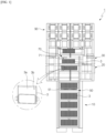
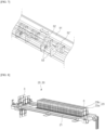
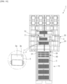
FIG. 1 is a plan view schematically illustrating a formation device of a pouch-type battery cell according to an exemplary embodiment of the present invention. -
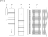
FIG. 2 is a schematic diagram ofFIG. 1 . -
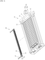
FIG. 3 is a perspective view schematically illustrating a charging part and a hole processing part of a formation device of a pouch-type battery cell according to an exemplary embodiment of the present invention. -
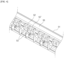
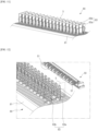
FIG. 4 is a perspective view schematically illustrating a hole processing part according to an exemplary embodiment of the present invention. -
FIG. 5 is a perspective view schematically illustrating a hole processing unit of a hole processing part according to an exemplary embodiment of the present invention. -
FIG. 6 is a diagram schematically illustrating the operation process of the hole processing part according to an exemplary embodiment of the present invention. -
FIG. 7 is a perspective view schematically illustrating one variant of a hole processing part according to an exemplary embodiment of the present invention. -
FIG. 8 is a perspective view schematically illustrating a loading buffer part/unloading buffer part according to an exemplary embodiment of the present invention. -
FIG. 9 is a perspective view schematically illustrating a sealing part according to an exemplary embodiment of the present invention. -
FIG. 10 is a plan view schematically illustrating a formation device of a pouch-type battery cell according to another exemplary embodiment of the present invention. -
FIG. 11 is a perspective view schematically illustrating a hole processing buffer part of a formation device of a pouch-type battery cell according to another exemplary embodiment of the present invention. -
FIG. 12 is a perspective view schematically illustrating a hole processing buffer part and a hole processing part of a formation device of a pouch-type battery cell according to another exemplary embodiment of the present invention. - The following is a detailed description of the present invention. It should be noted that the terms or words used in this specification and the claims of the patent are not to be construed in their ordinary or dictionary sense, but rather in a sense and concept consistent with the technical idea of the invention, based on the principle that the inventor may properly define the concept of a term to best describe his invention.
- The terms "comprise," "include" and "have" are used herein to designate the presence of characteristics, numbers, steps, actions, components or members described in the specification or a combination thereof, and it should be understood that the possibility of the presence or addition of one or more other characteristics, numbers, steps, actions, components, members or a combination thereof is not excluded in advance.
- In addition, when a part of a layer, a film, a region or a plate is disposed "on" another part, this includes not only a case in which one part is disposed "directly on" another part, but a case in which a third part is interposed there between. In contrast, when a part of a layer, a film, a region or a plate is disposed "under" another part, this includes not only a case in which one part is disposed "directly under" another part, but a case in which a third part is interposed there between. In addition, in this application, "on" may include not only a case of disposed on an upper part but also a case of disposed on a lower part.
- In addition, when a part of a layer, a film, a region or a plate is disposed "on" another part, this includes not only a case in which one part is disposed "directly on" another part, but a case in which a third part is interposed there between. In contrast, when a part of a layer, a film, a region or a plate is disposed "under" another part, this includes not only a case in which one part is disposed "directly under" another part, but a case in which a third part is interposed there between. In addition, in this application, "on" may include not only a case of disposed on an upper part but also a case of disposed on a lower part.
-
- *
FIG. 1 is a plan view schematically illustrating a formation device of a pouch-type battery cell according to an exemplary embodiment of the present invention.FIG. 2 is a schematic diagram ofFIG. 1 .FIG. 3 is a perspective view schematically illustrating a charging part and a hole processing part of a formation device of a pouch-type battery cell according to an exemplary embodiment of the present invention.FIG. 4 is a perspective view schematically illustrating a hole processing part according to an exemplary embodiment of the present invention.FIG. 5 is a perspective view schematically illustrating a hole processing unit of a hole processing part according to an exemplary embodiment of the present invention.FIG. 6 is a diagram schematically illustrating the operation process of the hole processing part according to an exemplary embodiment of the present invention.FIG. 7 is a perspective view schematically illustrating one variant of a hole processing part according to an exemplary embodiment of the present invention.FIG. 8 is a perspective view schematically illustrating a loading buffer part/unloading buffer part according to an exemplary embodiment of the present invention.FIG. 9 is a perspective view schematically illustrating a sealing part according to an exemplary embodiment of the present invention. - As shown in the drawings, a
formation device 1 of a pouch-type battery cells according to an exemplary embodiment of the present invention is configured by including a chargingpart 10 for charging abattery cell 3, aloading buffer part 20 where abattery cell 3 waits prior to being loaded into the chargingpart 10, an unloadingbuffer part 30 where abattery cell 3 waits that has been charged and taken out from the chargingpart 10, and ahole processing part 50 for forming adischarge hole 3b in agas pocket part 3a of thebattery cell 3, and a sealingpart 70 for sealing thedischarge hole 3b of thebattery cell 3. - The charging
part 10 is for activating thebattery cell 3 by charging and discharging thebattery cell 3 to a set charge and discharge condition, and includes aframe 12 for accommodating thebattery cell 3, a charging part (not shown) for charging and discharging thebattery cell 3, and apressure jig 11 for pressing thebattery cell 3. - The
pressure jig 11 may include ajig frame 13, a plurality ofpressure plates 15 disposed inside thejig frame 13, and a driving part 16 that drives the plurality ofpressure plates 15. - Between each of the
pressure plates 15, abattery cell 3 for performing the formation process may be disposed. - Here, the driving part 16 includes a
drive motor 16a and adrive shaft 16b, and when thedrive shaft 16b is rotated by the rotation of thedrive motor 16a, the plurality ofpressure plates 15 engaged therewith move unidirectionally, thereby enabling pressurization of both sides of thebattery cell 3. - The
loading buffer part 20 is a space provided for thebattery cells 3 to wait before being loaded into the chargingpart 10, and thebattery cells 3 are reloaded into theloading buffer part 20 by a loader/unloader 90. - Here, the
loading buffer part 20 includes atransfer part 21 for transferring thebattery cells 3, and a plurality ofalignment guide members 23 installed at certain distance apart along the transfer direction of thebattery cells 3 so that a plurality ofbattery cells 3 are arranged in an upright state. - In this case, the upright state of the
battery cell 3 means that thegas pocket part 3a is positioned in the upper side and the electrode assembly storing part (not shown) is positioned in the lower side. - The
loading buffer part 20 is a structure in which thebattery cell 3 is inserted into a gap space between onealignment guide member 23 among the plurality ofalignment guide members 23 and anotheralignment guide member 23 adjacent thereto. - To this end, the
alignment guide member 23 may include a pair ofguide bars guide bar 23a may support the right side of thebattery cell 3 and theother guide bar 23b may support the left side of thebattery cell 3. - At this time, the guide bars 23a, 23b may have a predetermined width and may extend in the height direction of the
battery cell 3. Furthermore, the height of the guide bars 23a, 23b may be slightly higher or lower than the height of thebattery cell 3, and is preferably located in an area where thehole processing unit 51 of thehole processing part 50 described later can approach thegas pocket part 3a of thebattery cell 3 and avoid interference with thehole processing unit 51 during formation of thedischarge hole 3b. - The unloading
buffer part 30 is a space provided for thebattery cells 3 that have been unloaded from the chargingpart 10 to wait after the formation process is completed, so that the sealing process can proceed through the sealingpart 70 described below, and they may be unloaded from theformation device 1 by the loader/unloader 90 upon completion of the sealing process. - Here, since the unloading
buffer part 30 is identical to the configuration of theloading buffer part 20, the detailed description of the unloadingbuffer part 30 will be replaced by the description of theloading buffer part 20, and the detailed description will be omitted hereinafter. - The
hole processing part 50 is for forming adischarge hole 3b in thegas pocket part 3a of thebattery cell 3 to discharge the internal gas of thebattery cell 3.
Here, thehole processing part 50 is provided on one side of the chargingpart 10 to form adischarge hole 3b in thegas pocket part 3a of thebattery cell 3 accommodated in the chargingpart 10. - Specifically, the
hole processing part 50 includes a plurality ofhole processing units 51 formed correspondingly to thebattery cells 3 arranged in the chargingpart 10 to form adischarge hole 3b in thegas pocket part 3a of eachbattery cell 3, a hole processingunit moving member 57 coupled to each of thehole processing units 51 to move thehole processing units 51 forward and backward in the direction of thebattery cells 3, and a driving part (not shown) to drive the hole processingunit moving member 57. - In this case, the
hole processing units 51 are formed in a plurality corresponding to thebattery cells 3 arranged in the chargingpart 10, so that the plurality ofhole processing units 51 can simultaneously form the discharge holes 3b in thegas pocket parts 3a of thebattery cells 3. - Here, the hole processing
unit moving member 57 is configured to move forward in the direction of thebattery cell 3 to perform a hole processing process on thebattery cell 3 with thehole processing unit 51, or to move backward to its original position after completion of the hole processing process, and to this end, the hole processingunit moving member 57 may be made of a sliding structure or a cylinder structure capable of moving forward and backward in the direction of thebattery cell 3. Since the above structure is a general configuration, a detailed description will be omitted hereinafter. - Meanwhile, the
hole processing unit 51 includes a pair of gaspocket pressing members 52, 52' for pressing thegas pocket part 3a of thebattery cell 3, and ahole processing member 53 installed on the inner side of the gaspocket pressing members 52, 52', respectively, so that when thegas pocket part 3a is pressed with the gaspocket pressing members 52, 52', a portion of the press surface is penetrated to form adischarge hole 3b, and a holeprocessing unit body 55 in which the pair of gaspocket pressing members 52, 52' is movably installed facing thegas pocket part 3a, wherein the holeprocessing unit body 55 is connected to a hole processingunit moving member 57 to be moved forward and backward in the direction of thebattery cell 3. - Here, the gas
pocket pressing member 52, 52' is for pressing and fixing thegas pocket part 3a of thebattery cell 3, and thehole processing member 53 presses thebattery cell 3 so that thebattery cell 3 remains fixed when thedischarge hole 3b is formed on thegas pocket part 3a. - And, the hole
processing unit body 55 has a side coupled with the gaspocket pressing members 52, 52' connected in a sliding structure to slidingly move the pair of gaspocket pressing members 52, 52' in a direction of moving closer to each other or in a direction of moving further away from each other. - As a result, the gas
pocket pressing members 52, 52' slide in the direction of moving closer to each other when pressing thegas pocket part 3a, and slide in the direction of moving away from each other to release the pressing state when the hole processing process is completed. - Here, the pair of gas
pocket pressing members 52, 52' can be sealed with thegas pocket part 3a interposed therebetween, and in this case, when slidingly moving to press thebattery cell 3, the sliding movement can be stopped at a point where the gap between them becomes the thickness length of thegas pocket part 3a. - Meanwhile, the gas
pocket pressing member 52, 52' is provided with a press surface on the inner side facing thebattery cell 3 for pressing by contacting both sides in the thickness direction of thegas pocket part 3a, and ahole processing member 53 is installed in a portion of the press surface. - Here, the
hole processing member 53 is preferably made of a shape or material capable of forming adischarge hole 3b in thegas pocket part 3a, but more preferably, thehole processing member 53 may comprise a horn-shapedmember 53a having a pointed end and a horn-shapedmember groove 53b forming a recess that is recessed inwardly by at least as much as the pointed part of the horn-shapedmember 53a. - Furthermore, the
hole processing member 53 may be a punching mold, and various other modifications can be made. - Meanwhile, the gas
pocket pressing members 52, 52' may be coupled with apressure pad 52a having an elasticity at an extending part on one side thereof to prevent damage to thebattery cell 3 when pressing thebattery cell 3. Here, the extending part on one side refers to a portion of the one side extending from the gaspocket pressing member 52, 52' toward thebattery cell 3. - In accordance with the structure as described above, the gas
pocket pressing members 52, 52' are moved forward and backward toward thebattery cell 3 by the movement of the hole processingunit moving member 57, and the pair of gaspocket pressing members 52, 52' moved forward toward thebattery cell 3 are moved toward thegas pocket part 3a of thebattery cell 3 in a direction that brings them closer to each other, and then adischarge hole 3b can be formed in thegas pocket part 3a with thehole processing member 53 while pressing thegas pocket part 3a, and through the plurality of gaspocket pressing members 52, 52' and respectivehole processing members 53 formed thereon, it is possible to simultaneously form adischarge hole 3b in thegas pocket part 3a of a plurality ofbattery cells 3 arranged in the chargingpart 10. - In an exemplary embodiment of the present invention, a
hole processing unit 51 of thehole processing part 50 is formed in plurality to simultaneously form agas pocket part 3a for a plurality ofbattery cells 3 arranged in the chargingpart 10, but as shown inFIG. 7 , ahole processing unit 51 of thehole processing part 50 is provided as one, but it is also possible that the holeprocessing unit body 55, which is coupled to a pair of gaspocket pressing members 52, 52' of thehole processing unit 51, is slidably movably coupled to the longitudinal direction of the hole processingunit moving member 57 to move the gaspocket pressing members 52, 52' toward or away from each other, so that thehole processing unit 51 sequentially forms adischarge hole 3b in thegas pocket part 3a of eachbattery cell 3. - In this case, the gas
pocket pressing member 52, 52' is moved forwardly toward thebattery cell 3 via the hole processingunit moving member 57 to form adischarge hole 3b in thegas pocket part 3a of one of thebattery cells 3, and after forming thedischarge hole 3b, it is moved backwardly to return to its original position, and the holeprocessing unit body 55 is moved on the hole processingunit moving member 57, and it moves in the thickness direction of thebattery cell 3 and then moves forwardly toward thebattery cell 3 via the hole processingunit moving member 57, such as forming thedischarge hole 3b in thegas pocket part 3a of theother battery cell 3, and the holeprocessing unit body 55 moves forwardly/backwardly toward thebattery cell 3 via the hole processingunit moving member 57, and the holeprocessing unit body 55 slidingly moves on the hole processingunit moving member 57 to form adischarge hole 3b in thegas pocket part 3a of thebattery cell 3, so that thedischarge hole 3b can be formed sequentially in thebattery cell 3. - The sealing
part 70 is for sealing thedischarge hole 3b formed in thegas pocket part 3a of thebattery cell 3. In the present invention, the meaning of sealing thedischarge hole 3b includes sealing thedischarge hole 3b by sealing thedischarge hole 3b or sealing the periphery of thedischarge hole 3b. - Specifically, the sealing
part 70 includes a sealingunit 71 for sealing thedischarge hole 3b while pressing both sides of thegas pocket part 3a, a sealingunit moving member 77 coupled to one side of the sealingunit 71 for moving the sealingunit 71 forwardly or backwardly in the direction of thebattery cell 3, and a driving part (not shown) for driving the sealingunit moving member 77. - Here, the sealing
unit 71 is installed on each inner side of the pair of dischargehole press members 72, 72' which presses thedischarge hole 3b and its periphery, and the pair of dischargehole press members 72, 72', and when the dischargehole press member 72, 72' is used to press thedischarge hole 3b and its periphery, a pair of sealingmembers 73 for sealing thedischarge hole 3b or a periphery thereof, and the pair of dischargehole press members 72, 72' include asealing unit body 75 movably installed toward thedischarge hole 3b, wherein thesealing unit body 75 is connected to a sealingunit moving member 77 to move forwardly and backwardly in the direction of thebattery cell 3. - Here, the discharge
hole press members 72, 72' are for pressing and fixing thedischarge hole 3b of thegas pocket part 3a, and they press thebattery cell 3 so that thebattery cell 3 remains fixed when thedischarge hole 3b is sealed with the sealingmember 73. - And, the sealing
unit body 75 connected in a sliding structure on the side that is coupled to the dischargehole press members 72, 72' to slidingly move the pair of dischargehole press members 72, 72' in the direction of moving closer to each other or further away from each other. - As a result, the discharge
hole press members 72, 72' slide in a direction toward each other when pressing thedischarge hole 3b or its surroundings, and slide in a direction away from each other to release the pressed state when the sealing process is completed. - According to the structure as described above, the
battery cell 3 can be pressed with the dischargehole pressing member 72, 72' to keep thebattery cell 3 in a fixed state, and then the dischargehole pressing member 72, 72' can press and seal thedischarge hole 3b of thebattery cell 3 and its surroundings. - Here, the sealing
part 70 is preferably provided on one side of the unloadingbuffer part 30 and is configured to seal thedischarge hole 3b formed in thegas pocket part 3a of the chargedbattery cell 3, but is not limited thereto. - It is also possible, but not limited to, that the sealing
unit 71 of the sealingpart 70 is formed in plurality to seal the discharge holes 3b of a plurality ofbattery cells 3 arranged in the unloadingbuffer part 30. - Meanwhile, the pair of sealing
members 73 comprises a pair of sealing tools (not shown) for sealing the periphery of thedischarge hole 3b, so as to heat-seal the pouch by heat-pressing the periphery of thedischarge hole 3b.
The sealing tool may be, but is not limited to, a hard metal material having good thermal conductivity. - Here, the shape of the sealing tool may be varied, and the sealing tool may be "U" shaped, "-" shaped, "L" shaped, " ⊏ " shaped, etc. so that sealing in and around the
discharge hole 3b is advantageous, and various methods disclosed at the time of filing of the present invention may be employed, without being limited to these embodiments. - Meanwhile, the sealing
member 73 may comprise a tape that seals the area including thedischarge hole 3b, and may be configured to bond thedischarge hole 3b. - In this case, the discharge
hole pressing members 72, 72' may be coupled with apressure pad 72a having an elasticity at one extending part thereof to prevent damage to the pouch during pressing. - Here, since the operation process of the sealing
part 70 approaching thebattery cell 3 is the same as the operation process of thehole processing part 50 approaching thebattery cell 3, the description of operation process of the sealingpart 70 will be replaced, and the following detailed description will be omitted. - Meanwhile, in order to discharge the internal gas generated in the
battery cell 3 to the outside during the formation process of the pouch-type battery cell through the formation device according to the present invention, the upper part of the formation device may include an air supply part (not shown) and a gas exhaust part (not shown). - The air supply part is arranged to introduce and supply air from the outside into the formation device, and the gas exhaust part is configured to discharge gas generated during the formation process to the outside.
- Hereinafter, the operation process of the formation device of a pouch-type battery cell according to an exemplary embodiment of the present invention will be described schematically with reference to the drawings.
- First, the manufactured pouch-
type battery cell 3 is supplied to theloading buffer part 20, and thebattery cell 3 supplied to theloading buffer part 20 is supplied to the chargingpart 10 to perform charging and discharging. - The
battery cell 3 supplied to the chargingpart 10 performs a predetermined charge and discharge using a charge and discharge device to activate the battery. - Specifically, the
battery cell 3 supplied to the chargingpart 10 performs a partial charging to partially expand thegas pocket part 3a. - In this case, the partial charging may be performed at 50% or less of the total charging capacity of the
battery cell 3. - In this way, the
gas pocket part 3a of thebattery cell 3 is partially expanded to a predetermined size through the chargingpart 10, and adischarge hole 3b is formed in thegas pocket part 3a through thehole processing part 50 provided on one side of the chargingpart 10. - At this time, when the
hole processing units 51 of thehole processing part 50 are formed in a plurality corresponding to thebattery cells 3 arranged in the chargingpart 10, all thehole processing units 51 can simultaneously form thedischarge hole 3b for all thebattery cells 3 arranged in the chargingpart 10 while moving forward and backward toward thebattery cells 3. - In this way, the
hole processing part 50 provided on one side of the chargingpart 10 can move forward toward thebattery cells 3 accommodated in the chargingpart 10 and form adischarge hole 3b in thegas pocket part 3a of all thebattery cells 3 arranged in the chargingpart 10, and after forming thedischarge hole 3b in thegas pocket part 3a, it can move backward to return to its original position. - Meanwhile, when the
hole processing unit 51 of thehole processing part 50 is provided as one, thehole processing unit 51 moves by sliding forward and backward toward thebattery cell 3 corresponding to the movement direction of thebattery cell 3 on the hole processingunit moving member 57 to form thedischarge hole 3b sequentially in thebattery cell 3 arranged in the chargingpart 10. - As described above, the
gas pocket part 3a is arranged in the chargingpart 10 through thehole processing part 50, but by performing partial charging to form thedischarge hole 3b in the partially chargedbattery cell 3, it is possible to prevent the gas and electrolyte inside thebattery cell 3 from being discharged together at the time of forming thedischarge hole 3b in thebattery cell 3 due to overexpansion of thegas pocket part 3a during charging of theconventional battery cell 3, and to prevent contamination of the formation device by the electrolyte. - In other words, conventionally, when electrolyte is injected into the pouch-
type battery cell 3 in the assembly stage, the electrolyte is discharged together with the internal gas of the pouch-type battery cell 3 at the time of discharge due to the vacuum-tight part of thegas pocket part 3a and the internal pressure when thedischarge hole 3b is formed, but by partially charging thebattery cell 3 through the formation device according to the present invention, the vacuum-tight part of thegas pocket part 3a is expanded to a predetermined size, and the internal pressure of thebattery cell 3 is formed to a certain size, and the vacuum-tight part of thegas pocket part 3a is spaced apart so that only the gas excluding the electrolyte can be stably discharged. - And, the charging
part 10 performs residual charging after discharging the gas through thedischarge hole 3b of thegas pocket part 3a. - That is, through the
hole processing part 50 provided on one side of the chargingpart 10, adischarge hole 3b is formed in thegas pocket part 3a of the partially chargedbattery cell 3 to discharge only the gas inside thebattery cell 3 to the outside, and then a residual charging is performed on thebattery cell 3 through the chargingpart 10. - Here, the gas generated during the residual charging of the
battery cell 3 can be stably discharged through thedischarge hole 3b of thegas pocket part 3a. - In this case, the residual charging may be up to 70% of the total charge capacity of the
battery cell 3. - In this way, after partially charging the
battery cell 3, a discharge hole is formed in the partially chargedbattery cell 3 to discharge only the gas inside thebattery cell 3 to the outside, and then, while performing the residual charging, thebattery cell 3 can be charged while stably discharging only the gas without discharging the electrolyte by discharging the gas inside thebattery cell 3 to the outside again. - As described above, the
battery cells 3 having completed the residual charging are transferred from the chargingpart 10 to the unloadingbuffer part 30, and thebattery cells 3 transferred to the unloadingbuffer part 30 are configured to seal thedischarge hole 3b of eachbattery cell 3 through the sealingpart 70 provided on one side of the unloadingbuffer part 30. - Then, the
battery cell 3 in which the sealing of thedischarge hole 3b formed in thegas pocket 3a is completed is transferred to the post-process to be productized. -
FIG. 10 is a plan view schematically illustrating a formation device of a pouch-type battery cell according to another exemplary embodiment of the present invention.FIG. 11 is a perspective view schematically illustrating a hole processing buffer part of a formation device of a pouch-type battery cell according to another exemplary embodiment of the present invention.FIG. 12 is a perspective view schematically illustrating a hole processing buffer part and a hole processing part of a formation device of a pouch-type battery cell according to another exemplary embodiment of the present invention. - As shown in the drawings, the formation device 1' according to another exemplary embodiment of the present invention may further include a hole
processing buffer part 80 in which the chargedbattery cells 3 wait to form adischarge hole 3b on the chargingpart 10. - Here, the hole
processing buffer part 80 may include aprocessing plate 81, and a plurality of hole processingalignment guide members 83 installed by being spaced apart at certain distance in the longitudinal direction of theprocessing plate 81 so that thebattery cell 3 is arranged on the upper part of theprocessing plate 81. - That is, the hole
processing buffer part 80 includes aprocessing plate 81 on which a plurality ofbattery cells 3 are arranged, and a plurality of hole processingalignment guide members 83 installed at certain distance along the thickness direction of thebattery cells 3 so that thebattery cells 3 are arranged in an upright state on the processing plate. - Here, the
battery cell 3 is inserted and installed in the gap space between one of the hole processingalignment guide members 83 of the plurality of holeprocessing buffer parts 80 and the other hole processingalignment guide member 83 adjacent thereto. - To this end, the hole processing
alignment guide member 83 may include a pair of holeprocessing guide bars processing guide bar 83a supports the right side of thebattery cell 3 and the other holeprocessing guide bar 83b supports the left side of thebattery cell 3. - Meanwhile, as in the present embodiment, when a hole
processing buffer part 80 is provided on the chargingpart 10, as in the present embodiment, ahole processing part 50 is provided on one side of the holeprocessing buffer part 80 to form adischarge hole 3b in thegas pocket part 3a of thebattery cell 3 accommodated in the holeprocessing buffer part 80. - According to the structure as described above, after being transferred from the
loading buffer part 20 to the chargingpart 10, a partial charging is performed on the chargingpart 10 to partially expand thegas pocket part 3a of thebattery cell 3, and after transferring the partially expandedbattery cell 3 to the holeprocessing buffer part 80, adischarge hole 3b is formed in thegas pocket part 3a of thebattery cell 3 accommodated in the holeprocessing buffer part 80 through thehole processing part 50 provided on one side of the holeprocessing buffer part 80. Thebattery cell 3 in which thedischarge hole 3b is formed through the holeprocessing buffer part 80 is transferred to the chargingpart 10, and then residual charging can be performed on thebattery cell 3 through the chargingpart 10. - Again, when the
hole processing units 51 of thehole processing part 50 are formed in a plurality corresponding to thebattery cells 3 arranged in the holeprocessing buffer part 80, all thehole processing units 51 of thehole processing part 50 move forward toward thebattery cells 3 and then form thedischarge hole 3b while pressing all thebattery cells 3 accommodated in the holeprocessing buffer part 80. After forming thedischarge hole 3b in thegas pocket part 3a of all thebattery cells 3, all thehole processing units 51 of thehole processing part 50 may again be configured to move backward. - Furthermore, when the
hole processing unit 51 of thehole processing part 50 is formed as one, thehole processing unit 51 moves forward toward thebattery cell 3 and then moves toward one of thebattery cells 3 accommodated in the holeprocessing buffer part 80, and then thehole processing unit 51 of thehole processing part 50 forms thedischarge hole 3b while pressing thebattery cell 3. After forming thedischarge hole 3b, it moves backward, then moves toward thebattery cell 3 in the thickness direction of thebattery cell 3, then moves forward again to form thedischarge hole 3b in the correspondingbattery cell 3, and so on, and the above process may be repeatedly performed to form thedischarge hole 3b sequentially in all thebattery cells 3 arranged in the holeprocessing buffer part 80. - While the present invention has been shown and described with reference to certain embodiments, it will be readily apparent to one of ordinary skill in the art that various modifications and changes can be made without departing from the ideas and scope of the invention as set forth in the appended claims.
-
- 1, 1': FORMATION DEVICE FOR POUCH-TYPE BATTERY CELLS
- 3: BATTERY CELL
- 3a: GAS POCKET PART
- 3b: DISCHARGE HOLE
- 10: CHARGING PART
- 11: PRESSURE JIG
- 12: FRAME
- 13: JIG FRAME
- 15: PRESSURE PLATE
- 16: DRIVING PART
- 16a: DRIVE MOTOR
- 16b: DRIVE SHAFT
- 20: LOADING BUFFER PART
- 21: TRANSFER PART
- 23: ALIGNMENT GUIDE MEMBER
- 23a, 23b: GUIDE BAR
- 30: UNLOADING BUFFER PART
- 50: HOLE PROCESSING PART
- 51: HOLE PROCESSING UNIT
- 52, 52': GAS POCKET PRESSING MEMBER
- 52a: PRESSURE PAD
- 53: HOLE PROCESSING MEMBER
- 53a: HORN-SHAPED MEMBER
- 53b: HORN-SHAPED MEMBER GROOVE
- 55: HOLE PROCESSING UNIT BODY
- 57: HOLE PROCESSING UNIT MOVING MEMBER
- 70: SEALING PART
- 71: SEALING UNIT
- 72, 72': DISCHARGE HOLE PRESS MEMBER
- 72a: PRESSURE PAD
- 73: SEALING MEMBER
- 75: SEALING UNIT BODY
- 77: SEALING UNIT MOVING MEMBER
- 80: HOLE PROCESSING BUFFER PART
- 81: PROCESSING PLATE
- 83: HOLE PROCESSING ALIGNMENT GUIDE MEMBER
- 83a, 83b: HOLE PROCESSING GUIDE BAR
- 90: LOADER/UNLOADER
Claims (12)
- A formation device of a pouch-type battery cell comprising:a charging part that charges a battery cell;a loading buffer part where a battery cell waits before being placed in the charging part;an unloading buffer part in which a battery cell that has been charged and removed from the charging part waits;a hole processing part forming a discharge hole in a gas pocket part of the battery cell; anda sealing part that seals the discharge hole of the battery cell.
- The formation device of a pouch-type battery cell of claim 1, wherein
the charging part performs a partial charging on the battery cell to partially expand the gas pocket part. - The formation device of a pouch-type battery cell of claim 2, wherein
a partial charging is performed on the battery cell to partially expand the gas pocket part, and then a discharge hole is formed in the gas pocket part of the battery cell through the hole processing part. - The formation device of a pouch-type battery cell of claim 3, wherein
the charging part performs residual charging after discharging gas through a discharge hole of the gas pocket part. - The formation device of a pouch-type battery cell of claim 1, wherein
the hole processing part is provided on one side of a charging part and forms a discharge hole in a gas pocket part of a battery cell accommodated in a charging part. - The formation device of a pouch-type battery cell of claim 5, wherein
the hole processing part comprises:a plurality of hole processing units formed correspondingly to the battery cells arranged in the charging part to form a discharge hole in a gas pocket part of each battery cell, a hole processing unit moving member coupled to each of the hole processing units to move the hole processing unit forwardly and backwardly in the direction of the battery cell, and a driving part to drive the hole processing unit moving member, whereinthe plurality of hole processing units simultaneously forms discharge holes in the gas pocket parts of the battery cells. - The formation device of a pouch-type battery cell of claim 6, wherein
the hole processing unit comprises:
a pair of gas pocket pressing members for pressing a gas pocket part of the battery cell, a hole processing member installed respectively on an inner side of the gas pocket pressing member to form a discharge hole on a press surface of the gas pocket part when pressing the gas pocket part, and a hole processing unit body coupled to one side of the gas pocket pressing member to move the gas pocket pressing member in a direction toward or away from each other. - The formation device of a pouch-type battery cell of claim 5, wherein
the hole processing part comprises:a single hole processing unit forming a discharge hole in a gas pocket part of a battery cell arranged in the charging part, a hole processing unit moving member coupled to the hole processing unit to move the hole processing unit forwardly and backwardly in the direction of the battery cell, and a driving part to drive the hole processing unit moving member, whereinthe hole processing unit sequentially forms a discharge hole in a gas pocket part of each battery cell. - The formation device of a pouch-type battery cell of claim 8, wherein
the hole processing unit comprises:
a pair of gas pocket pressing members for pressing a gas pocket part of a battery cell, a hole processing member installed on an inner side of each of the gas pocket pressing members to form a discharge hole on a press surface of the gas pocket part when pressing the gas pocket part, and a hole processing unit body coupled to one side of the gas pocket pressing members to move the gas pocket pressing members toward or away from each other, and slidably movably coupled to the hole processing unit moving member. - The formation device of a pouch-type battery cell of claim 1, further comprising:
a hole processing buffer part where a charged battery cell waits to form a discharge hole on the charging part. - The formation device of a pouch-type battery cell of claim 10, wherein
the hole processing buffer part comprises:
a processing plate, and a plurality of alignment guide members installed by being spaced apart from the processing plate at a certain distance such that the battery cell is arranged on an upper part of the processing plate. - The formation device of a pouch-type battery cell of claim 10, wherein
the hole processing part is provided on one side of the hole processing buffer part to form a discharge hole in a gas pocket part of a battery cell accommodated in the hole processing buffer part.
Applications Claiming Priority (2)
| Application Number | Priority Date | Filing Date | Title |
|---|---|---|---|
| KR1020220113045A KR20240034020A (en) | 2022-09-06 | 2022-09-06 | Formation apparatus of pouch type battery cell |
| PCT/KR2023/013281 WO2024054013A1 (en) | 2022-09-06 | 2023-09-05 | Formation device of pouch-type battery cell |
Publications (3)
| Publication Number | Publication Date |
|---|---|
| EP4496051A1 true EP4496051A1 (en) | 2025-01-22 |
| EP4496051A4 EP4496051A4 (en) | 2025-09-17 |
| EP4496051B1 EP4496051B1 (en) | 2026-04-29 |
Family
ID=90191548
Family Applications (1)
| Application Number | Title | Priority Date | Filing Date |
|---|---|---|---|
| EP23863480.2A Active EP4496051B1 (en) | 2022-09-06 | 2023-09-05 | Formation device of pouch-type battery cell |
Country Status (6)
| Country | Link |
|---|---|
| US (1) | US12463234B2 (en) |
| EP (1) | EP4496051B1 (en) |
| JP (1) | JP7838854B2 (en) |
| KR (1) | KR20240034020A (en) |
| CN (1) | CN119032445A (en) |
| WO (1) | WO2024054013A1 (en) |
Family Cites Families (24)
| Publication number | Priority date | Publication date | Assignee | Title |
|---|---|---|---|---|
| KR100709881B1 (en) * | 2005-09-28 | 2007-04-20 | 삼성에스디아이 주식회사 | Pouch-type lithium secondary battery and method for manufacturing same |
| KR101159099B1 (en) * | 2009-12-01 | 2012-06-22 | 주식회사 엘지화학 | Pouch-Type Battery Case Having Gas-Gathering Residue Portion |
| CN103069620A (en) | 2010-10-01 | 2013-04-24 | 株式会社东芝 | Nonaqueous electrolyte secondary battery and method for manufacturing same |
| KR20130024807A (en) | 2011-08-29 | 2013-03-08 | 정윤이 | Cell formation module, apparatus and method for processing cell formation with the cell formation modules |
| JP2013143309A (en) | 2012-01-12 | 2013-07-22 | Hitachi Maxell Ltd | Tray, main tray, and tray set |
| EP2860809B1 (en) | 2012-06-11 | 2017-10-18 | Nissan Motor Co., Ltd | Manufacturing method and manufacturing device of secondary battery |
| KR101558049B1 (en) | 2013-09-30 | 2015-10-06 | 주식회사 엘지화학 | Method for manufacturing second battery |
| KR20150037007A (en) * | 2013-09-30 | 2015-04-08 | 서송교 | Photo-therapeutic hat using lighting sheet |
| JP6488969B2 (en) | 2015-09-30 | 2019-03-27 | 日産自動車株式会社 | Secondary battery manufacturing equipment |
| KR102119551B1 (en) * | 2016-04-01 | 2020-06-05 | 주식회사 엘지화학 | Rack-Typed Charging and Discharging Apparatus |
| KR102106111B1 (en) | 2016-12-20 | 2020-04-29 | 주식회사 엘지화학 | Method for injecting electrolyte of pouch type battery |
| KR102335202B1 (en) | 2017-02-20 | 2021-12-03 | 주식회사 엘지에너지솔루션 | Secondary Battery with improved Stability having Heat Expandable layer and Method thereof |
| KR102320016B1 (en) * | 2017-12-15 | 2021-11-02 | 주식회사 엘지에너지솔루션 | Manufacturin method of rechargeable battery |
| KR20190074591A (en) | 2017-12-20 | 2019-06-28 | 주식회사 엘지화학 | Manufacturin method and manufacturin device of rechargeable battery |
| KR102772424B1 (en) * | 2019-08-05 | 2025-02-25 | 주식회사 엘지에너지솔루션 | Degassing apparatus for secondary battery and degassing method for secondary battery using the same |
| KR102689325B1 (en) | 2020-01-07 | 2024-07-30 | 주식회사 엘지에너지솔루션 | Rechargeable battery manufacturing device and rechargeable battery manufacturing method |
| KR102798481B1 (en) | 2020-01-10 | 2025-04-22 | 주식회사 엘지에너지솔루션 | Pressurized jig for removing gas traps and a method of manufacturing a secondary battery using the same |
| KR102858137B1 (en) | 2020-02-28 | 2025-09-11 | 주식회사 엘지에너지솔루션 | Method for manufacturing secondary battery |
| KR102807656B1 (en) | 2020-05-13 | 2025-05-14 | 주식회사 엘지에너지솔루션 | Rechargeable battery |
| CN114902481B (en) | 2020-09-25 | 2024-02-09 | 株式会社Lg新能源 | Degassing device and degassing method for secondary battery |
| KR102556804B1 (en) | 2021-02-01 | 2023-07-18 | (주) 에이프로 | Pressure activation apparatus with transfer unit |
| KR20220113045A (en) | 2021-02-05 | 2022-08-12 | 엘지전자 주식회사 | Electric heater |
| JP7108117B1 (en) | 2021-09-30 | 2022-07-27 | 積水化学工業株式会社 | Solid polymer electrolyte, lithium ion secondary battery, method for producing lithium ion secondary battery |
| KR102416581B1 (en) | 2021-12-24 | 2022-07-05 | 주식회사 티엠프라자 | Battery cell apparatus for removing gas |
-
2022
- 2022-09-06 KR KR1020220113045A patent/KR20240034020A/en active Pending
-
2023
- 2023-09-05 CN CN202380036763.9A patent/CN119032445A/en active Pending
- 2023-09-05 JP JP2024560861A patent/JP7838854B2/en active Active
- 2023-09-05 EP EP23863480.2A patent/EP4496051B1/en active Active
- 2023-09-05 US US18/861,046 patent/US12463234B2/en active Active
- 2023-09-05 WO PCT/KR2023/013281 patent/WO2024054013A1/en not_active Ceased
Also Published As
| Publication number | Publication date |
|---|---|
| US20250309319A1 (en) | 2025-10-02 |
| JP2025513905A (en) | 2025-04-30 |
| KR20240034020A (en) | 2024-03-13 |
| EP4496051B1 (en) | 2026-04-29 |
| JP7838854B2 (en) | 2026-04-01 |
| US12463234B2 (en) | 2025-11-04 |
| EP4496051A4 (en) | 2025-09-17 |
| WO2024054013A1 (en) | 2024-03-14 |
| CN119032445A (en) | 2024-11-26 |
Similar Documents
| Publication | Publication Date | Title |
|---|---|---|
| US20240313249A1 (en) | Formation Device for Battery Cell | |
| KR102763834B1 (en) | Apparatus for manufacturing pouch type secondary battery | |
| EP3419076A2 (en) | Pouch-type secondary battery and pouch film forming apparatus | |
| EP3886231B1 (en) | Sequential pressure formation jig and formation method using same | |
| KR102119551B1 (en) | Rack-Typed Charging and Discharging Apparatus | |
| EP4496051B1 (en) | Formation device of pouch-type battery cell | |
| KR20200084579A (en) | Battery pack and apparatus for assembling battery pack | |
| CN119343198A (en) | Welding method, welding device, welding equipment and battery cell | |
| JP3565539B2 (en) | Battery manufacturing equipment | |
| CN118336073B (en) | A battery grouping device, production line and battery grouping method | |
| KR102935546B1 (en) | Pressurization activation device in which the degassing process is carried out | |
| CN222359562U (en) | Battery clamping device, battery welding equipment and battery production system | |
| US20240154146A1 (en) | Apparatus and method for assembling cell block of battery | |
| KR102614097B1 (en) | stage module for manufacturing electrode assembly and carrier for transporting electrode assembly and electrode assembly manufacturing method | |
| KR102766981B1 (en) | Apparatus for manufacturing secondary battery and method for manufacturing secondary battery using the same | |
| EP4496052A1 (en) | Formation method for pouch-type battery cells | |
| KR20220126634A (en) | Battery cell manufacturing method and device | |
| CN222859899U (en) | Rubberizing equipment and battery production line | |
| KR102728378B1 (en) | Equipment for manufacturing cell stacks for secondary batteries that includes a separator grip device that can prevent damage to the battery separator | |
| EP4489155A1 (en) | Electrode assembly sealing device and sealing method | |
| EP4235888B1 (en) | Manufacturing device for electrode assembly and method using the same | |
| JP2026509950A (en) | Battery Activation Device | |
| KR20260068448A (en) | Manufacturing apparatus and manufacturing method for battery cell | |
| KR20260042894A (en) | Folding apparatus and battery cell manufactured by the same | |
| CN118805280A (en) | Apparatus and method for sealing an electrode assembly |
Legal Events
| Date | Code | Title | Description |
|---|---|---|---|
| STAA | Information on the status of an ep patent application or granted ep patent |
Free format text: STATUS: THE INTERNATIONAL PUBLICATION HAS BEEN MADE |
|
| PUAI | Public reference made under article 153(3) epc to a published international application that has entered the european phase |
Free format text: ORIGINAL CODE: 0009012 |
|
| STAA | Information on the status of an ep patent application or granted ep patent |
Free format text: STATUS: REQUEST FOR EXAMINATION WAS MADE |
|
| 17P | Request for examination filed |
Effective date: 20241015 |
|
| AK | Designated contracting states |
Kind code of ref document: A1 Designated state(s): AL AT BE BG CH CY CZ DE DK EE ES FI FR GB GR HR HU IE IS IT LI LT LU LV MC ME MK MT NL NO PL PT RO RS SE SI SK SM TR |
|
| A4 | Supplementary search report drawn up and despatched |
Effective date: 20250821 |
|
| RIC1 | Information provided on ipc code assigned before grant |
Ipc: H01M 10/04 20060101AFI20250814BHEP Ipc: H01M 10/44 20060101ALI20250814BHEP Ipc: H01M 4/04 20060101ALI20250814BHEP Ipc: H01M 50/342 20210101ALI20250814BHEP Ipc: H01M 50/30 20210101ALI20250814BHEP Ipc: H01M 50/105 20210101ALI20250814BHEP |
|
| DAV | Request for validation of the european patent (deleted) | ||
| DAX | Request for extension of the european patent (deleted) | ||
| GRAP | Despatch of communication of intention to grant a patent |
Free format text: ORIGINAL CODE: EPIDOSNIGR1 |
|
| STAA | Information on the status of an ep patent application or granted ep patent |
Free format text: STATUS: GRANT OF PATENT IS INTENDED |
|
| RIC1 | Information provided on ipc code assigned before grant |
Ipc: H01M 10/04 20060101AFI20251219BHEP Ipc: H01M 10/44 20060101ALI20251219BHEP Ipc: H01M 4/04 20060101ALI20251219BHEP Ipc: H01M 10/52 20060101ALI20251219BHEP Ipc: H01M 50/655 20210101ALI20251219BHEP |
|
| INTG | Intention to grant announced |
Effective date: 20260112 |
|
| GRAS | Grant fee paid |
Free format text: ORIGINAL CODE: EPIDOSNIGR3 |
|
| P01 | Opt-out of the competence of the unified patent court (upc) registered |
Free format text: CASE NUMBER: UPC_APP_0005795_4496051/2026 Effective date: 20260217 |
|
| GRAA | (expected) grant |
Free format text: ORIGINAL CODE: 0009210 |
|
| STAA | Information on the status of an ep patent application or granted ep patent |
Free format text: STATUS: THE PATENT HAS BEEN GRANTED |
|
| AK | Designated contracting states |
Kind code of ref document: B1 Designated state(s): AL AT BE BG CH CY CZ DE DK EE ES FI FR GB GR HR HU IE IS IT LI LT LU LV MC ME MK MT NL NO PL PT RO RS SE SI SK SM TR |
|
| REG | Reference to a national code |
Ref country code: CH Ref legal event code: F10 Free format text: ST27 STATUS EVENT CODE: U-0-0-F10-F00 (AS PROVIDED BY THE NATIONAL OFFICE) Effective date: 20260429 Ref country code: GB Ref legal event code: FG4D |