EP4496021A1 - Method of manufacturing dry-processed electrode and obtained dry-processed electrode - Google Patents
Method of manufacturing dry-processed electrode and obtained dry-processed electrode Download PDFInfo
- Publication number
- EP4496021A1 EP4496021A1 EP24189817.0A EP24189817A EP4496021A1 EP 4496021 A1 EP4496021 A1 EP 4496021A1 EP 24189817 A EP24189817 A EP 24189817A EP 4496021 A1 EP4496021 A1 EP 4496021A1
- Authority
- EP
- European Patent Office
- Prior art keywords
- dry
- binder
- mass
- mixing
- dispersion
- Prior art date
- Legal status (The legal status is an assumption and is not a legal conclusion. Google has not performed a legal analysis and makes no representation as to the accuracy of the status listed.)
- Granted
Links
Images

Classifications
-
- H—ELECTRICITY
- H01—ELECTRIC ELEMENTS
- H01M—PROCESSES OR MEANS, e.g. BATTERIES, FOR THE DIRECT CONVERSION OF CHEMICAL ENERGY INTO ELECTRICAL ENERGY
- H01M4/00—Electrodes
- H01M4/02—Electrodes composed of, or comprising, active material
- H01M4/04—Processes of manufacture in general
- H01M4/0402—Methods of deposition of the material
- H01M4/0404—Methods of deposition of the material by coating on electrode collectors
-
- C—CHEMISTRY; METALLURGY
- C09—DYES; PAINTS; POLISHES; NATURAL RESINS; ADHESIVES; COMPOSITIONS NOT OTHERWISE PROVIDED FOR; APPLICATIONS OF MATERIALS NOT OTHERWISE PROVIDED FOR
- C09J—ADHESIVES; NON-MECHANICAL ASPECTS OF ADHESIVE PROCESSES IN GENERAL; ADHESIVE PROCESSES NOT PROVIDED FOR ELSEWHERE; USE OF MATERIALS AS ADHESIVES
- C09J127/00—Adhesives based on homopolymers or copolymers of compounds having one or more unsaturated aliphatic radicals, each having only one carbon-to-carbon double bond, and at least one being terminated by a halogen; Adhesives based on derivatives of such polymers
- C09J127/02—Adhesives based on homopolymers or copolymers of compounds having one or more unsaturated aliphatic radicals, each having only one carbon-to-carbon double bond, and at least one being terminated by a halogen; Adhesives based on derivatives of such polymers not modified by chemical after-treatment
- C09J127/12—Adhesives based on homopolymers or copolymers of compounds having one or more unsaturated aliphatic radicals, each having only one carbon-to-carbon double bond, and at least one being terminated by a halogen; Adhesives based on derivatives of such polymers not modified by chemical after-treatment containing fluorine atoms
- C09J127/18—Homopolymers or copolymers of tetrafluoroethene
-
- C—CHEMISTRY; METALLURGY
- C09—DYES; PAINTS; POLISHES; NATURAL RESINS; ADHESIVES; COMPOSITIONS NOT OTHERWISE PROVIDED FOR; APPLICATIONS OF MATERIALS NOT OTHERWISE PROVIDED FOR
- C09J—ADHESIVES; NON-MECHANICAL ASPECTS OF ADHESIVE PROCESSES IN GENERAL; ADHESIVE PROCESSES NOT PROVIDED FOR ELSEWHERE; USE OF MATERIALS AS ADHESIVES
- C09J9/00—Adhesives characterised by their physical nature or the effects produced, e.g. glue sticks
- C09J9/02—Electrically-conducting adhesives
-
- H—ELECTRICITY
- H01—ELECTRIC ELEMENTS
- H01M—PROCESSES OR MEANS, e.g. BATTERIES, FOR THE DIRECT CONVERSION OF CHEMICAL ENERGY INTO ELECTRICAL ENERGY
- H01M10/00—Secondary cells; Manufacture thereof
- H01M10/42—Methods or arrangements for servicing or maintenance of secondary cells or secondary half-cells
- H01M10/4235—Safety or regulating additives or arrangements in electrodes, separators or electrolyte
-
- H—ELECTRICITY
- H01—ELECTRIC ELEMENTS
- H01M—PROCESSES OR MEANS, e.g. BATTERIES, FOR THE DIRECT CONVERSION OF CHEMICAL ENERGY INTO ELECTRICAL ENERGY
- H01M4/00—Electrodes
- H01M4/02—Electrodes composed of, or comprising, active material
- H01M4/04—Processes of manufacture in general
- H01M4/043—Processes of manufacture in general involving compressing or compaction
- H01M4/0435—Rolling or calendering
-
- H—ELECTRICITY
- H01—ELECTRIC ELEMENTS
- H01M—PROCESSES OR MEANS, e.g. BATTERIES, FOR THE DIRECT CONVERSION OF CHEMICAL ENERGY INTO ELECTRICAL ENERGY
- H01M4/00—Electrodes
- H01M4/02—Electrodes composed of, or comprising, active material
- H01M4/13—Electrodes for accumulators with non-aqueous electrolyte, e.g. for lithium-accumulators; Processes of manufacture thereof
-
- H—ELECTRICITY
- H01—ELECTRIC ELEMENTS
- H01M—PROCESSES OR MEANS, e.g. BATTERIES, FOR THE DIRECT CONVERSION OF CHEMICAL ENERGY INTO ELECTRICAL ENERGY
- H01M4/00—Electrodes
- H01M4/02—Electrodes composed of, or comprising, active material
- H01M4/13—Electrodes for accumulators with non-aqueous electrolyte, e.g. for lithium-accumulators; Processes of manufacture thereof
- H01M4/133—Electrodes based on carbonaceous material, e.g. graphite-intercalation compounds or CFx
-
- H—ELECTRICITY
- H01—ELECTRIC ELEMENTS
- H01M—PROCESSES OR MEANS, e.g. BATTERIES, FOR THE DIRECT CONVERSION OF CHEMICAL ENERGY INTO ELECTRICAL ENERGY
- H01M4/00—Electrodes
- H01M4/02—Electrodes composed of, or comprising, active material
- H01M4/13—Electrodes for accumulators with non-aqueous electrolyte, e.g. for lithium-accumulators; Processes of manufacture thereof
- H01M4/134—Electrodes based on metals, Si or alloys
-
- H—ELECTRICITY
- H01—ELECTRIC ELEMENTS
- H01M—PROCESSES OR MEANS, e.g. BATTERIES, FOR THE DIRECT CONVERSION OF CHEMICAL ENERGY INTO ELECTRICAL ENERGY
- H01M4/00—Electrodes
- H01M4/02—Electrodes composed of, or comprising, active material
- H01M4/13—Electrodes for accumulators with non-aqueous electrolyte, e.g. for lithium-accumulators; Processes of manufacture thereof
- H01M4/139—Processes of manufacture
-
- H—ELECTRICITY
- H01—ELECTRIC ELEMENTS
- H01M—PROCESSES OR MEANS, e.g. BATTERIES, FOR THE DIRECT CONVERSION OF CHEMICAL ENERGY INTO ELECTRICAL ENERGY
- H01M4/00—Electrodes
- H01M4/02—Electrodes composed of, or comprising, active material
- H01M4/13—Electrodes for accumulators with non-aqueous electrolyte, e.g. for lithium-accumulators; Processes of manufacture thereof
- H01M4/139—Processes of manufacture
- H01M4/1393—Processes of manufacture of electrodes based on carbonaceous material, e.g. graphite-intercalation compounds or CFx
-
- H—ELECTRICITY
- H01—ELECTRIC ELEMENTS
- H01M—PROCESSES OR MEANS, e.g. BATTERIES, FOR THE DIRECT CONVERSION OF CHEMICAL ENERGY INTO ELECTRICAL ENERGY
- H01M4/00—Electrodes
- H01M4/02—Electrodes composed of, or comprising, active material
- H01M4/36—Selection of substances as active materials, active masses, active liquids
- H01M4/38—Selection of substances as active materials, active masses, active liquids of elements or alloys
- H01M4/386—Silicon or alloys based on silicon
-
- H—ELECTRICITY
- H01—ELECTRIC ELEMENTS
- H01M—PROCESSES OR MEANS, e.g. BATTERIES, FOR THE DIRECT CONVERSION OF CHEMICAL ENERGY INTO ELECTRICAL ENERGY
- H01M4/00—Electrodes
- H01M4/02—Electrodes composed of, or comprising, active material
- H01M4/36—Selection of substances as active materials, active masses, active liquids
- H01M4/58—Selection of substances as active materials, active masses, active liquids of inorganic compounds other than oxides or hydroxides, e.g. sulfides, selenides, tellurides, halogenides or LiCoFy; of polyanionic structures, e.g. phosphates, silicates or borates
- H01M4/583—Carbonaceous material, e.g. graphite-intercalation compounds or CFx
-
- H—ELECTRICITY
- H01—ELECTRIC ELEMENTS
- H01M—PROCESSES OR MEANS, e.g. BATTERIES, FOR THE DIRECT CONVERSION OF CHEMICAL ENERGY INTO ELECTRICAL ENERGY
- H01M4/00—Electrodes
- H01M4/02—Electrodes composed of, or comprising, active material
- H01M4/62—Selection of inactive substances as ingredients for active masses, e.g. binders, fillers
- H01M4/621—Binders
- H01M4/622—Binders being polymers
-
- H—ELECTRICITY
- H01—ELECTRIC ELEMENTS
- H01M—PROCESSES OR MEANS, e.g. BATTERIES, FOR THE DIRECT CONVERSION OF CHEMICAL ENERGY INTO ELECTRICAL ENERGY
- H01M4/00—Electrodes
- H01M4/02—Electrodes composed of, or comprising, active material
- H01M4/62—Selection of inactive substances as ingredients for active masses, e.g. binders, fillers
- H01M4/621—Binders
- H01M4/622—Binders being polymers
- H01M4/623—Binders being polymers fluorinated polymers
-
- H—ELECTRICITY
- H01—ELECTRIC ELEMENTS
- H01M—PROCESSES OR MEANS, e.g. BATTERIES, FOR THE DIRECT CONVERSION OF CHEMICAL ENERGY INTO ELECTRICAL ENERGY
- H01M4/00—Electrodes
- H01M4/02—Electrodes composed of, or comprising, active material
- H01M4/62—Selection of inactive substances as ingredients for active masses, e.g. binders, fillers
- H01M4/624—Electric conductive fillers
- H01M4/625—Carbon or graphite
-
- C—CHEMISTRY; METALLURGY
- C08—ORGANIC MACROMOLECULAR COMPOUNDS; THEIR PREPARATION OR CHEMICAL WORKING-UP; COMPOSITIONS BASED THEREON
- C08F—MACROMOLECULAR COMPOUNDS OBTAINED BY REACTIONS ONLY INVOLVING CARBON-TO-CARBON UNSATURATED BONDS
- C08F120/00—Homopolymers of compounds having one or more unsaturated aliphatic radicals, each having only one carbon-to-carbon double bond, and only one being terminated by only one carboxyl radical or a salt, anhydride, ester, amide, imide or nitrile thereof
- C08F120/02—Monocarboxylic acids having less than ten carbon atoms; Derivatives thereof
- C08F120/04—Acids; Metal salts or ammonium salts thereof
- C08F120/06—Acrylic acid; Methacrylic acid; Metal salts or ammonium salts thereof
-
- C—CHEMISTRY; METALLURGY
- C08—ORGANIC MACROMOLECULAR COMPOUNDS; THEIR PREPARATION OR CHEMICAL WORKING-UP; COMPOSITIONS BASED THEREON
- C08K—Use of inorganic or non-macromolecular organic substances as compounding ingredients
- C08K2201/00—Specific properties of additives
- C08K2201/001—Conductive additives
-
- C—CHEMISTRY; METALLURGY
- C08—ORGANIC MACROMOLECULAR COMPOUNDS; THEIR PREPARATION OR CHEMICAL WORKING-UP; COMPOSITIONS BASED THEREON
- C08L—COMPOSITIONS OF MACROMOLECULAR COMPOUNDS
- C08L2203/00—Applications
- C08L2203/20—Applications use in electrical or conductive gadgets
- C08L2203/206—Applications use in electrical or conductive gadgets use in coating or encapsulating of electronic parts
-
- C—CHEMISTRY; METALLURGY
- C09—DYES; PAINTS; POLISHES; NATURAL RESINS; ADHESIVES; COMPOSITIONS NOT OTHERWISE PROVIDED FOR; APPLICATIONS OF MATERIALS NOT OTHERWISE PROVIDED FOR
- C09J—ADHESIVES; NON-MECHANICAL ASPECTS OF ADHESIVE PROCESSES IN GENERAL; ADHESIVE PROCESSES NOT PROVIDED FOR ELSEWHERE; USE OF MATERIALS AS ADHESIVES
- C09J2203/00—Applications of adhesives in processes or use of adhesives in the form of films or foils
- C09J2203/33—Applications of adhesives in processes or use of adhesives in the form of films or foils for batteries or fuel cells
-
- C—CHEMISTRY; METALLURGY
- C09—DYES; PAINTS; POLISHES; NATURAL RESINS; ADHESIVES; COMPOSITIONS NOT OTHERWISE PROVIDED FOR; APPLICATIONS OF MATERIALS NOT OTHERWISE PROVIDED FOR
- C09J—ADHESIVES; NON-MECHANICAL ASPECTS OF ADHESIVE PROCESSES IN GENERAL; ADHESIVE PROCESSES NOT PROVIDED FOR ELSEWHERE; USE OF MATERIALS AS ADHESIVES
- C09J2409/00—Presence of diene rubber
-
- C—CHEMISTRY; METALLURGY
- C09—DYES; PAINTS; POLISHES; NATURAL RESINS; ADHESIVES; COMPOSITIONS NOT OTHERWISE PROVIDED FOR; APPLICATIONS OF MATERIALS NOT OTHERWISE PROVIDED FOR
- C09J—ADHESIVES; NON-MECHANICAL ASPECTS OF ADHESIVE PROCESSES IN GENERAL; ADHESIVE PROCESSES NOT PROVIDED FOR ELSEWHERE; USE OF MATERIALS AS ADHESIVES
- C09J2427/00—Presence of halogenated polymer
-
- H—ELECTRICITY
- H01—ELECTRIC ELEMENTS
- H01M—PROCESSES OR MEANS, e.g. BATTERIES, FOR THE DIRECT CONVERSION OF CHEMICAL ENERGY INTO ELECTRICAL ENERGY
- H01M10/00—Secondary cells; Manufacture thereof
- H01M10/05—Accumulators with non-aqueous electrolyte
- H01M10/052—Li-accumulators
- H01M10/0525—Rocking-chair batteries, i.e. batteries with lithium insertion or intercalation in both electrodes; Lithium-ion batteries
-
- H—ELECTRICITY
- H01—ELECTRIC ELEMENTS
- H01M—PROCESSES OR MEANS, e.g. BATTERIES, FOR THE DIRECT CONVERSION OF CHEMICAL ENERGY INTO ELECTRICAL ENERGY
- H01M4/00—Electrodes
- H01M4/02—Electrodes composed of, or comprising, active material
- H01M2004/026—Electrodes composed of, or comprising, active material characterised by the polarity
- H01M2004/027—Negative electrodes
-
- H—ELECTRICITY
- H01—ELECTRIC ELEMENTS
- H01M—PROCESSES OR MEANS, e.g. BATTERIES, FOR THE DIRECT CONVERSION OF CHEMICAL ENERGY INTO ELECTRICAL ENERGY
- H01M4/00—Electrodes
- H01M4/02—Electrodes composed of, or comprising, active material
- H01M4/13—Electrodes for accumulators with non-aqueous electrolyte, e.g. for lithium-accumulators; Processes of manufacture thereof
- H01M4/139—Processes of manufacture
- H01M4/1395—Processes of manufacture of electrodes based on metals, Si or alloys
-
- Y—GENERAL TAGGING OF NEW TECHNOLOGICAL DEVELOPMENTS; GENERAL TAGGING OF CROSS-SECTIONAL TECHNOLOGIES SPANNING OVER SEVERAL SECTIONS OF THE IPC; TECHNICAL SUBJECTS COVERED BY FORMER USPC CROSS-REFERENCE ART COLLECTIONS [XRACs] AND DIGESTS
- Y02—TECHNOLOGIES OR APPLICATIONS FOR MITIGATION OR ADAPTATION AGAINST CLIMATE CHANGE
- Y02E—REDUCTION OF GREENHOUSE GAS [GHG] EMISSIONS, RELATED TO ENERGY GENERATION, TRANSMISSION OR DISTRIBUTION
- Y02E60/00—Enabling technologies; Technologies with a potential or indirect contribution to GHG emissions mitigation
- Y02E60/10—Energy storage using batteries
Definitions
- the present disclosure relates to a technical field of batteries, and in particular to a method for manufacturing a dry-processed electrode and a resulting dry-processed electrode and use thereof.
- Lithium ion batteries are increasingly indispensable in fields of power and energy storage, and have become the main force in a field of new energy sources.
- the manufacturing methods of the electrode sheet are mainly classified as wet process (or slurry-based/solution process) and dry process (or solvent-free process), and the wet process is the mainstream.
- wet process a binder, a solvent, and a conductive agent are generally prepared into a conductive slurry, and then the active substance is added in portions to stir, and finally the solvent is added to adjust the viscosity of the slurry.
- dispersion of the conductive agent is poor.
- the viscosity of the slurry is higher than that of the dry process, and internal resistance of the manufactured battery electrode sheet is also larger.
- the dry-processed electrode technology is a new manufacturing process different from the wet method, basically does not use or uses a small amount of harmless solvent, and can increase compaction and manufacture a thick electrode
- the dry-processed battery may increase energy density by more than 20%, and has more excellent kinetic characteristics, and in the thick electrode, cycle performance, impedance, and the like are preferable, so that the battery manufacturing cost and energy consumption may be greatly reduced, and battery performance may be greatly improved.
- a more feasible dry manufacturing process uses a fibrillizable PTFE binder, for example, PTFE, SP, and graphite are mixed and stirred, to obtain a premix; premix fibrillization, in which the premix is subjected to fibrillization treatment to obtain a fibrillized mixture; baking the mixture, and baking the fibrillized mixture to obtain a cotton candy-like mixture; the mixture is formed into a film, and the cotton candy-like mixture is repeatedly folded and subjected to multiple rolling treatments to obtain a thicker film sheet; a film sheet thinning process for thinning the thicker film sheet to obtain a negative electrode film sheet conforming to requirements for the thickness; the dry film-forming preparation process of the negative electrode and the negative electrode dry film have advantages of simple process, less waste of materials, and low labor and material cost, and may improve production efficiency and production performance.
- a fibrillizable PTFE binder for example, PTFE, SP, and graphite are mixed and stirred, to obtain a premix
- premix fibrillization
- a dry-processed electrode film is prepared by uniformly mixing an active material, a conductive agent, and a PTFE polymer film to obtain a mixture, performing fibrillization treatment to obtain a mixture, and then performing heating and rolling (or calendering) treatment.
- This method can greatly reduce the process difficulty of dry preparation of the electrode sheet by using a polymer film, and has low requirements for equipment used for the fibrillization, the fibrillization is more complete, and dispersion uniformity among components is better.
- PTFE binder is not tolerant in the negative electrode, and the C-F bond may react with lithium during charging, thereby consuming part of the lithium ions and reducing the initial efficiency of the battery, which resulting in capacity loss.
- Research in the related art mainly carries out PTFE modification or uses other binders to improve this problem.
- PTFE modification is mainly based on addition of fluorine-containing monomers to copolymerize with tetrafluoroethylene, and the side reaction of C-F bond with lithium is still present.
- binders the most commonly used are polymers with low melting points, such as PP, PE, etc. When the active material is melted and bonded under the temperature close to the melting point, the process is complicated, and the produced electrode sheet has a large thickness and poor flexibility.
- the negative electrode sheet In the production of the negative electrode sheet, it is easier to realize mass production through the dry process using the fibrillization of PTFE, and then large-scale industrialization is carried out. Therefore, in the dry-processed electrode technology, it is of great significance for improving the electric performance of the dry battery to study an electrode formulation and a corresponding new process, realize the PTFE modification in the electrode or the improvement of the surrounding environment, reduce the side reactions to improve the actual initial efficiency, and simultaneously improve falling off of active particles existing during a charging and discharging process under the pure PTFE process.
- embodiments of the present disclosure provide a method of manufacturing an electrode, the method includes the steps of: formulating a dispersion binder and an aqueous binder into a glue liquid; dry-mixing an active material, a conductive agent, and a main binder to obtain a first dry material; adding the glue liquid to the first dry material for dispersion, and performing a drying treatment to obtain a second dry material; pulverizing the second dry material to form a binder-fibrillized powder; and pressing the powder to obtain a dry-processed electrode.
- the step of formulating the dispersion binder and the aqueous binder into the glue liquid and the step of dry-mixing the active material, the conductive agent and the main binder to obtain the first dry material are in a non-sequential order.
- an embodiment of the present disclosure provides a dry-processed electrode obtained using the method according to the first aspect.
- an embodiment of the present disclosure provides a battery including the dry-processed electrode according to the second aspect.
- the present disclosure provides following advantageous effects: in the manufacturing of the dry-processed electrode, the dispersion binder and the aqueous binder are used in combination with the main binder, so that the fibrillized main binder can be cladded, the surrounding environment of the main binder can be significantly improved, and further, the main binder can be protected from being reduced during charging, thereby solving the problem of low initial efficiency due to side reactions thereof, and improving the initial efficiency of the dry-processed electrode significantly; at the same time, the formulated binder formulation may improve the bonding effect between the active particles and between the active particles and the conductive agent, and can supplement the problem of insufficient bonding of the main binder of the network structure to the powder particles, thereby improving the quality of the film, improving the phenomenon of powder loss of the film, and improving cycle and other electrical properties of the cell.
- the binder used in the present disclosure has a simple formula, and the method of manufacturing electrode sheet is short in time and low in energy consumption, which is beneficial to reducing cost and improving production efficiency.
- the film and the electrode sheet obtained in the present disclosure have no sign of powder loss at the same compaction density, the strength of the film sheet is obviously improved, and the initial effect and cycle stability of the cell after assembly of the electrode sheets are effectively improved.
- the present disclosure provides a method of manufacturing an electrode including following steps:
- step S 1 and the step S2 are in no particular order.
- the purpose of the present disclosure is to provide a binder formulation for improving PTFE for dry-processed electrode fabrication and a process for electrode sheet processing using the formulation.
- a dispersion binder in particular a small-molecule polymer binder such as PVP
- PVP small-molecule polymer binder
- a dispersion binder is mixed with an aqueous binder to form a mixed glue liquid, and the mixed glue liquid is added to the fibrillized powder, can coat fibres of the main binder, such as PTFE fibres, and can significantly improve surrounding environment of the PTFE.
- PTFE can be protected from being reduced, so that the problem of the low initial efficiency caused by the PTFE side reaction is solved, and the initial efficiency of the dry-processed system is significantly improved.
- the mixed binders can bond the active particles to each other, and the active particles and the conductive agent to each other, which improves the problem of insufficient adhesion between the PTFE network structure and the powder particles, thereby improving the quality of the film sheet, improving the phenomenon of powder falling off the film sheet, and improving the cycle and other electrical properties of cells.
- the binder used in the present disclosure has a simple formula, and the method of manufacturing the electrode sheet is short in time and low in energy consumption, which is beneficial to reducing cost and improving production efficiency.
- the film layer and the electrode sheet obtained in the present disclosure have no signs of powder falling at the same compaction density, the strength of the film sheet is obviously improved, and the initial efficiency and cycle stability of the cells obtained after assembly of the electrode sheets are effectively improved.
- the process is carried out in a production environment at a temperature of 20 to 35°C and a humidity of 40% RH- to 60% RH.
- the dispersion binder includes a small-molecule polymer binder.
- the small-molecule polymer binder includes any one or a combination of at least two of PVP (polyvinylpyrrolidone, e.g., K15, K30, K60, or K90), P123 (polyethylene oxide-polypropylene oxide-polyethylene oxide triblock copolymer), or PEG (polyethylene glycol), and typical but non-limiting examples of the combinations include a combination of the PVP and the P123, a combination of the PVP and the PEG, or a combination of the P123 and the PEG.
- PVP polyvinylpyrrolidone
- P123 polyethylene oxide-polypropylene oxide-polyethylene oxide triblock copolymer
- PEG polyethylene glycol
- the aqueous binder includes any one or a combination of at least two of a polyacrylic acid (PAA) or a salt thereof or a copolymer thereof, a carboxymethyl cellulose (CMC) or a salt thereof or a copolymer thereof, an alginate, SBR emulsion, or PEG, typical but non-limiting examples of the combinations include a combination of the polyacrylic acid and the salt thereof or the copolymer thereof, a combination of the carboxymethyl cellulose and the salt thereof or the copolymer thereof, a combination of the polyacrylic acid and the alginate, a combination of the polyacrylic acid and the SBR emulsion, a combination of the polyacrylic acid and the PEG, a combination of the carboxymethyl cellulose and the alginate, a combination of the carboxymethyl cellulose and the SBR emulsion, a combination of the carboxymethyl cellulose and the PEG, a combination of the alginate and the SBR emulsion, a combination
- a mass ratio of the dispersion binder to the aqueous binder in the glue liquid is (1 to 3): 1, such as 1:1, 1.2:1, 1.8:1, 2: 1, 2.4:1, 2.6:1, 3: 1, or the like, but is not limited to the values enumerated above, and other values not enumerated within the above range of values are equally applicable.
- the excessive amount of the dispersion binder may lead to the formation of thicker binder films on surfaces of main material particles, which affects exertion of the gram capacity and reduces the energy density of the battery.
- the effect of improving the electrochemical environment of the main binder on the negative electrode is poor when the amount of the dispersion binder is too low.
- a total mass concentration of the binder in the glue liquid is 5wt% to 30wt%, such as 5wt%, 7wt%, 9wt%, 11wt%, 13wt%, 15wt%, 17wt%, 19wt%, 21wt%, 23wt%, 25wt%, 27wt%, 29wt%, 30wt%, or the like, but is not limited to the values enumerated above, and other values not enumerated within the above range of values are equally applicable.
- the dispersion binder and the aqueous binder are respectively prepared into a liquid A and a liquid B, each of which has a mass concentration of 5wt% to 30wt%, such as 5wt%, 7wt%, 9wt%, 11wt%, 13wt%, 15wt%, 17wt%, 19wt%, 21wt%, 23wt%, 25wt%, 27wt%, 29wt%, 30wt%, or the like, and then, the liquid A and the liquid B are mixed with each other, and the mass concentration is adjusted to be 5wt% to 30wt% by a solvent, such as 5wt%, 7wt%, 9wt%, 11wt%, 13wt%, 15wt%, 17wt%, 19wt%, 21wt%, 23wt%, 25wt%, 27wt%, 29wt%, 30wt%, or the like, to
- the solvent includes water.
- the main binder includes polytetrafluoroethylene (PTFE) and/or polytetrafluoroethylene derivative.
- PTFE polytetrafluoroethylene
- the main binder includes polytetrafluoroethylene (PTFE) and/or polytetrafluoroethylene derivative.
- the polytetrafluoroethylene derivative includes any one or a combination of at least two of tetrafluoroethylene to hexafluoropropylene copolymer (FEP), ethylene-tetrafluoroethylene copolymer (ETFE), or tetrafluoroethylene-perfluoroalkyl vinyl ether copolymer (PFA), and typical but non-limiting examples of the combination include a combination of the tetrafluoroethylene-hexafluoropropylene copolymer and the ethylene-tetrafluoroethylene copolymer, a combination of the tetrafluoroethylene-perfluoroalkyl vinyl ether copolymer and the tetrafluoroethylene-hexafluoropropylene copolymer, or a combination of the ethylene-tetrafluoroethylene copolymer and the tetrafluoroethylene-perfluoroalkyl vinyl ether copolymer.
- FEP
- the conductive agent includes any one or a combination of at least two of conductive carbon black (SP), carbon nanofiber (VGCF), carbon nanotubes (CNTs), or graphene
- typical but non-limiting examples of the conductive agent include a combination of the conductive carbon black and the carbon nanofibers, a combination of the conductive carbon black and the carbon nanotubes, a combination of the conductive carbon black and the graphene, a combination of the carbon nanofibers and the carbon nanotubes, a combination of the carbon nanofibers and the graphene, or a combination of the carbon nanotubes and the graphene.
- the active material includes any one or a combination of at least two of graphite (natural graphite and/or artificial graphite), a silicon-carbon composite, or a silicon-oxygen composite, and typical but non-limiting examples of the active material include a combination of the graphite and the silicon-carbon composite, a combination of the graphite and the silicon-oxygen composite, or a combination of the silicon-carbon composite and the silicon-oxygen composite.
- a first mixing is firstly performed at a first dry-mixing rotate speed, and then a second mixing is performed at a second dry-mixing rotate speed higher than the first dry-mixing rotate speed.
- the dry-mixing is carried out in a high speed-mixer with a cutter and a scraper.
- a rotate speed of the cutter is 1000 rpm to 30000 rpm, such as 1000 rpm, 3000 rpm, 5000 rpm, 7000 rpm, 9000 rpm, 12000 rpm, 15000 rpm, 18000 rpm, 21000 rpm, 25000 rpm, 27000 rpm, 30000 rpm, or the like
- a rotate speed of the scraper is 50 rpm to 1000 rpm, such as 50 rpm, 100 rpm, 200 rpm, 300 rpm, 400 rpm, 500 rpm, 600 rpm, 700 rpm, 800 rpm, 900 rpm, 1000 rpm, or the like.
- the rotate speeds are not limited to the values enumerated above, and other values not enumerated within the above range of values are equally applicable.
- a rotate speed of the cutter is 1500 rpm to 30000 rpm, such as 1500 rpm, 3000 rpm, 5000 rpm, 7000 rpm, 9000 rpm, 12000 rpm, 15000 rpm, 18000 rpm, 21000 rpm, 25000 rpm, 27000 rpm, 30000 rpm, or the like
- a rotate speed of the scraper is 50 rpm to 1000 rpm, such as 50 rpm, 100 rpm, 200 rpm, 300 rpm, 400 rpm, 500 rpm, 600 rpm, 700 rpm, 800 rpm, 900 rpm, 1000 rpm, or the like.
- the rotate speeds are not limited to the values enumerated above, and other values not enumerated within the above range of values are equally applicable.
- the duration of the first mixing is 1 min to 60 min, such as 1 min, 5 min, 10 min, 15 min, 20 min, 25 min, 30 min, 35 min, 40 min, 45 min, 50 min, 55 min, 60 min, or the like, but not limited to the values enumerated above, and other values not enumerated within the above range of values are equally applicable.
- the duration of the second mixing is 1 min to 60 min, such as 1 min, 5 min, 10 min, 15 min, 20 min, 25 min, 30 min, 35 min, 40 min, 45 min, 50 min, 55 min, 60 min, or the like, but not limited to the values enumerated above, and other values not enumerated within the above range of values are equally applicable.
- a sieving is carried out to obtain a first dry material of 8 mesh to 50 mesh, such as 8 mesh, 11 mesh, 14 mesh, 17 mesh, 20 mesh, 23 mesh, 26 mesh, 29 mesh, 32 mesh, 35 mesh, 38 mesh, 41 mesh, 44 mesh, 47 mesh, 50 mesh, or the like, but not limited to the values enumerated above, and other values not enumerated within the above range of values are equally applicable.
- the dry-mixing is carried out in a high-speed mixer.
- the glue liquid is added to the first dry material for dispersion so that the solid content of the system is 70wt% to 90wt%, such as 70wt%, 72wt%, 74wt%, 76wt%, 78wt%, 80wt%, 82wt%, 84wt%, 86wt%, 88wt%, 90wt%, or the like, and a ratio of a mass of the main binder in the first dry material to a total mass of the dispersion binder and the aqueous binder in the glue liquid is controlled to be (0.5 to 3): 1, such as 0.5:1, 0.7:1, 0.9:1, 1.1:1, 1.3:1, 1.5:1, 1.7:1, 1.9:1, 2.1:1, 2.3:1, 2.5:1, 2.7:1, or 3: 1, but not limited to the values enumerated above, and other values not enumerated within the above range of values are equally applicable.
- the drying is performed in a temperature of 0°C to 120°C, such as 0°C, 10°C, 20°C, 30°C, 40°C, 50°C, 60°C, 70°C, 80°C, 90°C, 100°C, 1 10°C, 120°C, or the like, and the drying is performed for a time of 2 h (hour) to 24 h, such as 2 h, 4 h, 6 h, 8 h, 10 h, 12 h, 14 h, 16 h, 18 h, 20 h, 22 h, 24 h, or the like.
- the drying temperature and the drying time are not limited to the values enumerated above, and other values not enumerated within the above range of values are equally applicable.
- the second dry material has a particle size of 8 mesh to 40 mesh, such as 8 mesh, 11 mesh, 14 mesh, 17 mesh, 20 mesh, 23 mesh, 26 mesh, 29 mesh, 32 mesh, 35 mesh, 38 mesh, 41 mesh, 44 mesh, 47 mesh, 50 mesh, or the like.
- the particle size is not limited to the values enumerated above, and other values not enumerated within the above range of values are equally applicable.
- the mass of the active substance is calculated to be 92wt% to 96wt%, such as 92wt%, 92.2wt%, 92.4wt%, 92.6wt%, 92.8wt%, 93wt%, 93.2wt%, 93.4wt%, 93.6wt%, 93.8wt%, 94wt%, 94.2wt%, 94.4wt%, 94.6wt%, 94.8wt%, 95wt%, 95.2wt%, 95.4wt%, 95.6wt%, 95.8wt%, 96wt%, or the like, but it is not limited to the values enumerated above, and other values not enumerated within the above range of values are equally applicable.
- the mass of the conductive agent is calculated to be 0.5wt% to 1.5wt%, such as 0.5wt%, 0.6wt%, 0.7wt%, 0.8wt%, 0.9wt%, 1wt%, 1.1wt%, 1.2wt%, 1.3wt%, 1.4wt%, 1.5wt%, or the like, but it is not limited to the values enumerated above, and other values not enumerated within the above range of values are equally applicable.
- the total mass of the binders is calculated to be 2.5wt% to 8.5wt%, such as 2.5wt%, 2.7wt%, 2.9wt%, 3.1wt%, 3.3wt%, 3.5wt%, 3.7wt%, 3.9wt%, 4.1wt%, 4.3wt%, 4.5wt%, 4.7wt%, 4.9wt%, 5.1wt%, 5.3wt%, 5.5wt%, 5.7wt%, 5.9wt%, 6.1wt%, 6.3wt%, 6.5wt%, 6.7wt%, 6.9wt%, 7.1wt%, 7.3wt%, 7.5wt%, 7.7wt%, 7.9wt%, 8.1wt%, 8.3wt%, 8.5wt%, or the like, but it is not limited to the values enumerated above, and other values not limited to the values enumerated above, and other values not limited to the values en
- the mass ratio of the main binder, the dispersion binder, and the aqueous binder is (1 to 12):(1 to 3):1, such as 1:1:1, 1:2:1, 1:3:1, 2:1:1, 2:2:1, 2:3:1, 3:1:1, 3:2:1, 3:3:1, 4:1:1, 4:2:1, 4:3:1, 5:1:1, 5:2:1, 5:3:1, 6:1:1, 6:2:1, 6:3:1, 7:1:1, 7:2:1, 7:3:1, 8:1:1, 8:2:1, 8:3:1, 9:1:1, 9:2:1, 9:3:1, 10:1:1, 10:2:1, 10:3:1, 11:1:1, 11:2:1, 11:3:1, 12:1:1, 12:2:1, 12:3:1, or the like, but it is not limited to the values enumerated above, and other values not enumerated within the above range of values are equally
- the mass of the main binder is 1wt% to 5wt%, such as 1wt%, 1.2wt%, 1.4wt%, 1.6wt%, 1.8wt%, 2wt%, 2.2wt%, 2.4wt%, 2.6wt%, 2.8wt%, 3wt%, 3.2wt%, 3.4wt%, 3.6wt%, 3.8wt%, 4wt%, 4.2wt%, 4.4wt%, 4.6wt%, 4.8wt%, 5wt%, or the like, but it is not limited to the values enumerated above, and other values not enumerated within the above range of values are equally applicable.
- the mass of the dispersion binder is 1wt% to 1.5wt%, such as 1wt%, 1.1wt%, 1.2wt%, 1.3wt%, 1.4wt%, 1.5wt%, or the like, but it is not limited to the values enumerated above, and other values not enumerated within the above range of values are equally applicable.
- the mass of the aqueous binder is 0.5wt% to 1wt%, such as 0.5wt%, 0.6wt%, 0.7wt%, 0.8wt%, 0.9wt%, 1wt%, or the like, but it is not limited to the values enumerated above, and other values not enumerated within the above range of values are equally applicable.
- the pulverization is carried out in a pulverizer and/or a high-speed pulverizer.
- the pulverization is carried out at a rotate speed of 1500 rpm to 30000 rpm, such as 1500 rpm, 3000 rpm, 5000 rpm, 7500 rpm, 10000 rpm, 12500 rpm, 15000 rpm, 17500 rpm, 20000 rpm, 22500 rpm, 25000 rpm, 27500 rpm, 30000 rpm, or the like, but it is not limited to the values enumerated above, and other values not enumerated within the above range of values are equally applicable.
- the powder has a particle size of 35 mesh to 200 mesh, such as 35 mesh, 50 mesh, 75 mesh, 100 mesh, 125 mesh, 150 mesh, 175 mesh, 200 mesh, or the like, but it is not limited to the values enumerated above, and other values not enumerated within the above range of values are equally applicable.
- the particle size of the powder after the fibrillization of the first dry material, the second dry material, and the binder needs to be controlled so as to prevent the formation of particles having a large amount of glue due to the large particle size, which is not conducive to dispersion.
- the method of pressing includes a rolling method.
- the method includes the following steps.
- a dispersion binder and an aqueous binder are respectively prepared into a liquid A and a liquid B, each of which has a mass concentration of 5wt% to 30wt%, using solvent water, the liquid A and the liquid B are mixed with each other, the mass ratio of the dispersion binder to the aqueous binder is controlled to be (1 to 3):1, and the mass concentration of the binder is adjusted to 5 to 30wt% using solvent water to obtain a glue liquid.
- the dispersion binder is a small-molecule polymer binder.
- the negative electrode active material, the conductive agent and the main binder are dry-mixed in a high-speed mixer, a first mixing is firstly performed at a first dry-mixing speed, a second mixing is performed at a second dry-mixing speed higher than the first dry-mixing speed, and then a sieving is carried out to obtain a first dry material of 8 mesh to 50 mesh.
- the main binder includes polytetrafluoroethylene and/or polytetrafluoroethylene derivatives.
- the glue liquid is added to the first dry material for dispersion so that the solid content of the system is 70wt% to 90wt%, a ratio of the mass of the main binder in the first dry material to the total mass of the dispersion binder and the aqueous binder in the glue liquid is controlled to be (0.5 to 3):1, and a drying treatment is performed to obtain a second dry material having a particle size of 8 mesh to 40 mesh.
- the mass of the second dry material is 100wt%
- the mass of the active material is 92wt% to 96wt%
- the mass of the conductive agent is 0.5wt% to 1.5wt%
- the mass of the main binder is 1wt% to 5wt%
- the mass of the dispersion binder is 1wt% to 1.5wt%
- the mass of the aqueous binder is 0.5wt% to 1wt%.
- the mass ratio of the main binder, the dispersion binder, and the aqueous binder is (1 to 12):(1 to 3):1.
- the second dry material is pulverized in a pulverizer and/or a high-speed pulverizer at 1500 rpm to 30000 rpm to form a binder-fibrillized powder, and the powder has a particle size of 35 mesh to 200 mesh.
- the powder is calendered using a roller press to obtain a dry-processed negative electrode.
- the step S1 and the step S2 are not in sequence.
- the present disclosure provides a dry-processed electrode obtained using the method described in the first aspect.
- the present disclosure provides a battery including the dry-processed electrode according to the second aspect.
- This example provides a method of manufacturing a dry-processed negative electrode, the method includes following steps.
- a dispersion binder and an aqueous binder were prepared into a glue liquid.
- an active substance, a conductive agent, and a main binder were dry-mixed to obtain a first dry material.
- the glue liquid was added to the first dry material for dispersion, and a drying treatment was performed to obtain a second dry material.
- the second dry material was pulverized to form a binder-fibrillized powder.
- the powder was calendered to obtain a dry-processed electrode.
- step S1 and the step S2 are not in sequence.
- the step S1 includes: firstly, a dispersion binder PEG and an aqueous binder CMC were respectively prepared into a liquid A and a liquid B, each of which has a mass concentration of 17wt%, using solvent water; and then the liquid A and the liquid B were mixed, the mass ratio of the dispersion binder to the aqueous binder was controlled to be 1.5:1, and the mass concentration was adjusted to 17wt% using solvent water to obtain a glue liquid.
- the dispersion binder was a small-molecule polymer binder.
- the step S2 includes: graphite (G) as the negative electrode active material, conductive carbon black (SP) as the conductive agent and polytetrafluoroethylene (PTFE) as the main binder were dry-mixed in a high-speed mixer, a first mixing was performed at a first dry-mixing speed, a second mixing was performed at a second dry-mixing speed higher than the first dry-mixing speed, and a sieving was carried out to obtain a first dry material of 20 mesh.
- G graphite
- SP conductive carbon black
- PTFE polytetrafluoroethylene
- the step S3 includes: the glue liquid was added to the first dry material for dispersion so that the solid content of the system was 80wt% and the ratio of the mass of the main binder in the first dry material to the total mass of the dispersion binder and the aqueous binder in the glue liquid was controlled to be 2:1, and a second dry material having a particle size of 30 mesh was obtained after drying.
- the mass of the second dry material was 100wt%
- the mass of the active material was 96wt%
- the mass of the conductive agent was 1wt%
- the mass of the main binder was 2wt%
- the mass of the dispersion binder was 0.6wt%
- the mass of the aqueous binder was 0.4wt%.
- the mass ratio of the main binder, the dispersion binder, and the aqueous binder was 5:1.5:1.
- the step S4 includes: the second dry material was placed in a pulverizer and/or a high-speed pulverizer, and was pulverized at 20000 rpm to form a binder-fibrillized powder.
- the powder had a particle size of 60 mesh;
- the step S5 includes: the powder was calendered using a roller press to obtain a dry-processed negative electrode.
- This example provides a method of manufacturing a dry-processed negative electrode, the method includes following steps.
- a dispersion binder PVP and an aqueous binder PAA were respectively prepared into a liquid A and a liquid B, each of which has a mass concentration of 5wt%, using solvent water, and then the liquid A and the liquid B were mixed, the mass ratio of the dispersion binder to the aqueous binder was controlled to be 3: 1, and the mass concentration was adjusted to 5wt% using solvent water to obtain a glue liquid.
- the dispersion binder was a small-molecule polymer binder.
- a step S2 carbon-coated silicon particles as the negative electrode active material, carbon nanotubes as the conductive agent and tetrafluoroethylene-hexafluoropropylene copolymer (FEP) as the main binder were dry-mixed in a high-speed mixer, a first mixing was performed at a first dry-mixing speed, a second mixing was performed at a second dry-mixing speed higher than the first dry-mixing speed, and a sieving was carried out to obtain a first dry material of 8 mesh.
- FEP tetrafluoroethylene-hexafluoropropylene copolymer
- the glue liquid was added to the first dry material for dispersion so that the solid content of the system was 70wt% and the ratio of the mass of the main binder in the first dry material to the total mass of the dispersion binder and the aqueous binder in the glue liquid was controlled to be 2.75:1, and a second dry material having a particle size of 8 mesh was obtained after drying.
- the mass of the second dry material was 100wt%
- the mass of the active material was 92wt%
- the mass of the conductive agent was 0.5wt%
- the mass of the main binder was 5.5wt%
- the mass of the dispersion binder was 1.5wt%
- the mass of the aqueous binder was 0.5wt%.
- the mass ratio of the main binder, the dispersion binder, and the aqueous binder was 11:3:1.
- the second dry material was placed in a pulverizer and/or a high-speed pulverizer, and was pulverized at 1500 rpm to form a binder-fibrillized powder.
- the powder had a particle size of 200 mesh.
- the powder was calendered using a roller press to obtain a dry-processed negative electrode.
- This example provides a method of manufacturing a dry-processed negative electrode, the method includes following steps.
- a dispersion binder P123 and an aqueous binder SBR were respectively prepared into a liquid A and a liquid B, each of which has a mass concentration of 30wt%, using solvent water, and then the liquid A and the liquid B were mixed, the mass ratio of the dispersion binder to the aqueous binder was controlled to be 3: 1, and the mass concentration was adjusted to 30wt% using solvent water to obtain a glue liquid.
- the dispersion binder was a small-molecule polymer binder
- a step S2 carbon-coated silicon particles as the negative electrode active material, carbon nanotubes as the conductive agent and ethylene-tetrafluoroethylene copolymer (ETFE) as the main binder were dry-mixed in a high-speed mixer, a first mixing was performed at a first dry-mixing speed, a second mixing was performed at a second dry-mixing speed higher than the first dry-mixing speed, and a sieving was carried out to obtain a first dry material of 50 mesh.
- ETFE ethylene-tetrafluoroethylene copolymer
- the glue liquid was added to the first dry material for dispersion so that the solid content of the system was 90wt% and the ratio of the mass of the main binder in the first dry material to the total mass of the dispersion binder and the aqueous binder in the glue liquid was controlled to be 0.5:1, and a second dry material having a particle size of 40 mesh was obtained after drying.
- the mass of the second dry material was 100wt%
- the mass of the active material was 95.5wt%
- the mass of the conductive agent was 1.5wt%
- the mass of the main binder was 1wt%
- the mass of the dispersion binder was 1.5wt%
- the mass of the aqueous binder was 0.5wt%.
- the mass ratio of the main binder, the dispersion binder, and the aqueous binder was 2:3:1;
- the second dry material was placed in a pulverizer and/or a high-speed pulverizer, and was pulverized at 30000 rpm to form a binder-fibrillized powder.
- the powder had a particle size of 35 mesh;
- the powder was calendered using a roller press to obtain a dry-processed negative electrode.
- This example provides a method of manufacturing a dry-processed negative electrode, this example is similar to Example 1 except that in the step S1, the mass ratio of a dispersion binder to an aqueous binder was adjusted from 1.5:1 to 4:1, so that in the step S3, the mass of the dispersion binder was adjusted from 0.6wt% to 0.8wt%, the mass of the aqueous binder was adjusted from 0.4wt% to 0.2wt%, and the mass ratio of the main binder, the dispersion binder, and the aqueous binder is changed from 5:1.5:1 to 10:4:1.
- This example provides a method of manufacturing a dry-processed negative electrode, this example is similar to Example 1 except that in the step S1, the mass ratio of a dispersion binder to an aqueous binder was adjusted from 1.5:1 to 3:1, so that in the step S3, the mass of the dispersion binder was adjusted from 0.6wt% to 0.75wt%, the mass of the aqueous binder was adjusted from 0.4wt% to 0.25wt%, and the mass ratio of the main binder, the dispersion binder, and the aqueous binder was changed from 5:1.5:1 to 8:3:1.
- This example provides a method of manufacturing a dry-processed negative electrode, this example is similar to Example 1 except that in the step S1, the mass ratio of a dispersion binder to an aqueous binder was adjusted from 1.5:1 to 0.5:1, so that in the step S3, the mass of the dispersion binder was adjusted from 0.6wt% to 0.33wt%, the mass of the aqueous binder was adjusted from 0.4wt% to 0.66wt%, and the mass ratio of the main binder, the dispersion binder, and the aqueous binder is changed from 5:1.5:1 to 3:0.5:1.
- This example provides a method of manufacturing a dry-processed negative electrode, this example is similar to Example 1 except that in the step S1, the mass ratio of a dispersion binder to an aqueous binder was adjusted from 1.5:1 to 0.33:1, so that in the step S3, the mass of the dispersion binder was adjusted from 0.6wt% to 0.25wt%, the mass of the aqueous binder was adjusted from 0.4wt% to 0.66wt%, and the mass ratio of the main binder, the dispersion binder, and the aqueous binder was changed from 5:1.5:1 to 2.67:0.33:1.
- This example provides a method of manufacturing a dry-processed negative electrode, this example is similar to Example 1 except that in the step S2, the amount of a main binder was adjusted so that in the step S3, the ratio of the mass of the main binder to the total mass of the dispersion binder and the aqueous binder in the glue liquid was adjusted from 2: 1 to 0.5:1, and in the step S3, the mass of the active material was adjusted from 96wt% to 97.5wt% and the mass of the main binder was adjusted from 2wt% to 0.5wt%, so that the mass ratio of the main binder, the dispersion binder, and the aqueous binder was changed from 5:1.5:1 to 1.25:1.5:1.
- This example provides a method of manufacturing a dry-processed negative electrode, this example is similar to Example 1 except that in the step S2, the amount of a main binder was adjusted so that in the step S3, the ratio of the mass of the main binder to the total mass of the dispersion binder and the aqueous binder in the glue liquid was adjusted from 2: 1 to 1:1, and in the step S3, the mass of the active material was adjusted from 96wt% to 97wt% and the mass of the main binder was adjusted from 2wt% to 1wt%, so that the mass ratio of the main binder, the dispersion binder, and the aqueous binder was changed from 5:1.5:1 to 2.5:1.5:1.
- This example provides a method of manufacturing a dry-processed negative electrode, this example is similar to Example 1 except that in the step S2, the amount of a main binder was adjusted so that in the step S3, the ratio of the mass of the main binder to the total mass of the dispersion binder and the aqueous binder in the glue liquid was adjusted from 2: 1 to 3:1, and in the step S3, the mass of the active material was adjusted from 96wt% to 95wt% and the mass of the main binder was adjusted from 2wt% to 3wt%, so that the mass ratio of the main binder, the dispersion binder, and the aqueous binder was changed from 5:1.5:1 to 7.5:1.5:1.
- This example provides a method of manufacturing a dry-processed negative electrode, this example is similar to Example 1 except that in the step S2, the amount of a main binder was adjusted so that in the step S3, the ratio of the mass of the main binder to the total mass of the dispersion binder and the aqueous binder in the glue liquid was adjusted from 2: 1 to 4: 1, and in the step S3, the mass of the active material was adjusted from 96wt% to 94wt% and the mass of the main binder was adjusted from 2wt% to 4wt%, so that the mass ratio of the main binder, the dispersion binder, and the aqueous binder was changed from 5:1.5:1 to 10:1.5:1.
- This example provides a method of manufacturing a dry-processed negative electrode, this example is similar to Example 1 except that in the step S2, a particle size of a second dry material was adjusted from 30 mesh to 5 mesh.
- This example provides a method of manufacturing a dry-processed negative electrode, this example is similar to Example 1 except that in the step S2, a particle size of a second dry material was adjusted from 30 mesh to 8 mesh.
- This example provides a method of manufacturing a dry-processed negative electrode, this example is similar to Example 1 except that in the step S2, a particle size of a second dry material was adjusted from 30 mesh to 40 mesh.
- This example provides a method of manufacturing a dry-processed negative electrode, this example is similar to Example 1 except that in the step S2, a particle size of a second dry material was adjusted from 30 mesh to 45 mesh.
- This example provides a method of manufacturing a dry-processed negative electrode, this example is similar to Example 1 except that in the step S4, a particle size of powder was adjusted from 60 mesh to 35 mesh.
- This example provides a method of manufacturing a dry-processed negative electrode, this example is similar to Example 1 except that in the step S(4), a particle size of powder was adjusted from 60 mesh to 100 mesh.
- This example provides a method of manufacturing a dry-processed negative electrode, this example is similar to Example 1 except that in the step S4, a particle size of powder was adjusted from 60 mesh to 200 mesh.
- This example provides a method of manufacturing a dry-processed negative electrode, this example is similar to Example 1 except that in the step S4, a particle size of powder was adjusted from 60 mesh to 210 mesh.
- This example provides a method of manufacturing a dry-processed negative electrode, this example is similar to Example 1 except that in the step S1, CMC was replaced with PEG as an aqueous binder so that the dispersion binder is identical to the aqueous binder.
- the present comparative example provides a method of manufacturing a dry-processed negative electrode without using a dispersion binder and an aqueous binder, that is, this example is similar to Example 1 except that in the step S1 of this method, the dispersion binder and the aqueous binder were replaced with an equal amount of a main binder and the main binder was prepared into a glue liquid for subsequent steps.
- the present comparative example provides a method of manufacturing a dry-processed negative electrode without using an aqueous binder, that is, this example is similar to Example 1 except that in the step S1 of this method, the aqueous binder was replaced with an equal amount of a main binder, and the main binder and the dispersion binder were prepared into a glue liquid for subsequent steps.
- the present comparative example provides a method of manufacturing a dry-processed negative electrode without using a dispersion binder, that is, this example is similar to Example 1 except that in the step S1 of this method, the dispersion binder was replaced with an equal amount of a main binder, and the main binder and the aqueous binder were prepared into a glue liquid for subsequent steps.
- the dry-processed negative electrode sheets obtained in the examples and the comparative examples were assembled into cells CR-2025 (negative electrode half-cell), and the cells were tested using a Xinwei battery test cabinet for initial charging/discharging performance, cycle performance, or the like;
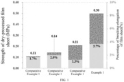
- FIG. 1 is a graph comparing tensile strengths of dry-processed negative electrode sheets obtained in Example 1 and Comparative Examples 1-3. It can be seen from the graph that the tensile strength and percentage of breaking-elongation of the sheets obtained without the addition of other binders in combination with the main binder and with the addition of a single binder in combination with the main binder were lower than those of the sheet obtained with the aqueous binder in combination with the dispersion binder according to the present disclosure.
- FIG. 2 is a graph of charging-discharging tests after the dry-processed negative sheets obtained in Example 1 and Comparative Examples 1-3 are assembled into cells. It can be seen from the graph that side reactions at the low voltage during discharging of the sheets obtained without the addition of other binders in combination with the main binder and with the addition of a single binder in combination with the main binder were higher than those of the sheet obtained with the aqueous binder in combination with the dispersion binder according to the present disclosure.
- Example 1 Item Initial Efficiency (%) 0.2C positive electrode gram capacity (mAh ⁇ g -1 ) Example 1 90.5 142.3 Example 2 89.5 141.5 Example 3 88.7 141.2 Example 4 89.2 141.7 Example 5 89.6 141.0 Example 6 89.0 141.1 Example 7 85.2 132.6 Example 8 86.5 138.1 Example 9 87.4 140.2 Example 10 86.3 138.6 Example 11 84.3 129.5 Example 12 88.6 140.2 Example 13 89.2 140.9 Example 14 88.1 139.5 Example 15 86.4 138.2 Example 16 88.2 140.3 Example 17 85.2 132.5 Example 18 83.1 128.6 Example 19 81.5 121.3 Example 20 88.5 140.2 Comparative Example 1 84.7 116.2 Comparative Example 2 85.2 125.5 Comparative Example 3 86.5 132.1
- Example 1 From the comparison of Example 1 and Comparative Examples 1-3, it can be seen that the initial efficiency and exertion of the gram capacity of the cells obtained with the addition of only a single water-based binder or a dispersion binder were less effect than those of the cell obtained with the aqueous binder in combination with the dispersion binder; from the comparison of Examples 1 and Examples 4-7, it can be seen that the ratio of the aqueous binder to the dispersion binder may affect the initial efficiency and exertion of the gram capacity of the cells; it can be seen from the comparison of the Example 1 and the Examples 8-11 that the addition amount of the main binder PTFE had an effect on the gram capacity and the initial efficiency of the cells, the increase in the amount of the main binder PTFE excessively occupies the amount of the active material, and at this time, the improvement effect of the same amount of the aqueous binder and the dispersion binder on the incremental main binder was weakened; from the comparison of Example 1 and Examples 12
Landscapes
- Chemical & Material Sciences (AREA)
- Chemical Kinetics & Catalysis (AREA)
- Electrochemistry (AREA)
- General Chemical & Material Sciences (AREA)
- Engineering & Computer Science (AREA)
- Materials Engineering (AREA)
- Manufacturing & Machinery (AREA)
- Organic Chemistry (AREA)
- Inorganic Chemistry (AREA)
- Battery Electrode And Active Subsutance (AREA)
Abstract
Description
- The present disclosure relates to a technical field of batteries, and in particular to a method for manufacturing a dry-processed electrode and a resulting dry-processed electrode and use thereof.
- Thanks to economic globalization and ever-increasing requirements for carbon neutrality and environmental protection of various countries around the world, replacing traditional energy sources with new energy sources has become a strong development trend. Lithium ion batteries are increasingly indispensable in fields of power and energy storage, and have become the main force in a field of new energy sources.
- With rapid development of lithium-ion battery technology and significant increase in market proportion, development of lithium-ion power batteries is increasingly moving towards low-cost, high-energy density, and fast charging technology. In terms of battery manufacturing, more attention is paid to resource costs, energy consumption, and recovery of volatile solvents. In terms of improving the energy density performance of the product, more attention is paid to thick electrode manufacturing and initial efficiency performance, and in terms of improving the rapid charging and power of the product, more attention is paid to rate characteristic of the battery.
- For a manufacturing process of lithium battery cells, key performances of the cells are mainly determined by a manufacturing process of an electrode sheet. In the related art, the manufacturing methods of the electrode sheet are mainly classified as wet process (or slurry-based/solution process) and dry process (or solvent-free process), and the wet process is the mainstream. In the wet process, a binder, a solvent, and a conductive agent are generally prepared into a conductive slurry, and then the active substance is added in portions to stir, and finally the solvent is added to adjust the viscosity of the slurry. However, in a conventional wet process, dispersion of the conductive agent is poor. At the same solid content, the viscosity of the slurry is higher than that of the dry process, and internal resistance of the manufactured battery electrode sheet is also larger.
- The dry-processed electrode technology is a new manufacturing process different from the wet method, basically does not use or uses a small amount of harmless solvent, and can increase compaction and manufacture a thick electrode, the dry-processed battery may increase energy density by more than 20%, and has more excellent kinetic characteristics, and in the thick electrode, cycle performance, impedance, and the like are preferable, so that the battery manufacturing cost and energy consumption may be greatly reduced, and battery performance may be greatly improved.
- In the related art, a more feasible dry manufacturing process uses a fibrillizable PTFE binder, for example, PTFE, SP, and graphite are mixed and stirred, to obtain a premix; premix fibrillization, in which the premix is subjected to fibrillization treatment to obtain a fibrillized mixture; baking the mixture, and baking the fibrillized mixture to obtain a cotton candy-like mixture; the mixture is formed into a film, and the cotton candy-like mixture is repeatedly folded and subjected to multiple rolling treatments to obtain a thicker film sheet; a film sheet thinning process for thinning the thicker film sheet to obtain a negative electrode film sheet conforming to requirements for the thickness; the dry film-forming preparation process of the negative electrode and the negative electrode dry film have advantages of simple process, less waste of materials, and low labor and material cost, and may improve production efficiency and production performance.
- For another example, a dry-processed electrode film is prepared by uniformly mixing an active material, a conductive agent, and a PTFE polymer film to obtain a mixture, performing fibrillization treatment to obtain a mixture, and then performing heating and rolling (or calendering) treatment. This method can greatly reduce the process difficulty of dry preparation of the electrode sheet by using a polymer film, and has low requirements for equipment used for the fibrillization, the fibrillization is more complete, and dispersion uniformity among components is better.
- However, there is a problem that the PTFE binder is not tolerant in the negative electrode, and the C-F bond may react with lithium during charging, thereby consuming part of the lithium ions and reducing the initial efficiency of the battery, which resulting in capacity loss. Research in the related art mainly carries out PTFE modification or uses other binders to improve this problem. However, PTFE modification is mainly based on addition of fluorine-containing monomers to copolymerize with tetrafluoroethylene, and the side reaction of C-F bond with lithium is still present. Among other binders, the most commonly used are polymers with low melting points, such as PP, PE, etc. When the active material is melted and bonded under the temperature close to the melting point, the process is complicated, and the produced electrode sheet has a large thickness and poor flexibility.
- In the production of the negative electrode sheet, it is easier to realize mass production through the dry process using the fibrillization of PTFE, and then large-scale industrialization is carried out. Therefore, in the dry-processed electrode technology, it is of great significance for improving the electric performance of the dry battery to study an electrode formulation and a corresponding new process, realize the PTFE modification in the electrode or the improvement of the surrounding environment, reduce the side reactions to improve the actual initial efficiency, and simultaneously improve falling off of active particles existing during a charging and discharging process under the pure PTFE process.
- In a first aspect, embodiments of the present disclosure provide a method of manufacturing an electrode, the method includes the steps of: formulating a dispersion binder and an aqueous binder into a glue liquid; dry-mixing an active material, a conductive agent, and a main binder to obtain a first dry material; adding the glue liquid to the first dry material for dispersion, and performing a drying treatment to obtain a second dry material; pulverizing the second dry material to form a binder-fibrillized powder; and pressing the powder to obtain a dry-processed electrode. The step of formulating the dispersion binder and the aqueous binder into the glue liquid and the step of dry-mixing the active material, the conductive agent and the main binder to obtain the first dry material are in a non-sequential order.
- In a second aspect, an embodiment of the present disclosure provides a dry-processed electrode obtained using the method according to the first aspect.
- In a third aspect, an embodiment of the present disclosure provides a battery including the dry-processed electrode according to the second aspect.
- The present disclosure provides following advantageous effects: in the manufacturing of the dry-processed electrode, the dispersion binder and the aqueous binder are used in combination with the main binder, so that the fibrillized main binder can be cladded, the surrounding environment of the main binder can be significantly improved, and further, the main binder can be protected from being reduced during charging, thereby solving the problem of low initial efficiency due to side reactions thereof, and improving the initial efficiency of the dry-processed electrode significantly; at the same time, the formulated binder formulation may improve the bonding effect between the active particles and between the active particles and the conductive agent, and can supplement the problem of insufficient bonding of the main binder of the network structure to the powder particles, thereby improving the quality of the film, improving the phenomenon of powder loss of the film, and improving cycle and other electrical properties of the cell.
- The binder used in the present disclosure has a simple formula, and the method of manufacturing electrode sheet is short in time and low in energy consumption, which is beneficial to reducing cost and improving production efficiency. Compared with the dry process using only the main adhesive, the film and the electrode sheet obtained in the present disclosure have no sign of powder loss at the same compaction density, the strength of the film sheet is obviously improved, and the initial effect and cycle stability of the cell after assembly of the electrode sheets are effectively improved.
-
-
FIG. 1 is a graph illustrating comparison between tensile strengths of dry-processed negative sheets obtained in Example 1 and Comparative Examples 1-3; -
FIG. 2 is a graph illustrating charging-discharging tests after the dry-processed negative sheets obtained in Example 1 and Comparative Examples 1-3 are assembled into cells. - The present disclosure provides a method of manufacturing an electrode including following steps:
- S1 a dispersion binder and an aqueous binder are prepared into a glue liquid;
- S2 an active material, a conductive agent, and a main binder are dry-mixed to obtain a first dry material;
- S3 the glue liquid is added to the first dry material for dispersing, and drying to obtain a second dry material;
- S4 the second dry material is pulverized to form a powder of a fibrillization binder;
- S5 the powder is pressed to obtain a dry-processed electrode;
- Among the above steps, the
step S 1 and the step S2 are in no particular order. - The purpose of the present disclosure is to provide a binder formulation for improving PTFE for dry-processed electrode fabrication and a process for electrode sheet processing using the formulation. It has been found in the present disclosure that a dispersion binder, in particular a small-molecule polymer binder such as PVP, is mixed with an aqueous binder to form a mixed glue liquid, and the mixed glue liquid is added to the fibrillized powder, can coat fibres of the main binder, such as PTFE fibres, and can significantly improve surrounding environment of the PTFE. Further, in the charging process, PTFE can be protected from being reduced, so that the problem of the low initial efficiency caused by the PTFE side reaction is solved, and the initial efficiency of the dry-processed system is significantly improved. At the same time, the mixed binders can bond the active particles to each other, and the active particles and the conductive agent to each other, which improves the problem of insufficient adhesion between the PTFE network structure and the powder particles, thereby improving the quality of the film sheet, improving the phenomenon of powder falling off the film sheet, and improving the cycle and other electrical properties of cells.
- The binder used in the present disclosure has a simple formula, and the method of manufacturing the electrode sheet is short in time and low in energy consumption, which is beneficial to reducing cost and improving production efficiency. Compared with the dry process using only the main binder, the film layer and the electrode sheet obtained in the present disclosure have no signs of powder falling at the same compaction density, the strength of the film sheet is obviously improved, and the initial efficiency and cycle stability of the cells obtained after assembly of the electrode sheets are effectively improved.
- The technical objects and advantageous effects of the present disclosure may be better achieved and realized by the following technical solutions, which may be the preferred technical solutions of the present disclosure, but are not the limitation of the technical solutions provided by the present disclosure.
- As a preferred solution of the present disclosure, the process is carried out in a production environment at a temperature of 20 to 35°C and a humidity of 40% RH- to 60% RH.
- As a preferred solution of the present disclosure, the dispersion binder includes a small-molecule polymer binder.
- Preferably, the small-molecule polymer binder includes any one or a combination of at least two of PVP (polyvinylpyrrolidone, e.g., K15, K30, K60, or K90), P123 (polyethylene oxide-polypropylene oxide-polyethylene oxide triblock copolymer), or PEG (polyethylene glycol), and typical but non-limiting examples of the combinations include a combination of the PVP and the P123, a combination of the PVP and the PEG, or a combination of the P123 and the PEG.
- Preferably, the aqueous binder includes any one or a combination of at least two of a polyacrylic acid (PAA) or a salt thereof or a copolymer thereof, a carboxymethyl cellulose (CMC) or a salt thereof or a copolymer thereof, an alginate, SBR emulsion, or PEG, typical but non-limiting examples of the combinations include a combination of the polyacrylic acid and the salt thereof or the copolymer thereof, a combination of the carboxymethyl cellulose and the salt thereof or the copolymer thereof, a combination of the polyacrylic acid and the alginate, a combination of the polyacrylic acid and the SBR emulsion, a combination of the polyacrylic acid and the PEG, a combination of the carboxymethyl cellulose and the alginate, a combination of the carboxymethyl cellulose and the SBR emulsion, a combination of the carboxymethyl cellulose and the PEG, a combination of the alginate and the SBR emulsion, a combination of the SBR emulsion and the PEG, or a combination of the PEG and the alginate.
- As a preferred embodiment of the present disclosure, a mass ratio of the dispersion binder to the aqueous binder in the glue liquid is (1 to 3): 1, such as 1:1, 1.2:1, 1.8:1, 2: 1, 2.4:1, 2.6:1, 3: 1, or the like, but is not limited to the values enumerated above, and other values not enumerated within the above range of values are equally applicable.
- In the present disclosure, the excessive amount of the dispersion binder may lead to the formation of thicker binder films on surfaces of main material particles, which affects exertion of the gram capacity and reduces the energy density of the battery. The effect of improving the electrochemical environment of the main binder on the negative electrode is poor when the amount of the dispersion binder is too low.
- Preferably, a total mass concentration of the binder in the glue liquid is 5wt% to 30wt%, such as 5wt%, 7wt%, 9wt%, 11wt%, 13wt%, 15wt%, 17wt%, 19wt%, 21wt%, 23wt%, 25wt%, 27wt%, 29wt%, 30wt%, or the like, but is not limited to the values enumerated above, and other values not enumerated within the above range of values are equally applicable.
- Preferably, in the method of preparing the glue liquid, firstly, the dispersion binder and the aqueous binder are respectively prepared into a liquid A and a liquid B, each of which has a mass concentration of 5wt% to 30wt%, such as 5wt%, 7wt%, 9wt%, 11wt%, 13wt%, 15wt%, 17wt%, 19wt%, 21wt%, 23wt%, 25wt%, 27wt%, 29wt%, 30wt%, or the like, and then, the liquid A and the liquid B are mixed with each other, and the mass concentration is adjusted to be 5wt% to 30wt% by a solvent, such as 5wt%, 7wt%, 9wt%, 11wt%, 13wt%, 15wt%, 17wt%, 19wt%, 21wt%, 23wt%, 25wt%, 27wt%, 29wt%, 30wt%, or the like, to obtain the glue liquid. However, the mass concentration is not limited to the values enumerated above, and other values not enumerated within the above range of values are equally applicable.
- Preferably, the solvent includes water.
- As a preferred embodiment of the present disclosure, the main binder includes polytetrafluoroethylene (PTFE) and/or polytetrafluoroethylene derivative.
- Preferably, the polytetrafluoroethylene derivative includes any one or a combination of at least two of tetrafluoroethylene to hexafluoropropylene copolymer (FEP), ethylene-tetrafluoroethylene copolymer (ETFE), or tetrafluoroethylene-perfluoroalkyl vinyl ether copolymer (PFA), and typical but non-limiting examples of the combination include a combination of the tetrafluoroethylene-hexafluoropropylene copolymer and the ethylene-tetrafluoroethylene copolymer, a combination of the tetrafluoroethylene-perfluoroalkyl vinyl ether copolymer and the tetrafluoroethylene-hexafluoropropylene copolymer, or a combination of the ethylene-tetrafluoroethylene copolymer and the tetrafluoroethylene-perfluoroalkyl vinyl ether copolymer.
- Preferably, the conductive agent includes any one or a combination of at least two of conductive carbon black (SP), carbon nanofiber (VGCF), carbon nanotubes (CNTs), or graphene, and typical but non-limiting examples of the conductive agent include a combination of the conductive carbon black and the carbon nanofibers, a combination of the conductive carbon black and the carbon nanotubes, a combination of the conductive carbon black and the graphene, a combination of the carbon nanofibers and the carbon nanotubes, a combination of the carbon nanofibers and the graphene, or a combination of the carbon nanotubes and the graphene.
- Preferably, when the dry-processed electrode is a negative electrode, the active material includes any one or a combination of at least two of graphite (natural graphite and/or artificial graphite), a silicon-carbon composite, or a silicon-oxygen composite, and typical but non-limiting examples of the active material include a combination of the graphite and the silicon-carbon composite, a combination of the graphite and the silicon-oxygen composite, or a combination of the silicon-carbon composite and the silicon-oxygen composite.
- As a preferred solution of the present disclosure, in the method of dry-mixing, a first mixing is firstly performed at a first dry-mixing rotate speed, and then a second mixing is performed at a second dry-mixing rotate speed higher than the first dry-mixing rotate speed.
- Preferably, the dry-mixing is carried out in a high speed-mixer with a cutter and a scraper.
- Preferably, under the first dry-mixing rotate speed, a rotate speed of the cutter is 1000 rpm to 30000 rpm, such as 1000 rpm, 3000 rpm, 5000 rpm, 7000 rpm, 9000 rpm, 12000 rpm, 15000 rpm, 18000 rpm, 21000 rpm, 25000 rpm, 27000 rpm, 30000 rpm, or the like, and a rotate speed of the scraper is 50 rpm to 1000 rpm, such as 50 rpm, 100 rpm, 200 rpm, 300 rpm, 400 rpm, 500 rpm, 600 rpm, 700 rpm, 800 rpm, 900 rpm, 1000 rpm, or the like. However, the rotate speeds are not limited to the values enumerated above, and other values not enumerated within the above range of values are equally applicable.
- Preferably, under the second dry-mixing speed, a rotate speed of the cutter is 1500 rpm to 30000 rpm, such as 1500 rpm, 3000 rpm, 5000 rpm, 7000 rpm, 9000 rpm, 12000 rpm, 15000 rpm, 18000 rpm, 21000 rpm, 25000 rpm, 27000 rpm, 30000 rpm, or the like, and a rotate speed of the scraper is 50 rpm to 1000 rpm, such as 50 rpm, 100 rpm, 200 rpm, 300 rpm, 400 rpm, 500 rpm, 600 rpm, 700 rpm, 800 rpm, 900 rpm, 1000 rpm, or the like. However, the rotate speeds are not limited to the values enumerated above, and other values not enumerated within the above range of values are equally applicable.
- Preferably, the duration of the first mixing is 1 min to 60 min, such as 1 min, 5 min, 10 min, 15 min, 20 min, 25 min, 30 min, 35 min, 40 min, 45 min, 50 min, 55 min, 60 min, or the like, but not limited to the values enumerated above, and other values not enumerated within the above range of values are equally applicable.
- Preferably, the duration of the second mixing is 1 min to 60 min, such as 1 min, 5 min, 10 min, 15 min, 20 min, 25 min, 30 min, 35 min, 40 min, 45 min, 50 min, 55 min, 60 min, or the like, but not limited to the values enumerated above, and other values not enumerated within the above range of values are equally applicable.
- Preferably, after the dry-mixing, a sieving is carried out to obtain a first dry material of 8 mesh to 50 mesh, such as 8 mesh, 11 mesh, 14 mesh, 17 mesh, 20 mesh, 23 mesh, 26 mesh, 29 mesh, 32 mesh, 35 mesh, 38 mesh, 41 mesh, 44 mesh, 47 mesh, 50 mesh, or the like, but not limited to the values enumerated above, and other values not enumerated within the above range of values are equally applicable.
- Preferably, the dry-mixing is carried out in a high-speed mixer.
- As a preferred technical solution of the present disclosure, the glue liquid is added to the first dry material for dispersion so that the solid content of the system is 70wt% to 90wt%, such as 70wt%, 72wt%, 74wt%, 76wt%, 78wt%, 80wt%, 82wt%, 84wt%, 86wt%, 88wt%, 90wt%, or the like, and a ratio of a mass of the main binder in the first dry material to a total mass of the dispersion binder and the aqueous binder in the glue liquid is controlled to be (0.5 to 3): 1, such as 0.5:1, 0.7:1, 0.9:1, 1.1:1, 1.3:1, 1.5:1, 1.7:1, 1.9:1, 2.1:1, 2.3:1, 2.5:1, 2.7:1, or 3: 1, but not limited to the values enumerated above, and other values not enumerated within the above range of values are equally applicable.
- Preferably, the drying is performed in a temperature of 0°C to 120°C, such as 0°C, 10°C, 20°C, 30°C, 40°C, 50°C, 60°C, 70°C, 80°C, 90°C, 100°C, 1 10°C, 120°C, or the like, and the drying is performed for a time of 2 h (hour) to 24 h, such as 2 h, 4 h, 6 h, 8 h, 10 h, 12 h, 14 h, 16 h, 18 h, 20 h, 22 h, 24 h, or the like. However, the drying temperature and the drying time are not limited to the values enumerated above, and other values not enumerated within the above range of values are equally applicable.
- Preferably, the second dry material has a particle size of 8 mesh to 40 mesh, such as 8 mesh, 11 mesh, 14 mesh, 17 mesh, 20 mesh, 23 mesh, 26 mesh, 29 mesh, 32 mesh, 35 mesh, 38 mesh, 41 mesh, 44 mesh, 47 mesh, 50 mesh, or the like.. However, the particle size is not limited to the values enumerated above, and other values not enumerated within the above range of values are equally applicable.
- Preferably, on the basis that the mass of the second dry material is 100wt%, the mass of the active substance is calculated to be 92wt% to 96wt%, such as 92wt%, 92.2wt%, 92.4wt%, 92.6wt%, 92.8wt%, 93wt%, 93.2wt%, 93.4wt%, 93.6wt%, 93.8wt%, 94wt%, 94.2wt%, 94.4wt%, 94.6wt%, 94.8wt%, 95wt%, 95.2wt%, 95.4wt%, 95.6wt%, 95.8wt%, 96wt%, or the like, but it is not limited to the values enumerated above, and other values not enumerated within the above range of values are equally applicable.
- Preferably, on the basis that the mass of the second dry material is 100wt%, the mass of the conductive agent is calculated to be 0.5wt% to 1.5wt%, such as 0.5wt%, 0.6wt%, 0.7wt%, 0.8wt%, 0.9wt%, 1wt%, 1.1wt%, 1.2wt%, 1.3wt%, 1.4wt%, 1.5wt%, or the like, but it is not limited to the values enumerated above, and other values not enumerated within the above range of values are equally applicable.
- Preferably, on the basis that the mass of the second dry material is 100wt%, the total mass of the binders is calculated to be 2.5wt% to 8.5wt%, such as 2.5wt%, 2.7wt%, 2.9wt%, 3.1wt%, 3.3wt%, 3.5wt%, 3.7wt%, 3.9wt%, 4.1wt%, 4.3wt%, 4.5wt%, 4.7wt%, 4.9wt%, 5.1wt%, 5.3wt%, 5.5wt%, 5.7wt%, 5.9wt%, 6.1wt%, 6.3wt%, 6.5wt%, 6.7wt%, 6.9wt%, 7.1wt%, 7.3wt%, 7.5wt%, 7.7wt%, 7.9wt%, 8.1wt%, 8.3wt%, 8.5wt%, or the like, but it is not limited to the values enumerated above, and other values not enumerated within the above range of values are equally applicable.
- Preferably, in the second dry material, the mass ratio of the main binder, the dispersion binder, and the aqueous binder is (1 to 12):(1 to 3):1, such as 1:1:1, 1:2:1, 1:3:1, 2:1:1, 2:2:1, 2:3:1, 3:1:1, 3:2:1, 3:3:1, 4:1:1, 4:2:1, 4:3:1, 5:1:1, 5:2:1, 5:3:1, 6:1:1, 6:2:1, 6:3:1, 7:1:1, 7:2:1, 7:3:1, 8:1:1, 8:2:1, 8:3:1, 9:1:1, 9:2:1, 9:3:1, 10:1:1, 10:2:1, 10:3:1, 11:1:1, 11:2:1, 11:3:1, 12:1:1, 12:2:1, 12:3:1, or the like, but it is not limited to the values enumerated above, and other values not enumerated within the above range of values are equally applicable.
- Preferably, on the basis that the mass of the second dry material is 100wt%, the mass of the main binder is 1wt% to 5wt%, such as 1wt%, 1.2wt%, 1.4wt%, 1.6wt%, 1.8wt%, 2wt%, 2.2wt%, 2.4wt%, 2.6wt%, 2.8wt%, 3wt%, 3.2wt%, 3.4wt%, 3.6wt%, 3.8wt%, 4wt%, 4.2wt%, 4.4wt%, 4.6wt%, 4.8wt%, 5wt%, or the like, but it is not limited to the values enumerated above, and other values not enumerated within the above range of values are equally applicable.
- Preferably, on the basis that the mass of the second dry material is 100wt%, the mass of the dispersion binder is 1wt% to 1.5wt%, such as 1wt%, 1.1wt%, 1.2wt%, 1.3wt%, 1.4wt%, 1.5wt%, or the like, but it is not limited to the values enumerated above, and other values not enumerated within the above range of values are equally applicable.
- Preferably, on the basis that the mass of the second dry material is 100wt%, the mass of the aqueous binder is 0.5wt% to 1wt%, such as 0.5wt%, 0.6wt%, 0.7wt%, 0.8wt%, 0.9wt%, 1wt%, or the like, but it is not limited to the values enumerated above, and other values not enumerated within the above range of values are equally applicable.
- As a preferred embodiment of the present disclosure, the pulverization is carried out in a pulverizer and/or a high-speed pulverizer.
- Preferably, the pulverization is carried out at a rotate speed of 1500 rpm to 30000 rpm, such as 1500 rpm, 3000 rpm, 5000 rpm, 7500 rpm, 10000 rpm, 12500 rpm, 15000 rpm, 17500 rpm, 20000 rpm, 22500 rpm, 25000 rpm, 27500 rpm, 30000 rpm, or the like, but it is not limited to the values enumerated above, and other values not enumerated within the above range of values are equally applicable.
- Preferably, the powder has a particle size of 35 mesh to 200 mesh, such as 35 mesh, 50 mesh, 75 mesh, 100 mesh, 125 mesh, 150 mesh, 175 mesh, 200 mesh, or the like, but it is not limited to the values enumerated above, and other values not enumerated within the above range of values are equally applicable.
- In the method of the present disclosure, the particle size of the powder after the fibrillization of the first dry material, the second dry material, and the binder needs to be controlled so as to prevent the formation of particles having a large amount of glue due to the large particle size, which is not conducive to dispersion.
- Preferably, the method of pressing includes a rolling method.
- As a preferred solution of the present disclosure, the method includes the following steps.
- At a step S1, a dispersion binder and an aqueous binder are respectively prepared into a liquid A and a liquid B, each of which has a mass concentration of 5wt% to 30wt%, using solvent water, the liquid A and the liquid B are mixed with each other, the mass ratio of the dispersion binder to the aqueous binder is controlled to be (1 to 3):1, and the mass concentration of the binder is adjusted to 5 to 30wt% using solvent water to obtain a glue liquid. The dispersion binder is a small-molecule polymer binder.
- At a step S2, the negative electrode active material, the conductive agent and the main binder are dry-mixed in a high-speed mixer, a first mixing is firstly performed at a first dry-mixing speed, a second mixing is performed at a second dry-mixing speed higher than the first dry-mixing speed, and then a sieving is carried out to obtain a first dry material of 8 mesh to 50 mesh. The main binder includes polytetrafluoroethylene and/or polytetrafluoroethylene derivatives.
- At a step S3, the glue liquid is added to the first dry material for dispersion so that the solid content of the system is 70wt% to 90wt%, a ratio of the mass of the main binder in the first dry material to the total mass of the dispersion binder and the aqueous binder in the glue liquid is controlled to be (0.5 to 3):1, and a drying treatment is performed to obtain a second dry material having a particle size of 8 mesh to 40 mesh. On the basis that the mass of the second dry material is 100wt%, the mass of the active material is 92wt% to 96wt%, the mass of the conductive agent is 0.5wt% to 1.5wt%, the mass of the main binder is 1wt% to 5wt%, the mass of the dispersion binder is 1wt% to 1.5wt%, and the mass of the aqueous binder is 0.5wt% to 1wt%. In the second dry material, the mass ratio of the main binder, the dispersion binder, and the aqueous binder is (1 to 12):(1 to 3):1.
- At a step S4, the second dry material is pulverized in a pulverizer and/or a high-speed pulverizer at 1500 rpm to 30000 rpm to form a binder-fibrillized powder, and the powder has a particle size of 35 mesh to 200 mesh.
- At a step S5, the powder is calendered using a roller press to obtain a dry-processed negative electrode.
- The step S1 and the step S2 are not in sequence.
- The present disclosure provides a dry-processed electrode obtained using the method described in the first aspect.
- The present disclosure provides a battery including the dry-processed electrode according to the second aspect.
- This example provides a method of manufacturing a dry-processed negative electrode, the method includes following steps.
- At a step S1, a dispersion binder and an aqueous binder were prepared into a glue liquid.
- At a step S2, an active substance, a conductive agent, and a main binder were dry-mixed to obtain a first dry material.
- At a step S3, the glue liquid was added to the first dry material for dispersion, and a drying treatment was performed to obtain a second dry material.
- At a step S4, the second dry material was pulverized to form a binder-fibrillized powder.
- At a step S5, the powder was calendered to obtain a dry-processed electrode.
- In this method, the step S1 and the step S2 are not in sequence.
- Specifically, the step S1 includes: firstly, a dispersion binder PEG and an aqueous binder CMC were respectively prepared into a liquid A and a liquid B, each of which has a mass concentration of 17wt%, using solvent water; and then the liquid A and the liquid B were mixed, the mass ratio of the dispersion binder to the aqueous binder was controlled to be 1.5:1, and the mass concentration was adjusted to 17wt% using solvent water to obtain a glue liquid. The dispersion binder was a small-molecule polymer binder.
- The step S2 includes: graphite (G) as the negative electrode active material, conductive carbon black (SP) as the conductive agent and polytetrafluoroethylene (PTFE) as the main binder were dry-mixed in a high-speed mixer, a first mixing was performed at a first dry-mixing speed, a second mixing was performed at a second dry-mixing speed higher than the first dry-mixing speed, and a sieving was carried out to obtain a first dry material of 20 mesh.
- The step S3 includes: the glue liquid was added to the first dry material for dispersion so that the solid content of the system was 80wt% and the ratio of the mass of the main binder in the first dry material to the total mass of the dispersion binder and the aqueous binder in the glue liquid was controlled to be 2:1, and a second dry material having a particle size of 30 mesh was obtained after drying. On the basis that the mass of the second dry material was 100wt%, the mass of the active material was 96wt%, the mass of the conductive agent was 1wt%, the mass of the main binder was 2wt%, the mass of the dispersion binder was 0.6wt%, and the mass of the aqueous binder was 0.4wt%. In the second dry material, the mass ratio of the main binder, the dispersion binder, and the aqueous binder was 5:1.5:1.
- The step S4 includes: the second dry material was placed in a pulverizer and/or a high-speed pulverizer, and was pulverized at 20000 rpm to form a binder-fibrillized powder. The powder had a particle size of 60 mesh;
The step S5 includes: the powder was calendered using a roller press to obtain a dry-processed negative electrode. - This example provides a method of manufacturing a dry-processed negative electrode, the method includes following steps.
- At a step S1, a dispersion binder PVP and an aqueous binder PAA were respectively prepared into a liquid A and a liquid B, each of which has a mass concentration of 5wt%, using solvent water, and then the liquid A and the liquid B were mixed, the mass ratio of the dispersion binder to the aqueous binder was controlled to be 3: 1, and the mass concentration was adjusted to 5wt% using solvent water to obtain a glue liquid. The dispersion binder was a small-molecule polymer binder.
- At a step S2, carbon-coated silicon particles as the negative electrode active material, carbon nanotubes as the conductive agent and tetrafluoroethylene-hexafluoropropylene copolymer (FEP) as the main binder were dry-mixed in a high-speed mixer, a first mixing was performed at a first dry-mixing speed, a second mixing was performed at a second dry-mixing speed higher than the first dry-mixing speed, and a sieving was carried out to obtain a first dry material of 8 mesh.
- At a step S3, the glue liquid was added to the first dry material for dispersion so that the solid content of the system was 70wt% and the ratio of the mass of the main binder in the first dry material to the total mass of the dispersion binder and the aqueous binder in the glue liquid was controlled to be 2.75:1, and a second dry material having a particle size of 8 mesh was obtained after drying. On the basis that the mass of the second dry material was 100wt%, the mass of the active material was 92wt%, the mass of the conductive agent was 0.5wt%, the mass of the main binder was 5.5wt%, the mass of the dispersion binder was 1.5wt%, and the mass of the aqueous binder was 0.5wt%. In the second dry material, the mass ratio of the main binder, the dispersion binder, and the aqueous binder was 11:3:1.
- At a step S4, the second dry material was placed in a pulverizer and/or a high-speed pulverizer, and was pulverized at 1500 rpm to form a binder-fibrillized powder. The powder had a particle size of 200 mesh.
- At a step S5, the powder was calendered using a roller press to obtain a dry-processed negative electrode.
- This example provides a method of manufacturing a dry-processed negative electrode, the method includes following steps.
- At a step S1, a dispersion binder P123 and an aqueous binder SBR were respectively prepared into a liquid A and a liquid B, each of which has a mass concentration of 30wt%, using solvent water, and then the liquid A and the liquid B were mixed, the mass ratio of the dispersion binder to the aqueous binder was controlled to be 3: 1, and the mass concentration was adjusted to 30wt% using solvent water to obtain a glue liquid. The dispersion binder was a small-molecule polymer binder;
- At a step S2, carbon-coated silicon particles as the negative electrode active material, carbon nanotubes as the conductive agent and ethylene-tetrafluoroethylene copolymer (ETFE) as the main binder were dry-mixed in a high-speed mixer, a first mixing was performed at a first dry-mixing speed, a second mixing was performed at a second dry-mixing speed higher than the first dry-mixing speed, and a sieving was carried out to obtain a first dry material of 50 mesh.
- At a step S3, the glue liquid was added to the first dry material for dispersion so that the solid content of the system was 90wt% and the ratio of the mass of the main binder in the first dry material to the total mass of the dispersion binder and the aqueous binder in the glue liquid was controlled to be 0.5:1, and a second dry material having a particle size of 40 mesh was obtained after drying. On the basis that the mass of the second dry material was 100wt%, the mass of the active material was 95.5wt%, the mass of the conductive agent was 1.5wt%, the mass of the main binder was 1wt%, the mass of the dispersion binder was 1.5wt%, and the mass of the aqueous binder was 0.5wt%. In the second dry material, the mass ratio of the main binder, the dispersion binder, and the aqueous binder was 2:3:1;
- At a step S4, P the second dry material was placed in a pulverizer and/or a high-speed pulverizer, and was pulverized at 30000 rpm to form a binder-fibrillized powder. The powder had a particle size of 35 mesh;
- At a step S5, the powder was calendered using a roller press to obtain a dry-processed negative electrode.
- This example provides a method of manufacturing a dry-processed negative electrode, this example is similar to Example 1 except that in the step S1, the mass ratio of a dispersion binder to an aqueous binder was adjusted from 1.5:1 to 4:1, so that in the step S3, the mass of the dispersion binder was adjusted from 0.6wt% to 0.8wt%, the mass of the aqueous binder was adjusted from 0.4wt% to 0.2wt%, and the mass ratio of the main binder, the dispersion binder, and the aqueous binder is changed from 5:1.5:1 to 10:4:1.
- This example provides a method of manufacturing a dry-processed negative electrode, this example is similar to Example 1 except that in the step S1, the mass ratio of a dispersion binder to an aqueous binder was adjusted from 1.5:1 to 3:1, so that in the step S3, the mass of the dispersion binder was adjusted from 0.6wt% to 0.75wt%, the mass of the aqueous binder was adjusted from 0.4wt% to 0.25wt%, and the mass ratio of the main binder, the dispersion binder, and the aqueous binder was changed from 5:1.5:1 to 8:3:1.
- This example provides a method of manufacturing a dry-processed negative electrode, this example is similar to Example 1 except that in the step S1, the mass ratio of a dispersion binder to an aqueous binder was adjusted from 1.5:1 to 0.5:1, so that in the step S3, the mass of the dispersion binder was adjusted from 0.6wt% to 0.33wt%, the mass of the aqueous binder was adjusted from 0.4wt% to 0.66wt%, and the mass ratio of the main binder, the dispersion binder, and the aqueous binder is changed from 5:1.5:1 to 3:0.5:1.
- This example provides a method of manufacturing a dry-processed negative electrode, this example is similar to Example 1 except that in the step S1, the mass ratio of a dispersion binder to an aqueous binder was adjusted from 1.5:1 to 0.33:1, so that in the step S3, the mass of the dispersion binder was adjusted from 0.6wt% to 0.25wt%, the mass of the aqueous binder was adjusted from 0.4wt% to 0.66wt%, and the mass ratio of the main binder, the dispersion binder, and the aqueous binder was changed from 5:1.5:1 to 2.67:0.33:1.
- This example provides a method of manufacturing a dry-processed negative electrode, this example is similar to Example 1 except that in the step S2, the amount of a main binder was adjusted so that in the step S3, the ratio of the mass of the main binder to the total mass of the dispersion binder and the aqueous binder in the glue liquid was adjusted from 2: 1 to 0.5:1, and in the step S3, the mass of the active material was adjusted from 96wt% to 97.5wt% and the mass of the main binder was adjusted from 2wt% to 0.5wt%, so that the mass ratio of the main binder, the dispersion binder, and the aqueous binder was changed from 5:1.5:1 to 1.25:1.5:1.
- This example provides a method of manufacturing a dry-processed negative electrode, this example is similar to Example 1 except that in the step S2, the amount of a main binder was adjusted so that in the step S3, the ratio of the mass of the main binder to the total mass of the dispersion binder and the aqueous binder in the glue liquid was adjusted from 2: 1 to 1:1, and in the step S3, the mass of the active material was adjusted from 96wt% to 97wt% and the mass of the main binder was adjusted from 2wt% to 1wt%, so that the mass ratio of the main binder, the dispersion binder, and the aqueous binder was changed from 5:1.5:1 to 2.5:1.5:1.
- This example provides a method of manufacturing a dry-processed negative electrode, this example is similar to Example 1 except that in the step S2, the amount of a main binder was adjusted so that in the step S3, the ratio of the mass of the main binder to the total mass of the dispersion binder and the aqueous binder in the glue liquid was adjusted from 2: 1 to 3:1, and in the step S3, the mass of the active material was adjusted from 96wt% to 95wt% and the mass of the main binder was adjusted from 2wt% to 3wt%, so that the mass ratio of the main binder, the dispersion binder, and the aqueous binder was changed from 5:1.5:1 to 7.5:1.5:1.
- This example provides a method of manufacturing a dry-processed negative electrode, this example is similar to Example 1 except that in the step S2, the amount of a main binder was adjusted so that in the step S3, the ratio of the mass of the main binder to the total mass of the dispersion binder and the aqueous binder in the glue liquid was adjusted from 2: 1 to 4: 1, and in the step S3, the mass of the active material was adjusted from 96wt% to 94wt% and the mass of the main binder was adjusted from 2wt% to 4wt%, so that the mass ratio of the main binder, the dispersion binder, and the aqueous binder was changed from 5:1.5:1 to 10:1.5:1.
- This example provides a method of manufacturing a dry-processed negative electrode, this example is similar to Example 1 except that in the step S2, a particle size of a second dry material was adjusted from 30 mesh to 5 mesh.
- This example provides a method of manufacturing a dry-processed negative electrode, this example is similar to Example 1 except that in the step S2, a particle size of a second dry material was adjusted from 30 mesh to 8 mesh.
- This example provides a method of manufacturing a dry-processed negative electrode, this example is similar to Example 1 except that in the step S2, a particle size of a second dry material was adjusted from 30 mesh to 40 mesh.
- This example provides a method of manufacturing a dry-processed negative electrode, this example is similar to Example 1 except that in the step S2, a particle size of a second dry material was adjusted from 30 mesh to 45 mesh.
- This example provides a method of manufacturing a dry-processed negative electrode, this example is similar to Example 1 except that in the step S4, a particle size of powder was adjusted from 60 mesh to 35 mesh.
- This example provides a method of manufacturing a dry-processed negative electrode, this example is similar to Example 1 except that in the step S(4), a particle size of powder was adjusted from 60 mesh to 100 mesh.
- This example provides a method of manufacturing a dry-processed negative electrode, this example is similar to Example 1 except that in the step S4, a particle size of powder was adjusted from 60 mesh to 200 mesh.
- This example provides a method of manufacturing a dry-processed negative electrode, this example is similar to Example 1 except that in the step S4, a particle size of powder was adjusted from 60 mesh to 210 mesh.
- This example provides a method of manufacturing a dry-processed negative electrode, this example is similar to Example 1 except that in the step S1, CMC was replaced with PEG as an aqueous binder so that the dispersion binder is identical to the aqueous binder.
- The present comparative example provides a method of manufacturing a dry-processed negative electrode without using a dispersion binder and an aqueous binder, that is, this example is similar to Example 1 except that in the step S1 of this method, the dispersion binder and the aqueous binder were replaced with an equal amount of a main binder and the main binder was prepared into a glue liquid for subsequent steps.
- The present comparative example provides a method of manufacturing a dry-processed negative electrode without using an aqueous binder, that is, this example is similar to Example 1 except that in the step S1 of this method, the aqueous binder was replaced with an equal amount of a main binder, and the main binder and the dispersion binder were prepared into a glue liquid for subsequent steps.
- The present comparative example provides a method of manufacturing a dry-processed negative electrode without using a dispersion binder, that is, this example is similar to Example 1 except that in the step S1 of this method, the dispersion binder was replaced with an equal amount of a main binder, and the main binder and the aqueous binder were prepared into a glue liquid for subsequent steps.
- The dry-processed negative electrode sheets obtained in the examples and the comparative examples were assembled into cells CR-2025 (negative electrode half-cell), and the cells were tested using a Xinwei battery test cabinet for initial charging/discharging performance, cycle performance, or the like;
-
FIG. 1 is a graph comparing tensile strengths of dry-processed negative electrode sheets obtained in Example 1 and Comparative Examples 1-3. It can be seen from the graph that the tensile strength and percentage of breaking-elongation of the sheets obtained without the addition of other binders in combination with the main binder and with the addition of a single binder in combination with the main binder were lower than those of the sheet obtained with the aqueous binder in combination with the dispersion binder according to the present disclosure. -
FIG. 2 is a graph of charging-discharging tests after the dry-processed negative sheets obtained in Example 1 and Comparative Examples 1-3 are assembled into cells. It can be seen from the graph that side reactions at the low voltage during discharging of the sheets obtained without the addition of other binders in combination with the main binder and with the addition of a single binder in combination with the main binder were higher than those of the sheet obtained with the aqueous binder in combination with the dispersion binder according to the present disclosure. - Results of other examples and comparative examples are shown in Table 1.
Table 1 Item Initial Efficiency (%) 0.2C positive electrode gram capacity (mAh·g-1) Example 1 90.5 142.3 Example 2 89.5 141.5 Example 3 88.7 141.2 Example 4 89.2 141.7 Example 5 89.6 141.0 Example 6 89.0 141.1 Example 7 85.2 132.6 Example 8 86.5 138.1 Example 9 87.4 140.2 Example 10 86.3 138.6 Example 11 84.3 129.5 Example 12 88.6 140.2 Example 13 89.2 140.9 Example 14 88.1 139.5 Example 15 86.4 138.2 Example 16 88.2 140.3 Example 17 85.2 132.5 Example 18 83.1 128.6 Example 19 81.5 121.3 Example 20 88.5 140.2 Comparative Example 1 84.7 116.2 Comparative Example 2 85.2 125.5 Comparative Example 3 86.5 132.1 - It can be seen from Table 1:
From the comparison of Example 1 and Comparative Examples 1-3, it can be seen that the initial efficiency and exertion of the gram capacity of the cells obtained with the addition of only a single water-based binder or a dispersion binder were less effect than those of the cell obtained with the aqueous binder in combination with the dispersion binder; from the comparison of Examples 1 and Examples 4-7, it can be seen that the ratio of the aqueous binder to the dispersion binder may affect the initial efficiency and exertion of the gram capacity of the cells; it can be seen from the comparison of the Example 1 and the Examples 8-11 that the addition amount of the main binder PTFE had an effect on the gram capacity and the initial efficiency of the cells, the increase in the amount of the main binder PTFE excessively occupies the amount of the active material, and at this time, the improvement effect of the same amount of the aqueous binder and the dispersion binder on the incremental main binder was weakened; from the comparison of Example 1 and Examples 12 to 15, it can be seen that when the particle size of the second dry material dispersed by adding the glue liquid is too large, the dispersion effect may be affected, and thus the performance of the sheets were slightly affected; from the comparison of Example 1 and Examples 16-19, it can be seen that the particle size of the binder-fibrillized powder finally obtained was very important, and when the particle size was large, the performance of the sheets was degraded; from comparison of Example 1 and Example 20, when both the aqueous binder and the dispersion binder were small molecule polymer PEG, the gram capacity and the initial efficiency of the cells were affected, and the effect was inferior to that of Example 1.
Claims (15)
- A method of manufacturing a dry-processed electrode, characterized by comprising steps of:formulating a dispersion binder and an aqueous binder into a glue liquid;dry-mixing an active material, a conductive agent, and a main binder to obtain a first dry material;adding the glue liquid to the first dry material for dispersion, and performing a drying treatment to obtain a second dry material;pulverizing the second dry material to form a binder-fibrillized powder; andpressing the powder to obtain a dry-processed electrode;wherein the step of formulating the dispersion binder and the aqueous binder into the glue liquid and the step of dry-mixing the active material, the conductive agent and the main binder to obtain the first dry material are in a non-sequential order.
- The method of claim 1, characterized in that the dispersion binder comprises a small molecule polymer binder;preferably, the small molecule polymer binder comprises any one or a combination of at least two of PVP, P123 or PEG; andpreferably, the aqueous binder comprises any one or a combination of at least two of a polyacrylic acid or a salt of the polyacrylic acid or a copolymer of the polyacrylic acid, carboxymethyl cellulose or a salt of the carboxymethyl cellulose or a copolymer of the carboxymethyl cellulose, an alginate, an SBR emulsion, or PEG.
- The method of claim 1 or 2, characterized in that a mass ratio of the dispersion binder to the aqueous binder in the glue liquid is (1 to 3): 1;preferably, a total mass concentration of binders in the glue liquid is 5wt% to 30wt%;preferably, the step for formulating the dispersion binder and the aqueous binder into the glue liquid comprises: formulating the dispersion binder and the aqueous binder into a liquid A and a liquid B respectively, each having a mass concentration of 5wt% to 30wt%; and mixing the liquid A and the liquid B, and adjusting the mass concentration to 5wt% to 30wt% using a solvent to obtain the glue liquid; and preferably, the solvent comprises water.
- The method of any one of claims 1 to 3, characterized in that the main binder comprises polytetrafluoroethylene and/or polytetrafluoroethylene derivative;preferably, the polytetrafluoroethylene derivative comprises any one or a combination of at least two of a tetrafluoroethylene-hexafluoropropylene copolymer, an ethylene-tetrafluoroethylene copolymer, or a tetrafluoroethylene-perfluoroalkyl vinyl ether copolymer;preferably, the conductive agent comprises any one or a combination of at least two of conductive carbon black, carbon nanofibers, carbon nanotubes, or graphene;preferably, when the dry-processed electrode is a negative electrode, the active material comprises any one or a combination of at least two of graphite, silicon-carbon composite or silicon-oxygen composite.
- The method of any one of claims 1 to 4, characterized in that the step of dry-mixing the active material, the conductive agent, and the main binder to obtain the first dry material comprises: performing a first mixing at a first dry-mixing rotate speed firstly; and then performing a second mixing at a second dry-mixing rotate speed higher than the first dry-mixing rotate speed;preferably, the dry-mixing is carried out in a high-speed mixer with a cutter and a scraper;preferably, under the first dry-mixing rotate speed, a rotate speed of the cutter is 1000 rpm to 30000 rpm, and a rotate speed of the scraper is 50 rpm to 1000 rpm;preferably, under the second dry-mixing rotate speed, a rotate speed of the cutter is 1500 rpm to 30000 rpm, and a rotate speed of the scraper is 50 rpm to 1000 rpm;preferably, a duration of the first mixing is 1 min to 60 min;preferably, a duration of the second mixing is 1 min to 60 min; andpreferably, after the dry-mixing, a sieving is performed to obtain a first dry material of 8 mesh to 50 mesh.
- The method of any one of claims 1 to 5, characterized in that the glue liquid is added to the first dry material for dispersion so that a solid content of system is 70wt% to 90wt%, and a ratio of a mass of the main binder in the first dry material to a total mass of the dispersion binder and the aqueous binder in the glue liquid is controlled to be (0.5 to 3):1;preferably, a temperature of the drying treatment is 0°C to 120°C, and a duration of the drying treatment is 2 h to 24 h;preferably, the second dry material has a particle size of 8 mesh to 40 mesh;preferably, on a basis that a mass of the second dry material is 100wt%, a mass of the active material is 92wt% to 96wt%;preferably, on a basis that a mass of the second dry material is 100wt%, a mass of the conductive agent is 0.5wt% to 1.5wt%;preferably, on a basis that a mass of the second dry material is 100wt%, a total mass of binders is 2.5wt% to 8.5wt%;preferably, in the second dry material, a mass ratio of the main binder, the dispersion binder, and the aqueous binder is (1 to 12):(1 to 3):1;preferably, on a basis that a mass of the second dry material is 100wt%, a mass of the main binder is 1wt% to 6wt%;preferably, on a basis that a mass of the second dry material is 100wt%, a mass of the dispersion binder is 1wt% to 1.5wt%; andpreferably, on a basis that a mass of the second dry material is 100wt%, a mass of the aqueous binder is 0.5wt%to 1wt%.
- The method of any one of claims 1 to 6, characterized in that the step of pulverizing the second dry material is carried out in a pulverizer and/or a high-speed pulverizer;preferably, the step of pulverizing the second dry material is carried out at a rotate speed of 1500 rpm to 30000 rpm;preferably, the powder has a particle size of 35 mesh to 200 mesh; andpreferably, a method of pressing comprises rolling.
- The method of any one of claims 1 to 7, characterized in that the step of formulating the dispersion binder and the aqueous binder into the glue liquid comprises: formulating the dispersion binder and the aqueous binder into a liquid A and a liquid B, each having a mass concentration of 5wt% to 30wt%, using solvent water; and then mixing the liquid A and the liquid B, controlling a mass ratio of the dispersion binder to the aqueous binder to be (1 to 3): 1, and adjusting the mass concentration to be 5wt% to 30wt% using solvent water to obtain the glue liquid; and the dispersion binder is a small molecule polymer binder;the step of dry-mixing the active material, the conductive agent, and the main binder to obtain the first dry material comprises: dry-mixing the negative electrode active material, the conductive agent, and the main binder in a high-speed mixer, performing a first mixing at a first dry-mixing rotate speed firstly, performing a second mixing at a second dry-mixing rotate speed higher than the first dry-mixing rotate speed, and performing a sieving to obtain a first dry material of 8 mesh to 50 mesh; the main binder comprises polytetrafluoroethylene and/or polytetrafluoroethylene derivative;the step of adding the glue liquid to the first dry material for dispersion, and performing the drying treatment to obtain the second dry material comprises: adding the glue liquid to the first dry material for dispersion so that a solid content of system is 70wt% to 90wt% and a ratio of a mass of the main binder in the first dry material to a total mass of the dispersion binder and the aqueous binder in the glue liquid is controlled to be (0.5 to 3): 1; and performing the drying treatment for 2 h to 24 h at 0°C to 120°C to obtain a second dry material with a particle size of 8 mesh to 40 mesh; on a basis that a mass of the second dry material is 100wt%, a mass of the active material is 92wt% to 96wt%, a mass of the conductive agent is 0.5wt% to 1.5wt%, a mass of the main binder is 1wt% to 6wt%, a mass of the dispersion binder is 1wt% to 1.5wt%, and a mass of the aqueous binder is 0.5wt% to 1wt%; in the second dry material, a mass ratio of the main binder, the dispersion binder and the aqueous binder is (1 to 12):(1 to 3): 1;the step of pulverizing the second dry material to form the binder-fibrillized powder comprises: pulverizing the second dry material in a pulverizer and/or a high-speed pulverizer at 1500 rpm to 30000 rpm to form the binder-fibrillized powder, the powder has a particle size of 35 mesh to 200 mesh;the step of pressing the powder to obtain the dry-processed electrode comprises calendering the powder using a roller press to obtain a dry-processed negative electrode.
- A dry-processed electrode characterized by being obtained using the method of any one of claims 1 to 8.
- The dry-processed electrode of claim 9, characterized in that the dispersion binder comprises a small molecule polymer binder;preferably, the small molecule polymer binder comprises any one or a combination of at least two of PVP, P123 or PEG; andpreferably, the aqueous binder comprises any one or a combination of at least two of a polyacrylic acid or a salt of the polyacrylic acid or a copolymer of the polyacrylic acid, carboxymethyl cellulose or a salt of the carboxymethyl cellulose or a copolymer of the carboxymethyl cellulose, an alginate, an SBR emulsion, or PEG.
- The dry-processed electrode of claim 9 or 10, characterized in that a mass ratio of the dispersion binder to the aqueous binder in the glue liquid is (1 to 3):1;preferably, a total mass concentration of binders in the glue liquid is 5wt% to 30wt%;preferably, the step for formulating the dispersion binder and the aqueous binder into the glue liquid comprises: formulating the dispersion binder and the aqueous binder into a liquid A and a liquid B respectively, each having a mass concentration of 5wt% to 30wt%; and mixing the liquid A and the liquid B, and adjusting the mass concentration to 5wt% to 30wt% using a solvent to obtain the glue liquid; and preferably, the solvent comprises water.
- The dry-processed electrode of any one of claims 9 to 11, characterized in that the main binder comprises polytetrafluoroethylene and/or polytetrafluoroethylene derivative;preferably, the polytetrafluoroethylene derivative comprises any one or a combination of at least two of a tetrafluoroethylene-hexafluoropropylene copolymer, an ethylene-tetrafluoroethylene copolymer, or a tetrafluoroethylene-perfluoroalkyl vinyl ether copolymer;preferably, the conductive agent comprises any one or a combination of at least two of conductive carbon black, carbon nanofibers, carbon nanotubes, or graphene;preferably, when the dry-processed electrode is a negative electrode, the active material comprises any one or a combination of at least two of graphite, silicon-carbon composite or silicon-oxygen composite.
- The dry-processed electrode of any one of claims 9 to 12, characterized in that the step of dry-mixing the active material, the conductive agent, and the main binder to obtain the first dry material comprises:performing a first mixing at a first dry-mixing rotate speed firstly; and then performing a second mixing at a second dry-mixing rotate speed higher than the first dry-mixing rotate speed;preferably, the dry-mixing is carried out in a high-speed mixer with a cutter and a scraper;preferably, under the first dry-mixing rotate speed, a rotate speed of the cutter is 1000 rpm to 30000 rpm, and a rotate speed of the scraper is 50 rpm to 1000 rpm;preferably, under the second dry-mixing rotate speed, a rotate speed of the cutter is 1500 rpm to 30000 rpm, and a rotate speed of the scraper is 50 rpm to 1000 rpm;preferably, a duration of the first mixing is 1 min to 60 min;preferably, a duration of the second mixing is 1 min to 60 min; andpreferably, after the dry-mixing, a sieving is performed to obtain a first dry material of 8 mesh to 50 mesh.
- The dry-processed electrode of any one of claims 9 to 13, characterized in that the glue liquid is added to the first dry material for dispersion so that a solid content of system is 70wt% to 90wt%, and a ratio of a mass of the main binder in the first dry material to a total mass of the dispersion binder and the aqueous binder in the glue liquid is controlled to be (0.5 to 3): 1;preferably, a temperature of the drying treatment is 0°C to 120°C, and a duration of the drying treatment is 2 h to 24 h;preferably, the second dry material has a particle size of 8 mesh to 40 mesh;preferably, on a basis that a mass of the second dry material is 100wt%, a mass of the active material is 92wt% to 96wt%;preferably, on a basis that a mass of the second dry material is 100wt%, a mass of the conductive agent is 0.5wt% to 1.5wt%;preferably, on a basis that a mass of the second dry material is 100wt%, a total mass of binders is 2.5wt% to 8.5wt%;preferably, in the second dry material, a mass ratio of the main binder, the dispersion binder, and the aqueous binder is (1 to 12):(1 to 3):1;preferably, on a basis that a mass of the second dry material is 100wt%, a mass of the main binder is 1wt% to 6wt%;preferably, on a basis that a mass of the second dry material is 100wt%, a mass of the dispersion binder is 1wt% to 1.5wt%; andpreferably, on a basis that a mass of the second dry material is 100wt%, a mass of the aqueous binder is 0.5wt%to 1wt%.
- A battery characterized by comprising the dry-processed electrode of claims 9 to 14.
Applications Claiming Priority (2)
| Application Number | Priority Date | Filing Date | Title |
|---|---|---|---|
| CN202310886118.8A CN116960285A (en) | 2023-07-19 | 2023-07-19 | A method for preparing dry electrodes and the obtained dry electrodes and their uses |
| PCT/CN2023/137300 WO2025015816A1 (en) | 2023-07-19 | 2023-12-07 | Method for preparing dry electrode, and dry electrode obtained therefrom and use thereof |
Publications (2)
| Publication Number | Publication Date |
|---|---|
| EP4496021A1 true EP4496021A1 (en) | 2025-01-22 |
| EP4496021B1 EP4496021B1 (en) | 2026-05-13 |
Family
ID=88457746
Family Applications (1)
| Application Number | Title | Priority Date | Filing Date |
|---|---|---|---|
| EP24189817.0A Active EP4496021B1 (en) | 2023-07-19 | 2024-07-19 | Method of manufacturing dry-processed electrode and obtained dry-processed electrode |
Country Status (4)
| Country | Link |
|---|---|
| EP (1) | EP4496021B1 (en) |
| CN (1) | CN116960285A (en) |
| ES (1) | ES3072487T3 (en) |
| WO (1) | WO2025015816A1 (en) |
Families Citing this family (4)
| Publication number | Priority date | Publication date | Assignee | Title |
|---|---|---|---|---|
| CN116960285A (en) * | 2023-07-19 | 2023-10-27 | 惠州亿纬锂能股份有限公司 | A method for preparing dry electrodes and the obtained dry electrodes and their uses |
| CN117497684B (en) * | 2023-10-30 | 2026-06-09 | 惠州亿纬锂能股份有限公司 | Fibrous fluffy powder and preparation method thereof and lithium ion battery |
| KR20250117203A (en) * | 2024-01-26 | 2025-08-04 | 삼성에스디아이 주식회사 | Method and apparatus for manufacturing active material particle for dry electrode |
| WO2025179476A1 (en) * | 2024-02-28 | 2025-09-04 | Guangdong Haozhi Technology Co. Limited | Binder composition for secondary battery |
Citations (3)
| Publication number | Priority date | Publication date | Assignee | Title |
|---|---|---|---|---|
| US20090224198A1 (en) * | 2005-05-26 | 2009-09-10 | Hidekazu Mori | Electrode material for electrochemical element and composite particle |
| US20230106377A1 (en) * | 2021-10-01 | 2023-04-06 | Licap Technologies, Inc. | Dry electrode manufacture for solid state energy storage devices |
| CN116457172A (en) * | 2020-11-18 | 2023-07-18 | 蓝界科技控股公司 | Method for producing self-supporting electrode film in wet process without organic solvent |
Family Cites Families (15)
| Publication number | Priority date | Publication date | Assignee | Title |
|---|---|---|---|---|
| EP3609000B1 (en) * | 2017-04-28 | 2023-05-03 | LG Energy Solution, Ltd. | Cathode, secondary battery comprising same, and method for manufacturing same cathode |
| WO2020139823A1 (en) * | 2018-12-23 | 2020-07-02 | Worcester Polytechnic Institute | Adhesive interlayer for battery electrode through dry manufacturing |
| WO2020197673A1 (en) * | 2019-03-22 | 2020-10-01 | Cabot Corporation | Cathode electrode compositions for battery applications |
| US12040474B2 (en) * | 2020-11-13 | 2024-07-16 | Licap Technologies, Inc. | Dry electrode manufacture with composite binder |
| CN113659104A (en) * | 2021-08-11 | 2021-11-16 | 蜂巢能源科技(无锡)有限公司 | Method for preparing battery active layer, battery pole piece and application |
| CN113764205B (en) * | 2021-09-02 | 2023-05-30 | 惠州亿纬锂能股份有限公司 | Carbon electrode and preparation method and application thereof |
| CN113871566B (en) * | 2021-09-18 | 2023-06-23 | 苏州清陶新能源科技有限公司 | A kind of dry process electrode membrane, its preparation method and application |
| CN114156431B (en) * | 2021-11-30 | 2023-06-16 | 蜂巢能源科技有限公司 | Positive electrode homogenizing method, positive electrode slurry and application thereof |
| CN115763811B (en) * | 2022-11-29 | 2025-09-23 | 楚能新能源股份有限公司 | Negative electrode sheet, preparation method thereof, and lithium-ion battery |
| CN115939392A (en) * | 2022-12-01 | 2023-04-07 | 惠州亿纬锂能股份有限公司 | A kind of negative electrode slurry and preparation method thereof and lithium ion battery |
| CN115722093B (en) * | 2022-12-07 | 2025-08-29 | 惠州亿纬锂能股份有限公司 | Aqueous homogenization process, slurry and lithium battery for lithium-ion battery positive electrode system |
| CN116014082A (en) * | 2022-12-30 | 2023-04-25 | 天津市捷威动力工业有限公司 | Dry pole piece, preparation method and lithium ion battery |
| CN116031360B (en) * | 2022-12-30 | 2024-09-24 | 湖北亿纬动力有限公司 | Mixing method of dry battery materials and preparation method of dry electrode membrane |
| CN116190571B (en) * | 2023-03-21 | 2026-05-08 | 深圳市研一新材料有限责任公司 | A dry electrode sheet, its preparation method and application |
| CN116960285A (en) * | 2023-07-19 | 2023-10-27 | 惠州亿纬锂能股份有限公司 | A method for preparing dry electrodes and the obtained dry electrodes and their uses |
-
2023
- 2023-07-19 CN CN202310886118.8A patent/CN116960285A/en active Pending
- 2023-12-07 WO PCT/CN2023/137300 patent/WO2025015816A1/en not_active Ceased
-
2024
- 2024-07-19 ES ES24189817T patent/ES3072487T3/en active Active
- 2024-07-19 EP EP24189817.0A patent/EP4496021B1/en active Active
Patent Citations (3)
| Publication number | Priority date | Publication date | Assignee | Title |
|---|---|---|---|---|
| US20090224198A1 (en) * | 2005-05-26 | 2009-09-10 | Hidekazu Mori | Electrode material for electrochemical element and composite particle |
| CN116457172A (en) * | 2020-11-18 | 2023-07-18 | 蓝界科技控股公司 | Method for producing self-supporting electrode film in wet process without organic solvent |
| US20230106377A1 (en) * | 2021-10-01 | 2023-04-06 | Licap Technologies, Inc. | Dry electrode manufacture for solid state energy storage devices |
Also Published As
| Publication number | Publication date |
|---|---|
| WO2025015816A1 (en) | 2025-01-23 |
| EP4496021B1 (en) | 2026-05-13 |
| ES3072487T3 (en) | 2026-07-02 |
| CN116960285A (en) | 2023-10-27 |
Similar Documents
| Publication | Publication Date | Title |
|---|---|---|
| EP4496021B1 (en) | Method of manufacturing dry-processed electrode and obtained dry-processed electrode | |
| EP2343757A1 (en) | Electrode for lead storage battery and lead storage battery | |
| CN111509231B (en) | Negative electrode slurry, negative electrode sheet and preparation method thereof | |
| CN105406070A (en) | Preparation method of lithium ion battery positive pole size | |
| CN113078317A (en) | Water-based conductive adhesive for lithium ion battery and preparation method thereof | |
| CN116936735A (en) | Dry electrode film with low binder content, preparation method and application thereof | |
| CN111834623A (en) | Homogenizing method of lithium ion battery silicon-based negative electrode slurry | |
| CN111697225A (en) | Lithium iron phosphate anode slurry for lithium ion battery, preparation method of lithium iron phosphate anode slurry and anode plate | |
| EP4116355A1 (en) | Composite polymer, and preparation method therefor and application thereof | |
| CN111554937A (en) | Negative electrode slurry, negative electrode sheet and preparation method thereof | |
| CN113851609A (en) | Silicon-based negative electrode plate and preparation method thereof, and all-solid-state lithium ion battery | |
| JP2023512026A (en) | Electrode formulation for Li-ion batteries and method for producing solvent-free electrodes | |
| CN115566179B (en) | A high energy density lithium ion battery silicon-based negative electrode composite slurry and preparation method thereof | |
| CN114156431A (en) | Positive electrode homogenizing method, positive electrode slurry and application thereof | |
| CN115548244A (en) | A kind of pulping process of sodium ion battery cathode slurry | |
| CN110459738A (en) | Lithium ion battery anode glue size and preparation method thereof, positive plate, lithium ion battery | |
| CN112072064A (en) | Method for improving stability and dispersibility of lithium ion battery cathode slurry | |
| US12431504B2 (en) | Silicon-based negative electrode slurry, preparation method therefor, and negative electrode piece | |
| CN119108493A (en) | A method for preparing negative electrode slurry, negative electrode sheet and battery | |
| CN113839009A (en) | A negative electrode slurry and preparation method thereof, negative electrode sheet and secondary battery | |
| CN116014136A (en) | Preparation method of binder, composition, slurry and pole piece for battery cathode | |
| CN120998934A (en) | Positive electrode sheet and its preparation method and lithium-ion battery | |
| CN109411758A (en) | A kind of preparation method of negative electrode of lithium ion battery water system electroconductive binder | |
| CN113921760A (en) | Thick graphite electrode and preparation method thereof | |
| TW202124272A (en) | Composite graphene conductive agent, method for preparing conductive paste with high conductivity by using the same and lithium battery prepared therefrom including carbon black, carbon nanotubes and graphene which are in the mass ratio of (1 to 4):(0.5 to 4.5):(1 to 3.5) |
Legal Events
| Date | Code | Title | Description |
|---|---|---|---|
| PUAI | Public reference made under article 153(3) epc to a published international application that has entered the european phase |
Free format text: ORIGINAL CODE: 0009012 |
|
| STAA | Information on the status of an ep patent application or granted ep patent |
Free format text: STATUS: REQUEST FOR EXAMINATION WAS MADE |
|
| 17P | Request for examination filed |
Effective date: 20240719 |
|
| AK | Designated contracting states |
Kind code of ref document: A1 Designated state(s): AL AT BE BG CH CY CZ DE DK EE ES FI FR GB GR HR HU IE IS IT LI LT LU LV MC ME MK MT NL NO PL PT RO RS SE SI SK SM TR |
|
| GRAP | Despatch of communication of intention to grant a patent |
Free format text: ORIGINAL CODE: EPIDOSNIGR1 |
|
| STAA | Information on the status of an ep patent application or granted ep patent |
Free format text: STATUS: GRANT OF PATENT IS INTENDED |
|
| RIC1 | Information provided on ipc code assigned before grant |
Ipc: H01M 4/04 20060101AFI20251220BHEP Ipc: C09J 9/02 20060101ALI20251220BHEP Ipc: C09J 127/18 20060101ALI20251220BHEP Ipc: H01M 4/133 20100101ALI20251220BHEP Ipc: H01M 4/134 20100101ALI20251220BHEP Ipc: H01M 4/1393 20100101ALI20251220BHEP Ipc: H01M 4/38 20060101ALI20251220BHEP Ipc: H01M 4/62 20060101ALI20251220BHEP Ipc: H01M 4/583 20100101ALI20251220BHEP Ipc: H01M 4/1395 20100101ALN20251220BHEP Ipc: H01M 10/0525 20100101ALN20251220BHEP Ipc: H01M 4/02 20060101ALN20251220BHEP Ipc: C08F 120/06 20060101ALN20251220BHEP |
|
| INTG | Intention to grant announced |
Effective date: 20260126 |
|
| GRAS | Grant fee paid |
Free format text: ORIGINAL CODE: EPIDOSNIGR3 |
|
| GRAA | (expected) grant |
Free format text: ORIGINAL CODE: 0009210 |
|
| STAA | Information on the status of an ep patent application or granted ep patent |
Free format text: STATUS: THE PATENT HAS BEEN GRANTED |
|
| AK | Designated contracting states |
Kind code of ref document: B1 Designated state(s): AL AT BE BG CH CY CZ DE DK EE ES FI FR GB GR HR HU IE IS IT LI LT LU LV MC ME MK MT NL NO PL PT RO RS SE SI SK SM TR |
|
| REG | Reference to a national code |
Ref country code: CH Ref legal event code: F10 Free format text: ST27 STATUS EVENT CODE: U-0-0-F10-F00 (AS PROVIDED BY THE NATIONAL OFFICE) Effective date: 20260513 Ref country code: GB Ref legal event code: FG4D |
|
| P01 | Opt-out of the competence of the unified patent court (upc) registered |
Free format text: CASE NUMBER: UPC_APP_0013086_4496021/2026 Effective date: 20260417 |
|
| REG | Reference to a national code |
Ref country code: DE Ref legal event code: R096 Ref document number: 602024004677 Country of ref document: DE Ref country code: IE Ref legal event code: FG4D |
|
| REG | Reference to a national code |
Ref country code: ES Ref legal event code: FG2A Ref document number: 3072487 Country of ref document: ES Kind code of ref document: T3 Effective date: 20260702 |