EP4495971A1 - Electronic device - Google Patents
Electronic device Download PDFInfo
- Publication number
- EP4495971A1 EP4495971A1 EP23770191.7A EP23770191A EP4495971A1 EP 4495971 A1 EP4495971 A1 EP 4495971A1 EP 23770191 A EP23770191 A EP 23770191A EP 4495971 A1 EP4495971 A1 EP 4495971A1
- Authority
- EP
- European Patent Office
- Prior art keywords
- housing
- key
- keytop
- end side
- rubber
- Prior art date
- Legal status (The legal status is an assumption and is not a legal conclusion. Google has not performed a legal analysis and makes no representation as to the accuracy of the status listed.)
- Pending
Links
Images



Classifications
-
- H—ELECTRICITY
- H05—ELECTRIC TECHNIQUES NOT OTHERWISE PROVIDED FOR
- H05K—PRINTED CIRCUITS; CASINGS OR CONSTRUCTIONAL DETAILS OF ELECTRIC APPARATUS; MANUFACTURE OF ASSEMBLAGES OF ELECTRICAL COMPONENTS
- H05K5/00—Casings, cabinets or drawers for electric apparatus
- H05K5/0017—Casings, cabinets or drawers for electric apparatus with operator interface units
-
- G—PHYSICS
- G06—COMPUTING OR CALCULATING; COUNTING
- G06F—ELECTRIC DIGITAL DATA PROCESSING
- G06F15/00—Digital computers in general; Data processing equipment in general
- G06F15/02—Digital computers in general; Data processing equipment in general manually operated with input through keyboard and computation using a built-in program, e.g. pocket calculators
- G06F15/0225—User interface arrangements, e.g. keyboard, display; Interfaces to other computer systems
-
- G—PHYSICS
- G06—COMPUTING OR CALCULATING; COUNTING
- G06F—ELECTRIC DIGITAL DATA PROCESSING
- G06F3/00—Input arrangements for transferring data to be processed into a form capable of being handled by the computer; Output arrangements for transferring data from processing unit to output unit, e.g. interface arrangements
- G06F3/01—Input arrangements or combined input and output arrangements for interaction between user and computer
- G06F3/02—Input arrangements using manually operated switches, e.g. using keyboards or dials
-
- G—PHYSICS
- G06—COMPUTING OR CALCULATING; COUNTING
- G06F—ELECTRIC DIGITAL DATA PROCESSING
- G06F3/00—Input arrangements for transferring data to be processed into a form capable of being handled by the computer; Output arrangements for transferring data from processing unit to output unit, e.g. interface arrangements
- G06F3/01—Input arrangements or combined input and output arrangements for interaction between user and computer
- G06F3/02—Input arrangements using manually operated switches, e.g. using keyboards or dials
- G06F3/0202—Constructional details or processes of manufacture of the input device
-
- G—PHYSICS
- G06—COMPUTING OR CALCULATING; COUNTING
- G06F—ELECTRIC DIGITAL DATA PROCESSING
- G06F3/00—Input arrangements for transferring data to be processed into a form capable of being handled by the computer; Output arrangements for transferring data from processing unit to output unit, e.g. interface arrangements
- G06F3/01—Input arrangements or combined input and output arrangements for interaction between user and computer
- G06F3/02—Input arrangements using manually operated switches, e.g. using keyboards or dials
- G06F3/0202—Constructional details or processes of manufacture of the input device
- G06F3/0216—Arrangements for ergonomically adjusting the disposition of keys of a keyboard
-
- H—ELECTRICITY
- H01—ELECTRIC ELEMENTS
- H01H—ELECTRIC SWITCHES; RELAYS; SELECTORS; EMERGENCY PROTECTIVE DEVICES
- H01H13/00—Switches having rectilinearly-movable operating part or parts adapted for pushing or pulling in one direction only, e.g. push-button switch
- H01H13/02—Details
- H01H13/12—Movable parts; Contacts mounted thereon
- H01H13/14—Operating parts, e.g. push-button
-
- H—ELECTRICITY
- H01—ELECTRIC ELEMENTS
- H01H—ELECTRIC SWITCHES; RELAYS; SELECTORS; EMERGENCY PROTECTIVE DEVICES
- H01H13/00—Switches having rectilinearly-movable operating part or parts adapted for pushing or pulling in one direction only, e.g. push-button switch
- H01H13/70—Switches having rectilinearly-movable operating part or parts adapted for pushing or pulling in one direction only, e.g. push-button switch having a plurality of operating members associated with different sets of contacts, e.g. keyboard
- H01H13/702—Switches having rectilinearly-movable operating part or parts adapted for pushing or pulling in one direction only, e.g. push-button switch having a plurality of operating members associated with different sets of contacts, e.g. keyboard with contacts carried by or formed from layers in a multilayer structure, e.g. membrane switches
- H01H13/705—Switches having rectilinearly-movable operating part or parts adapted for pushing or pulling in one direction only, e.g. push-button switch having a plurality of operating members associated with different sets of contacts, e.g. keyboard with contacts carried by or formed from layers in a multilayer structure, e.g. membrane switches characterised by construction, mounting or arrangement of operating parts, e.g. push-buttons or keys
-
- H—ELECTRICITY
- H01—ELECTRIC ELEMENTS
- H01H—ELECTRIC SWITCHES; RELAYS; SELECTORS; EMERGENCY PROTECTIVE DEVICES
- H01H13/00—Switches having rectilinearly-movable operating part or parts adapted for pushing or pulling in one direction only, e.g. push-button switch
- H01H13/70—Switches having rectilinearly-movable operating part or parts adapted for pushing or pulling in one direction only, e.g. push-button switch having a plurality of operating members associated with different sets of contacts, e.g. keyboard
- H01H13/702—Switches having rectilinearly-movable operating part or parts adapted for pushing or pulling in one direction only, e.g. push-button switch having a plurality of operating members associated with different sets of contacts, e.g. keyboard with contacts carried by or formed from layers in a multilayer structure, e.g. membrane switches
- H01H13/705—Switches having rectilinearly-movable operating part or parts adapted for pushing or pulling in one direction only, e.g. push-button switch having a plurality of operating members associated with different sets of contacts, e.g. keyboard with contacts carried by or formed from layers in a multilayer structure, e.g. membrane switches characterised by construction, mounting or arrangement of operating parts, e.g. push-buttons or keys
- H01H13/7065—Switches having rectilinearly-movable operating part or parts adapted for pushing or pulling in one direction only, e.g. push-button switch having a plurality of operating members associated with different sets of contacts, e.g. keyboard with contacts carried by or formed from layers in a multilayer structure, e.g. membrane switches characterised by construction, mounting or arrangement of operating parts, e.g. push-buttons or keys characterised by the mechanism between keys and layered keyboards
-
- H—ELECTRICITY
- H01—ELECTRIC ELEMENTS
- H01H—ELECTRIC SWITCHES; RELAYS; SELECTORS; EMERGENCY PROTECTIVE DEVICES
- H01H13/00—Switches having rectilinearly-movable operating part or parts adapted for pushing or pulling in one direction only, e.g. push-button switch
- H01H13/70—Switches having rectilinearly-movable operating part or parts adapted for pushing or pulling in one direction only, e.g. push-button switch having a plurality of operating members associated with different sets of contacts, e.g. keyboard
- H01H13/84—Switches having rectilinearly-movable operating part or parts adapted for pushing or pulling in one direction only, e.g. push-button switch having a plurality of operating members associated with different sets of contacts, e.g. keyboard characterised by ergonomic functions, e.g. for miniature keyboards; characterised by operational sensory functions, e.g. sound feedback
Definitions
- the present invention relates to an electronic device.
- an electronic device called a calculator is provided with a display and a key input section on the top of its housing.
- the key input section has multiple keys arranged in a matrix pattern.
- the key input section has numeric keys, arithmetic keys, function keys, etc., each including multiple keys.
- the electronic device is desired to be capable of enabling accurate and quick hitting of keys of the key input section, without easily causing fatigue even from use for a long time.
- a keyboard structure with stepped keys (a step sculpture) for mitigating a physical burden is known.
- Jpn. UM Appln. KOKAI Publication No. S60-141035 Japanese Utility Model Application No. S59-29404 , microfilm discloses a structure with keys having a height difference in which an elastic sheet for supporting the keys (push-button switches) has a shape deformed (flexed) according to the positions of the keys.
- a key-to-key deformation of the key-supporting elastic sheet in this manner alters the operability (a feel of a click) for each key and consequently causes a sense of discomfort in the user at key-depressing actions.
- the present invention has been formulated in view of such problems and its objects include providing an electronic device having multiple operation parts which entail reduced variations in operability even if differing in height from each other.
- an electronic device includes a plurality of operation parts arranged from a first-end side to a second-end side of a housing and each including a keytop member having an operation surface.
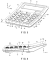
- FIGS. 1, 2 , 3, and 4 are diagrams showing external configurations of an electronic device 10 according to an embodiment.
- FIG. 1 is a plan view of the electronic device 10 according to the embodiment.
- FIG. 2 is a diagram of the electronic device 10 according to the embodiment, viewed from the lower-side-surface side.
- FIG. 3 is a perspective view of the electronic device 10 according to the embodiment.
- FIG. 4 is a diagram of the electronic device 10 according to the embodiment, viewed from the right-side-surface side.
- the electronic device 10 is provided with a key input section 11 and a display section 12 on the top surface of its housing.
- the key input section 11 has multiple keys 14, one or more selector switches 15, and so on.
- the multiple keys 14 include, for example, numeric keys, arithmetic keys, function keys, etc.
- the numeric keys include, for example, multiple keys corresponding to [00] and [0] to [9], respectively.
- the function keys include, for example, an all-clear key (an [AC] key), a clear key (a [C] key), multiple memory keys ([MRC], [M-], and [M+] keys), a root key (a [V] key), and a [%] key.
- the selector switch or switches 15 include, for example, a round selector and a decimal point selector.
- the housing top surface of the electronic device 10 is formed in a substantially rectangular outer shape.
- the housing top surface includes the display section 12 on an upper side (the upper-edge side of the housing top surface) and the key input section 11 on a lower side (the lower-edge side of the housing top surface).
- a display 16 is disposed on a first housing surface 12a which is a first region (the upper side) of the housing top surface.
- the display 16 has, for example, a horizontally long rectangular display surface and extends from a first-end side (the left-edge side in FIG. 1 ) of the housing to a second-end side (the right-edge side in FIG. 1 ) opposite the first-end side.
- multiple keys 14 are arranged from the first-end side to the second-end side of the housing and on a second housing surface 11a which is a second region (the lower side) of the housing top surface.
- the multiple keys 14 each have an operation surface 14t on their respective key tops.
- the multiple keys 14, in one example, are arranged at predetermined intervals (key pitches) in each of the row and column directions, with the row direction assumed to be a direction parallel to the upper edge/the lower edge of the housing top surface and the column direction assumed to be a direction parallel to the left edge/the right edge of the housing top surface.
- the second housing surface 11a of the key input section 11 is inclined in a direction from the first-end side to the second-end side, i.e., in the row direction of the arrangement of the multiple keys 14, at a first inclination angle (angle ⁇ ) with respect to the placement surface (the bottom surface of the housing).
- the first housing surface 12a for the display section 12 is substantially in parallel (or substantially horizontal) to the placement surface (the bottom surface of the housing), or is inclined in the direction from the first-end side to the second-end side, i.e., in the row direction of the arrangement of the multiple keys 14, at a second inclination angle different from the first inclination angle (angle ⁇ ) with respect to the bottom surface of the housing.
- the second housing surface 11a of the electronic device 10 is formed to be inclined in the row direction, in which the keys 14 are arranged, at the angle ⁇ with respect to the bottom surface 13 of the housing.
- the angle ⁇ be in a range of 1° to 9°. It is further preferred that the angle ⁇ be in a range of, for example, 1° to 3° (this will be described in more detail later).
- FIGS. 1 to 4 illustrate a configuration of the electronic device 10 which is an example where the second housing surface 11a of the key input section 11 has a rightward inclination (the left-edge side is higher than the right-edge side) as depicted in FIGS. 2 and 4 .
- the operation surface 14t of the key 14 (a first operation part) on the first-end side (the left-edge side) is formed to have a greater height from the placement surface (the bottom surface of the housing) than that of at least a portion of the operation surface 14t of the key 14 (a second operation part) on the second-end side (the right-edge side).
- the central portion (a first central portion) of the operation surface 14t of the key 14 arranged on the first-end side has a greater height from the placement surface (the bottom surface of the housing) than that of the central portion (a second central portion) of the operation surface 14t of the key 14 arranged on the second-end side.
- the second housing surface 11a of the key input section 11 has a leftward inclination.
- at least a portion of the operation surface 14t of the key 14 on the second-end side is formed to have a greater height from the placement surface (the bottom surface of the housing) than that of at least a portion of the operation surface 14t of the key 14 on the first-end side (the left-edge side).
- the display surface of the display section 12 is formed such that its portion on the first-end side has a height from the placement surface (the bottom surface of the housing) not greater than that of its portion on the second-end side.
- the first-end portion (the left-edge portion) and the second-end portion (the right-edge portion) of the display section 12 are aligned at the same height, and the upper-edge side of the housing top surface is raised from the boundary between the key input section 11 and the display section 12, so that the inclination in the column direction (the front-and-back direction) of the arrangement of the multiple keys 14 is formed.
- the housing of the electronic device 10 is bent at the boundary between the key input section 11 and the display section 12 so that the upper-edge side of the housing top surface is positioned higher. Accordingly, the first housing surface 12a of the display section 12 is inclined in the column direction in which the multiple keys 14 are arranged, thereby enhancing viewability of the display surface of the display 16.
- FIG. 5 is a diagram showing an exemplary cross-section taken along the line A-A shown in FIG. 1 .
- FIG. 5 only shows, among the multiple keys 14 arranged along the line A-A, two consecutively arranged keys 14. Illustrations in FIGS. 7 to 12 are given in a similar manner.
- FIGS. 5 and 7 to 12 discussed below involve deformations for facilitating the understanding of the configuration of the multiple keys 14 provided for the electronic device 10, and as such, they may not perfectly conform to the configurations shown in FIGS. 1 to 4 .
- a substrate 22 is provided at the bottom portion inside the housing of the electronic device 10, in a state parallel to the bottom surface 13 of the housing.
- the substrate 22 supports, inside the housing, the multiple keys 14.
- the keys 14 are constituted by, for example, a rubber key 21a, and key tops 14a1 and 14a2 (keytop members).
- the key tops 14a1 and 14a2 are formed of, for example, a resin.
- the rubber key 21a is placed on the upper surface of the substrate 22.
- the rubber key 21a is formed of, for example, an elastic material such as rubber.
- the rubber key 21a includes dome-shaped rubber key tops 21a1 and 21a2 (rubber members) formed at positions corresponding to the respective key tops 14a1 and 14a2 of the multiple keys 14.
- the rubber key tops 21a1 and 21a2 are constituted by respective attachment portions 21a11 and 21a22 to which the lower ends of the key tops 14a1 and 14a2 are attached, and respective support portions 21a12 and 21a22 which support the attachment portions 21a11 and 21a21 in a state separated from the substrate 24.
- the attachment portions 21a11 and 21a22 are supported by the support portions 21a12 and 21a22 so that they are normally separated from the substrate 24 but are pressed downward until they contact the substrate 24 at the time of a depressing action, in order to provide operability in response to a depressing action on the key tops 14a1 and 14a2 attached on the respective attachment portions 21a11 and 21a21.
- the rubber key tops 21a1 and 21a2 are standardized for providing the same operability (feel of a click) at depressing actions on the key tops 14a1 and 14a2.
- the rubber key tops 21a1 and 21a2 are formed from the same material (constituent), the same shape, and the same size to substantially equal each other in mass, etc.
- a "feel of a click” refers to a sense taken by the user upon recognizing a repulsion (an elastic force) produced by the rubber key top 21a1 or 21a2 squashed by the user's depressing action on the key top 14a1 or 14a2.
- FIG. 6 is a plan view showing an example of the rubber key 21a according to the embodiment.
- the rubber key 21a has multiple rubber key tops at positions coinciding with the multiple keys 14 arranged on the second housing surface 11a of the key input section 11 shown in FIG. 1 .
- the rubber key tops 21a1 and 21a2, to which the respective key tops 14a1 and 14a2 of the two keys arranged along the line A-A are attached, are included.
- the respectively corresponding key tops 14a1 and 14a2 are attached via the attachment portions 21a11 and 21a22 so that their key stroke directions (sliding directions) are made perpendicular to the bottom surface 13 of the housing (the placement surface of the housing).
- the rubber key tops 21a1 and 21a2 are each provided with a conductive member at their bottoms so that the rubber key tops 21a1 and 21a2 pressed downward by the depressing action on the key tops 14a1 and 14a2 will cause the conductive members to contact electrodes arranged on the substrate 22 for the detection of key depression events.
- the key tops 14a1 and 14a2 are formed to have mutually different heights, each being a height from the bottom surface (the lower end) to the operation surface, according to their arrangement positions in the area from the first-end side (the key top 14a1 side) to the second-end side (the key top 14a2 side).
- the second housing surface 11a of the key input section 11 is inclined to the right, and as such, a height Ta1 of the key top 14a1 arranged on the first-end side, i.e., the height from its bottom surface to operation surface 14ta1, is greater than a height Ta2 of the key top 14a2 arranged on the second-end side, i.e., the height from its bottom surface to operation surface 14ta2.
- the operation surfaces 14ta1 and 14ta2 are set at the same height from the inclined second housing surface 11a so that the heights of the operation surfaces 14ta1 and 14ta2 from the bottom surface 13 of the housing (the placement surface of the housing) show a stepped profile according to the inclination angle ⁇ of the second housing surface 11a.
- FIG. 5 shows only the two key tops 14a1 and 14a2
- the multiple key tops arranged from the first-end side to the second-end side are formed in a similar configuration to that of the key tops 14a1 and 14a2 so that the operation surfaces of the multiple key tops are stepped according to the inclination angle ⁇ .
- a constant height difference is set between operation surfaces of the multiple consecutive key tops.
- the second housing surface 11a (the housing top surface) has openings corresponding to the multiple keys 14, respectively.
- the openings are each formed in such a manner that the opening wall surface is substantially perpendicular (vertical) to the bottom surface 13 of the housing (the placement surface of the housing).
- the key tops 14a1 and 14a2 slidably pass through the corresponding openings, and their respective operation surfaces 14ta1 and 14ta2 are supported at levels higher than the second housing surface 11a in the normal state.
- the side surfaces of the key tops 14a1 and 14a2 each extend substantially in parallel to the opening wall surface of the corresponding opening and face this corresponding opening wall surface with a slight clearance therebetween.
- ribs 31a1 and 31a2 are formed to extend in the sliding direction of the key tops 14a1 and 14a2, i.e., the direction perpendicular to the bottom surface 13 of the housing (the placement surface of the housing), from the respective openings of the second housing surface 11a.
- the side surfaces of the ribs 31a1 and 31a2 facing the respective key tops 14a1 and 14a2 each extend substantially in parallel to the corresponding key top 14a1 or 14a2 and face the corresponding key top 14a1 or 14a2 with a slight clearance therebetween.
- the ribs 31a1 and 31a2 extending in the sliding direction of the key tops 14a1 and 14a2 from the respective openings, can prevent the key tops 14a1 and 14a2 from wobbling in such a manner as to keep them within the slight clearance during their sliding movement.
- the second housing surface 11a (the housing top surface) is inclined at the angle ⁇ , and the attachment portions 21a11 and 21a22 have the same height (at the same level) from the bottom surface 13 of the housing.
- the ribs 31a1 and 31a2 are each formed to have lengths from the back of the second housing surface 11a (the inner surface of the housing) to the position abutting the flanged bottom of the key top 14a1 or 14a2 (or to the contact position in the non-operating state) such that the length on the first-end side (the key top 14a1 side) is greater than the length on the second-end side (the key top 14a2 side).
- the ribs 31a1 and 31a2 have lengths varying in the sliding direction of the key tops 14a1 and 14a2 (the direction perpendicular to the bottom surface 13 of the housing) according to the heights of the key tops 14a1 and 14a2.
- the operation surfaces 14ta1 and 14ta2 (upper surfaces) of the key tops 14a1 and 14a2 are each formed to be in parallel to the bottom surface 13.
- the operation surfaces 14ta1 and 14ta2 of the key tops 14a1 and 14a2 are horizontal.
- heights L1 and L2 of the respective key tops 14a1 and 14a2 decrease in order from the key top 14a1 on the first-end side and the key top 14a2 on the second-end side.
- the key tops 14a1 and 14a2 are formed in an analogous shape with a comparable stroke length defined by the movable ranges of the rubber key tops 21a1 and 21a2, and therefore, the heights L1 and L2 from the bottom surface 13 show a stepped profile according to the inclination angle ⁇ of the second housing surface 11a as shown in FIGS. 2 and 3 .
- the second housing surface 11a of the key input section 11 is inclined in the row direction of the keys 14 at the angle ⁇ with respect to the bottom surface 13, and the operation surface 14t of the key 14 disposed on the first-end side is higher than the operation surface 14t of the key 14 disposed on the second-end side. This realizes good operability with the keys 14 and prevents the user from being easily fatigued.
- the rubber key 21a (the rubber key tops 21a1 and 21a2) has a standardized configuration (material / shape (mass)) for the multiple keys 14, while the key tops 14a1 and 14a2 have mutually different heights from their respective bottom surfaces to operation surfaces 14ta1 and 14ta2. This realizes reduced variations in operability while having different heights of the operation surfaces 14ta1 and 14ta2 of the key tops 14a1 and 14a2 from the bottom surface 13 of the housing.
- FIG. 7 is a diagram showing an exemplary cross-section taken along the line A-A shown in FIG. 1 .
- the second configuration example is basically similar to the first configuration example. More specifically, keys 14 are constituted by, for example, a rubber key 21b and key tops 14b1 and 14b2 (keytop members).
- the key tops 14b1 and 14b2 are formed of, for example, a resin.
- the rubber key 21b is placed on the upper surface of the substrate 22. Similar to the rubber key 21a described above, the rubber key 21b is formed of, for example, an elastic material such as rubber.
- the rubber key 21b includes dome-shaped rubber key tops 21b1 and 21b2 (rubber members) formed at positions corresponding to the respective key tops 14b1 and 14b2 of the multiple keys 14.
- the rubber key tops 21b1 and 21b2 are formed in a similar configuration to that of the rubber key tops 21a1 and 21a2 in the first configuration example ( FIG. 5 ). Also, the ribs 31b1 and 31b2 are formed in a similar configuration to that of the ribs 31a1 and 31a2 in the first configuration example ( FIG. 5 ).
- the key tops 14b1 and 14b2 are formed such that a height Tb1 of the key top 14b1 arranged on the first-end side, i.e., the height from its bottom surface to operation surface 14tb1, is greater than a height Tb2 of the key top 14b2 arranged on the second-end side, i.e., the height from its bottom surface to operation surface 14tb2.
- a hollowing-out amount from components is differentiated for each key.
- the key tops 14b1 and 14b2, as in the first configuration example, are formed to have mutually different heights, each being a height from the bottom surface to the operation surface, according to their arrangement positions in the area from the first-end side (the key top 14a1 side) to the second-end side (the key top 14a2 side), and the key top 14b1 on the first-end side has a greater height than the key top 14b2.
- the key top 14b1 has a greater mass.
- a greater hollowing-out amount is adopted for components having a greater height from the bottom surface to the operation surface so that the multiple key tops arranged in the area from the first-end side to the second-end side have substantially the same mass.
- the key top 14b1 is hollowed out with support members 41b1 left inside
- the key top 14b2 is hollowed out with more support members 41b2 left as compared to the key top 14b1.
- the masses of the key tops themselves i.e., the key tops 14b1 and 14b2
- the masses of the key tops themselves i.e., the key tops 14b1 and 14b2
- the masses of the key tops themselves can be made substantially equal to each other by adjusting the hollowed-out amounts from the key tops 14b1 and 14b2. Accordingly, a burden on the rubber key 21b (the rubber key tops 21b1 and 21b2) is reduced and an improved durability can also be realized.
- FIG. 8 is a diagram showing an exemplary cross-section taken along the line A-A shown in FIG. 1 .
- the third configuration example is basically similar to the first configuration example. More specifically, similar to the first configuration example, keys 14 are constituted by, for example, a rubber key 21d, and key tops 14d1 and 14d2 (keytop members).
- the key tops 14d1 and 14d2 are formed of, for example, a resin.
- the rubber key 21d (a rubber member) is placed on the upper surface of the substrate 22.
- the rubber key 21d is formed of, for example, an elastic material such as rubber.
- the rubber key 21d includes dome-shaped rubber key tops 21d1 and 21d2 (rubber members) formed at positions corresponding to the respective key tops 14d1 and 14d2 of the multiple keys 14.
- the rubber key tops 21d1 and 21d2 are formed in a similar configuration to that of the rubber key tops 21a1 and 21a2 in the first configuration example ( FIG. 5 ).
- the key tops 14d1 and 14d2 are formed such that a height Td1 of the key top 14d1 arranged on the first-end side, i.e., the height from its bottom surface to operation surface 14td1, is greater than a height Td2 of the key top 14d2 arranged on the second-end side, i.e., the height from its bottom surface to operation surface 14td2.
- the second housing surface 11b in the third configuration example does not have ribs, unlike in the first configuration example.
- support members 34d1 and 34d2 extending in the sliding direction of the key tops 14d1 and 14d2 are formed at positions inside the respective key tops 14d1 and 14d2 of the multiple keys 14 and lateral to the respective rubber key tops 21d1 and 21d2 (the rubber members).
- the support members 34d1 and 34d2 are, for example, formed integrally with the housing and perpendicularly to the bottom surface 13 of the housing from, for example, above the rubber key 21d.
- the key tops 14d1 and 14s2 are provided with, at their inside, respective spaces for forming support member receivers 43d1 and 43d2 for slidably retaining the support members 34d1 and 34d2.
- the support member receivers 43d1 and 43d2, as one exemplary form, are each constituted by a space between the outer peripheral portion and the axial portion of the corresponding key top 14d1 or 14d2 and support the corresponding support member 34d1 or 34d2 within the space.
- the axial portions of the key tops 14d1 and 14d2 are each formed in, for example, a cylindrical shape, and the corresponding rubber key top 21d1 or 21d2 (the rubber member) is attached to the lower end (the bottom surface) of such a cylindrical portion.
- the key tops 14d1 and 14d2 have the respective flanges 42d1 and 42d2 at the lower ends of their outer peripheral portions.
- the outer peripheral portions of the key tops 14d1 and 14d2 are each formed to have a length from the operation surface 14td1 or 14td2 such that the flanges 42d1 and 42d2 are each placed at the position abutting the back of the second housing surface 11a (the inner surface of the housing) (or at the contact position in the non-operating state).
- the support member receivers 43d1 and 43d2 are each formed to have, for example, the maximum length (such as a length up to the vicinity of the operation surface 14td1) according to the heights Td1 and Td2 of the key tops 14d1 and 14d2.
- the support members 34d1 and 34d2 are also each formed to have, for example, the maximum length according to the heights Td1 and Td2 of the key tops 14d1 and 14d2, within the range where the key tops 14d1 and 14d2 can slide by means of the support member receivers 43d1 and 43d2 (spaces).
- the support member receiver 43d1 is longer than the support member receiver 43d2
- the support member 34d1 is longer than the support member 34d2.
- FIG. 9 is a diagram showing an exemplary cross-section taken along the line A-A shown in FIG. 1 .
- the fourth configuration example is basically similar to the first configuration example. More specifically, similar to the first configuration example, keys 14 are constituted by, for example, a rubber key 21e, and key tops 14e1 and 14e2 (keytop members).
- the key tops 14e1 and 14e2 are formed of, for example, a resin.
- the rubber key 21e is placed on the upper surface of the substrate 22.
- the rubber key 21e is formed of, for example, an elastic material such as rubber.
- the rubber key 21e includes dome-shaped rubber key tops 21e1 and 21e2 (rubber members) formed at positions corresponding to the respective key tops 14e1 and 14e2 of the multiple keys 14.
- the rubber key tops 21e1 and 21e2 are formed in a similar configuration to that of the rubber key tops 21a1 and 21a2 in the first configuration example ( FIG. 5 ).
- the key tops 14e1 and 14e2 are formed such that a height Te1 of the key top 14d1 arranged on the first-end side, i.e., the height from its bottom surface to operation surface 14te1, is greater than a height Te2 of the key top 14e2 arranged on the second-end side, i.e., the height from its bottom surface to operation surface 14te2.
- the second housing surface 11b in the fourth configuration example does not have ribs, unlike in the first configuration example (and similar to the third configuration example).
- the key tops 14e1 and 14e2 have, at their respective bottom portions, flanges 45e1 and 45e2 differing in height (thickness) from each other.
- the second housing surface 11b (the housing top surface) is inclined at the angle ⁇ , and accordingly, the key tops 14e1 and 14e2 have mutually different heights from their bottom surfaces to the back of the second housing surface 11b (the inner surface of the housing).
- the flanges 45e1 and 45e2 are each formed to have a thickness that is in accordance with the height of the corresponding key top 14e1 or 14e2 from the bottom surface to the back of the second housing surface 11b (the inner surface of the housing), such that the upper surfaces of the flanges 45e1 and 45e2 are each placed at the position facing the back of the second housing surface 11b (the inner surface of the housing), that is, at the position abutting the same or at the contact position in the non-operating state.
- the flange 45e1 formed at the key top 14e1 has a height Te11 which is greater than a height Te21 of the flange 45e2 formed at the key top 14e2 (the former is thicker than the latter).
- the key tops 14e1 and 14e2 can be stably held via the second housing surface 11b so that wobbling can be suppressed.
- the first to fourth configuration examples have assumed standardizing the configuration (material / shape (mass)) of each rubber key (the rubber key tops) for the multiple keys 14 and mutually differentiating the heights of the key tops from their bottom surfaces to operation surfaces so as to have different heights from the bottom surface 13 of the housing to the respective operation surfaces of the key tops.
- spacers are provided for the sake of different heights from the bottom surface 13 of the housing to the respective operation surfaces of the key tops.
- FIG. 10 is a diagram showing an exemplary cross-section taken along the line A-A shown in FIG. 1 .
- the fifth configuration example is basically similar to the fourth configuration example. More specifically, similar to the fourth configuration example, keys 14 are constituted by, for example, a rubber key 21f, and key tops 14f1 and 14f2 (keytop members).
- the key tops 14f1 and 14f2 are formed of, for example, a resin.
- the rubber key 21f is placed on the upper surface of the substrate 22.
- the rubber key 21f is formed of, for example, an elastic material such as rubber.
- the rubber key 21f includes dome-shaped rubber key tops 21f1 and 21f2 (rubber members) formed at positions corresponding to the respective key tops 14f1 and 14f2 of the multiple keys 14.
- the rubber key tops 21f1 and 21f2 are formed in a similar configuration to that of the rubber key tops 21a1 and 21a2 in the first configuration example ( FIG. 5 ).
- the key tops 14f1 and 14f2 are formed by including respective spacers 51f1 and 52f2 differing in height from each other. While heights Tf1 and Tf2 of the key tops 14f1 and 14f2 excluding the spacers 51f1 and 52f2 are the same, heights Tf11 and Tf21 of the spacers 51f1 and 52f2 are mutually differentiated according to the difference between the heights L1 and L2.
- the height of the key top 14f1 from its lower end to operation surface 14f1 equals Tf1 + Tf11
- the height of the key top 14f2 from its lower end to operation surface 14f2 equals Tf2 + Tf12.
- the key top 14f21 arranged on the first-end side has a greater height than the key top 14f2 arranged on the second-end side.
- the lower ends of the keys 14 (operation parts) in the context of the fifth configuration example refer to the lower ends of the spacers 51f1 and 52f2.
- the spacers 51f1 and 52f2 are formed of a non-elastic material such as a resin.
- the key tops 14f1 and 14f2 in the multiple keys 14 are formed by including the respective spacers 51f1 and 52f2 differing in height from each other. This allows for the standardization of the rubber key 21f and the key tops 14f1 and 14f2 while differentiating the heights from the bottom surface 13 of the housing to the respective operation surfaces of the key tops 14f1 and 14f2. Consequently, variations in operability can be suppressed while reducing the production costs of components.
- the fifth configuration example is applicable to the foregoing first to fourth configuration examples. That is, the key tops may be formed by including respective spacers differing in height as in the fifth configuration example, so as to provide mutually different heights of the operation surfaces.
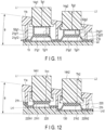
- FIG. 11 is a diagram showing an exemplary cross-section taken along the line A-A shown in FIG. 1 .
- the sixth configuration example is basically similar to the fourth configuration example. More specifically, similar to the fourth configuration example, keys 14 are constituted by, for example, a rubber key 21g, and key tops 14g1 and 14g2 (keytop members).
- the key tops 14g1 and 14g2 are formed of, for example, a resin.
- the rubber key 21g is placed on the upper surface of the substrate 22.
- the rubber key 21g is formed of, for example, an elastic material such as rubber.
- the rubber key 21g includes dome-shaped rubber key tops 21g1 and 21g2 (rubber members) formed at positions corresponding to the respective key tops 14g1 and 14g2 of the multiple keys 14.
- the rubber key tops 21g1 and 21g2 according to the sixth configuration example are formed such that their attachment portions 21g11 and 21g21 enclose respective spacers 52g1 and 52g2.
- the spacers 52g1 and 52g2 and the rubber key 21g are not individually formed for a subsequent bonding, etc., but the spacers 52g1 and 52g2 are enclosed at the time of molding the rubber key 21g.
- the rubber key tops 21g1 and 21g2 are formed to have, assuming that the spacers 52g1 and 52g2 are excluded, substantially the same masses as those of the rubber key tops 21a1 and 21a2 in the first configuration example ( FIG. 5 ).
- the spacers 52g1 and 52g2 are included in the respective configurations of the key tops 14g1 and 14g2.
- the lower ends of the operation parts 14 in the context of the sixth configuration example refer to the lower ends of the spacers 52g1 and 52g2.
- a height Tg11 of the spacer 52g1 and a height Tg12 of the spacer 52g2 are mutually differentiated according to the difference between the heights L1 and L2.
- the spacers 51g1 and 52g2 are formed of a non-elastic material such as a resin, and the configuration of the rubber key 21g (the rubber key tops 21g1 and 21g2) is standardized except for the spacers 52g1 and 52g2.
- the configuration of the rubber key 21g (the rubber key tops 21g1 and 21g2) is standardized except for the spacers 52g1 and 52g2.
- the rubber key tops 21g1 and 21g2 in the multiple keys 14 are formed by enclosing the respective spacers 51g1 and 52g2 differing in height from each other. This allows for the standardization of the rubber key 21g and the key tops 14g1 and 14g2, except for the spacers 52g1 and 52g2, while differentiating the heights from the bottom surface 13 of the housing to the respective operation surfaces of the key tops 14g1 and 14g2. Consequently, variations in operability can be suppressed while reducing the production costs of components.
- FIG. 12 is a diagram showing an exemplary cross-section taken along the line A-A shown in FIG. 1 .
- the seventh configuration example is basically similar to the fifth configuration example. More specifically, keys 14 are constituted by, for example, a rubber key 21h, and key tops 14h1 and 14h2 (keytop members). The key tops 14h1 and 14h2 (the keytop members) are formed of, for example, a resin.
- the key tops 14h1 and 14h2 are formed such that a height Th1 of the key top 14h1 arranged on the first-end side, i.e., the height from its bottom surface to operation surface, and a height Th2 of the key top 14h2 arranged on the second-end side, i.e., the height from its bottom surface to operation surface, are substantially the same. That is, according to the seventh configuration example, not only is the configuration (material / shape (mass)) of the rubber key 21h (rubber key tops 21h1 and 21h2) standardized, but also the key tops 14h1 and 14h2 are standardized.
- a substrate 220 constituted by, for example, a flexible substrate is provided at the inner bottom of the housing of the electronic device 10.
- the substrate 220 supports, inside the housing, the multiple keys 14.
- the inner bottom of the housing is formed to have a stepped profile in the direction from the first-end side to the second-end side in harmonization with the areas where the multiple keys 14 are provided respectively.
- the inner bottom of the housing is formed such that its region (a first region) on the first-end side has a greater height from the housing bottom surface than its region (a second region) on the second-end side.
- the inner bottom of the housing is stepped.
- the heights of the first and second regions from the bottom surface 13 of the housing are mutually differentiated according to the difference between the heights L1 and L2.
- the substrate 220 constituted by a flexible substrate, is laid over the stepped inner bottom of the housing in such a manner as to conform to the shape of the inner bottom.
- a region 220h1 (height Lh1) on the first-end side is higher than a region 220h2 (height Lh2) on the second-end side (Lh1 > Lh2).
- the rubber key 21h is placed on the upper surface of the substrate 220.
- the rubber key 21h is formed of, for example, an elastic material such as rubber.
- the rubber key 21h includes dome-shaped rubber key tops 21h1 and 21h2 (rubber members) formed at positions corresponding to the respective key tops 14h1 and 14h2 of the multiple keys 14.
- the rubber key top 21h1 (the key top 14h1) is arranged in the region 220h1 (the first region) on the first-end side
- the rubber key top 21h2 (the key top 14h2) is arranged in the region 220h2 (the second region) on the second-end side lower than the first region.
- the rubber key tops 21h1 and 21h2 are formed in a similar configuration to that of the rubber key tops 21h1 and 21h2 in the first configuration example ( FIG. 5 ).
- the configuration of the rubber key 21h (the rubber key tops 21h1 and 21h2), as well as the configurations of the key tops 14h1 and 14h2, are standardized so that the variations in operability can be suppressed.
- the inner bottom of the housing is stepped for regions where the keys 14 are arranged so that the heights from the bottom surface 13 of the housing to the respective operation surfaces of the key tops 14h1 and 14h2 can be mutually differentiated.
- the seventh configuration example is also implementable with the configurations of the rubber key (rubber key tops) and the key tops according to the fifth or sixth configuration example.
- the present invention is not limited to the foregoing embodiments.
- various modifications may be adopted without departing from its gist.
- the foregoing embodiments involve various aspects, and appropriate combinations of the features disclosed herein shall permit various inventions to be derived.
- one or more of the features disclosed in the embodiments may be omitted or combined. Provided that such modifications can solve the intended problem and bring the intended effects as discussed above, the modifications should each be deemed an invention.
Landscapes
- Engineering & Computer Science (AREA)
- General Engineering & Computer Science (AREA)
- Theoretical Computer Science (AREA)
- Human Computer Interaction (AREA)
- Physics & Mathematics (AREA)
- General Physics & Mathematics (AREA)
- Computer Hardware Design (AREA)
- Computing Systems (AREA)
- Microelectronics & Electronic Packaging (AREA)
- Push-Button Switches (AREA)
- Input From Keyboards Or The Like (AREA)
- Switches With Compound Operations (AREA)
- Switch Cases, Indication, And Locking (AREA)
- Rotary Switch, Piano Key Switch, And Lever Switch (AREA)
- Liquid Crystal Substances (AREA)
- Glass Compositions (AREA)
- Sheets, Magazines, And Separation Thereof (AREA)
Abstract
Description
- The present invention relates to an electronic device.
- Generally, an electronic device called a calculator is provided with a display and a key input section on the top of its housing. The key input section has multiple keys arranged in a matrix pattern. For example, the key input section has numeric keys, arithmetic keys, function keys, etc., each including multiple keys.
- It is normally the case with a small electronic device such as a calculator that multiple keys of the key input section are operated with one hand while processing results according to inputting of keys are presented on the display and visually recognized.
- The electronic device is desired to be capable of enabling accurate and quick hitting of keys of the key input section, without easily causing fatigue even from use for a long time. Conventionally, a keyboard structure with stepped keys (a step sculpture) for mitigating a physical burden is known. For example, Jpn. UM Appln. KOKAI Publication No.
S60-141035 Japanese Utility Model Application No. S59-29404 - The present invention has been formulated in view of such problems and its objects include providing an electronic device having multiple operation parts which entail reduced variations in operability even if differing in height from each other.
- To solve the problems, an electronic device according to an embodiment includes a plurality of operation parts arranged from a first-end side to a second-end side of a housing and each including a keytop member having an operation surface. The keytop member corresponding to a first operation part, which is one of the operation parts arranged on the first-end side, has a lower-end-to-operation-surface height greater than that of the keytop member corresponding to a second operation part, which is one of the operation parts arranged on the second-end side.
- According to the present invention, it is possible to provide an electronic device having multiple operation parts which entail reduced variations in operability even if differing in height from each other.
-
-
FIG. 1 is a plan view of an electronic device according to an embodiment. -
FIG. 2 is a diagram of the electronic device according to the embodiment, viewed from the lower-side-surface side. -
FIG. 3 is a perspective view of the electronic device according to the embodiment. -
FIG. 4 is a diagram of the electronic device according to the embodiment, viewed from the right-side-surface side. -
FIG. 5 is a diagram showing a first configuration example according to the embodiment, in the cross-section taken along the line A-A shown inFIG. 1 . -
FIG. 6 is a plan view showing an example of a rubber key according to the embodiment. -
FIG. 7 is a diagram showing a second configuration example according to the embodiment, in the cross-section taken along the line A-A shown inFIG. 1 . -
FIG. 8 is a diagram showing a third configuration example according to the embodiment, in the cross-section taken along the line A-A shown inFIG. 1 . -
FIG. 9 is a diagram showing a fourth configuration example according to the embodiment, in the cross-section taken along the line A-A shown inFIG. 1 . -
FIG. 10 is a diagram showing a fifth configuration example according to the embodiment, in the cross-section taken along the line A-A shown inFIG. 1 . -
FIG. 11 is a diagram showing a sixth configuration example according to the embodiment, in the cross-section taken along the line A-A shown inFIG. 1 . -
FIG. 12 is a diagram showing a seventh configuration example according to the embodiment, in the cross-section taken along the line A-A shown inFIG. 1 . - Embodiments of the present invention will be described with reference to the drawings.
-
FIGS. 1, 2 ,3, and 4 are diagrams showing external configurations of anelectronic device 10 according to an embodiment.FIG. 1 is a plan view of theelectronic device 10 according to the embodiment.FIG. 2 is a diagram of theelectronic device 10 according to the embodiment, viewed from the lower-side-surface side.FIG. 3 is a perspective view of theelectronic device 10 according to the embodiment.FIG. 4 is a diagram of theelectronic device 10 according to the embodiment, viewed from the right-side-surface side. - As shown in
FIG. 1 , theelectronic device 10 is provided with akey input section 11 and adisplay section 12 on the top surface of its housing. Thekey input section 11 hasmultiple keys 14, one ormore selector switches 15, and so on. - The
multiple keys 14 include, for example, numeric keys, arithmetic keys, function keys, etc. The numeric keys include, for example, multiple keys corresponding to [00] and [0] to [9], respectively. The arithmetic keys include, for example, keys for use in normal calculations according to four arithmetic operations, such as keys corresponding to [+] (addition), [-] (subtraction), [×] (multiplication), [÷] (division), and [=] (execution), respectively. The function keys include, for example, an all-clear key (an [AC] key), a clear key (a [C] key), multiple memory keys ([MRC], [M-], and [M+] keys), a root key (a [V] key), and a [%] key. - The selector switch or
switches 15 include, for example, a round selector and a decimal point selector. - As shown in
FIG. 1 , the housing top surface of theelectronic device 10 is formed in a substantially rectangular outer shape. The housing top surface includes thedisplay section 12 on an upper side (the upper-edge side of the housing top surface) and thekey input section 11 on a lower side (the lower-edge side of the housing top surface). - In the
display section 12, adisplay 16 is disposed on afirst housing surface 12a which is a first region (the upper side) of the housing top surface. Thedisplay 16 has, for example, a horizontally long rectangular display surface and extends from a first-end side (the left-edge side inFIG. 1 ) of the housing to a second-end side (the right-edge side inFIG. 1 ) opposite the first-end side. - In the
key input section 11, multiple keys 14 (operation parts) are arranged from the first-end side to the second-end side of the housing and on asecond housing surface 11a which is a second region (the lower side) of the housing top surface. Themultiple keys 14 each have anoperation surface 14t on their respective key tops. Themultiple keys 14, in one example, are arranged at predetermined intervals (key pitches) in each of the row and column directions, with the row direction assumed to be a direction parallel to the upper edge/the lower edge of the housing top surface and the column direction assumed to be a direction parallel to the left edge/the right edge of the housing top surface. - In the
electronic device 10 according to the embodiment, thesecond housing surface 11a of thekey input section 11 is inclined in a direction from the first-end side to the second-end side, i.e., in the row direction of the arrangement of themultiple keys 14, at a first inclination angle (angle θ) with respect to the placement surface (the bottom surface of the housing). Also, thefirst housing surface 12a for thedisplay section 12 is substantially in parallel (or substantially horizontal) to the placement surface (the bottom surface of the housing), or is inclined in the direction from the first-end side to the second-end side, i.e., in the row direction of the arrangement of themultiple keys 14, at a second inclination angle different from the first inclination angle (angle θ) with respect to the bottom surface of the housing. - As shown in
FIGS. 2 and4 , thesecond housing surface 11a of theelectronic device 10 is formed to be inclined in the row direction, in which thekeys 14 are arranged, at the angle θ with respect to thebottom surface 13 of the housing. As an example, it is preferred that the angle θ be in a range of 1° to 9°. It is further preferred that the angle θ be in a range of, for example, 1° to 3° (this will be described in more detail later). -
FIGS. 1 to 4 illustrate a configuration of theelectronic device 10 which is an example where thesecond housing surface 11a of thekey input section 11 has a rightward inclination (the left-edge side is higher than the right-edge side) as depicted inFIGS. 2 and4 . In other words, at least a portion of theoperation surface 14t of the key 14 (a first operation part) on the first-end side (the left-edge side) is formed to have a greater height from the placement surface (the bottom surface of the housing) than that of at least a portion of theoperation surface 14t of the key 14 (a second operation part) on the second-end side (the right-edge side). For example, the central portion (a first central portion) of theoperation surface 14t of thekey 14 arranged on the first-end side has a greater height from the placement surface (the bottom surface of the housing) than that of the central portion (a second central portion) of theoperation surface 14t of thekey 14 arranged on the second-end side. - This realizes good operability with the
multiple keys 14 and prevents the user from being easily fatigued in the instances where the user operates theelectronic device 10 with the right hand (the user is a right-handed user). - Note that, assuming that the user operates the
electronic device 10 with the left hand (the user is a left-handed user), it is also possible to adopt a configuration in which thesecond housing surface 11a of thekey input section 11 has a leftward inclination. In other words, at least a portion of theoperation surface 14t of the key 14 on the second-end side (the right-edge side) is formed to have a greater height from the placement surface (the bottom surface of the housing) than that of at least a portion of theoperation surface 14t of the key 14 on the first-end side (the left-edge side). - On the other hand, the display surface of the
display section 12 is formed such that its portion on the first-end side has a height from the placement surface (the bottom surface of the housing) not greater than that of its portion on the second-end side. In the example shown inFIGS. 2 and4 , the first-end portion (the left-edge portion) and the second-end portion (the right-edge portion) of thedisplay section 12 are aligned at the same height, and the upper-edge side of the housing top surface is raised from the boundary between thekey input section 11 and thedisplay section 12, so that the inclination in the column direction (the front-and-back direction) of the arrangement of themultiple keys 14 is formed. - As shown in
FIG. 4 , the housing of theelectronic device 10 is bent at the boundary between thekey input section 11 and thedisplay section 12 so that the upper-edge side of the housing top surface is positioned higher. Accordingly, thefirst housing surface 12a of thedisplay section 12 is inclined in the column direction in which themultiple keys 14 are arranged, thereby enhancing viewability of the display surface of thedisplay 16. - Next, some examples of the configuration of the multiple keys 14 (operation parts) according to the embodiment will be described (as first to seventh configuration examples) with reference to
FIGS. 5 to 12 . -
FIG. 5 is a diagram showing an exemplary cross-section taken along the line A-A shown inFIG. 1 .FIG. 5 only shows, among themultiple keys 14 arranged along the line A-A, two consecutively arrangedkeys 14. Illustrations inFIGS. 7 to 12 are given in a similar manner. - Note that illustrations in
FIGS. 5 and7 to 12 discussed below involve deformations for facilitating the understanding of the configuration of themultiple keys 14 provided for theelectronic device 10, and as such, they may not perfectly conform to the configurations shown inFIGS. 1 to 4 . - According to the first configuration example as shown in
FIG. 5 , asubstrate 22 is provided at the bottom portion inside the housing of theelectronic device 10, in a state parallel to thebottom surface 13 of the housing. Thesubstrate 22 supports, inside the housing, themultiple keys 14. - The
keys 14 are constituted by, for example, a rubber key 21a, and key tops 14a1 and 14a2 (keytop members). The key tops 14a1 and 14a2 (the keytop members) are formed of, for example, a resin. The rubber key 21a is placed on the upper surface of thesubstrate 22. The rubber key 21a is formed of, for example, an elastic material such as rubber. The rubber key 21a includes dome-shaped rubber key tops 21a1 and 21a2 (rubber members) formed at positions corresponding to the respective key tops 14a1 and 14a2 of themultiple keys 14. - The rubber key tops 21a1 and 21a2 are constituted by respective attachment portions 21a11 and 21a22 to which the lower ends of the key tops 14a1 and 14a2 are attached, and respective support portions 21a12 and 21a22 which support the attachment portions 21a11 and 21a21 in a state separated from the substrate 24.
- The attachment portions 21a11 and 21a22 are supported by the support portions 21a12 and 21a22 so that they are normally separated from the substrate 24 but are pressed downward until they contact the substrate 24 at the time of a depressing action, in order to provide operability in response to a depressing action on the key tops 14a1 and 14a2 attached on the respective attachment portions 21a11 and 21a21.
- The rubber key tops 21a1 and 21a2 are standardized for providing the same operability (feel of a click) at depressing actions on the key tops 14a1 and 14a2. In other words, the rubber key tops 21a1 and 21a2 are formed from the same material (constituent), the same shape, and the same size to substantially equal each other in mass, etc.
- As used herein, a "feel of a click" refers to a sense taken by the user upon recognizing a repulsion (an elastic force) produced by the rubber key top 21a1 or 21a2 squashed by the user's depressing action on the key top 14a1 or 14a2.
-
FIG. 6 is a plan view showing an example of the rubber key 21a according to the embodiment. - As shown in
FIG. 6 , the rubber key 21a has multiple rubber key tops at positions coinciding with themultiple keys 14 arranged on thesecond housing surface 11a of thekey input section 11 shown inFIG. 1 . InFIG. 6 , the rubber key tops 21a1 and 21a2, to which the respective key tops 14a1 and 14a2 of the two keys arranged along the line A-A are attached, are included. - To the rubber key tops 21a1 and 21a2, the respectively corresponding key tops 14a1 and 14a2 are attached via the attachment portions 21a11 and 21a22 so that their key stroke directions (sliding directions) are made perpendicular to the
bottom surface 13 of the housing (the placement surface of the housing). - The rubber key tops 21a1 and 21a2 (the attachment portions 21a11 and 21a22) are each provided with a conductive member at their bottoms so that the rubber key tops 21a1 and 21a2 pressed downward by the depressing action on the key tops 14a1 and 14a2 will cause the conductive members to contact electrodes arranged on the
substrate 22 for the detection of key depression events. - The key tops 14a1 and 14a2 are formed to have mutually different heights, each being a height from the bottom surface (the lower end) to the operation surface, according to their arrangement positions in the area from the first-end side (the key top 14a1 side) to the second-end side (the key top 14a2 side). In
FIG. 5 , thesecond housing surface 11a of thekey input section 11 is inclined to the right, and as such, a height Ta1 of the key top 14a1 arranged on the first-end side, i.e., the height from its bottom surface to operation surface 14ta1, is greater than a height Ta2 of the key top 14a2 arranged on the second-end side, i.e., the height from its bottom surface to operation surface 14ta2. - Accordingly, the operation surfaces 14ta1 and 14ta2 are set at the same height from the inclined
second housing surface 11a so that the heights of the operation surfaces 14ta1 and 14ta2 from thebottom surface 13 of the housing (the placement surface of the housing) show a stepped profile according to the inclination angle θ of thesecond housing surface 11a. - While
FIG. 5 shows only the two key tops 14a1 and 14a2, the multiple key tops arranged from the first-end side to the second-end side are formed in a similar configuration to that of the key tops 14a1 and 14a2 so that the operation surfaces of the multiple key tops are stepped according to the inclination angle θ. Basically, a constant height difference is set between operation surfaces of the multiple consecutive key tops. - The
second housing surface 11a (the housing top surface) has openings corresponding to themultiple keys 14, respectively. The openings are each formed in such a manner that the opening wall surface is substantially perpendicular (vertical) to thebottom surface 13 of the housing (the placement surface of the housing). The key tops 14a1 and 14a2 slidably pass through the corresponding openings, and their respective operation surfaces 14ta1 and 14ta2 are supported at levels higher than thesecond housing surface 11a in the normal state. As such, the side surfaces of the key tops 14a1 and 14a2 each extend substantially in parallel to the opening wall surface of the corresponding opening and face this corresponding opening wall surface with a slight clearance therebetween. - Also, ribs 31a1 and 31a2 (slide assisting members) are formed to extend in the sliding direction of the key tops 14a1 and 14a2, i.e., the direction perpendicular to the
bottom surface 13 of the housing (the placement surface of the housing), from the respective openings of thesecond housing surface 11a. The side surfaces of the ribs 31a1 and 31a2 facing the respective key tops 14a1 and 14a2 each extend substantially in parallel to the corresponding key top 14a1 or 14a2 and face the corresponding key top 14a1 or 14a2 with a slight clearance therebetween. The ribs 31a1 and 31a2, extending in the sliding direction of the key tops 14a1 and 14a2 from the respective openings, can prevent the key tops 14a1 and 14a2 from wobbling in such a manner as to keep them within the slight clearance during their sliding movement. - The
second housing surface 11a (the housing top surface) is inclined at the angle θ, and the attachment portions 21a11 and 21a22 have the same height (at the same level) from thebottom surface 13 of the housing. As such, the ribs 31a1 and 31a2 are each formed to have lengths from the back of thesecond housing surface 11a (the inner surface of the housing) to the position abutting the flanged bottom of the key top 14a1 or 14a2 (or to the contact position in the non-operating state) such that the length on the first-end side (the key top 14a1 side) is greater than the length on the second-end side (the key top 14a2 side). In other words, the ribs 31a1 and 31a2 have lengths varying in the sliding direction of the key tops 14a1 and 14a2 (the direction perpendicular to thebottom surface 13 of the housing) according to the heights of the key tops 14a1 and 14a2. - Therefore, with the respective ribs 31a1 and 31a2, the key tops 14a1 and 14a2 are prevented from wobbling.
- As shown in
FIG. 5 , the operation surfaces 14ta1 and 14ta2 (upper surfaces) of the key tops 14a1 and 14a2 are each formed to be in parallel to thebottom surface 13. In other words, in instances where theelectronic device 10 is placed in a horizontal site, the operation surfaces 14ta1 and 14ta2 of the key tops 14a1 and 14a2 are horizontal. Also, heights L1 and L2 of the respective key tops 14a1 and 14a2 decrease in order from the key top 14a1 on the first-end side and the key top 14a2 on the second-end side. - The key tops 14a1 and 14a2 are formed in an analogous shape with a comparable stroke length defined by the movable ranges of the rubber key tops 21a1 and 21a2, and therefore, the heights L1 and L2 from the
bottom surface 13 show a stepped profile according to the inclination angle θ of thesecond housing surface 11a as shown inFIGS. 2 and3 . - In the electronic device 1 according to the embodiment as shown in
FIGS. 2 and4 , thesecond housing surface 11a of thekey input section 11 is inclined in the row direction of thekeys 14 at the angle θ with respect to thebottom surface 13, and theoperation surface 14t of the key 14 disposed on the first-end side is higher than theoperation surface 14t of the key 14 disposed on the second-end side. This realizes good operability with thekeys 14 and prevents the user from being easily fatigued. - Also, the
rubber key 21a (the rubber key tops 21a1 and 21a2) has a standardized configuration (material / shape (mass)) for themultiple keys 14, while the key tops 14a1 and 14a2 have mutually different heights from their respective bottom surfaces to operation surfaces 14ta1 and 14ta2. This realizes reduced variations in operability while having different heights of the operation surfaces 14ta1 and 14ta2 of the key tops 14a1 and 14a2 from thebottom surface 13 of the housing. -
FIG. 7 is a diagram showing an exemplary cross-section taken along the line A-A shown inFIG. 1 . - The second configuration example is basically similar to the first configuration example. More specifically,
keys 14 are constituted by, for example, a rubber key 21b and key tops 14b1 and 14b2 (keytop members). The key tops 14b1 and 14b2 (the keytop members) are formed of, for example, a resin. The rubber key 21b is placed on the upper surface of thesubstrate 22. Similar to the rubber key 21a described above, the rubber key 21b is formed of, for example, an elastic material such as rubber. The rubber key 21b includes dome-shaped rubber key tops 21b1 and 21b2 (rubber members) formed at positions corresponding to the respective key tops 14b1 and 14b2 of themultiple keys 14. - The rubber key tops 21b1 and 21b2 are formed in a similar configuration to that of the rubber key tops 21a1 and 21a2 in the first configuration example (
FIG. 5 ). Also, the ribs 31b1 and 31b2 are formed in a similar configuration to that of the ribs 31a1 and 31a2 in the first configuration example (FIG. 5 ). - Similar to the first configuration example, the key tops 14b1 and 14b2 are formed such that a height Tb1 of the key top 14b1 arranged on the first-end side, i.e., the height from its bottom surface to operation surface 14tb1, is greater than a height Tb2 of the key top 14b2 arranged on the second-end side, i.e., the height from its bottom surface to operation surface 14tb2.
- For the key tops 14b1 and 14b2 in the second configuration example, a hollowing-out amount from components is differentiated for each key. The key tops 14b1 and 14b2, as in the first configuration example, are formed to have mutually different heights, each being a height from the bottom surface to the operation surface, according to their arrangement positions in the area from the first-end side (the key top 14a1 side) to the second-end side (the key top 14a2 side), and the key top 14b1 on the first-end side has a greater height than the key top 14b2. As such, assuming that the components are not hollow, the key top 14b1 has a greater mass.
- According to the second configuration example, a greater hollowing-out amount is adopted for components having a greater height from the bottom surface to the operation surface so that the multiple key tops arranged in the area from the first-end side to the second-end side have substantially the same mass. In the example shown in
FIG. 7 , as one exemplary form, the key top 14b1 is hollowed out with support members 41b1 left inside, and the key top 14b2 is hollowed out with more support members 41b2 left as compared to the key top 14b1. - Thus, at the same time as realizing unified operability with the
multiple keys 14 by standardizing the configuration (material / shape (mass)) of the rubber key 21b for themultiple keys 14, the masses of the key tops themselves, i.e., the key tops 14b1 and 14b2, can be made substantially equal to each other by adjusting the hollowed-out amounts from the key tops 14b1 and 14b2. Accordingly, a burden on therubber key 21b (the rubber key tops 21b1 and 21b2) is reduced and an improved durability can also be realized. -
FIG. 8 is a diagram showing an exemplary cross-section taken along the line A-A shown inFIG. 1 . - The third configuration example is basically similar to the first configuration example. More specifically, similar to the first configuration example,
keys 14 are constituted by, for example, a rubber key 21d, and key tops 14d1 and 14d2 (keytop members). The key tops 14d1 and 14d2 (the keytop members) are formed of, for example, a resin. The rubber key 21d (a rubber member) is placed on the upper surface of thesubstrate 22. The rubber key 21d is formed of, for example, an elastic material such as rubber. The rubber key 21d includes dome-shaped rubber key tops 21d1 and 21d2 (rubber members) formed at positions corresponding to the respective key tops 14d1 and 14d2 of themultiple keys 14. - The rubber key tops 21d1 and 21d2 are formed in a similar configuration to that of the rubber key tops 21a1 and 21a2 in the first configuration example (
FIG. 5 ). - Similar to the first configuration example, the key tops 14d1 and 14d2 are formed such that a height Td1 of the key top 14d1 arranged on the first-end side, i.e., the height from its bottom surface to operation surface 14td1, is greater than a height Td2 of the key top 14d2 arranged on the second-end side, i.e., the height from its bottom surface to operation surface 14td2.
- Note that the
second housing surface 11b in the third configuration example does not have ribs, unlike in the first configuration example. - In the third configuration example, support members 34d1 and 34d2 extending in the sliding direction of the key tops 14d1 and 14d2 are formed at positions inside the respective key tops 14d1 and 14d2 of the
multiple keys 14 and lateral to the respective rubber key tops 21d1 and 21d2 (the rubber members). The support members 34d1 and 34d2 are, for example, formed integrally with the housing and perpendicularly to thebottom surface 13 of the housing from, for example, above the rubber key 21d. - The key tops 14d1 and 14s2 are provided with, at their inside, respective spaces for forming support member receivers 43d1 and 43d2 for slidably retaining the support members 34d1 and 34d2. The support member receivers 43d1 and 43d2, as one exemplary form, are each constituted by a space between the outer peripheral portion and the axial portion of the corresponding key top 14d1 or 14d2 and support the corresponding support member 34d1 or 34d2 within the space. The axial portions of the key tops 14d1 and 14d2 are each formed in, for example, a cylindrical shape, and the corresponding rubber key top 21d1 or 21d2 (the rubber member) is attached to the lower end (the bottom surface) of such a cylindrical portion.
- The key tops 14d1 and 14d2 have the respective flanges 42d1 and 42d2 at the lower ends of their outer peripheral portions. The outer peripheral portions of the key tops 14d1 and 14d2 are each formed to have a length from the operation surface 14td1 or 14td2 such that the flanges 42d1 and 42d2 are each placed at the position abutting the back of the
second housing surface 11a (the inner surface of the housing) (or at the contact position in the non-operating state). - The support member receivers 43d1 and 43d2 (spaces) are each formed to have, for example, the maximum length (such as a length up to the vicinity of the operation surface 14td1) according to the heights Td1 and Td2 of the key tops 14d1 and 14d2. The support members 34d1 and 34d2 are also each formed to have, for example, the maximum length according to the heights Td1 and Td2 of the key tops 14d1 and 14d2, within the range where the key tops 14d1 and 14d2 can slide by means of the support member receivers 43d1 and 43d2 (spaces). In other words, in the configuration shown in
FIG. 8 , the support member receiver 43d1 is longer than the support member receiver 43d2, and the support member 34d1 is longer than the support member 34d2. - This enables the support member receivers 43d1 and 43d2 and the support members 34d1 and 34d2 to provide the longest-possible support for the key tops 14d1 and 14d2 at their sliding movement (at the stroke caused by a depressing action). Therefore, the wobbling of the key tops 14d1 and 14d2 can be minimized.
-
FIG. 9 is a diagram showing an exemplary cross-section taken along the line A-A shown inFIG. 1 . - The fourth configuration example is basically similar to the first configuration example. More specifically, similar to the first configuration example,
keys 14 are constituted by, for example, a rubber key 21e, and key tops 14e1 and 14e2 (keytop members). The key tops 14e1 and 14e2 (the keytop members) are formed of, for example, a resin. The rubber key 21e is placed on the upper surface of thesubstrate 22. The rubber key 21e is formed of, for example, an elastic material such as rubber. The rubber key 21e includes dome-shaped rubber key tops 21e1 and 21e2 (rubber members) formed at positions corresponding to the respective key tops 14e1 and 14e2 of themultiple keys 14. - The rubber key tops 21e1 and 21e2 are formed in a similar configuration to that of the rubber key tops 21a1 and 21a2 in the first configuration example (
FIG. 5 ). - Similar to the first configuration example, the key tops 14e1 and 14e2 are formed such that a height Te1 of the key top 14d1 arranged on the first-end side, i.e., the height from its bottom surface to operation surface 14te1, is greater than a height Te2 of the key top 14e2 arranged on the second-end side, i.e., the height from its bottom surface to operation surface 14te2.
- The
second housing surface 11b in the fourth configuration example does not have ribs, unlike in the first configuration example (and similar to the third configuration example). In the fourth configuration example, the key tops 14e1 and 14e2 have, at their respective bottom portions, flanges 45e1 and 45e2 differing in height (thickness) from each other. - More specifically, the
second housing surface 11b (the housing top surface) is inclined at the angle θ, and accordingly, the key tops 14e1 and 14e2 have mutually different heights from their bottom surfaces to the back of thesecond housing surface 11b (the inner surface of the housing). The flanges 45e1 and 45e2 are each formed to have a thickness that is in accordance with the height of the corresponding key top 14e1 or 14e2 from the bottom surface to the back of thesecond housing surface 11b (the inner surface of the housing), such that the upper surfaces of the flanges 45e1 and 45e2 are each placed at the position facing the back of thesecond housing surface 11b (the inner surface of the housing), that is, at the position abutting the same or at the contact position in the non-operating state. As such, the flange 45e1 formed at the key top 14e1 has a height Te11 which is greater than a height Te21 of the flange 45e2 formed at the key top 14e2 (the former is thicker than the latter). - Therefore, even without the ribs formed at the openings of the
second housing surface 11a (the housing top surface) as in the first configuration example, the key tops 14e1 and 14e2 can be stably held via thesecond housing surface 11b so that wobbling can be suppressed. - The first to fourth configuration examples have assumed standardizing the configuration (material / shape (mass)) of each rubber key (the rubber key tops) for the
multiple keys 14 and mutually differentiating the heights of the key tops from their bottom surfaces to operation surfaces so as to have different heights from thebottom surface 13 of the housing to the respective operation surfaces of the key tops. According to the fifth to seventh configuration examples, spacers are provided for the sake of different heights from thebottom surface 13 of the housing to the respective operation surfaces of the key tops. -
FIG. 10 is a diagram showing an exemplary cross-section taken along the line A-A shown inFIG. 1 . - The fifth configuration example is basically similar to the fourth configuration example. More specifically, similar to the fourth configuration example,
keys 14 are constituted by, for example, a rubber key 21f, and key tops 14f1 and 14f2 (keytop members). The key tops 14f1 and 14f2 (the keytop members) are formed of, for example, a resin. Therubber key 21f is placed on the upper surface of thesubstrate 22. Therubber key 21f is formed of, for example, an elastic material such as rubber. Therubber key 21f includes dome-shaped rubber key tops 21f1 and 21f2 (rubber members) formed at positions corresponding to the respective key tops 14f1 and 14f2 of themultiple keys 14. - The rubber key tops 21f1 and 21f2 are formed in a similar configuration to that of the rubber key tops 21a1 and 21a2 in the first configuration example (
FIG. 5 ). - In the fifth configuration example, in order for the heights L1 and L2 from the
bottom surface 13 of the housing to the operation surfaces of the key tops 14f1 and 14f2 to have a stepped profile as in the first configuration example, the key tops 14f1 and 14f2 are formed by including respective spacers 51f1 and 52f2 differing in height from each other. While heights Tf1 and Tf2 of the key tops 14f1 and 14f2 excluding the spacers 51f1 and 52f2 are the same, heights Tf11 and Tf21 of the spacers 51f1 and 52f2 are mutually differentiated according to the difference between the heights L1 and L2. - As such, the height of the key top 14f1 from its lower end to operation surface 14f1 equals Tf1 + Tf11, and the height of the key top 14f2 from its lower end to operation surface 14f2 equals Tf2 + Tf12. Thus, the key top 14f21 arranged on the first-end side has a greater height than the key top 14f2 arranged on the second-end side. In other words, the lower ends of the keys 14 (operation parts) in the context of the fifth configuration example refer to the lower ends of the spacers 51f1 and 52f2.
- The spacers 51f1 and 52f2, in one example, are formed of a non-elastic material such as a resin. Thus, for the action of depressing the key tops 14f1 and 14f2 to cause the bottom surfaces of the rubber key tops 21f1 and 21f2 to contact the
substrate 22, no difference in operability is produced between the key tops 14f1 and 14f2. - As described above, the key tops 14f1 and 14f2 in the
multiple keys 14 are formed by including the respective spacers 51f1 and 52f2 differing in height from each other. This allows for the standardization of the rubber key 21f and the key tops 14f1 and 14f2 while differentiating the heights from thebottom surface 13 of the housing to the respective operation surfaces of the key tops 14f1 and 14f2. Consequently, variations in operability can be suppressed while reducing the production costs of components. - Note that the fifth configuration example is applicable to the foregoing first to fourth configuration examples. That is, the key tops may be formed by including respective spacers differing in height as in the fifth configuration example, so as to provide mutually different heights of the operation surfaces.
-
FIG. 11 is a diagram showing an exemplary cross-section taken along the line A-A shown inFIG. 1 . - The sixth configuration example is basically similar to the fourth configuration example. More specifically, similar to the fourth configuration example,
keys 14 are constituted by, for example, arubber key 21g, and key tops 14g1 and 14g2 (keytop members). The key tops 14g1 and 14g2 (the keytop members) are formed of, for example, a resin. Therubber key 21g is placed on the upper surface of thesubstrate 22. Therubber key 21g is formed of, for example, an elastic material such as rubber. Therubber key 21g includes dome-shaped rubber key tops 21g1 and 21g2 (rubber members) formed at positions corresponding to the respective key tops 14g1 and 14g2 of themultiple keys 14. - The rubber key tops 21g1 and 21g2 according to the sixth configuration example are formed such that their attachment portions 21g11 and 21g21 enclose respective spacers 52g1 and 52g2. The spacers 52g1 and 52g2 and the
rubber key 21g are not individually formed for a subsequent bonding, etc., but the spacers 52g1 and 52g2 are enclosed at the time of molding therubber key 21g. - The rubber key tops 21g1 and 21g2 are formed to have, assuming that the spacers 52g1 and 52g2 are excluded, substantially the same masses as those of the rubber key tops 21a1 and 21a2 in the first configuration example (
FIG. 5 ). - It will be assumed that the spacers 52g1 and 52g2 are included in the respective configurations of the key tops 14g1 and 14g2. In other words, the lower ends of the
operation parts 14 in the context of the sixth configuration example refer to the lower ends of the spacers 52g1 and 52g2. - In the sixth configuration example, in order for the heights L1 and L2 from the
bottom surface 13 of the housing to the operation surfaces of the key tops 14g1 and 14g2 to have a stepped profile as in the first configuration example, a height Tg11 of the spacer 52g1 and a height Tg12 of the spacer 52g2 are mutually differentiated according to the difference between the heights L1 and L2. - The spacers 51g1 and 52g2, in one example, are formed of a non-elastic material such as a resin, and the configuration of the
rubber key 21g (the rubber key tops 21g1 and 21g2) is standardized except for the spacers 52g1 and 52g2. Thus, for the action of depressing the key tops 14g1 and 14g2 to cause the bottom surfaces of the rubber key tops 21g1 and 21g2 to contact thesubstrate 22, no difference in operability is produced between the key tops 14g1 and 14g2. - As described above, the rubber key tops 21g1 and 21g2 in the
multiple keys 14 are formed by enclosing the respective spacers 51g1 and 52g2 differing in height from each other. This allows for the standardization of therubber key 21g and the key tops 14g1 and 14g2, except for the spacers 52g1 and 52g2, while differentiating the heights from thebottom surface 13 of the housing to the respective operation surfaces of the key tops 14g1 and 14g2. Consequently, variations in operability can be suppressed while reducing the production costs of components. -
FIG. 12 is a diagram showing an exemplary cross-section taken along the line A-A shown inFIG. 1 . - The seventh configuration example is basically similar to the fifth configuration example. More specifically,
keys 14 are constituted by, for example, a rubber key 21h, and key tops 14h1 and 14h2 (keytop members). The key tops 14h1 and 14h2 (the keytop members) are formed of, for example, a resin. - In the seventh configuration example, the key tops 14h1 and 14h2 are formed such that a height Th1 of the key top 14h1 arranged on the first-end side, i.e., the height from its bottom surface to operation surface, and a height Th2 of the key top 14h2 arranged on the second-end side, i.e., the height from its bottom surface to operation surface, are substantially the same. That is, according to the seventh configuration example, not only is the configuration (material / shape (mass)) of the rubber key 21h (rubber key tops 21h1 and 21h2) standardized, but also the key tops 14h1 and 14h2 are standardized.
- In the seventh configuration example, a
substrate 220 constituted by, for example, a flexible substrate is provided at the inner bottom of the housing of theelectronic device 10. Thesubstrate 220 supports, inside the housing, themultiple keys 14. - The inner bottom of the housing is formed to have a stepped profile in the direction from the first-end side to the second-end side in harmonization with the areas where the
multiple keys 14 are provided respectively. In other words, the inner bottom of the housing is formed such that its region (a first region) on the first-end side has a greater height from the housing bottom surface than its region (a second region) on the second-end side. - In the seventh configuration example, in order for the heights L1 and L2 from the
bottom surface 13 of the housing to the operation surfaces of the key tops 14h1 and 14h2 to have a stepped profile as in the first configuration example, the inner bottom of the housing is stepped. The heights of the first and second regions from thebottom surface 13 of the housing are mutually differentiated according to the difference between the heights L1 and L2. - The
substrate 220, constituted by a flexible substrate, is laid over the stepped inner bottom of the housing in such a manner as to conform to the shape of the inner bottom. As such, in terms of the height from the housing bottom surface to thesubstrate 220, a region 220h1 (height Lh1) on the first-end side is higher than a region 220h2 (height Lh2) on the second-end side (Lh1 > Lh2). - The
rubber key 21h is placed on the upper surface of thesubstrate 220. Therubber key 21h is formed of, for example, an elastic material such as rubber. Therubber key 21h includes dome-shaped rubber key tops 21h1 and 21h2 (rubber members) formed at positions corresponding to the respective key tops 14h1 and 14h2 of themultiple keys 14. In other words, the rubber key top 21h1 (the key top 14h1) is arranged in the region 220h1 (the first region) on the first-end side, and the rubber key top 21h2 (the key top 14h2) is arranged in the region 220h2 (the second region) on the second-end side lower than the first region. - The rubber key tops 21h1 and 21h2 are formed in a similar configuration to that of the rubber key tops 21h1 and 21h2 in the first configuration example (
FIG. 5 ). - As described above, the configuration of the
rubber key 21h (the rubber key tops 21h1 and 21h2), as well as the configurations of the key tops 14h1 and 14h2, are standardized so that the variations in operability can be suppressed. Together, the inner bottom of the housing is stepped for regions where thekeys 14 are arranged so that the heights from thebottom surface 13 of the housing to the respective operation surfaces of the key tops 14h1 and 14h2 can be mutually differentiated. - Note that the seventh configuration example is also implementable with the configurations of the rubber key (rubber key tops) and the key tops according to the fifth or sixth configuration example.
- The present invention is not limited to the foregoing embodiments. For practical implementation, various modifications may be adopted without departing from its gist. Moreover, the foregoing embodiments involve various aspects, and appropriate combinations of the features disclosed herein shall permit various inventions to be derived. For example, one or more of the features disclosed in the embodiments may be omitted or combined. Provided that such modifications can solve the intended problem and bring the intended effects as discussed above, the modifications should each be deemed an invention.
- According to the present invention, it is possible to provide an electronic device having multiple operation parts which entail reduced variations in operability even if they differ in height from each other.
-
- 10
- Electronic device
- 11
- key input section
- 12
- Display section
- 13
- Bottom surface
- 14
- Key
- 16
- Display
Claims (10)
- An electronic device comprising:a plurality of operation parts arranged from a first-end side to a second-end side of a housing and each including a keytop member having an operation surface,characterized in thatthe keytop member corresponding to a first operation part, which is one of the operation parts arranged on the first-end side, has a lower-end-to-operation-surface height greater than that of the keytop member corresponding to a second operation part, which is one of the operation parts arranged on the second-end side.
- The electronic device according to claim 1, characterized in thatthe operation parts each further include a rubber member supporting the corresponding keytop member, andthe rubber members of the first operation part and the second operation part are standardized in shape, size, and material.
- The electronic device according to claim 1 or 2, characterized in thata top surface of the housing is inclined in a direction from the first-end side to the second-end side at a predetermined inclination angle with respect to a placement surface,the top surface of the housing includes openings through which the keytop members slidably pass in a direction perpendicular to the placement surface,slide assisting members are formed at the openings of the top surface of the housing and each extend in a sliding direction of the corresponding keytop member, the slide assisting members each being configured to prevent the corresponding keytop member from sliding in a direction different from the sliding direction, andthe slide assisting members have lengths in the sliding direction which vary according to the heights of the keytop members corresponding to the respective first and second operation parts.
- The electronic device according to any one of claims 1 to 3, characterized in that a hollowing-out amount from the keytop member corresponding to the first operation part is greater than that from the keytop member corresponding to the second operation part.
- The electronic device according to claim 2, characterized in thatin the operation parts, support members each extending in a sliding direction of the corresponding keytop member are formed at a position inside the corresponding keytop member and lateral to the corresponding rubber member, andthe support members have lengths differing from each other according to the heights of the keytop members corresponding to the respective first and second operation parts.
- The electronic device according to any one of claims 1, 2, and 4, characterized in thata top surface of the housing is inclined in a direction from the first-end side to the second-end side at a predetermined inclination angle with respect to a placement surface,the top surface of the housing includes openings through which the keytop members slidably pass in a direction perpendicular to the placement surface,the keytop members corresponding to the respective first and second operation parts each include a portion facing an inner surface of the housing that corresponds to the top surface of the housing, andthe keytop members corresponding to the first and second operation parts have mutually different lengths from respective lower ends to positions facing the inner surface of the housing that corresponds to the top surface of the housing.
- The electronic device according to any one of claims 1 to 6, characterized in thatthe keytop members each include a spacer, andthe spacer in the first operation part is thicker than the spacer in the second operation part so that the lower-end-to-operation-surface height of the keytop member corresponding to the first operation part is greater than that of the keytop member corresponding to the second operation part.
- An electronic device comprising:a plurality of operation parts arranged from a first-end side to a second-end side of a housing and each including a keytop member having an operation surface; anda substrate provided with the operation parts,characterized in thatthe keytop member corresponding to a first operation part, which is one of the operation parts arranged on the first-end side, has a lower-end-to-operation-surface height substantially equal to that of the keytop member corresponding to a second operation part, which is one of the operation parts arranged on the second-end side,the first operation part is arranged in a first region of the substrate,the second operation part is arranged in a second region of the substrate, andthe first region has a greater height from a bottom surface of the housing to the substrate than that of the second region.
- The electronic device according to claim 8, characterized in thatthe operation parts each further include a rubber member supporting the corresponding keytop member, andthe rubber members of the first operation part and the second operation part are standardized in shape, size, and material.
- The electronic device according to claim 8 or 9, characterized in that the substrate is constituted by a flexible substrate which is bendable.
Applications Claiming Priority (2)
| Application Number | Priority Date | Filing Date | Title |
|---|---|---|---|
| JP2022041402A JP7315055B1 (en) | 2022-03-16 | 2022-03-16 | Electronics |
| PCT/JP2023/004588 WO2023176230A1 (en) | 2022-03-16 | 2023-02-10 | Electronic device |
Publications (2)
| Publication Number | Publication Date |
|---|---|
| EP4495971A1 true EP4495971A1 (en) | 2025-01-22 |
| EP4495971A4 EP4495971A4 (en) | 2025-07-09 |
Family
ID=87427974
Family Applications (1)
| Application Number | Title | Priority Date | Filing Date |
|---|---|---|---|
| EP23770191.7A Pending EP4495971A4 (en) | 2022-03-16 | 2023-02-10 | ELECTRONIC DEVICE |
Country Status (7)
| Country | Link |
|---|---|
| US (1) | US20240188230A1 (en) |
| EP (1) | EP4495971A4 (en) |
| JP (3) | JP7315055B1 (en) |
| KR (1) | KR102871308B1 (en) |
| CN (1) | CN117529790A (en) |
| TW (2) | TWI909385B (en) |
| WO (1) | WO2023176230A1 (en) |
Families Citing this family (3)
| Publication number | Priority date | Publication date | Assignee | Title |
|---|---|---|---|---|
| JP7315055B1 (en) * | 2022-03-16 | 2023-07-26 | カシオ計算機株式会社 | Electronics |
| JP2025050498A (en) * | 2023-09-25 | 2025-04-04 | カシオ計算機株式会社 | Key input device |
| JP2025050497A (en) * | 2023-09-25 | 2025-04-04 | カシオ計算機株式会社 | Key input device |
Family Cites Families (21)
| Publication number | Priority date | Publication date | Assignee | Title |
|---|---|---|---|---|
| JPS5589130U (en) * | 1978-12-13 | 1980-06-19 | ||
| JPS57125069A (en) * | 1980-12-19 | 1982-08-04 | Int Standard Electric Corp | Key board device |
| JPS5929404U (en) | 1982-08-17 | 1984-02-23 | 三菱自動車工業株式会社 | clip |
| JPS60141035A (en) | 1983-12-28 | 1985-07-26 | Nec Corp | Transmission power control system between two opposite stations |
| JPS60141035U (en) * | 1984-02-29 | 1985-09-18 | 日本精機株式会社 | push button switch |
| JPS60187431U (en) * | 1984-05-23 | 1985-12-12 | 沖電気工業株式会社 | keyboard structure |
| JPS6372011A (en) * | 1986-09-13 | 1988-04-01 | ソニー株式会社 | Operation button mounting apparatus |
| US5360955A (en) * | 1992-08-18 | 1994-11-01 | Key Tronic Corporation | Computer keyboard with cantilever switch design and improved PCB/switch membrane interface |
| JP2000207986A (en) * | 1999-01-20 | 2000-07-28 | Casio Comput Co Ltd | Switch structure |
| JP3686835B2 (en) * | 2001-01-04 | 2005-08-24 | エヌイーシーシステムテクノロジー株式会社 | Keyboard device |
| JP4597041B2 (en) * | 2005-11-21 | 2010-12-15 | 株式会社リコー | Operation panel and image forming apparatus |
| KR20080069874A (en) * | 2007-01-24 | 2008-07-29 | 삼성전자주식회사 | Portable Information Processing Device |
| TWM396438U (en) * | 2010-08-27 | 2011-01-11 | Silitech Technology Corp | Keypress structure having keypress and touch functions |
| WO2012115125A1 (en) * | 2011-02-23 | 2012-08-30 | ブラザー工業株式会社 | Input device |
| JP5477309B2 (en) | 2011-02-24 | 2014-04-23 | ブラザー工業株式会社 | Input device |
| JP5935408B2 (en) * | 2012-03-13 | 2016-06-15 | 日本精機株式会社 | Vehicle control device |
| JP2015099454A (en) * | 2013-11-19 | 2015-05-28 | カシオ計算機株式会社 | Portable computer |
| TW202029248A (en) * | 2018-11-02 | 2020-08-01 | 湯瑪士 小威爾遜 | Adjustable keyboard |
| TWI725672B (en) * | 2019-03-15 | 2021-04-21 | 達方電子股份有限公司 | Keyswitch and keyboard thereof |
| JP7315055B1 (en) * | 2022-03-16 | 2023-07-26 | カシオ計算機株式会社 | Electronics |
| JP2024072011A (en) * | 2022-11-15 | 2024-05-27 | トヨタ自動車株式会社 | Character Recognition Device |
-
2022
- 2022-03-16 JP JP2022041402A patent/JP7315055B1/en active Active
-
2023
- 2023-02-10 EP EP23770191.7A patent/EP4495971A4/en active Pending
- 2023-02-10 WO PCT/JP2023/004588 patent/WO2023176230A1/en not_active Ceased
- 2023-02-10 KR KR1020237042458A patent/KR102871308B1/en active Active
- 2023-02-10 CN CN202380012384.6A patent/CN117529790A/en active Pending
- 2023-03-15 TW TW113111662A patent/TWI909385B/en active
- 2023-03-15 TW TW112109500A patent/TWI840164B/en active
- 2023-07-07 JP JP2023111820A patent/JP7533713B2/en active Active
-
2024
- 2024-02-14 US US18/441,136 patent/US20240188230A1/en active Pending
- 2024-07-30 JP JP2024122931A patent/JP2024138151A/en active Pending
Also Published As
| Publication number | Publication date |
|---|---|
| JP2023138506A (en) | 2023-10-02 |
| EP4495971A4 (en) | 2025-07-09 |
| TWI840164B (en) | 2024-04-21 |
| JP7315055B1 (en) | 2023-07-26 |
| KR20240015652A (en) | 2024-02-05 |
| TWI909385B (en) | 2025-12-21 |
| US20240188230A1 (en) | 2024-06-06 |
| JP7533713B2 (en) | 2024-08-14 |
| CN117529790A (en) | 2024-02-06 |
| WO2023176230A1 (en) | 2023-09-21 |
| JP2024138151A (en) | 2024-10-07 |
| TW202431066A (en) | 2024-08-01 |
| TW202347079A (en) | 2023-12-01 |
| JP2023136009A (en) | 2023-09-29 |
| KR102871308B1 (en) | 2025-10-14 |
Similar Documents
| Publication | Publication Date | Title |
|---|---|---|
| EP4495971A1 (en) | Electronic device | |
| EP1612821B1 (en) | Key switch, keyboard and key-switch assembling jig | |
| US6821036B2 (en) | Keyboard allowing for simple, cost-effective production | |
| US8207465B2 (en) | Key switch unit | |
| EP1911055B1 (en) | Button input apparatus with display function and portable electronic device having the same | |
| US9087650B2 (en) | Keycap structure | |
| US20120062466A1 (en) | Reduced qwerty keyboard system that provides better accuracy and associated method | |
| US8008593B2 (en) | Switch for seesaw key | |
| US20070151832A1 (en) | Method and Apparatus To Improve Tactile Feel For Keyboards and Button Assemblies | |
| US11631555B2 (en) | Keyboard device | |
| MXPA02000140A (en) | A locating key for a keyboard or keypad. | |
| CN1862736B (en) | Handheld electronic device and keypad providing enhanced usability and reduced size, and associated method | |
| JP6323467B2 (en) | Key structure and electronic device having the key structure | |
| EP2518593B1 (en) | Keypad having a curved shape | |
| EP4390632A1 (en) | Electronic device | |
| US20250104940A1 (en) | Key input device | |
| US12461613B2 (en) | Touchpad device | |
| JP2025050497A (en) | Key input device | |
| JP2005063936A (en) | Operation device | |
| JPH1049275A (en) | Keyboard | |
| CN102956389A (en) | Keyboard supporting plate structure and connecting rod support structure thereof | |
| JP2004087506A (en) | Push-button switch member of portable communication device | |
| JPH07230738A (en) | keyboard | |
| JP2001075706A (en) | Keyboard |
Legal Events
| Date | Code | Title | Description |
|---|---|---|---|
| STAA | Information on the status of an ep patent application or granted ep patent |
Free format text: STATUS: THE INTERNATIONAL PUBLICATION HAS BEEN MADE |
|
| PUAI | Public reference made under article 153(3) epc to a published international application that has entered the european phase |
Free format text: ORIGINAL CODE: 0009012 |
|
| STAA | Information on the status of an ep patent application or granted ep patent |
Free format text: STATUS: REQUEST FOR EXAMINATION WAS MADE |
|
| 17P | Request for examination filed |
Effective date: 20231127 |
|
| AK | Designated contracting states |
Kind code of ref document: A1 Designated state(s): AL AT BE BG CH CY CZ DE DK EE ES FI FR GB GR HR HU IE IS IT LI LT LU LV MC ME MK MT NL NO PL PT RO RS SE SI SK SM TR |
|
| DAV | Request for validation of the european patent (deleted) | ||
| DAX | Request for extension of the european patent (deleted) | ||
| A4 | Supplementary search report drawn up and despatched |
Effective date: 20250605 |
|
| RIC1 | Information provided on ipc code assigned before grant |
Ipc: H01H 13/14 20060101ALI20250530BHEP Ipc: H01H 13/7065 20060101ALI20250530BHEP Ipc: G06F 15/02 20060101ALI20250530BHEP Ipc: H01H 13/84 20060101ALI20250530BHEP Ipc: G06F 3/02 20060101ALI20250530BHEP Ipc: H01H 13/705 20060101AFI20250530BHEP |