EP4495964A1 - A reactor core, a traction reactor, an electric power device and an electric train set - Google Patents
A reactor core, a traction reactor, an electric power device and an electric train set Download PDFInfo
- Publication number
- EP4495964A1 EP4495964A1 EP23186562.7A EP23186562A EP4495964A1 EP 4495964 A1 EP4495964 A1 EP 4495964A1 EP 23186562 A EP23186562 A EP 23186562A EP 4495964 A1 EP4495964 A1 EP 4495964A1
- Authority
- EP
- European Patent Office
- Prior art keywords
- limb
- center plane
- gaps
- regard
- axis
- Prior art date
- Legal status (The legal status is an assumption and is not a legal conclusion. Google has not performed a legal analysis and makes no representation as to the accuracy of the status listed.)
- Pending
Links
Images



Classifications
-
- H—ELECTRICITY
- H01—ELECTRIC ELEMENTS
- H01F—MAGNETS; INDUCTANCES; TRANSFORMERS; SELECTION OF MATERIALS FOR THEIR MAGNETIC PROPERTIES
- H01F3/00—Cores, Yokes, or armatures
- H01F3/10—Composite arrangements of magnetic circuits
- H01F3/14—Constrictions; Gaps, e.g. air-gaps
-
- H—ELECTRICITY
- H01—ELECTRIC ELEMENTS
- H01F—MAGNETS; INDUCTANCES; TRANSFORMERS; SELECTION OF MATERIALS FOR THEIR MAGNETIC PROPERTIES
- H01F27/00—Details of transformers or inductances, in general
- H01F27/24—Magnetic cores
- H01F27/26—Fastening parts of the core together; Fastening or mounting the core on casing or support
- H01F27/263—Fastening parts of the core together
-
- H—ELECTRICITY
- H01—ELECTRIC ELEMENTS
- H01F—MAGNETS; INDUCTANCES; TRANSFORMERS; SELECTION OF MATERIALS FOR THEIR MAGNETIC PROPERTIES
- H01F27/00—Details of transformers or inductances, in general
- H01F27/33—Arrangements for noise damping
-
- H—ELECTRICITY
- H01—ELECTRIC ELEMENTS
- H01F—MAGNETS; INDUCTANCES; TRANSFORMERS; SELECTION OF MATERIALS FOR THEIR MAGNETIC PROPERTIES
- H01F37/00—Fixed inductances not covered by group H01F17/00
-
- H—ELECTRICITY
- H01—ELECTRIC ELEMENTS
- H01F—MAGNETS; INDUCTANCES; TRANSFORMERS; SELECTION OF MATERIALS FOR THEIR MAGNETIC PROPERTIES
- H01F27/00—Details of transformers or inductances, in general
- H01F27/24—Magnetic cores
- H01F27/245—Magnetic cores made from sheets, e.g. grain-oriented
Definitions
- the present disclosure relates to a reactor core for a traction reactor.
- a reactor core for a traction reactor.
- a reactor core and a traction reactor comprising the reactor core.
- an electric power device comprising the traction reactor and to an electric train set comprising the electric power device.
- Today's traction reactors are fully symmetric mechanical structures across three symmetry planes. When a core of the reactor is magnetically energized by currents running in a symmetric coil arrangement, symmetric force distributions develop.
- a traction reactor in operation in a motor car of a train is used for filtering out PWM switching harmonics originating from a train converter.
- Reactor vibrations and noise emissions frequently lead to a poor sound environment in the passenger and train staff compartments.
- Current ripple originating from the train converter exhibits high amplitudes around 2 kHz and this mode is likely the cause of noise and vibration problems encountered in such applications.
- an object of the disclosure is to provide an improved reactor core for a traction reactor. More in particular, an object of the present disclosure is to provide a reactor core for a traction reactor where the core is structurally asymmetric with regard to at least one center plane of the reactor core.
- the object is at least partly achieved by a reactor core according to claim 1.
- a reactor core for a traction reactor of an electric power device has an extension along a first axis, a second axis and a third axis.
- the first axis, the second axis and the third axis are orthogonal to each other.
- the reactor core is divided in half, as seen along the second axis, at a first center plane extending along the first axis and extending along the third axis.
- the reactor core is divided in half, as seen along the first axis, at a second center plane extending along the second axis and extending along the third axis.
- the reactor core comprises a first limb and a second limb.
- the first limb and the second limb extend in parallel with the first axis, are symmetrically arranged with regard to the first center plane and comprise a plurality of gaps arranged transversally to the first axis.
- the gaps have individual thicknesses as seen along the first axis.
- a sum of individual thicknesses of the plurality of gaps of the first limb and of the second limb equals a predetermined nominal total thickness of all gaps.
- the reactor core further comprises a first yoke and a second yoke.
- the first yoke and the second yoke extend in parallel with the second axis and are symmetrically arranged with regard to the second center plane.
- the reactor core further comprises a plurality of connecting joints formed by connections between the first yoke and each of the first limb and the second limb, and by connections between the second yoke and each of the first limb and the second limb.
- the reactor core comprises an asymmetry with regard to the first center plane and/or with regard to the second center plane, which asymmetry results from an asymmetrical arrangement of the plurality of gaps, and/or from an asymmetrical arrangement of the plurality of connecting joints, with regard to the first center plane and/or with regard to the second center plane.
- the “gaps” are also known as air gaps.
- An air gap is a non-magnetic part of the reactor core, and it is usually connected magnetically in series, which allows a substantial part of the magnetic flux to flow through the gap.
- the gaps comprised in the first limb and the second limb may be arranged normal (or transversally) to the first axis.
- the nominal total thickness of the plurality of gaps in all the limbs may, as an example, be 54 mm.
- the asymmetry with regard to the first center plane and/or with regard to the second center plane is a structural asymmetry.
- the structural asymmetry is a result of arranging the plurality of gaps and/or the connecting joints in a structurally asymmetric manner with regard to the first center plane and/or with regard to the second center plane.
- the asymmetry transforms the monopole-like mode of vibration of an operating traction reactor comprising the reactor core, into a less noise-efficient dipole-like mode of vibration, thereby reducing noise emissions from a traction reactor comprising the reactor core.
- the plurality gaps of the first limb and the second limb are asymmetrically arranged with regard to the first center plane and/or with regard to the second center plane.
- a number of gaps comprised in the first limb may differ from a number of gaps comprised in the second limb.
- Individual thicknesses of the gaps comprised in the first limb may differ from individual thicknesses of the gaps comprised in the second limb.
- the plurality of gaps comprises at least two different individual thicknesses and the sum of individual thicknesses of the plurality of gaps of the first limb and of the second limb is maintained equal to the total nominal thickness.
- the total thickness of the plurality of gaps should be maintained equal to the nominal total thickness.
- the reactor core may be made structurally asymmetric with regard to the first center plane and/or with regard to the second center plane without affecting the function of a traction reactor comprising the reactor core. Since an extension of a limb is constant, varying the thicknesses of the gaps comprised in the limb may affect the stiffness of the limb. A limb with more gaps would be less than a stiffness of a limb having less gaps. The number of gaps and/or the thicknesses of the gaps may accordingly be varied to achieve different stiffnesses in different limbs.
- each gap of the plurality of gaps of the first limb and of the second limb comprises a material having a predetermined modulus of elasticity, affecting a first stiffness of the first limb and a second stiffness of the second limb, respectively, as seen along the first axis.
- the first stiffness of the first limb and the second stiffness of the second limb are asymmetrically arranged with regard to the first center plane and/or with regard to the second center plane.
- the material of the gaps may thus affect the stiffness of the first limb and of the second limb and thereby provide a structural asymmetry to the reactor core with regard to the first center plane and/or with regard to the second center plane.
- the plurality of gaps comprises at least a first type of gaps comprising a first material having a first modulus of elasticity and a second type of gaps comprising a second material having a second modulus of elasticity.
- the first type of gaps and the second type of gaps are arranged such that the first stiffness of the first limb and the second stiffness of the second limb are asymmetrically arranged with regard to the first center plane and/or with regard to the second center plane.
- the stiffnesses of the first limb and of the second limb may be varied to produce a structural asymmetry of the reactor core without altering the number of gaps or the individual thicknesses of the gaps.
- the stiffnesses of the first limb and of the second limb may be varied as a combination of different materials, individual thicknesses and/or number of gaps in the respective limb.
- the first material is steatite
- the second material is a fiberglass thermoset composite laminate, such as G11.
- Steatite has a modulus of elasticity greater than 100 GPa and G11 has a modulus of elasticity of less than 25 GPa.
- the plurality of connecting joints comprises at least a first type of connecting joint and a second type of connecting joint.
- the at least first type of connecting joint and the at least second type of connecting joint are asymmetrically arranged with regard to the first center plane and/or with regard to the second center plane.
- the first type of connecting joint is structurally different as compared to the second type of connecting joint. Different connecting joints affect the magnetic flux lines, resulting in differences in magnetic forces at different connecting joints.
- the structural asymmetry of the reactor core may thus be provided by arranging the first type of connecting joint and the second type of connecting joint asymmetrically with regard to the first center plane and/or with regard to the second center plane.
- the at least first type of connecting joints comprises butt joints and the at least second type of connecting joints comprises step-lap joints.
- the at least first type of connecting joints comprises butt joints, where interfacing surfaces of the first yoke and/or the second yoke with the first limb and/or with the second limb are parallel with the first center plane.
- the at least second type of connecting joints comprises butt joints, where interfacing surfaces of the first yoke and/or the second yoke with the first limb and/or with the second limb are parallel with the second center plane.
- the object is at least partly achieved by a traction reactor according to claim 10.
- a traction reactor comprising the reactor core of any one of the embodiments for the first aspect of the disclosure, and wherein each of the first limb and the second limb comprises a winding.
- Such a traction reactor having a structurally asymmetric reactor core with regard to the first center plane and/or with regard to the second center plane, thus has less efficient noise radiation properties as compared to prior art traction reactors.
- the object is at least partly achieved by an electric power device according to claim 11.
- an electric power device comprising the traction reactor according to any one of the embodiments of the second aspect of the disclosure.
- the power device further comprises at least one traction converter and a transformer.
- the object is at least partly achieved by an electric train set according to claim 12.
- an electric train set comprising at least one electrically driven motor car comprising the electric power device according to any one of the embodiments of the third aspect of the disclosure.
- a motor car offering an improved sound environment for passenger and train staff compartments.
- Electric devices such as transformers, reactors, etc, as any other industrial products, must comply with various requirements on noise levels.
- P F H ⁇ B F ⁇ ⁇ T F in which ⁇ represents a collection of mode shapes associated with the mechanical properties of the structure, and the operator B F ⁇ implicitly depends on the geometry of the structure, the frequency, and also materials properties of the acoustic and structural media in question.
- H denotes the Hermitian transpose of the vector
- T denotes a regular vector transposition.
- ⁇ T F is here to be interpreted as the scalar or dot product of the two vectors, indicating that when these two vectors are orthogonal, the resulting acoustic power goes to zero.
- the orthogonality is in the present disclosure proposed to be brought about by promoting asymmetric winding resonance modes which are acted upon by the inherently symmetric force distributions.
- FIG. 1 shows a prior art reactor core 1' for a prior art traction reactor.
- the prior art reactor core 1' has an extension along a first axis z, a second axis x and a third axis y (not shown), the first axis z, the second axis (x) and the third axis y are orthogonal to each other.
- the prior art reactor core 1' is divided in half, as seen along the second axis x, at a first center plane A extending along the first axis z and along the third axis y.
- the prior art reactor core 1' is also divided in half, as seen along the first axis z, at a second center plane B extending along the second axis x and along the third axis y.
- the prior art reactor core 1' comprises a first limb 10 and a second limb 12.
- the first limb 10 and the second limb 12 extend in parallel with the first axis z and are symmetrically arranged with regard to the first center plane A.
- the first limb 10 and the second limb 12 comprise a plurality of gaps 14' arranged transversally to the first axis z.
- the gaps 14' have individual thicknesses t as seen along the first axis z.
- a sum of individual thicknesses t of the plurality of gaps 14' of the first limb 10 and of the second limb 12 equals a predetermined nominal total thickness T.
- the prior art reactor core 1' further comprises a first yoke 16 and a second yoke 18.
- the first yoke 16 and the second yoke 18 extend in parallel with the second axis x, and are symmetrically arranged with regard to the second center plane B.
- the prior art reactor core 1' also comprises a plurality of connecting joints 20' formed by connections between the first yoke 16 and each of the first limb 10 and the second limb 12, and by connections between the second yoke 18 and each of the first limb 10 and the second limb 12.
- the connecting joints 20' and the gaps 14' are all symmetrically arranged with regard to the first center plane A and/or the second center plane B.
- prior art traction reactors are fully symmetric mechanical structures across three symmetry planes. Planes A and B are shown in Fig. 1 .
- a core of the reactor is magnetically energized by currents running in a symmetric coil arrangement, symmetric force distributions develop, which result in vibrations of significant acoustic power.
- the present disclosure aims at breaking the structural symmetry of the reactor core by introducing a structural asymmetry with regard to the first center plane A and/or with regard to the second center plane B.
- the structural asymmetry is achieved by arranging the plurality of gaps (air gaps) and/or the connecting joints - or the properties of the gaps and connecting joints - asymmetrically with regard to the first center plane A and/or with regard to the second center plane B.
- Changes to gap properties may bring about beneficial asymmetric mode shapes, whereas mixing butt and step-lap joints may also result in distorting symmetric electrodynamic force distributions, in addition to also influencing mechanical resonance properties.
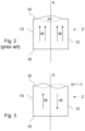
- Asymmetric vibrations will also convert the acoustically efficient monopole-like mode to a much less efficient dipole-type of mode, as will be explained in conjunction with Fig. 2 and Fig. 3 , which show symmetric and asymmetric vibration modes, respectively, and further explain the sound producing properties thereof.
- Fig. 2 conceptually shows a symmetric mode acting on the first yoke 16 of a prior art traction reactor 2' of the prior art reactor core 1'.
- first yoke 16 For clarity of the drawing, only the forces acting on the first yoke 16 are shown. However, similar forces/movements can also be observed on the first limb 10, the second limb 12 and on the second yoke 18. It can be seen that a certain volume of a surrounding medium, ⁇ V (positive or negative), is displaced as the first yoke 16 vibrates. This displacement radiates noise to the audible far field, which may be perceived as disturbing noise.
- ⁇ V positive or negative
- asymmetric vibration mode shown in Fig. 3 which is achieved by a reactor core 1 and a traction reactor 2 according to the present disclosure, moves one part of the first yoke 16 up as another part is moved down, theoretically resulting in a net volume displacement, ⁇ V, equal to zero.
- ⁇ V net volume displacement
- Such an asymmetric vibration mode radiates noise to the near field, which is not audible at a distance. In other words, it is not perceived as disturbing noise.
- the centre plane A is shown in Fig. 2 and Fig. 3 .
- FIG. 2 illustrate how every portion of the first yoke 16 of the prior art traction reactor 2', located on opposite sides of the center plane A, are displaced in the same direction at the same time for displacements in directions parallel to the center plane A.
- Fig. 3 illustrating the traction reactor 2 according to the present disclosure, the asymmetric vibration mode results in opposing directions M, -M on opposite sides of the center plane A.
- Fig. 3 only the forces acting on the first yoke 16 are shown in Fig. 3 .
- similar forces/movements can also be observed on the first limb 10, the second limb 12 and on the second yoke 18.
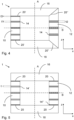
- Fig. 4 - Fig. 7 illustrate example embodiments of a reactor core 1 for a traction reactor 2 according to the present disclosure.
- the reactor core 1 has an extension along a first axis z, a second axis x and a third axis y (not shown), the first axis z, the second axis (x) and the third axis y are orthogonal to each other.
- the reactor core 1 is divided in half, as seen along the second axis x, at a first center plane A extending along the first axis z and along the third axis y.
- the reactor core 1 is also divided in half, as seen along the first axis z, at a second center plane B extending along the second axis x and along the third axis y.
- the reactor core 1 comprises a first limb 10 and a second limb 12.
- the first limb 10 and the second limb 12 extend in parallel with the first axis z and are symmetrically arranged with regard to the first center plane A.
- the first limb 10 and the second limb 12 comprise a plurality of gaps 14 arranged transversally to the first axis z.
- the gaps 14 have individual thicknesses t as seen along the first axis z.
- a sum of individual thicknesses t of the plurality of gaps 14 of the first limb 10 and of the second limb 12 equals a predetermined nominal total thickness T.
- the reactor core 1 further comprises a first yoke 16 and a second yoke 18.
- the first yoke 16 and the second yoke 18 extend in parallel with the second axis x, and are symmetrically arranged with regard to the second center plane B.
- the reactor core 1 also comprises a plurality of connecting joints 20 formed by connections between the first yoke 16 and each of the first limb 10 and the second limb 12, and by connections between the second yoke 18 and each of the first limb 10 and the second limb 12.
- the example reactor cores 1 shown in Fig. 4 - Fig. 7 comprise an asymmetry with regard to the first center plane A and/or with regard to the second center plane B by an asymmetrical arrangement of the plurality of gaps 14, and/or by an asymmetrical arrangement of the plurality of connecting joints 20, with regard to the first center plane A and/or with regard to the second center plane B.
- the reactor core is made of a ferromagnetic material and comprises "gaps" 14.
- the gaps 14 are also known as air gaps 14.
- An air gap 14 is a non-magnetic part of the reactor core 1 and it is usually connected magnetically in series, which allows a substantial part of the magnetic flux to flow through the gaps 14.
- the gaps 14 comprised in the first limb 10 and the second limb 12 may be arranged normal (or transversally) to the first axis z.
- the nominal total thickness of the plurality of gaps 14 in all the limbs 10, 12 may, as an example, be 54 mm.
- the asymmetry with regard to the first center plane A and/or with regard to the second center plane B is a structural asymmetry.
- the structural asymmetry is a result of arranging the plurality of gaps 14 and/or the connecting joints 20 in a structurally asymmetric manner with regard to the first center plane A and/or with regard to the second center plane B.
- Such structural asymmetry may be achieved by selecting asymmetric positioning/locations of the gaps 14 and/or connecting joints 20, and/or by selecting properties of individual gaps 14 and/or of connecting joints 20 such that structural symmetry or symmetric force distribution is broken.
- the asymmetry transforms the monopole-like mode of vibration of an operating traction reactor 2 comprising the reactor core 1, into a less noise-efficient dipole-like mode of vibration, thereby reducing noise emissions from a traction reactor 2 comprising the reactor core 1.
- the plurality gaps 14 of the first limb 10 and of the second limb 12 may be asymmetrically arranged with regard to the first center plane A and/or with regard to the second center plane B. As such a number of gaps 14 comprised in the first limb 10 may differ from a number of gaps 14 comprised in the second limb 12. Individual thicknesses t of the gaps 14 comprised in the first limb 10 may differ from individual thicknesses t of the gaps 14 comprised in the second limb 12. In the present disclosure, the nominal total thickness is exemplified by 54 mm, i.e., the total thickness of all the gaps 14 comprised in the reactor core 1. In the prior art reactor core 1' shown in Fig.
- the gaps 14 are symmetrically positioned in with regard to the first center plane A.
- the gaps 14' at interfaces between the limbs and the yoke may be 1,5 mm, with two interface gaps 14' placed symmetrically on each side of the first center plane A.
- the remaining gaps 14' may be 8 mm, with three gaps 14' symmetrically located on each side of the center plane A, bringing the total thickness to 54 mm.
- the plurality of gaps 14 may comprise at least two different individual thicknesses t and the sum of individual thicknesses t of the plurality of gaps 14 of the first limb 10 and of the second limb 12 is maintained equal to the total nominal thickness T.
- the gaps 14 of the first limb 10 may have individual thicknesses denoted by t1, t2 and t3.
- the reactor core 1 may be made structurally asymmetric with regard to the first center plane A and/or with regard to the second center plane B without affecting the electromagnetic properties of a traction reactor 2 comprising the reactor core 1.
- each gap 14 of the plurality of gaps 14 of the first limb 10 and of the second limb 12 may comprise a material having a predetermined modulus of elasticity, affecting a first stiffness of the first limb 10 and a second stiffness of the second limb 12, respectively, as seen along the first axis z.
- the first stiffness of the first limb 10 and the second stiffness of the second limb 12 may be asymmetrically arranged with regard to the first center plane A and/or with regard to the second center plane B.
- the plurality of gaps 14 may comprise at least a first type of gaps 14' comprising a first material having a first modulus of elasticity and a second type of gaps 14" comprising a second material having a second modulus of elasticity.
- the first type of gaps 14' and the second type of gaps 14" are arranged such that the first stiffness of the first limb 10 and the second stiffness of the second limb 12 are asymmetrically arranged with regard to the first center plane A and/or with regard to the second center plane B.
- the material of the gaps 14 may thus affect the stiffness of the first limb 10 and of the second limb 12 and thereby provide a structural asymmetry to the reactor core 1 with regard to the first center plane A and/or with regard to the second center plane B.
- the reactor core 1 comprises a similar setup of gaps 14 as the prior art reactor core 1' of Fig. 1 .
- the first limb 10 of the example comprises three first-type gaps 14', and two second-type gaps 14" whereas the second limb 12 comprises five second-type gaps 14", causing a structural asymmetry with regard to the first center plane A.
- the stiffnesses of the first limb 10 and of the second limb 12 may be varied to produce a structural asymmetry of the reactor core 1 without altering the number of gaps 14 or the individual thicknesses t of the gaps 14.
- the stiffnesses of the first limb 10 and of the second limb 12 may be varied by a combination of different materials, individual thicknesses t and/or number of gaps 14 in the respective first and second limb 10, 12.
- the first material may be steatite and the second material may be a fiberglass thermoset composite laminate, such as G11.
- Steatite has a modulus of elasticity greater than 100 GPa and G11 has a modulus of elasticity of less than 25 GPa.
- the plurality of connecting joints 20 may comprises at least a first type of connecting joint 20' and a second type of connecting joint 20".
- the at least first type of connecting joint and the at least second type of connecting joint may be asymmetrically arranged with regard to the first center plane A and/or with regard to the second center plane B, as shown in Fig. 4 , Fig. 6 and Fig. 7 .
- the first type of connecting joint 20' is structurally different as compared to the second type of connecting joint 20".
- Different connecting joints 20 achieve different stiffnesses and differences in magnetic flux lines through the connecting joints. The latter may result in differences in magnetic forces acting on the reactor core 1.
- the structural asymmetry of the reactor core 1 may thus be provided by arranging the first type of connecting joint 20' and the second type of connecting joint 20" asymmetrically with regard to the first center plane A and/or with regard to the second center plane B.
- the at least first type of connecting joints 20' may comprise butt joints and the at least second type of connecting joints 20" may comprise step-lap joints.
- the second type of connecting joints 20" of the second limb 12, interfacing with the first yoke 16 and the second yoke 18, comprise the step-lap joints, which may cause an asymmetric force distribution in the reactor core 1 when arranged asymmetrically with regard to the first center plane A, as shown.
- the step-lap joints of the present disclosure comprise interfaces between the limbs and the yokes, which interfaces are parallel with the third axis y (not shown) and extending along the first axis z and extending along the second axis x. Step-lap joints give rise to different magnetic flux lines as compared to butt joints, resulting in differences in magnetic forces acting on the reactor core 1.
- a structural asymmetry is achieved by arranging two step-lap joints 20" at the interfaces between the second limb 12 and the first yoke 16 and the second yoke 18 on one side of the first center plane A, whereas two butt joints (first type of connecting joint 20') are arranged on the other side of the center plane A.
- the at least first type of connecting joints 20' may comprise butt joints, where interfacing surfaces of the first yoke 16 and/or the second yoke 18 with the first limb 10 and/or with the second limb 12 are parallel with the first center plane A.
- the at least second type of connecting joints 20" may also comprises butt joints, where interfacing surfaces of the first yoke 16 and/or the second yoke 18 with the first limb 10 and/or with the second limb 12 are parallel with the second center plane B.
- such first type of connecting joints 21' and second type of connecting joints 21" may be arranged asymmetrically with regard to the first center plane A and/or with regard to the second center plane B to achieve the intended structural asymmetry of the reactor core 1.
- Fig. 8 illustrates effects on noise radiation of example traction reactors 2' of the present disclosure compared to prior art traction reactors 2'.
- the vertical axis shows noise radiation W expressed in dB.
- a first curve 100 shows noise radiation of a prior art traction reactor 2'.
- a second curve 200 shows an example of asymmetrically arranged butt joints and steatite gap material.
- a third curve 300 shows an example of asymmetrically arranged step-lap joints and steatite material.
- a fourth curve 400 shows an example of asymmetrically arranged steatite material in one limb and butt joints. It can be seen that there is a significant reduction in noise radiation around 2500 Hz, i.e., at which frequency conventional traction reactors are usually prone to high noise radiation.
- traction reactors 2 according to the present disclosure provide a significantly improved sound environment for staff and passengers of a train set comprising the traction reactor 2.
- Fig. 9 shows a traction reactor 2 according to the second aspect of the disclosure
- the traction reactor 2 comprises the reactor core 1 of any one of the example embodiments of the first aspect of the disclosure.
- Each of the first limb 10 and the second limb 12 comprises a winding 22.
- Fig. 10 illustrates an electric power device 3 according to the third aspect of the disclosure.
- the electric power device 3 comprises the traction reactor 2 according to any one of the embodiments for the second aspect of the disclosure.
- the electric power device further comprises at least one traction converter 24 and a transformer 26.
- Fig. 10 further shows an electric train set 4 according to the fourth aspect of the disclosure.
- the electric train set comprises at least one electrically driven motor car 28 comprising the electric power device 3 according to anyone of the embodiments of the third aspect of the disclosure. In the example, two electric motor cars 28 are shown.
- Traction reactors 2 are located between the traction converters 24 and the transformer 26.
- a traction converter is fed with DC, which is converted to 50 Hz utility power.
- the traction converter 24 also produces harmonics because of pulse width modulation technique (PWM). Such harmonics need to be filtered out before reaching the transformer 26.
- Traction reactors 2 are applied to filter out the harmonics and send the 50Hz signal to the transformer 26.
- PWM pulse width modulation technique
Landscapes
- Engineering & Computer Science (AREA)
- Power Engineering (AREA)
- Chemical & Material Sciences (AREA)
- Composite Materials (AREA)
- Inverter Devices (AREA)
- Vibration Prevention Devices (AREA)
- Regulation Of General Use Transformers (AREA)
Abstract
A reactor core (1) for a traction reactor (2) of an electric power device (3), the reactor core (1) comprising a first limb (10) and a second limb (12) comprising a plurality of gaps (14), a first yoke (16) and a second yoke (18), a plurality of connecting joints (20) formed by connections between the first yoke (16) and each of the first limb (10) and the second limb (12), and by connections between the second yoke (18) and each of the first limb (10) and the second limb (12). The reactor core (1) further comprises an asymmetry with regard to a first center plane (A) and/or with regard to a second center plane (B) by an asymmetrical arrangement of the plurality of gaps (14), and/or by an asymmetrical arrangement of the plurality of connecting joints (20), with regard to the first center plane (A) and/or with regard to the second center plane (B).
Description
- The present disclosure relates to a reactor core for a traction reactor. In particular it relates to a reactor core and a traction reactor comprising the reactor core. In addition, it relates to an electric power device comprising the traction reactor and to an electric train set comprising the electric power device.
- Today's traction reactors are fully symmetric mechanical structures across three symmetry planes. When a core of the reactor is magnetically energized by currents running in a symmetric coil arrangement, symmetric force distributions develop.
- It has been shown by measurements and simulations that these two symmetry properties result in a strong excitation of a structural vibration mode which is particularly prone to high noise radiation, especially the three-fold symmetric mode around 2500 Hz. It is because of an acoustic monopole-like mode vibration pattern of the reactor core, arising from the symmetric mechanical structure and the symmetric force distribution, that the vibration mode exhibits a very high radiation efficiency.
- As an example, a traction reactor in operation in a motor car of a train is used for filtering out PWM switching harmonics originating from a train converter. Reactor vibrations and noise emissions frequently lead to a poor sound environment in the passenger and train staff compartments. Current ripple originating from the train converter exhibits high amplitudes around 2 kHz and this mode is likely the cause of noise and vibration problems encountered in such applications.
- Therefore, an object of the disclosure is to provide an improved reactor core for a traction reactor. More in particular, an object of the present disclosure is to provide a reactor core for a traction reactor where the core is structurally asymmetric with regard to at least one center plane of the reactor core.
- According to a first aspect of the present disclosure, the object is at least partly achieved by a reactor core according to
claim 1. - Hence, there is provided a reactor core for a traction reactor of an electric power device. The reactor core has an extension along a first axis, a second axis and a third axis. The first axis, the second axis and the third axis are orthogonal to each other. The reactor core is divided in half, as seen along the second axis, at a first center plane extending along the first axis and extending along the third axis. The reactor core is divided in half, as seen along the first axis, at a second center plane extending along the second axis and extending along the third axis.
- The reactor core comprises a first limb and a second limb. The first limb and the second limb extend in parallel with the first axis, are symmetrically arranged with regard to the first center plane and comprise a plurality of gaps arranged transversally to the first axis. The gaps have individual thicknesses as seen along the first axis. A sum of individual thicknesses of the plurality of gaps of the first limb and of the second limb equals a predetermined nominal total thickness of all gaps.
- The reactor core further comprises a first yoke and a second yoke. The first yoke and the second yoke extend in parallel with the second axis and are symmetrically arranged with regard to the second center plane.
- The reactor core further comprises a plurality of connecting joints formed by connections between the first yoke and each of the first limb and the second limb, and by connections between the second yoke and each of the first limb and the second limb.
- The reactor core comprises an asymmetry with regard to the first center plane and/or with regard to the second center plane, which asymmetry results from an asymmetrical arrangement of the plurality of gaps, and/or from an asymmetrical arrangement of the plurality of connecting joints, with regard to the first center plane and/or with regard to the second center plane.
- The "gaps" are also known as air gaps. An air gap is a non-magnetic part of the reactor core, and it is usually connected magnetically in series, which allows a substantial part of the magnetic flux to flow through the gap. The gaps comprised in the first limb and the second limb may be arranged normal (or transversally) to the first axis. The nominal total thickness of the plurality of gaps in all the limbs may, as an example, be 54 mm.
- The asymmetry with regard to the first center plane and/or with regard to the second center plane is a structural asymmetry. The structural asymmetry is a result of arranging the plurality of gaps and/or the connecting joints in a structurally asymmetric manner with regard to the first center plane and/or with regard to the second center plane. The asymmetry transforms the monopole-like mode of vibration of an operating traction reactor comprising the reactor core, into a less noise-efficient dipole-like mode of vibration, thereby reducing noise emissions from a traction reactor comprising the reactor core.
- Optionally, the plurality gaps of the first limb and the second limb are asymmetrically arranged with regard to the first center plane and/or with regard to the second center plane.
- As such a number of gaps comprised in the first limb may differ from a number of gaps comprised in the second limb. Individual thicknesses of the gaps comprised in the first limb may differ from individual thicknesses of the gaps comprised in the second limb.
- Optionally, the plurality of gaps comprises at least two different individual thicknesses and the sum of individual thicknesses of the plurality of gaps of the first limb and of the second limb is maintained equal to the total nominal thickness.
- In order to maintain the electromagnetic properties and function of a traction reactor comprising the inventive reactor core, the total thickness of the plurality of gaps should be maintained equal to the nominal total thickness. Thereby, the reactor core may be made structurally asymmetric with regard to the first center plane and/or with regard to the second center plane without affecting the function of a traction reactor comprising the reactor core. Since an extension of a limb is constant, varying the thicknesses of the gaps comprised in the limb may affect the stiffness of the limb. A limb with more gaps would be less than a stiffness of a limb having less gaps. The number of gaps and/or the thicknesses of the gaps may accordingly be varied to achieve different stiffnesses in different limbs.
- Optionally, each gap of the plurality of gaps of the first limb and of the second limb comprises a material having a predetermined modulus of elasticity, affecting a first stiffness of the first limb and a second stiffness of the second limb, respectively, as seen along the first axis. The first stiffness of the first limb and the second stiffness of the second limb are asymmetrically arranged with regard to the first center plane and/or with regard to the second center plane.
- The material of the gaps may thus affect the stiffness of the first limb and of the second limb and thereby provide a structural asymmetry to the reactor core with regard to the first center plane and/or with regard to the second center plane.
- Optionally, the plurality of gaps comprises at least a first type of gaps comprising a first material having a first modulus of elasticity and a second type of gaps comprising a second material having a second modulus of elasticity. The first type of gaps and the second type of gaps are arranged such that the first stiffness of the first limb and the second stiffness of the second limb are asymmetrically arranged with regard to the first center plane and/or with regard to the second center plane.
- Thereby, by providing gaps with different materials, the stiffnesses of the first limb and of the second limb may be varied to produce a structural asymmetry of the reactor core without altering the number of gaps or the individual thicknesses of the gaps. Or the stiffnesses of the first limb and of the second limb may be varied as a combination of different materials, individual thicknesses and/or number of gaps in the respective limb.
- Optionally, the first material is steatite, and the second material is a fiberglass thermoset composite laminate, such as G11. Steatite has a modulus of elasticity greater than 100 GPa and G11 has a modulus of elasticity of less than 25 GPa.
- Optionally, the plurality of connecting joints comprises at least a first type of connecting joint and a second type of connecting joint. The at least first type of connecting joint and the at least second type of connecting joint are asymmetrically arranged with regard to the first center plane and/or with regard to the second center plane.
- The first type of connecting joint is structurally different as compared to the second type of connecting joint. Different connecting joints affect the magnetic flux lines, resulting in differences in magnetic forces at different connecting joints. The structural asymmetry of the reactor core may thus be provided by arranging the first type of connecting joint and the second type of connecting joint asymmetrically with regard to the first center plane and/or with regard to the second center plane. Optionally, the at least first type of connecting joints comprises butt joints and the at least second type of connecting joints comprises step-lap joints.
- Optionally, the at least first type of connecting joints comprises butt joints, where interfacing surfaces of the first yoke and/or the second yoke with the first limb and/or with the second limb are parallel with the first center plane. The at least second type of connecting joints comprises butt joints, where interfacing surfaces of the first yoke and/or the second yoke with the first limb and/or with the second limb are parallel with the second center plane.
- According to a second aspect of the present disclosure, the object is at least partly achieved by a traction reactor according to
claim 10. - Hence, there is provided a traction reactor comprising the reactor core of any one of the embodiments for the first aspect of the disclosure, and wherein each of the first limb and the second limb comprises a winding.
- Such a traction reactor, having a structurally asymmetric reactor core with regard to the first center plane and/or with regard to the second center plane, thus has less efficient noise radiation properties as compared to prior art traction reactors.
- According to a third aspect of the present disclosure, the object is at least partly achieved by an electric power device according to claim 11.
- Hence, there is provided an electric power device comprising the traction reactor according to any one of the embodiments of the second aspect of the disclosure. The power device further comprises at least one traction converter and a transformer.
- According to a fourth aspect of the present disclosure, the object is at least partly achieved by an electric train set according to
claim 12. - Hence, there is provided an electric train set comprising at least one electrically driven motor car comprising the electric power device according to any one of the embodiments of the third aspect of the disclosure.
- Thereby, a motor car is provided offering an improved sound environment for passenger and train staff compartments.
- The above aspects, accompanying claims, and/or examples disclosed herein above and later below may be suitably combined with each other as would be apparent to anyone of ordinary skill in the art.
- Additional features and advantages are disclosed in the following description, claims, and drawings, and in part will be readily apparent therefrom to those skilled in the art or recognized by practicing the disclosure as described herein.
- Further objects and advantages of, and features of the disclosure will be apparent from the following description of one or more embodiments, with reference to the appended drawings, where:
- Fig. 1
- shows a prior art traction reactor core.
- Fig. 2
- shows a monopole-like vibration mode of a prior art traction reactor.
- Fig. 3
- shows a dipole-like vibration mode of a traction reactor according the second aspect of the present disclosure.
- Fig. 4
- shows a reactor core according to an example of the first aspect of the present disclosure.
- Fig. 5
- shows a reactor core according to an example of the first aspect of the present disclosure.
- Fig. 6
- shows a reactor core according to an example of the first aspect of the present disclosure.
- Fig. 7
- shows a reactor core according to an example of the first aspect of the present disclosure.
- Fig. 8
- shows a comparison of noise radiation between a prior art traction reactor and traction reactors according to examples of the present disclosure.
- Fig. 9
- shows a traction reactor according to the second aspect of the present disclosure.
- Fig. 10
- shows electric power devices according to the third aspect of the present disclosure and an electric train set according to the fourth aspect of the disclosure.
- The present disclosure is developed in more detail below referring to the appended drawings which show examples of embodiments. The disclosure should not be viewed as limited to the described examples of embodiments. Like numbers refer to like elements throughout the description.
- The terminology used herein is for the purpose of describing particular aspects of the disclosure only and is not intended to limit the invention. As used herein, the singular forms "a", "an" and "the" are intended to include the plural forms as well, unless the context clearly indicates otherwise. Unless otherwise defined, all terms (including technical and scientific terms) used herein have the same meaning as commonly understood by one of ordinary skill in the art to which this disclosure belongs.
- Electric devices, such as transformers, reactors, etc, as any other industrial products, must comply with various requirements on noise levels. It is known to people skilled in the art that the acoustic power P emitted from a vibrating structure acted upon by forces F can be expressed

- As an example of an electric device generating high noise levels,
Fig. 1 shows a prior art reactor core 1' for a prior art traction reactor. The prior art reactor core 1' has an extension along a first axis z, a second axis x and a third axis y (not shown), the first axis z, the second axis (x) and the third axis y are orthogonal to each other. The prior art reactor core 1' is divided in half, as seen along the second axis x, at a first center plane A extending along the first axis z and along the third axis y. The prior art reactor core 1' is also divided in half, as seen along the first axis z, at a second center plane B extending along the second axis x and along the third axis y. - The prior art reactor core 1' comprises a
first limb 10 and asecond limb 12. Thefirst limb 10 and thesecond limb 12 extend in parallel with the first axis z and are symmetrically arranged with regard to the first center plane A. Thefirst limb 10 and thesecond limb 12 comprise a plurality of gaps 14' arranged transversally to the first axis z. The gaps 14' have individual thicknesses t as seen along the first axis z. A sum of individual thicknesses t of the plurality of gaps 14' of thefirst limb 10 and of thesecond limb 12 equals a predetermined nominal total thickness T. - The prior art reactor core 1' further comprises a
first yoke 16 and asecond yoke 18. Thefirst yoke 16 and thesecond yoke 18 extend in parallel with the second axis x, and are symmetrically arranged with regard to the second center plane B. - The prior art reactor core 1' also comprises a plurality of connecting joints 20' formed by connections between the
first yoke 16 and each of thefirst limb 10 and thesecond limb 12, and by connections between thesecond yoke 18 and each of thefirst limb 10 and thesecond limb 12. The connecting joints 20' and the gaps 14' are all symmetrically arranged with regard to the first center plane A and/or the second center plane B. - As discussed in the Background Section, prior art traction reactors are fully symmetric mechanical structures across three symmetry planes. Planes A and B are shown in
Fig. 1 . When a core of the reactor is magnetically energized by currents running in a symmetric coil arrangement, symmetric force distributions develop, which result in vibrations of significant acoustic power. - It has been shown by measurements and simulations that these two symmetry properties (symmetric structure and symmetric force distribution) result in a strong excitation of a structural vibration mode which is particularly prone to high noise radiation, especially the three-fold symmetric mode around 2500 Hz.
- The present disclosure aims at breaking the structural symmetry of the reactor core by introducing a structural asymmetry with regard to the first center plane A and/or with regard to the second center plane B. The structural asymmetry is achieved by arranging the plurality of gaps (air gaps) and/or the connecting joints - or the properties of the gaps and connecting joints - asymmetrically with regard to the first center plane A and/or with regard to the second center plane B.
- Changes to gap properties may bring about beneficial asymmetric mode shapes, whereas mixing butt and step-lap joints may also result in distorting symmetric electrodynamic force distributions, in addition to also influencing mechanical resonance properties.
- Asymmetric vibrations will also convert the acoustically efficient monopole-like mode to a much less efficient dipole-type of mode, as will be explained in conjunction with
Fig. 2 and Fig. 3 , which show symmetric and asymmetric vibration modes, respectively, and further explain the sound producing properties thereof. -
Fig. 2 conceptually shows a symmetric mode acting on thefirst yoke 16 of a prior art traction reactor 2' of the prior art reactor core 1'. For clarity of the drawing, only the forces acting on thefirst yoke 16 are shown. However, similar forces/movements can also be observed on thefirst limb 10, thesecond limb 12 and on thesecond yoke 18. It can be seen that a certain volume of a surrounding medium, ΔV (positive or negative), is displaced as thefirst yoke 16 vibrates. This displacement radiates noise to the audible far field, which may be perceived as disturbing noise. - In contrast, the asymmetric vibration mode shown in
Fig. 3 which is achieved by areactor core 1 and atraction reactor 2 according to the present disclosure, moves one part of thefirst yoke 16 up as another part is moved down, theoretically resulting in a net volume displacement, ΔV, equal to zero. Such an asymmetric vibration mode radiates noise to the near field, which is not audible at a distance. In other words, it is not perceived as disturbing noise. The centre plane A is shown inFig. 2 and Fig. 3 . The arrows M inFig. 2 illustrate how every portion of thefirst yoke 16 of the prior art traction reactor 2', located on opposite sides of the center plane A, are displaced in the same direction at the same time for displacements in directions parallel to the center plane A. InFig. 3 , illustrating thetraction reactor 2 according to the present disclosure, the asymmetric vibration mode results in opposing directions M, -M on opposite sides of the center plane A. Similarly toFig. 2 , only the forces acting on thefirst yoke 16 are shown inFig. 3 . However, similar forces/movements can also be observed on thefirst limb 10, thesecond limb 12 and on thesecond yoke 18. -
Fig. 4 - Fig. 7 illustrate example embodiments of areactor core 1 for atraction reactor 2 according to the present disclosure. In the illustrated examples, thereactor core 1 has an extension along a first axis z, a second axis x and a third axis y (not shown), the first axis z, the second axis (x) and the third axis y are orthogonal to each other. Thereactor core 1 is divided in half, as seen along the second axis x, at a first center plane A extending along the first axis z and along the third axis y. Thereactor core 1 is also divided in half, as seen along the first axis z, at a second center plane B extending along the second axis x and along the third axis y. - The
reactor core 1 comprises afirst limb 10 and asecond limb 12. Thefirst limb 10 and thesecond limb 12 extend in parallel with the first axis z and are symmetrically arranged with regard to the first center plane A. Thefirst limb 10 and thesecond limb 12 comprise a plurality ofgaps 14 arranged transversally to the first axis z. Thegaps 14 have individual thicknesses t as seen along the first axis z. A sum of individual thicknesses t of the plurality ofgaps 14 of thefirst limb 10 and of thesecond limb 12 equals a predetermined nominal total thickness T. - The
reactor core 1 further comprises afirst yoke 16 and asecond yoke 18. Thefirst yoke 16 and thesecond yoke 18 extend in parallel with the second axis x, and are symmetrically arranged with regard to the second center plane B. - The
reactor core 1 also comprises a plurality of connectingjoints 20 formed by connections between thefirst yoke 16 and each of thefirst limb 10 and thesecond limb 12, and by connections between thesecond yoke 18 and each of thefirst limb 10 and thesecond limb 12. - The
example reactor cores 1 shown inFig. 4 - Fig. 7 comprise an asymmetry with regard to the first center plane A and/or with regard to the second center plane B by an asymmetrical arrangement of the plurality ofgaps 14, and/or by an asymmetrical arrangement of the plurality of connectingjoints 20, with regard to the first center plane A and/or with regard to the second center plane B. - The reactor core is made of a ferromagnetic material and comprises "gaps" 14. The
gaps 14 are also known asair gaps 14. Anair gap 14 is a non-magnetic part of thereactor core 1 and it is usually connected magnetically in series, which allows a substantial part of the magnetic flux to flow through thegaps 14. Thegaps 14 comprised in thefirst limb 10 and thesecond limb 12 may be arranged normal (or transversally) to the first axis z. The nominal total thickness of the plurality ofgaps 14 in all thelimbs - The asymmetry with regard to the first center plane A and/or with regard to the second center plane B is a structural asymmetry. The structural asymmetry is a result of arranging the plurality of
gaps 14 and/or the connectingjoints 20 in a structurally asymmetric manner with regard to the first center plane A and/or with regard to the second center plane B. Such structural asymmetry may be achieved by selecting asymmetric positioning/locations of thegaps 14 and/or connectingjoints 20, and/or by selecting properties ofindividual gaps 14 and/or of connectingjoints 20 such that structural symmetry or symmetric force distribution is broken. The asymmetry transforms the monopole-like mode of vibration of an operatingtraction reactor 2 comprising thereactor core 1, into a less noise-efficient dipole-like mode of vibration, thereby reducing noise emissions from atraction reactor 2 comprising thereactor core 1. - The
plurality gaps 14 of thefirst limb 10 and of thesecond limb 12 may be asymmetrically arranged with regard to the first center plane A and/or with regard to the second center plane B. As such a number ofgaps 14 comprised in thefirst limb 10 may differ from a number ofgaps 14 comprised in thesecond limb 12. Individual thicknesses t of thegaps 14 comprised in thefirst limb 10 may differ from individual thicknesses t of thegaps 14 comprised in thesecond limb 12. In the present disclosure, the nominal total thickness is exemplified by 54 mm, i.e., the total thickness of all thegaps 14 comprised in thereactor core 1. In the prior art reactor core 1' shown inFig. 1 , thegaps 14 are symmetrically positioned in with regard to the first center plane A. In prior art, the gaps 14' at interfaces between the limbs and the yoke may be 1,5 mm, with two interface gaps 14' placed symmetrically on each side of the first center plane A. The remaining gaps 14' may be 8 mm, with three gaps 14' symmetrically located on each side of the center plane A, bringing the total thickness to 54 mm. - According to the present disclosure, the plurality of
gaps 14 may comprise at least two different individual thicknesses t and the sum of individual thicknesses t of the plurality ofgaps 14 of thefirst limb 10 and of thesecond limb 12 is maintained equal to the total nominal thickness T. As exemplified inFig. 4 , thegaps 14 of thefirst limb 10 may have individual thicknesses denoted by t1, t2 and t3. - As mentioned above, the total thickness of the plurality of
gaps 14 should be maintained equal to the nominal total thickness T. Thereby, thereactor core 1 may be made structurally asymmetric with regard to the first center plane A and/or with regard to the second center plane B without affecting the electromagnetic properties of atraction reactor 2 comprising thereactor core 1. - In the example of
Fig. 4 , the arrangement is asymmetrical in that fivegaps 14 are arranged on one side of the center plane A, along thefirst limb 10, comprising two interface gaps of t3=1,5 mm and three gaps of t1=8 mm. Thesecond limb 12, on the other side of the center plane A, is arranged with threegaps 14 of t2=9 mm. Thereby, thereactor core 1 is structurally asymmetric with regard to the first center plane A and the total thickness of the plurality ofgaps 14 is kept equal to the total nominal thickness T of 54 mm. - In another example, shown in
Fig. 5 , eachgap 14 of the plurality ofgaps 14 of thefirst limb 10 and of thesecond limb 12 may comprise a material having a predetermined modulus of elasticity, affecting a first stiffness of thefirst limb 10 and a second stiffness of thesecond limb 12, respectively, as seen along the first axis z. The first stiffness of thefirst limb 10 and the second stiffness of thesecond limb 12 may be asymmetrically arranged with regard to the first center plane A and/or with regard to the second center plane B. - The plurality of
gaps 14 may comprise at least a first type of gaps 14' comprising a first material having a first modulus of elasticity and a second type ofgaps 14" comprising a second material having a second modulus of elasticity. The first type of gaps 14' and the second type ofgaps 14" are arranged such that the first stiffness of thefirst limb 10 and the second stiffness of thesecond limb 12 are asymmetrically arranged with regard to the first center plane A and/or with regard to the second center plane B. - The material of the
gaps 14 may thus affect the stiffness of thefirst limb 10 and of thesecond limb 12 and thereby provide a structural asymmetry to thereactor core 1 with regard to the first center plane A and/or with regard to the second center plane B. In the example ofFig. 5 , thereactor core 1 comprises a similar setup ofgaps 14 as the prior art reactor core 1' ofFig. 1 . However, thefirst limb 10 of the example comprises three first-type gaps 14', and two second-type gaps 14" whereas thesecond limb 12 comprises five second-type gaps 14", causing a structural asymmetry with regard to the first center plane A. - Thereby, by providing
gaps 14 with different materials, the stiffnesses of thefirst limb 10 and of thesecond limb 12 may be varied to produce a structural asymmetry of thereactor core 1 without altering the number ofgaps 14 or the individual thicknesses t of thegaps 14. Alternatively, the stiffnesses of thefirst limb 10 and of thesecond limb 12 may be varied by a combination of different materials, individual thicknesses t and/or number ofgaps 14 in the respective first andsecond limb - As an example, the first material may be steatite and the second material may be a fiberglass thermoset composite laminate, such as G11. Steatite has a modulus of elasticity greater than 100 GPa and G11 has a modulus of elasticity of less than 25 GPa.
- The plurality of connecting
joints 20 may comprises at least a first type of connecting joint 20' and a second type of connecting joint 20". The at least first type of connecting joint and the at least second type of connecting joint may be asymmetrically arranged with regard to the first center plane A and/or with regard to the second center plane B, as shown inFig. 4 ,Fig. 6 and Fig. 7 . - The first type of connecting joint 20' is structurally different as compared to the second type of connecting joint 20". Different connecting
joints 20 achieve different stiffnesses and differences in magnetic flux lines through the connecting joints. The latter may result in differences in magnetic forces acting on thereactor core 1. The structural asymmetry of thereactor core 1 may thus be provided by arranging the first type of connecting joint 20' and the second type of connecting joint 20" asymmetrically with regard to the first center plane A and/or with regard to the second center plane B. - The at least first type of connecting joints 20' may comprise butt joints and the at least second type of connecting
joints 20" may comprise step-lap joints. - As exemplified in
Fig. 4 , the second type of connectingjoints 20" of thesecond limb 12, interfacing with thefirst yoke 16 and thesecond yoke 18, comprise the step-lap joints, which may cause an asymmetric force distribution in thereactor core 1 when arranged asymmetrically with regard to the first center plane A, as shown. The step-lap joints of the present disclosure comprise interfaces between the limbs and the yokes, which interfaces are parallel with the third axis y (not shown) and extending along the first axis z and extending along the second axis x. Step-lap joints give rise to different magnetic flux lines as compared to butt joints, resulting in differences in magnetic forces acting on thereactor core 1. In the example ofFig. 4 , a structural asymmetry is achieved by arranging two step-lap joints 20" at the interfaces between thesecond limb 12 and thefirst yoke 16 and thesecond yoke 18 on one side of the first center plane A, whereas two butt joints (first type of connecting joint 20') are arranged on the other side of the center plane A. - Alternatively, the at least first type of connecting joints 20' may comprise butt joints, where interfacing surfaces of the
first yoke 16 and/or thesecond yoke 18 with thefirst limb 10 and/or with thesecond limb 12 are parallel with the first center plane A. The at least second type of connectingjoints 20" may also comprises butt joints, where interfacing surfaces of thefirst yoke 16 and/or thesecond yoke 18 with thefirst limb 10 and/or with thesecond limb 12 are parallel with the second center plane B. As exemplified inFig. 6 and Fig. 7 , such first type of connecting joints 21' and second type of connecting joints 21" may be arranged asymmetrically with regard to the first center plane A and/or with regard to the second center plane B to achieve the intended structural asymmetry of thereactor core 1. -
Fig. 8 illustrates effects on noise radiation of example traction reactors 2' of the present disclosure compared to prior art traction reactors 2'. The vertical axis shows noise radiation W expressed in dB. Afirst curve 100 shows noise radiation of a prior art traction reactor 2'. Asecond curve 200 shows an example of asymmetrically arranged butt joints and steatite gap material. Athird curve 300 shows an example of asymmetrically arranged step-lap joints and steatite material. Afourth curve 400 shows an example of asymmetrically arranged steatite material in one limb and butt joints. It can be seen that there is a significant reduction in noise radiation around 2500 Hz, i.e., at which frequency conventional traction reactors are usually prone to high noise radiation. In other words,traction reactors 2 according to the present disclosure provide a significantly improved sound environment for staff and passengers of a train set comprising thetraction reactor 2. -
Fig. 9 shows atraction reactor 2 according to the second aspect of the disclosure, thetraction reactor 2 comprises thereactor core 1 of any one of the example embodiments of the first aspect of the disclosure. Each of thefirst limb 10 and thesecond limb 12 comprises a winding 22. Such atraction reactor 2, having a structurallyasymmetric reactor core 1 with regard to the first center A plane and/or with regard to the second center plane B, thus has less efficient noise radiation properties as compared to prior art traction reactors 2'. -
Fig. 10 illustrates anelectric power device 3 according to the third aspect of the disclosure. Theelectric power device 3 comprises thetraction reactor 2 according to any one of the embodiments for the second aspect of the disclosure. The electric power device further comprises at least onetraction converter 24 and atransformer 26. -
Fig. 10 further shows anelectric train set 4 according to the fourth aspect of the disclosure. The electric train set comprises at least one electrically drivenmotor car 28 comprising theelectric power device 3 according to anyone of the embodiments of the third aspect of the disclosure. In the example, twoelectric motor cars 28 are shown. -
Traction reactors 2 are located between thetraction converters 24 and thetransformer 26. A traction converter is fed with DC, which is converted to 50 Hz utility power. However, thetraction converter 24 also produces harmonics because of pulse width modulation technique (PWM). Such harmonics need to be filtered out before reaching thetransformer 26.Traction reactors 2 are applied to filter out the harmonics and send the 50Hz signal to thetransformer 26.
Claims (12)
- A reactor core (1) for a traction reactor (2) of an electric power device (3), said reactor core (1) having an extension along a first axis (z), a second axis (x) and a third axis (y), the first axis (z), the second axis (x) and the third axis (y) being orthogonal to each other, the reactor core (1) being divided in half, as seen along the second axis (x), at a first center plane (A) extending along the first axis (z) and extending along the third axis (y), the reactor core (1) being divided in half, as seen along the first axis (z), at a second center plane (B) extending along the second axis (x) and extending along the third axis (y), the reactor core (1) comprising:- a first limb (10) and a second limb (12), wherein the first limb (10) and the second limb (12) extend in parallel with the first axis (z), are symmetrically arranged with regard to the first center plane (A), and comprise a plurality of gaps (14) arranged transversally to the first axis (z), the gaps (14) having individual thicknesses (t) as seen along the first axis (z), and where a sum of individual thicknesses (t) of the plurality of gaps (14) of the first limb (10) and of the second limb (12) equals a predetermined nominal total thickness (T),- a first yoke (16) and a second yoke (18), wherein the first yoke (16) and the second yoke (18) extend in parallel with the second axis (x), and are symmetrically arranged with regard to the second center plane (B),- a plurality of connecting joints (20) formed by connections between the first yoke (16) and each of the first limb (10) and the second limb (12), and by connections between the second yoke (18) and each of the first limb (10) and the second limb (12), andwherein the reactor core (1) comprises an asymmetry with regard to the first center plane (A) and/or with regard to the second center plane (B) by an asymmetrical arrangement of the plurality of gaps (14), and/or by an asymmetrical arrangement of the plurality of connecting joints (20), with regard to the first center plane (A) and/or with regard to the second center plane (B).
- The reactor core (1) of claim 1, wherein the plurality gaps (14) of the first limb (10) and the second limb (12) are asymmetrically arranged with regard to the first center plane (A) and/or with regard to the second center plane (B).
- The reactor core (1) of claim 2, wherein the plurality of gaps (14) comprises at least two different individual thicknesses (t) and wherein the sum of individual thicknesses (t) of the plurality of gaps (14) of the first limb (10) and of the second limb (12) is maintained equal to the total nominal thickness (T).
- The reactor core (1) of any one of the previous claims, wherein each gap (14) of the plurality of gaps (14) of the first limb (10) and of the second limb (12) comprises a material having a predetermined modulus of elasticity, affecting a first stiffness of the first limb (10) and a second stiffness of the second limb (12), respectively, as seen along the first axis (z), and wherein the first stiffness of the first limb (10) and the second stiffness of the second limb (12) are asymmetrically arranged with regard to the first center plane (A) and/or with regard to the second center plane (B).
- The reactor core (1) of claim 4, wherein the plurality of gaps (14) comprises at least a first type of gaps (14') comprising a first material having a first modulus of elasticity and a second type of gaps (14") comprising a second material having a second modulus of elasticity, and wherein the first type of gaps (14') and the second type of gaps (14") are arranged such that the first stiffness of the first limb (10) and the second stiffness of the second limb (12) are asymmetrically arranged with regard to the first center plane (A) and/or with regard to the second center plane (B).
- The reactor core (1) of claim 5, wherein the first material is steatite, and the second material is a fiberglass thermoset composite laminate, such as G11.
- The reactor core (1) of any one of the previous claims, wherein the plurality of connecting joints (20) comprises at least a first type of connecting joint (20') and a second type of connecting joint (20") and wherein the at least first type of connecting joint (20') and the at least second type of connecting joint (20") are asymmetrically arranged with regard to the first center plane (A) and/or with regard to the second center plane (B).
- The reactor core (1) of claim 7, wherein the at least first type of connecting joints (20') comprises butt joints and the at least second type of connecting joints (20") comprises step-lap joints.
- The reactor core (1) of claim 7, wherein the at least first type of connecting joints (20') comprises butt joints wherein interfacing surfaces of the first yoke (16) and/or the second yoke (18) with the first limb (10) and/or with the second limb (12) are parallel with the first center plane (A) and wherein the at least second type of connecting joints (20") comprises butt joints wherein interfacing surfaces of the first yoke (16) and/or the second yoke (18) with the first limb (10) and/or with the second limb (12) are parallel with the second center plane (B).
- A traction reactor (2) comprising the reactor core (1) of any one of the claims 1-9, wherein each of the first limb (10) and the second limb (12) comprises a winding (22).
- An electric power device (3) comprising the traction reactor (2) according to claim 10, and further comprising at least one traction converter (24) and a transformer (26).
- An electric train set (4) comprising at least one electrically driven motor car (28) comprising the electric power device (3) according to claim 11.
Priority Applications (3)
| Application Number | Priority Date | Filing Date | Title |
|---|---|---|---|
| EP23186562.7A EP4495964A1 (en) | 2023-07-19 | 2023-07-19 | A reactor core, a traction reactor, an electric power device and an electric train set |
| PCT/EP2024/069407 WO2025016816A1 (en) | 2023-07-19 | 2024-07-09 | A reactor core, a traction reactor, an electric power device and an electric train set |
| CN202480048033.5A CN121532839A (en) | 2023-07-19 | 2024-07-09 | Reactor cores, traction reactors, power units and electric train sets |
Applications Claiming Priority (1)
| Application Number | Priority Date | Filing Date | Title |
|---|---|---|---|
| EP23186562.7A EP4495964A1 (en) | 2023-07-19 | 2023-07-19 | A reactor core, a traction reactor, an electric power device and an electric train set |
Publications (1)
| Publication Number | Publication Date |
|---|---|
| EP4495964A1 true EP4495964A1 (en) | 2025-01-22 |
Family
ID=87426905
Family Applications (1)
| Application Number | Title | Priority Date | Filing Date |
|---|---|---|---|
| EP23186562.7A Pending EP4495964A1 (en) | 2023-07-19 | 2023-07-19 | A reactor core, a traction reactor, an electric power device and an electric train set |
Country Status (3)
| Country | Link |
|---|---|
| EP (1) | EP4495964A1 (en) |
| CN (1) | CN121532839A (en) |
| WO (1) | WO2025016816A1 (en) |
Citations (5)
| Publication number | Priority date | Publication date | Assignee | Title |
|---|---|---|---|---|
| GB356066A (en) * | 1929-12-23 | 1931-09-03 | British Thomson Houston Co Ltd | Improvements in and relating to magnetic cores |
| GB686873A (en) * | 1949-12-22 | 1953-02-04 | British Thomson Houston Co Ltd | Improvements in and relating to laminated magnetic cores |
| GB717997A (en) * | 1951-08-07 | 1954-11-03 | Smit & Willem & Co Nv | Improvements in and relating to laminated magnetic core structures |
| JP2006351679A (en) * | 2005-06-14 | 2006-12-28 | Sumitomo Electric Ind Ltd | Reactor device |
| US20100171580A1 (en) * | 2007-01-15 | 2010-07-08 | Toru Abe | Reactor core and reactor |
Family Cites Families (2)
| Publication number | Priority date | Publication date | Assignee | Title |
|---|---|---|---|---|
| DE102011107252A1 (en) * | 2011-07-14 | 2013-01-17 | Schneider Electric Sachsenwerk Gmbh | Coil for current limitation |
| JP2017139397A (en) * | 2016-02-05 | 2017-08-10 | スミダコーポレーション株式会社 | Magnetic parts |
-
2023
- 2023-07-19 EP EP23186562.7A patent/EP4495964A1/en active Pending
-
2024
- 2024-07-09 CN CN202480048033.5A patent/CN121532839A/en active Pending
- 2024-07-09 WO PCT/EP2024/069407 patent/WO2025016816A1/en not_active Ceased
Patent Citations (5)
| Publication number | Priority date | Publication date | Assignee | Title |
|---|---|---|---|---|
| GB356066A (en) * | 1929-12-23 | 1931-09-03 | British Thomson Houston Co Ltd | Improvements in and relating to magnetic cores |
| GB686873A (en) * | 1949-12-22 | 1953-02-04 | British Thomson Houston Co Ltd | Improvements in and relating to laminated magnetic cores |
| GB717997A (en) * | 1951-08-07 | 1954-11-03 | Smit & Willem & Co Nv | Improvements in and relating to laminated magnetic core structures |
| JP2006351679A (en) * | 2005-06-14 | 2006-12-28 | Sumitomo Electric Ind Ltd | Reactor device |
| US20100171580A1 (en) * | 2007-01-15 | 2010-07-08 | Toru Abe | Reactor core and reactor |
Also Published As
| Publication number | Publication date |
|---|---|
| WO2025016816A1 (en) | 2025-01-23 |
| CN121532839A (en) | 2026-02-13 |
Similar Documents
| Publication | Publication Date | Title |
|---|---|---|
| US9537389B2 (en) | Inverter device, transformer, and transformer manufacturing method | |
| EP0957658B1 (en) | Thin electromagnetic transducer | |
| EP3193345A1 (en) | Multi-pulse electromagnetic device including a linear magnetic core configuration | |
| WO2001080408A1 (en) | Permanent magnet synchronous linear motor | |
| WO2012156675A1 (en) | Loudspeaker with force cancelling configuration | |
| CN102934337A (en) | Generator and power generating device using generator | |
| JP2009224531A (en) | Iron core for transformer and reactor with small vibration and noise | |
| US4527017A (en) | Magnet system for an electroacoustic transducer | |
| WO2025016816A1 (en) | A reactor core, a traction reactor, an electric power device and an electric train set | |
| WO2021135831A1 (en) | Exciter and electronic product | |
| CN202587364U (en) | Laminated-type armature device for moving-iron type loudspeaker or receiver | |
| WO2009018750A1 (en) | A generator for producing infrasound wave | |
| WO2022206963A1 (en) | Linear motor and electric bed | |
| CN109587609B (en) | Sound producing device | |
| CN119231865A (en) | A vibration motor | |
| JP2006351679A (en) | Reactor device | |
| US20240031751A1 (en) | Loudspeakers | |
| KR102563403B1 (en) | Transformers and Transformer Arrays | |
| US11528562B2 (en) | Bone conduction speaker and compound vibration device thereof | |
| CN216565582U (en) | Planar coil annular Halbach magnetic array loudspeaker | |
| CN216980115U (en) | Sound-absorbing structure and sound-absorbing device | |
| US20240013963A1 (en) | A winding, a transformer and a transformer arrangement | |
| CN113507670A (en) | Vibrating diaphragm subassembly and speaker | |
| KR20180115834A (en) | Pxropulsion, levitation and guidance allinone system | |
| JP2001149334A (en) | Magnetic field generator for magnetic resonance imaging |
Legal Events
| Date | Code | Title | Description |
|---|---|---|---|
| PUAI | Public reference made under article 153(3) epc to a published international application that has entered the european phase |
Free format text: ORIGINAL CODE: 0009012 |
|
| STAA | Information on the status of an ep patent application or granted ep patent |
Free format text: STATUS: THE APPLICATION HAS BEEN PUBLISHED |
|
| AK | Designated contracting states |
Kind code of ref document: A1 Designated state(s): AL AT BE BG CH CY CZ DE DK EE ES FI FR GB GR HR HU IE IS IT LI LT LU LV MC ME MK MT NL NO PL PT RO RS SE SI SK SM TR |
|
| STAA | Information on the status of an ep patent application or granted ep patent |
Free format text: STATUS: REQUEST FOR EXAMINATION WAS MADE |
|
| 17P | Request for examination filed |
Effective date: 20250722 |
|
| RAV | Requested validation state of the european patent: fee paid |
Extension state: MA Effective date: 20250722 |