EP4495503A1 - Air conditioner - Google Patents
Air conditioner Download PDFInfo
- Publication number
- EP4495503A1 EP4495503A1 EP22932037.9A EP22932037A EP4495503A1 EP 4495503 A1 EP4495503 A1 EP 4495503A1 EP 22932037 A EP22932037 A EP 22932037A EP 4495503 A1 EP4495503 A1 EP 4495503A1
- Authority
- EP
- European Patent Office
- Prior art keywords
- heat
- pipe
- source side
- heat source
- heat medium
- Prior art date
- Legal status (The legal status is an assumption and is not a legal conclusion. Google has not performed a legal analysis and makes no representation as to the accuracy of the status listed.)
- Pending
Links
Images


Classifications
-
- F—MECHANICAL ENGINEERING; LIGHTING; HEATING; WEAPONS; BLASTING
- F25—REFRIGERATION OR COOLING; COMBINED HEATING AND REFRIGERATION SYSTEMS; HEAT PUMP SYSTEMS; MANUFACTURE OR STORAGE OF ICE; LIQUEFACTION SOLIDIFICATION OF GASES
- F25B—REFRIGERATION MACHINES, PLANTS OR SYSTEMS; COMBINED HEATING AND REFRIGERATION SYSTEMS; HEAT PUMP SYSTEMS
- F25B13/00—Compression machines, plants or systems, with reversible cycle
-
- F—MECHANICAL ENGINEERING; LIGHTING; HEATING; WEAPONS; BLASTING
- F25—REFRIGERATION OR COOLING; COMBINED HEATING AND REFRIGERATION SYSTEMS; HEAT PUMP SYSTEMS; MANUFACTURE OR STORAGE OF ICE; LIQUEFACTION SOLIDIFICATION OF GASES
- F25B—REFRIGERATION MACHINES, PLANTS OR SYSTEMS; COMBINED HEATING AND REFRIGERATION SYSTEMS; HEAT PUMP SYSTEMS
- F25B41/00—Fluid-circulation arrangements
- F25B41/30—Expansion means; Dispositions thereof
- F25B41/31—Expansion valves
- F25B41/32—Expansion valves having flow rate limiting means other than the valve member, e.g. having bypass orifices in the valve body
-
- F—MECHANICAL ENGINEERING; LIGHTING; HEATING; WEAPONS; BLASTING
- F25—REFRIGERATION OR COOLING; COMBINED HEATING AND REFRIGERATION SYSTEMS; HEAT PUMP SYSTEMS; MANUFACTURE OR STORAGE OF ICE; LIQUEFACTION SOLIDIFICATION OF GASES
- F25B—REFRIGERATION MACHINES, PLANTS OR SYSTEMS; COMBINED HEATING AND REFRIGERATION SYSTEMS; HEAT PUMP SYSTEMS
- F25B41/00—Fluid-circulation arrangements
- F25B41/40—Fluid line arrangements
-
- F—MECHANICAL ENGINEERING; LIGHTING; HEATING; WEAPONS; BLASTING
- F25—REFRIGERATION OR COOLING; COMBINED HEATING AND REFRIGERATION SYSTEMS; HEAT PUMP SYSTEMS; MANUFACTURE OR STORAGE OF ICE; LIQUEFACTION SOLIDIFICATION OF GASES
- F25B—REFRIGERATION MACHINES, PLANTS OR SYSTEMS; COMBINED HEATING AND REFRIGERATION SYSTEMS; HEAT PUMP SYSTEMS
- F25B47/00—Arrangements for preventing or removing deposits or corrosion, not provided for in another subclass
- F25B47/02—Defrosting cycles
- F25B47/022—Defrosting cycles hot gas defrosting
- F25B47/025—Defrosting cycles hot gas defrosting by reversing the cycle
-
- F—MECHANICAL ENGINEERING; LIGHTING; HEATING; WEAPONS; BLASTING
- F25—REFRIGERATION OR COOLING; COMBINED HEATING AND REFRIGERATION SYSTEMS; HEAT PUMP SYSTEMS; MANUFACTURE OR STORAGE OF ICE; LIQUEFACTION SOLIDIFICATION OF GASES
- F25B—REFRIGERATION MACHINES, PLANTS OR SYSTEMS; COMBINED HEATING AND REFRIGERATION SYSTEMS; HEAT PUMP SYSTEMS
- F25B49/00—Arrangement or mounting of control or safety devices
- F25B49/02—Arrangement or mounting of control or safety devices for compression type machines, plants or systems
-
- F—MECHANICAL ENGINEERING; LIGHTING; HEATING; WEAPONS; BLASTING
- F25—REFRIGERATION OR COOLING; COMBINED HEATING AND REFRIGERATION SYSTEMS; HEAT PUMP SYSTEMS; MANUFACTURE OR STORAGE OF ICE; LIQUEFACTION SOLIDIFICATION OF GASES
- F25B—REFRIGERATION MACHINES, PLANTS OR SYSTEMS; COMBINED HEATING AND REFRIGERATION SYSTEMS; HEAT PUMP SYSTEMS
- F25B2313/00—Compression machines, plants or systems with reversible cycle not otherwise provided for
- F25B2313/003—Indoor unit with water as a heat sink or heat source
-
- F—MECHANICAL ENGINEERING; LIGHTING; HEATING; WEAPONS; BLASTING
- F25—REFRIGERATION OR COOLING; COMBINED HEATING AND REFRIGERATION SYSTEMS; HEAT PUMP SYSTEMS; MANUFACTURE OR STORAGE OF ICE; LIQUEFACTION SOLIDIFICATION OF GASES
- F25B—REFRIGERATION MACHINES, PLANTS OR SYSTEMS; COMBINED HEATING AND REFRIGERATION SYSTEMS; HEAT PUMP SYSTEMS
- F25B2400/00—Component parts or details not otherwise provided for in this subclass
- F25B2400/04—Refrigeration circuit bypassing means
-
- F—MECHANICAL ENGINEERING; LIGHTING; HEATING; WEAPONS; BLASTING
- F25—REFRIGERATION OR COOLING; COMBINED HEATING AND REFRIGERATION SYSTEMS; HEAT PUMP SYSTEMS; MANUFACTURE OR STORAGE OF ICE; LIQUEFACTION SOLIDIFICATION OF GASES
- F25B—REFRIGERATION MACHINES, PLANTS OR SYSTEMS; COMBINED HEATING AND REFRIGERATION SYSTEMS; HEAT PUMP SYSTEMS
- F25B2500/00—Problems to be solved
-
- F—MECHANICAL ENGINEERING; LIGHTING; HEATING; WEAPONS; BLASTING
- F25—REFRIGERATION OR COOLING; COMBINED HEATING AND REFRIGERATION SYSTEMS; HEAT PUMP SYSTEMS; MANUFACTURE OR STORAGE OF ICE; LIQUEFACTION SOLIDIFICATION OF GASES
- F25B—REFRIGERATION MACHINES, PLANTS OR SYSTEMS; COMBINED HEATING AND REFRIGERATION SYSTEMS; HEAT PUMP SYSTEMS
- F25B2600/00—Control issues
- F25B2600/25—Control of valves
- F25B2600/2501—Bypass valves
-
- F—MECHANICAL ENGINEERING; LIGHTING; HEATING; WEAPONS; BLASTING
- F25—REFRIGERATION OR COOLING; COMBINED HEATING AND REFRIGERATION SYSTEMS; HEAT PUMP SYSTEMS; MANUFACTURE OR STORAGE OF ICE; LIQUEFACTION SOLIDIFICATION OF GASES
- F25B—REFRIGERATION MACHINES, PLANTS OR SYSTEMS; COMBINED HEATING AND REFRIGERATION SYSTEMS; HEAT PUMP SYSTEMS
- F25B41/00—Fluid-circulation arrangements
- F25B41/20—Disposition of valves, e.g. of on-off valves or flow control valves
Definitions
- the present disclosure relates to an air-conditioning apparatus.
- the present disclosure particularly relates to freeze protection for a heat medium in a heat medium heat exchanger.
- a heat medium cycle circuit is formed between a heat source side device and an indoor unit to cause a heat medium including water, brine, or other refrigerant to circulate through the heat medium cycle circuit to condition air.
- the heat source side device has a heat source side refrigerant cycle circuit through which heat source side refrigerant circulates and exchanges heat with the heat medium in a heat medium heat exchanger to heat or cool the heat medium, thereby to supply heat to the indoor unit.
- the indoor unit uses the heat supplied through the heat medium to heat or cool the air in a room to condition the air (see, for example, Patent Literature 1).
- Patent Literature 1 Japanese Unexamined Patent Application Publication No. 2017-053507
- the air-conditioning apparatus sometimes performs defrosting operation to defrost the heat source side heat exchanger in the heat source side refrigerant cycle circuit by causing high-temperature heat source side refrigerant to pass through the heat source side heat exchanger.
- an expansion device is brought into an open state through which the heat source side refrigerant flows into the heat medium heat exchanger.
- the heat source side refrigerant having exchanged heat with the frost becomes liquid-phase or two-phase gas-liquid low-temperature refrigerant.
- the heat source side refrigerant having flowed into the heat medium heat exchanger may freeze the heat medium in the heat medium heat exchanger. When the heat medium becomes frozen, freezing puncture occurs due to volume expansion of the heat medium, which may break or deform heat transfer tubes of the heat medium heat exchanger.
- a heat source side refrigerant cycle circuit has a bypass pipe through which low-temperature heat source side refrigerant can pass.
- the expansion device is brought into a closed state to allow the heat source side refrigerant to pass through the bypass pipe, liquid-phase heat source side refrigerant having passed through the bypass pipe may still flow back into the heat medium heat exchanger.
- An air-conditioning apparatus includes: a heat medium cycle circuit in which a pump configured to pressurize a heat medium and an indoor heat exchanger configured to allow the heat medium to exchange heat with indoor air are connected by pipes to cause the heat medium to circulate through the heat medium cycle circuit, the heat medium serving as a heat delivery medium, the indoor air being a target to be air-conditioned; and a heat source side refrigerant cycle circuit in which a compressor, a heat source side heat exchanger, an expansion device, and a heat medium heat exchanger are connected by pipes to cause heat source side refrigerant to circulate through the heat source side refrigerant cycle circuit, the compressor being configured to compress the heat source side refrigerant, the heat source side heat exchanger being configured to allow the heat source side refrigerant to exchange heat with outdoor air, the expansion device being configured to reduce a pressure of the heat source side refrigerant, the heat medium heat exchanger being configured to allow the heat source side refrigerant to exchange heat with the heat medium, wherein the heat
- the heat medium heat exchanger side pipe is connected to the compressor side pipe and the bypass pipe with a pipe axis thereof being upwardly inclined relative to a horizontal direction or being oriented upward in a vertical direction.
- This structure prevents low-temperature liquid-phase heat source side refrigerant that enters the merging portion from flowing into the heat medium heat exchanger through the heat medium heat exchanger side pipe, prevents the heat medium from freezing in the heat medium heat exchanger, and can consequently prevent the occurrence of freezing puncture.
- the upper side is described as “top,” while the lower side is described as “bottom.”
- the level of the pressure and temperature is not particularly determined in relation to an absolute value, but is determined relative to the conditions and operation of the device and the like.
- the subscripts may be omitted.
- the relationship of sizes of the components in the drawings may differ from that of actual ones.
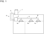
- Fig. 1 schematically illustrates an example of the installation of an air-conditioning apparatus according to Embodiment 1.
- the air-conditioning apparatus includes a heat source side refrigerant cycle circuit A through which heat source side refrigerant circulates, and a heat medium cycle circuit B through which a heat medium circulates to receive, transfer, or deliver heat.
- the air-conditioning apparatus conditions air in a room that is an air-conditioning target space by cooling or heating the air.
- the heat source side refrigerant cycle circuit A serves as a heat source side device that heats or cools a heat medium in the heat medium cycle circuit B to supply heating energy or cooling energy to the indoor side.
- the air-conditioning apparatus has one outdoor unit 1 serving as a heat source device, a plurality of indoor units 3 (indoor units 3a to 3c) serving as an indoor device, and a relay unit 2.
- the relay unit 2 is configured to relay heat transfer between heat source side refrigerant circulating through the heat source side refrigerant cycle circuit A and a heat medium circulating through the heat medium cycle circuit B.
- the outdoor unit 1 and the relay unit 2 are connected by a refrigerant pipe 5 serving as a flow passage for the heat source side refrigerant. It is also possible to connect a plurality of relay units 2 in parallel to one outdoor unit 1.
- Each of the indoor units 3 is connected to the relay unit 2 by a heat medium pipe 6 serving as a flow passage for the heat medium.
- the indoor units 3 are configured to condition indoor air that is a target to be air-conditioned.
- the indoor units 3 are an example of the destination to which heat is delivered through the heat medium.
- the indoor units 3 may be used to cool the devices for factory use, or may be used for reheating in a building.
- Examples of the heat source side refrigerant to be used, which circulates through the heat source side refrigerant cycle circuit A, include a single refrigerant such as R-22 or R-134a, a near-azeotropic refrigerant mixture such as R-410A or R-404A, and a non-azeotropic refrigerant mixture such as R-407C.
- a refrigerant which does not involve a phase change within its service temperature range, can be used such as brine (antifreeze), water, a liquid mixture of brine and water, or a liquid mixture of water and a highly anticorrosive additive.
- the air-conditioning apparatus in Embodiment 1 can use a very safe refrigerant as a heat medium.
- Fig. 2 illustrates an example of the configuration of the air-conditioning apparatus according to Embodiment 1.
- the configuration of devices included in the air-conditioning apparatus is described with reference to Fig. 2 .
- the outdoor unit 1 and the relay unit 2 are connected by the refrigerant pipe 5.
- the relay unit 2 is connected to each of the indoor units 3 by the heat medium pipe 6.
- three indoor units 3 (the indoor units 3a to 3c) are connected to the relay unit 2 through the heat medium pipe 6.
- the number of indoor units 3 to be connected to the relay unit 2 is not limited to three.
- the outdoor unit 1 is configured to cause heat source side refrigerant to circulate through the heat source side refrigerant cycle circuit A to deliver heat, and allow the heat source side refrigerant to exchange heat with a heat medium in a heat medium heat exchanger 20 in the relay unit 2.
- heat is delivered by the heat source side refrigerant.
- the outdoor unit 1 has a compressor 10, a flow switching valve 11, a heat source side heat exchanger 12, an accumulator 13, and a heat source side fan 14 in a housing.
- the compressor 10, the flow switching valve 11, the heat source side heat exchanger 12, and the accumulator 13 are connected by pipes and installed in the housing.
- the compressor 10 suctions the heat source side refrigerant, compresses the suctioned refrigerant into a high-temperature high-pressure state, and discharges the compressed refrigerant. It is preferable that the compressor 10 is constituted by, for example, a capacity controllable compressor.
- the flow switching valve 11 is a device to switch between flow passages for the heat source side refrigerant depending on cooling operation mode or heating operation mode. In a case where the air-conditioning apparatus only performs either cooling operation or heating operation, it is unnecessary to install the flow switching valve 11.
- the heat source side heat exchanger 12 allows the heat source side refrigerant to exchange heat with, for example, outdoor air supplied from the heat source side fan 14.
- the heat source side heat exchanger 12 serves as an evaporator in the heating operation mode to cause the heat source side refrigerant to receive heat.
- the heat source side heat exchanger 12 serves as a condenser or a radiator in the cooling operation mode to cause the heat source side refrigerant to transfer heat.
- the heat source side heat exchanger 12 also causes the heat source side refrigerant to transfer heat.
- the accumulator 13 is provided on the heat source side refrigerant suction side of the compressor 10.
- the accumulator 13 reserves surplus refrigerant generated due to a difference in heat source side circulating refrigerant amount to be used between the heating operation mode and the cooling operation mode, or generated during a transition period from one operation mode to another.
- the accumulator 13 may not be installed in the heat source side refrigerant cycle circuit A.
- the indoor unit 3 is configured to send the conditioned air to an indoor space.
- Each of the indoor units 3 in Embodiment 1 has an indoor heat exchanger 30 (indoor heat exchangers 30a to 30c).
- the indoor heat exchanger 30 is a constituent device of the heat medium cycle circuit B.
- the indoor heat exchanger 30 has, for example, heat transfer tubes and fins. A heat medium passes through the inside of the heat transfer tubes in the indoor heat exchanger 30.
- the indoor heat exchanger 30 allows a heat medium to exchange heat with room air supplied from an indoor side fan 31. When the heat medium that is cooler than the room air passes through the inside of the heat transfer tubes, the air is cooled and the indoor space is accordingly cooled.
- the indoor side fan 31 (indoor side fans 31a to 31c) helps air in the indoor space to pass through the indoor heat exchanger 30 and generates a flow of air that returns to the indoor space.
- the indoor unit 3 may have an indoor flow-rate regulation device configured to control the flow rate of a heat medium that flows into, and flows out from, the indoor heat exchanger 30.
- the relay unit 2 has devices associated with heat transfer between heat source side refrigerant that circulates through the heat source side refrigerant cycle circuit A and a heat medium that circulates through the heat medium cycle circuit B.
- the relay unit 2 has the heat medium heat exchanger 20, a pump 21, an expansion device 22, a bypass valve 23, a bypass pipe 24, a heat medium heat exchanger side pipe 25, a unit pipe 27, and a merging portion 26.
- the heat medium heat exchanger 20 allows the heat source side refrigerant and the heat medium to exchange heat between them to transfer heat from the heat source side refrigerant to the heat medium.
- the heat medium heat exchanger 20 serves as a condenser or a radiator to cause the heat source side refrigerant to transfer heat to the heat medium.
- the heat medium heat exchanger 20 serves as an evaporator to cause the heat source side refrigerant to receive heat from the heat medium.
- the pump 21 is a device configured to suction and pressurize the heat medium to cause this pressurized heat medium to circulate through the heat medium cycle circuit B.
- the expansion device 22 serves as a pressure reducing valve or an expansion valve, and is configured to reduce the pressure of the heat source side refrigerant and expand the heat source side refrigerant.
- the expansion device 22 is an electronic expansion valve that can control the opening degree to any degree and optionally regulate the flow rate of the heat source side refrigerant and other conditions.
- the bypass pipe 24 allows the heat source side refrigerant to bypass the heat medium heat exchanger 20.
- the air-conditioning apparatus in Embodiment 1 causes the heat source side refrigerant to pass through the bypass pipe 24 particularly during defrosting operation, and prevents the heat source side refrigerant from passing through the heat medium heat exchanger 20.
- the bypass valve 23 is installed in the bypass pipe 24.
- the bypass valve 23 allows the heat source side refrigerant to pass through the bypass pipe 24 or blocks the heat source side refrigerant from passing through the bypass pipe 24.
- the bypass valve 23 is an open-close valve such as a solenoid valve.
- the bypass valve 23 allows the heat source side refrigerant to pass through the bypass pipe 24 or blocks the heat source side refrigerant from passing through the bypass pipe 24 based on an instruction from the controller 4.
- a plurality of pipes are merged together.
- the merging portion 26 in Embodiment 1 has, for example, a T-shaped pipe serving as a connection pipe.
- the bypass pipe 24, the heat medium heat exchanger side pipe 25, and the unit pipe 27 are connected to the connection pipe.
- the connection pipe of the merging portion 26 may be a Y-shaped pipe.
- the heat medium heat exchanger side pipe 25 is one of the pipes to be connected to the merging portion 26, and has one end connected to the heat medium heat exchanger 20.
- the unit pipe 27 is one of the pipes to be connected to the merging portion 26, and has one end connected to the refrigerant pipe 5 extending outside the relay unit 2.
- the unit pipe 27 serves as a compressor side pipe that is indirectly connected to the compressor 10 in the outdoor unit 1.
- the unit pipe 27 is connected to the heat source side refrigerant suction side of the compressor 10.
- the heat source side refrigerant passes through the unit pipe 27 from the merging portion 26, and flows out from the relay unit 2.
- the heat source side heat exchanger 12 allows the heat source side refrigerant to exchange heat with air supplied by the heat source side fan 14 to condense and liquify the heat source side refrigerant.
- the heat source side refrigerant condensed and liquified in the heat source side heat exchanger 12 flows out from the outdoor unit 1, passes through the refrigerant pipe 5, flows into the relay unit 2, and passes through the expansion device 22.
- the expansion device 22 reduces the pressure of the condensed and liquified heat source side refrigerant passing through the expansion device 22.
- the heat source side refrigerant with its pressure reduced flows into the heat medium heat exchanger 20.
- the heat medium heat exchanger 20 allows the heat source side refrigerant passing therethrough to exchange heat with a heat medium to evaporate and gasify the heat source side refrigerant. At this time, the heat medium is cooled.
- the heat source side refrigerant having flowed out from the heat medium heat exchanger 20 flows out from the relay unit 2, passes through the refrigerant pipe 5, and flows into the outdoor unit 1.
- the heat source side refrigerant passes through the flow switching valve 11 again, further passes through the accumulator 13, and is then suctioned into the compressor 10.
- the compressor 10 suctions the heat source side refrigerant, compresses the suctioned refrigerant into a high-temperature high-pressure state, and discharges the compressed refrigerant.
- the heat source side refrigerant discharged from the compressor 10 flows out from the outdoor unit 1 through the flow switching valve 11, passes through the refrigerant pipe 5, and flows into the heat medium heat exchanger 20 in the relay unit 2.
- the heat medium heat exchanger 20 allows the heat source side refrigerant passing therethrough to exchange heat with a heat medium to condense and liquify the heat source side refrigerant. At this time, the heat medium is heated.
- the heat source side refrigerant having flowed out from the heat medium heat exchanger 20 passes through the expansion device 22.
- the expansion device 22 reduces the pressure of the condensed and liquified heat source side refrigerant passing through the expansion device 22.
- the heat source side refrigerant with its pressure reduced flows out from the relay unit 2, passes through the refrigerant pipe 5, flows into the outdoor unit 1, and then flows into the heat source side heat exchanger 12.
- the heat source side heat exchanger 12 allows the heat source side refrigerant to exchange heat with air supplied by the heat source side fan 14 to evaporate and gasify the heat source side refrigerant.
- the heat source side refrigerant passes through the flow switching valve 11 again, further passes through the accumulator 13, and is then suctioned into the compressor 10.
- the air-conditioning apparatus performs defrosting operation.
- the heat source side fan 14 stops driving.
- the expansion device 22 is brought into a closed state, while the bypass valve 23 is brought into an open state.
- the compressor 10 suctions heat source side refrigerant, compresses the refrigerant into a high-temperature high-pressure state, and discharges the compressed refrigerant.
- the heat source side refrigerant discharged from the compressor 10 flows into the heat source side heat exchanger 12 through the flow switching valve 11.
- the heat source side heat exchanger 12 allows the heat source side refrigerant to exchange heat with the frost formed on the heat source side heat exchanger 12.
- the heat source side refrigerant exchanges heat with the frost and thus condenses into a liquid state or a two-phase gas-liquid state.
- the heat source side refrigerant flows out from the outdoor unit 1, passes through the refrigerant pipe 5, and flows into the relay unit 2.
- the expansion device 22 is brought into a closed state, while the bypass valve 23 is brought into an open state.
- the heat source side refrigerant having flowed into the relay unit 2 passes through the bypass pipe 24, the bypass valve 23, and the merging portion 26, and then flows out from the relay unit 2.
- the heat source side refrigerant having flowed out from the relay unit 2 passes through the refrigerant pipe 5, and flows into the outdoor unit 1.
- the heat source side refrigerant in gas form is suctioned into the compressor 10.
- Fig. 3 illustrates an example of the configuration of the controller 4 included in the air-conditioning apparatus according to Embodiment 1.
- the controller 4 performs processing related to the air-conditioning apparatus based on the data on physical quantities included in signals transmitted from various types of sensors, and based on signals such as instructions and settings transmitted from an input device (not illustrated) or other devices.
- the controller 4 includes a defrosting determination unit 40, a device control unit 41, and a storage unit 42.
- the defrosting determination unit 40 determines whether the air-conditioning apparatus performs the defrosting operation based on a temperature of the heat source side refrigerant in the heat source side heat exchanger 12 detected by a heat source side heat exchanger temperature sensor 15 for the heat source side heat exchanger 12 in the outdoor unit 1, and based on a set temperature that is set in advance.
- the set temperature is a threshold that is set in advance for a temperature of the heat source side refrigerant at the outlet to determine whether the defrosting operation is necessary, and that is stored in the storage unit 42 as data.
- the device control unit 41 controls the outdoor unit 1, the relay unit 2, and the indoor units 3a to 3c based on the results of the processing performed by each unit of the controller 4. Particularly, in Embodiment 1, the device control unit 41 controls the outdoor unit 1 and the relay unit 2 when the air-conditioning apparatus performs the defrosting operation.
- the storage unit 42 stores therein various kinds of data to be used when the controller 4 performs the processing.
- Fig. 4 illustrates an example of the arrangement structure of pipes through which heat source side refrigerant passes in the relay unit 2 according to Embodiment 1. Arrangement of the pipes at and around the merging portion 26 is now described.
- the arrows in Fig. 4 show a flow of the heat source side refrigerant during the defrosting operation.
- liquid-phase or two-phase gas-liquid heat source side refrigerant passes through the relay unit 2.
- the expansion device 22 is brought into a closed state, while the bypass valve 23 is brought into an open state.
- the heat source side refrigerant passes through the merging portion 26a of the heat medium heat exchanger side pipe 25 and the bypass pipe 24, and returns to the outdoor unit 1.
- the positional relationship between pipes to be connected to the merging portion 26a in the relay unit 2 is illustrated in Fig. 4 .
- the bypass pipe 24 connects to the merging portion 26a with its pipe axis oriented in the horizontal direction.
- the unit pipe 27 connects to the merging portion 26a with its pipe axis oriented in a vertical direction (gravity direction) from the lower side (hereinafter, referred to as "oriented in the vertically downward direction").
- the heat medium heat exchanger side pipe 25 connects to the merging portion 26a with its pipe axis oriented in the vertical direction from the upper side (hereinafter, referred to as "oriented in the vertically upward direction").
- Fig. 4 illustrates an example of the connection of the merging portion 26a and each of the pipes.
- each of the pipes is connected to the merging portion 26a horizontally or vertically, the pipes are not necessarily connected to each other with a 90-degree angle relationship between them. It suffices that the pipes are connected to each other at such an angle as to prevent liquid-phase heat source side refrigerant from flowing into the heat medium heat exchanger 20 through the heat medium heat exchanger side pipe 25.
- Fig. 5 is an explanatory view illustrating an example of the structure of the merging portion 26a according to Embodiment 1.
- the merging portion 26a as illustrated in Fig. 5 has such a structure that the pipe extending in the vertical direction has an increased pipe diameter. Therefore, in the connection pipe of the merging portion 26a, a pipe connecting to the unit pipe 27 and to the heat medium heat exchanger side pipe 25 has a larger cross-sectional area than the cross-sectional area of a pipe connecting to the bypass pipe 24.
- Fig. 6 is an explanatory view illustrating another example of the structure of the merging portion 26a according to Embodiment 1.
- the merging portion 26a has such a structure as to serve as a gas-liquid separation device.
- the merging portion 26a illustrated in Fig. 6 serves as a cyclone gas-liquid separator to separate the heat source side refrigerant into gas-phase refrigerant and liquid-phase refrigerant.
- the gas-phase heat source side refrigerant flows in the upward direction, while the liquid-phase heat source side refrigerant flows in the downward direction (gravity direction).
- the bypass pipe 24, the heat medium heat exchanger side pipe 25, and the unit pipe 27 are connected to the merging portion 26a.
- the heat medium heat exchanger side pipe 25 connects to the merging portion 26 with its pipe axis oriented upward relative to the horizontal direction when viewed from the merging portion 26.
- the heat medium heat exchanger side pipe 25 connects to the merging portion 26a with its pipe axis oriented in the vertically upward direction.
- liquid-phase heat source side refrigerant flowing into the merging portion 26a is prevented from flowing back through the heat medium heat exchanger side pipe 25 and flowing into the heat medium heat exchanger 20.
- This structure prevents low-temperature liquid-phase heat source side refrigerant from flowing into the heat medium heat exchanger 20, prevents the heat medium from freezing in the heat medium heat exchanger 20, and can consequently prevent the occurrence of freezing puncture.
- Fig. 7 illustrates a modification of the arrangement structure of the pipes through which heat source side refrigerant passes in the relay unit 2 according to Embodiment 1.
- the positional relationship between pipes to be connected to a merging portion 26b in the relay unit 2 is illustrated in Fig. 7 .
- the bypass pipe 24 connects to the merging portion 26b with its pipe axis oriented in the vertically downward direction.
- the unit pipe 27 connects to the merging portion 26b with its pipe axis oriented in the horizontal direction.
- the heat medium heat exchanger side pipe 25 connects to the merging portion 26b with its pipe axis oriented in the vertically upward direction.
- Fig. 7 illustrates an example of the connection of the merging portion 26b and each of the pipes.
- each of the pipes is connected to the merging portion 26b horizontally or vertically, the pipes are not necessarily connected to each other with a 90-degree angle relationship between them. It suffices that the pipes are connected to each other at such an angle as to prevent liquid-phase heat source side refrigerant from flowing into the heat medium heat exchanger 20 through the heat medium heat exchanger side pipe 25.
- Fig. 8 illustrates another modification of the arrangement structure of the pipes through which heat source side refrigerant passes in the relay unit 2 according to Embodiment 1.
- the positional relationship between pipes to be connected to a merging portion 26c in the relay unit 2 is illustrated in Fig. 8 .
- the bypass pipe 24 connects to the merging portion 26c with its pipe axis oriented in the horizontal direction.
- the unit pipe 27 connects to the merging portion 26c with its pipe axis oriented in the horizontal direction.
- the heat medium heat exchanger side pipe 25 connects to the merging portion 26c with its pipe axis oriented in the vertically upward direction. Therefore, the bypass pipe 24 and the unit pipe 27 have a straight pipe connection relationship between them.
- each of the pipes is connected to the merging portion 26c horizontally or vertically
- the pipes are not necessarily connected to each other with a 90-degree angle relationship between them. It suffices that the pipes are connected to each other at such an angle as to prevent liquid-phase heat source side refrigerant from flowing into the heat medium heat exchanger 20 through the heat medium heat exchanger side pipe 25.
- Fig. 9 illustrates still another modification of the arrangement structure of the pipes through which heat source side refrigerant passes in the relay unit 2 according to Embodiment 1.
- the positional relationship between pipes to be connected to a merging portion 26d in the relay unit 2 is illustrated in Fig. 9 .
- the bypass pipe 24 connects to the merging portion 26d with its pipe axis oriented in the vertically downward direction.
- the unit pipe 27 connects to the merging portion 26d with its pipe axis oriented in the horizontal direction.
- the heat medium heat exchanger side pipe 25 connects to the merging portion 26d with its pipe axis inclined toward the upward direction relative to the merging portion 26d in the horizontal direction.
- the heat medium heat exchanger side pipe 25 is located in an L-shape in such a manner that the pipe connects to the merging portion 26d in the horizontal direction and is inclined at an angle of 90 degrees to be oriented in the vertically upward direction.
- Fig. 9 illustrates an example of the connection of the merging portion 26d and each of the pipes.
- the pipes are not necessarily connected to each other with a 90-degree angle relationship between them. It suffices that the pipes are connected to each other at such an angle as to prevent liquid-phase heat source side refrigerant from flowing into the heat medium heat exchanger 20 through the heat medium heat exchanger side pipe 25.
- Fig. 10 illustrates the configuration of the air-conditioning apparatus according to Embodiment 2.
- devices denoted by the same reference signs as those in Fig. 2 operate in the same manner as in Embodiment 1.
- the air-conditioning apparatus in Embodiment 2 has a refrigerant flow switching device 28 at a location of the merging portion 26 in the relay unit 2 which has been explained in Embodiment 1.
- the refrigerant flow switching device 28 has, for example, a three-way valve.
- the refrigerant flow switching device 28 switches between the flow passages, thereby to allow the bypass pipe 24 or the heat medium heat exchanger side pipe 25 to communicate with the unit pipe 27 to switch between the flow directions of heat source side refrigerant.
- the refrigerant flow switching device 28 switches the flow passage to such a flow passage that the heat medium heat exchanger 20 communicates with the outdoor unit 1.
- the refrigerant flow switching device 28 switches the flow passage to such a flow passage that the bypass pipe 24 communicates with the unit pipe 27.
- the controller 4 controls switching between the flow passages in the refrigerant flow switching device 28.
- the air-conditioning apparatus in Embodiment 2 has the refrigerant flow switching device 28, so that in the defrosting operation, the refrigerant flow switching device 28 switches the flow passage to such a flow passage as to allow the bypass valve 23 to communicate with the heat medium heat exchanger side pipe 25, and block the bypass valve 23 from communicating with the heat medium heat exchanger side pipe 25.
- the refrigerant flow switching device 28 switches the flow passage to such a flow passage as to allow the bypass valve 23 to communicate with the heat medium heat exchanger side pipe 25, and block the bypass valve 23 from communicating with the heat medium heat exchanger side pipe 25.
- Fig. 11 illustrates the configuration of the air-conditioning apparatus according to Embodiment 3.
- devices denoted by the same reference signs as those in Fig. 1 and other drawings operate in the same manner as in Embodiment 1 or 2.
- the air-conditioning apparatus in Embodiment 3 has a plurality of the relay units 2 described in Embodiment 1 or 2.
- the air-conditioning apparatus is supposed to have two relay units 2 including a relay unit 2a and a relay unit 2b.
- the two relay units 2 are connected by the refrigerant pipe 5 in parallel to the outdoor unit 1, forming the heat source side refrigerant cycle circuit A.
- the relay unit 2a is connected to the indoor units 3a to 3c by the heat medium pipe 6, forming the heat medium cycle circuit B.
- the relay unit 2b is connected to indoor units 3d to 3f by the heat medium pipe 6, forming the heat medium cycle circuit B.
- Fig. 12 illustrates the configuration of the air-conditioning apparatus according to Embodiment 4.
- devices denoted by the same reference signs as those in Fig. 1 and other drawings operate in the same manner as in Embodiment 1 or 2.
- the indoor unit 3a and the relay unit 2 are connected in parallel to the outdoor unit 1 described in Embodiment 1 or 2 by the refrigerant pipe 5, forming the heat source side refrigerant cycle circuit A. Therefore, the indoor unit 3a in Embodiment 4 allows heat source side refrigerant to exchange heat with air in an indoor space. As described in Embodiment 4, even in the air-conditioning apparatus having the indoor unit 3 in the heat source side refrigerant cycle circuit A, it is still possible to connect the pipes in the relay unit 2 as described in Embodiment 1 or 2.
- heat source side refrigerant resulting from defrosting is prevented from flowing into the heat medium heat exchanger 20 through the heat medium heat exchanger side pipe 25. This can prevent stagnation of the heat source side refrigerant and prevent the occurrence of freezing puncture due to freezing of the heat medium.
- Fig. 13 illustrates the configuration of the air-conditioning apparatus according to Embodiment 5.
- devices denoted by the same reference signs as those in Fig. 2 and other drawings operate in the same manner as in Embodiment 1.
- the air-conditioning apparatus in Embodiment 5 has a configuration in which the devices in the relay unit 2 described in Embodiment 1 are integrated into the outdoor unit 1. With this configuration, in the air-conditioning apparatus in Embodiment 5, the outdoor unit 1 is connected to each of the indoor units 3 by the heat medium pipe 6.
Landscapes
- Engineering & Computer Science (AREA)
- Physics & Mathematics (AREA)
- Mechanical Engineering (AREA)
- Thermal Sciences (AREA)
- General Engineering & Computer Science (AREA)
- Fluid Mechanics (AREA)
- Compression-Type Refrigeration Machines With Reversible Cycles (AREA)
Abstract
Description
- The present disclosure relates to an air-conditioning apparatus. The present disclosure particularly relates to freeze protection for a heat medium in a heat medium heat exchanger.
- There is an air-conditioning apparatus in which a heat medium cycle circuit is formed between a heat source side device and an indoor unit to cause a heat medium including water, brine, or other refrigerant to circulate through the heat medium cycle circuit to condition air. In this air-conditioning apparatus, the heat source side device has a heat source side refrigerant cycle circuit through which heat source side refrigerant circulates and exchanges heat with the heat medium in a heat medium heat exchanger to heat or cool the heat medium, thereby to supply heat to the indoor unit. The indoor unit uses the heat supplied through the heat medium to heat or cool the air in a room to condition the air (see, for example, Patent Literature 1).
- Patent Literature 1:
Japanese Unexamined Patent Application Publication No. 2017-053507 - The air-conditioning apparatus sometimes performs defrosting operation to defrost the heat source side heat exchanger in the heat source side refrigerant cycle circuit by causing high-temperature heat source side refrigerant to pass through the heat source side heat exchanger. At this time, in the heat source side refrigerant cycle circuit, an expansion device is brought into an open state through which the heat source side refrigerant flows into the heat medium heat exchanger. The heat source side refrigerant having exchanged heat with the frost becomes liquid-phase or two-phase gas-liquid low-temperature refrigerant. In view of that, the heat source side refrigerant having flowed into the heat medium heat exchanger may freeze the heat medium in the heat medium heat exchanger. When the heat medium becomes frozen, freezing puncture occurs due to volume expansion of the heat medium, which may break or deform heat transfer tubes of the heat medium heat exchanger.
- Thus, an air-conditioning apparatus is also conceivable in which a heat source side refrigerant cycle circuit has a bypass pipe through which low-temperature heat source side refrigerant can pass. However, even though the expansion device is brought into a closed state to allow the heat source side refrigerant to pass through the bypass pipe, liquid-phase heat source side refrigerant having passed through the bypass pipe may still flow back into the heat medium heat exchanger.
- It is therefore an object of the present disclosure to provide an air-conditioning apparatus having a structure designed to prevent low-temperature heat source side refrigerant from flowing into a heat medium heat exchanger.
- An air-conditioning apparatus according to an embodiment of the present disclosure includes: a heat medium cycle circuit in which a pump configured to pressurize a heat medium and an indoor heat exchanger configured to allow the heat medium to exchange heat with indoor air are connected by pipes to cause the heat medium to circulate through the heat medium cycle circuit, the heat medium serving as a heat delivery medium, the indoor air being a target to be air-conditioned; and a heat source side refrigerant cycle circuit in which a compressor, a heat source side heat exchanger, an expansion device, and a heat medium heat exchanger are connected by pipes to cause heat source side refrigerant to circulate through the heat source side refrigerant cycle circuit, the compressor being configured to compress the heat source side refrigerant, the heat source side heat exchanger being configured to allow the heat source side refrigerant to exchange heat with outdoor air, the expansion device being configured to reduce a pressure of the heat source side refrigerant, the heat medium heat exchanger being configured to allow the heat source side refrigerant to exchange heat with the heat medium, wherein the heat source side refrigerant cycle circuit has a bypass pipe through which the heat source side refrigerant passes to bypass the heat medium heat exchanger, a bypass valve configured to allow the heat source side refrigerant to pass through the bypass pipe or block the heat source side refrigerant from passing through the bypass pipe, and a merging portion to which a heat medium heat exchanger side pipe, a compressor side pipe, and the bypass pipe are connected, the heat medium heat exchanger side pipe having one end connected to the heat medium heat exchanger, the compressor side pipe having one end connected to a heat source side refrigerant suction side of the compressor, and the heat medium heat exchanger side pipe in the merging portion is connected to the compressor side pipe and the bypass pipe with a pipe axis thereof being upwardly inclined relative to a horizontal direction or being oriented upward in a vertical direction when viewed from the merging portion.
- In the air-conditioning apparatus according to an embodiment of the present disclosure, at the merging portion to which a plurality of pipes are connected, the heat medium heat exchanger side pipe is connected to the compressor side pipe and the bypass pipe with a pipe axis thereof being upwardly inclined relative to a horizontal direction or being oriented upward in a vertical direction. This structure prevents low-temperature liquid-phase heat source side refrigerant that enters the merging portion from flowing into the heat medium heat exchanger through the heat medium heat exchanger side pipe, prevents the heat medium from freezing in the heat medium heat exchanger, and can consequently prevent the occurrence of freezing puncture.
-
- [
Fig. 1] Fig. 1 schematically illustrates an example of the installation of an air-conditioning apparatus according toEmbodiment 1. - [
Fig. 2] Fig. 2 illustrates an example of the configuration of the air-conditioning apparatus according toEmbodiment 1. - [
Fig. 3] Fig. 3 illustrates an example of the configuration of acontroller 4 included in the air-conditioning apparatus according toEmbodiment 1. - [
Fig. 4] Fig. 4 illustrates an example of the arrangement structure of pipes through which heat source side refrigerant passes in arelay unit 2 according toEmbodiment 1. - [
Fig. 5] Fig. 5 is an explanatory view illustrating an example of the structure of a mergingportion 26a according toEmbodiment 1. - [
Fig. 6] Fig. 6 is an explanatory view illustrating another example of the structure of the mergingportion 26a according toEmbodiment 1. - [
Fig. 7] Fig. 7 illustrates a modification of the arrangement structure of the pipes through which heat source side refrigerant passes in therelay unit 2 according toEmbodiment 1. - [
Fig. 8] Fig. 8 illustrates another modification of the arrangement structure of the pipes through which heat source side refrigerant passes in therelay unit 2 according toEmbodiment 1. - [
Fig. 9] Fig. 9 illustrates still another modification of the arrangement structure of the pipes through which heat source side refrigerant passes in therelay unit 2 according toEmbodiment 1. - [
Fig. 10] Fig. 10 illustrates the configuration of the air-conditioning apparatus according toEmbodiment 2. - [
Fig. 11] Fig. 11 illustrates the configuration of the air-conditioning apparatus according to Embodiment 3. - [
Fig. 12] Fig. 12 illustrates the configuration of the air-conditioning apparatus according toEmbodiment 4. - [
Fig. 13] Fig. 13 illustrates the configuration of the air-conditioning apparatus according toEmbodiment 5. - An air-conditioning apparatus according to an embodiment will be described below with reference to the drawings and the like. In the drawings below, like reference signs denote similar or corresponding components, and are common throughout the entire descriptions of the embodiments described below. In addition, the relationship of sizes of the components in the drawings may differ from that of actual ones. Furthermore, in a part of the cross-sectional views, hatching of the device is omitted in light of visibility. The forms of the constituent elements described throughout the entire specification are merely examples, and do not intend to limit the constituent elements to the forms described in the specification. In particular, the combination of constituent elements is not limited to only the combination in each embodiment, and the constituent elements described in one embodiment can be applied to another embodiment. In the drawings, the upper side is described as "top," while the lower side is described as "bottom." Furthermore, the level of the pressure and temperature is not particularly determined in relation to an absolute value, but is determined relative to the conditions and operation of the device and the like. In addition, when there is no particular need to distinguish or identify a plurality of devices of the same type that are distinguished usually by subscripts, the subscripts may be omitted. The relationship of sizes of the components in the drawings may differ from that of actual ones.
-
Fig. 1 schematically illustrates an example of the installation of an air-conditioning apparatus according toEmbodiment 1. An example of the installation of the air-conditioning apparatus according toEmbodiment 1 is described with reference toFig. 1 . The air-conditioning apparatus includes a heat source side refrigerant cycle circuit A through which heat source side refrigerant circulates, and a heat medium cycle circuit B through which a heat medium circulates to receive, transfer, or deliver heat. The air-conditioning apparatus conditions air in a room that is an air-conditioning target space by cooling or heating the air. The heat source side refrigerant cycle circuit A serves as a heat source side device that heats or cools a heat medium in the heat medium cycle circuit B to supply heating energy or cooling energy to the indoor side. - In
Fig. 1 , the air-conditioning apparatus according to Embodiment 1 has oneoutdoor unit 1 serving as a heat source device, a plurality of indoor units 3 (indoor units 3a to 3c) serving as an indoor device, and arelay unit 2. Therelay unit 2 is configured to relay heat transfer between heat source side refrigerant circulating through the heat source side refrigerant cycle circuit A and a heat medium circulating through the heat medium cycle circuit B. Theoutdoor unit 1 and therelay unit 2 are connected by arefrigerant pipe 5 serving as a flow passage for the heat source side refrigerant. It is also possible to connect a plurality ofrelay units 2 in parallel to oneoutdoor unit 1. - Each of the indoor units 3 is connected to the
relay unit 2 by aheat medium pipe 6 serving as a flow passage for the heat medium. The indoor units 3 are configured to condition indoor air that is a target to be air-conditioned. The indoor units 3 are an example of the destination to which heat is delivered through the heat medium. Other than that, the indoor units 3 may be used to cool the devices for factory use, or may be used for reheating in a building. - Examples of the heat source side refrigerant to be used, which circulates through the heat source side refrigerant cycle circuit A, include a single refrigerant such as R-22 or R-134a, a near-azeotropic refrigerant mixture such as R-410A or R-404A, and a non-azeotropic refrigerant mixture such as R-407C. A relatively-low global warming potential refrigerant containing a double bond in its chemical formula, such as CF3CF=CH2, a mixture containing the relatively-low global warming potential refrigerant, and a natural refrigerant such as CO2 or propane can also be used.
- For example, as a heat medium that circulates through the heat medium cycle circuit B, a refrigerant, which does not involve a phase change within its service temperature range, can be used such as brine (antifreeze), water, a liquid mixture of brine and water, or a liquid mixture of water and a highly anticorrosive additive. As described above, the air-conditioning apparatus in
Embodiment 1 can use a very safe refrigerant as a heat medium. -
Fig. 2 illustrates an example of the configuration of the air-conditioning apparatus according toEmbodiment 1. The configuration of devices included in the air-conditioning apparatus is described with reference toFig. 2 . As described above, theoutdoor unit 1 and therelay unit 2 are connected by therefrigerant pipe 5. Therelay unit 2 is connected to each of the indoor units 3 by theheat medium pipe 6. InFig. 2 , three indoor units 3 (theindoor units 3a to 3c) are connected to therelay unit 2 through theheat medium pipe 6. However, the number of indoor units 3 to be connected to therelay unit 2 is not limited to three. - The
outdoor unit 1 is configured to cause heat source side refrigerant to circulate through the heat source side refrigerant cycle circuit A to deliver heat, and allow the heat source side refrigerant to exchange heat with a heat medium in a heatmedium heat exchanger 20 in therelay unit 2. InEmbodiment 1, in theoutdoor unit 1, heat is delivered by the heat source side refrigerant. Theoutdoor unit 1 has acompressor 10, aflow switching valve 11, a heat sourceside heat exchanger 12, anaccumulator 13, and a heatsource side fan 14 in a housing. Thecompressor 10, theflow switching valve 11, the heat sourceside heat exchanger 12, and theaccumulator 13 are connected by pipes and installed in the housing. Thecompressor 10 suctions the heat source side refrigerant, compresses the suctioned refrigerant into a high-temperature high-pressure state, and discharges the compressed refrigerant. It is preferable that thecompressor 10 is constituted by, for example, a capacity controllable compressor. Theflow switching valve 11 is a device to switch between flow passages for the heat source side refrigerant depending on cooling operation mode or heating operation mode. In a case where the air-conditioning apparatus only performs either cooling operation or heating operation, it is unnecessary to install theflow switching valve 11. - The heat source
side heat exchanger 12 allows the heat source side refrigerant to exchange heat with, for example, outdoor air supplied from the heatsource side fan 14. The heat sourceside heat exchanger 12 serves as an evaporator in the heating operation mode to cause the heat source side refrigerant to receive heat. The heat sourceside heat exchanger 12 serves as a condenser or a radiator in the cooling operation mode to cause the heat source side refrigerant to transfer heat. In defrosting operation to defrost the heat sourceside heat exchanger 12, the heat sourceside heat exchanger 12 also causes the heat source side refrigerant to transfer heat. Theaccumulator 13 is provided on the heat source side refrigerant suction side of thecompressor 10. For example, theaccumulator 13 reserves surplus refrigerant generated due to a difference in heat source side circulating refrigerant amount to be used between the heating operation mode and the cooling operation mode, or generated during a transition period from one operation mode to another. Theaccumulator 13 may not be installed in the heat source side refrigerant cycle circuit A. - The indoor unit 3 is configured to send the conditioned air to an indoor space. Each of the indoor units 3 in
Embodiment 1 has an indoor heat exchanger 30 (indoor heat exchangers 30a to 30c). The indoor heat exchanger 30 is a constituent device of the heat medium cycle circuit B. The indoor heat exchanger 30 has, for example, heat transfer tubes and fins. A heat medium passes through the inside of the heat transfer tubes in the indoor heat exchanger 30. The indoor heat exchanger 30 allows a heat medium to exchange heat with room air supplied from anindoor side fan 31. When the heat medium that is cooler than the room air passes through the inside of the heat transfer tubes, the air is cooled and the indoor space is accordingly cooled. When the heat medium that is warmer than the room air passes through the inside of the heat transfer tubes, the air is heated and the indoor space is accordingly heated. The indoor side fan 31 (indoor side fans 31a to 31c) helps air in the indoor space to pass through the indoor heat exchanger 30 and generates a flow of air that returns to the indoor space. The indoor unit 3 may have an indoor flow-rate regulation device configured to control the flow rate of a heat medium that flows into, and flows out from, the indoor heat exchanger 30. - Next, the configuration of the
relay unit 2 is described. Therelay unit 2 has devices associated with heat transfer between heat source side refrigerant that circulates through the heat source side refrigerant cycle circuit A and a heat medium that circulates through the heat medium cycle circuit B. Therelay unit 2 has the heatmedium heat exchanger 20, apump 21, anexpansion device 22, abypass valve 23, abypass pipe 24, a heat medium heatexchanger side pipe 25, aunit pipe 27, and a mergingportion 26. - The heat
medium heat exchanger 20 allows the heat source side refrigerant and the heat medium to exchange heat between them to transfer heat from the heat source side refrigerant to the heat medium. When heating the heat medium, the heatmedium heat exchanger 20 serves as a condenser or a radiator to cause the heat source side refrigerant to transfer heat to the heat medium. When cooling the heat medium, the heatmedium heat exchanger 20 serves as an evaporator to cause the heat source side refrigerant to receive heat from the heat medium. Thepump 21 is a device configured to suction and pressurize the heat medium to cause this pressurized heat medium to circulate through the heat medium cycle circuit B. - The
expansion device 22 serves as a pressure reducing valve or an expansion valve, and is configured to reduce the pressure of the heat source side refrigerant and expand the heat source side refrigerant. For example, it is preferable that theexpansion device 22 is an electronic expansion valve that can control the opening degree to any degree and optionally regulate the flow rate of the heat source side refrigerant and other conditions. - The
bypass pipe 24 allows the heat source side refrigerant to bypass the heatmedium heat exchanger 20. The air-conditioning apparatus inEmbodiment 1 causes the heat source side refrigerant to pass through thebypass pipe 24 particularly during defrosting operation, and prevents the heat source side refrigerant from passing through the heatmedium heat exchanger 20. Thebypass valve 23 is installed in thebypass pipe 24. Thebypass valve 23 allows the heat source side refrigerant to pass through thebypass pipe 24 or blocks the heat source side refrigerant from passing through thebypass pipe 24. Thebypass valve 23 is an open-close valve such as a solenoid valve. As will be described later, thebypass valve 23 allows the heat source side refrigerant to pass through thebypass pipe 24 or blocks the heat source side refrigerant from passing through thebypass pipe 24 based on an instruction from thecontroller 4. At the mergingportion 26, a plurality of pipes are merged together. The mergingportion 26 inEmbodiment 1 has, for example, a T-shaped pipe serving as a connection pipe. Thebypass pipe 24, the heat medium heatexchanger side pipe 25, and theunit pipe 27 are connected to the connection pipe. The connection pipe of the mergingportion 26 may be a Y-shaped pipe. The heat medium heatexchanger side pipe 25 is one of the pipes to be connected to the mergingportion 26, and has one end connected to the heatmedium heat exchanger 20. Theunit pipe 27 is one of the pipes to be connected to the mergingportion 26, and has one end connected to therefrigerant pipe 5 extending outside therelay unit 2. In the heat source side refrigerant cycle circuit A, theunit pipe 27 serves as a compressor side pipe that is indirectly connected to thecompressor 10 in theoutdoor unit 1. For example, during cooling operation and defrosting operation, theunit pipe 27 is connected to the heat source side refrigerant suction side of thecompressor 10. The heat source side refrigerant passes through theunit pipe 27 from the mergingportion 26, and flows out from therelay unit 2. - Operation and the like of the constituent devices of the air-conditioning apparatus in the heat source side refrigerant cycle circuit A are now described based on a flow of the heat source side refrigerant that circulates through the heat source side refrigerant cycle circuit A. First, the operation to cool a heat medium is described. The
compressor 10 suctions heat source side refrigerant, compresses the refrigerant into a high-temperature high-pressure state, and discharges the compressed refrigerant. The heat source side refrigerant discharged from thecompressor 10 flows into the heat sourceside heat exchanger 12 through theflow switching valve 11. The heat sourceside heat exchanger 12 allows the heat source side refrigerant to exchange heat with air supplied by the heatsource side fan 14 to condense and liquify the heat source side refrigerant. The heat source side refrigerant condensed and liquified in the heat sourceside heat exchanger 12 flows out from theoutdoor unit 1, passes through therefrigerant pipe 5, flows into therelay unit 2, and passes through theexpansion device 22. Theexpansion device 22 reduces the pressure of the condensed and liquified heat source side refrigerant passing through theexpansion device 22. The heat source side refrigerant with its pressure reduced flows into the heatmedium heat exchanger 20. The heatmedium heat exchanger 20 allows the heat source side refrigerant passing therethrough to exchange heat with a heat medium to evaporate and gasify the heat source side refrigerant. At this time, the heat medium is cooled. The heat source side refrigerant having flowed out from the heatmedium heat exchanger 20 flows out from therelay unit 2, passes through therefrigerant pipe 5, and flows into theoutdoor unit 1. The heat source side refrigerant passes through theflow switching valve 11 again, further passes through theaccumulator 13, and is then suctioned into thecompressor 10. - Next, the operation to heat a heat medium is described. The
compressor 10 suctions the heat source side refrigerant, compresses the suctioned refrigerant into a high-temperature high-pressure state, and discharges the compressed refrigerant. The heat source side refrigerant discharged from thecompressor 10 flows out from theoutdoor unit 1 through theflow switching valve 11, passes through therefrigerant pipe 5, and flows into the heatmedium heat exchanger 20 in therelay unit 2. The heatmedium heat exchanger 20 allows the heat source side refrigerant passing therethrough to exchange heat with a heat medium to condense and liquify the heat source side refrigerant. At this time, the heat medium is heated. The heat source side refrigerant having flowed out from the heatmedium heat exchanger 20 passes through theexpansion device 22. Theexpansion device 22 reduces the pressure of the condensed and liquified heat source side refrigerant passing through theexpansion device 22. The heat source side refrigerant with its pressure reduced flows out from therelay unit 2, passes through therefrigerant pipe 5, flows into theoutdoor unit 1, and then flows into the heat sourceside heat exchanger 12. The heat sourceside heat exchanger 12 allows the heat source side refrigerant to exchange heat with air supplied by the heatsource side fan 14 to evaporate and gasify the heat source side refrigerant. The heat source side refrigerant passes through theflow switching valve 11 again, further passes through theaccumulator 13, and is then suctioned into thecompressor 10. - Furthermore, a case where the air-conditioning apparatus performs defrosting operation is described. When the air-conditioning apparatus performs the defrosting operation, the heat
source side fan 14 stops driving. Theexpansion device 22 is brought into a closed state, while thebypass valve 23 is brought into an open state. Thecompressor 10 suctions heat source side refrigerant, compresses the refrigerant into a high-temperature high-pressure state, and discharges the compressed refrigerant. The heat source side refrigerant discharged from thecompressor 10 flows into the heat sourceside heat exchanger 12 through theflow switching valve 11. The heat sourceside heat exchanger 12 allows the heat source side refrigerant to exchange heat with the frost formed on the heat sourceside heat exchanger 12. The heat source side refrigerant exchanges heat with the frost and thus condenses into a liquid state or a two-phase gas-liquid state. The heat source side refrigerant flows out from theoutdoor unit 1, passes through therefrigerant pipe 5, and flows into therelay unit 2. As described above, theexpansion device 22 is brought into a closed state, while thebypass valve 23 is brought into an open state. Thus, the heat source side refrigerant having flowed into therelay unit 2 passes through thebypass pipe 24, thebypass valve 23, and the mergingportion 26, and then flows out from therelay unit 2. The heat source side refrigerant having flowed out from therelay unit 2 passes through therefrigerant pipe 5, and flows into theoutdoor unit 1. The heat source side refrigerant in liquid form, contained in the heat source side refrigerant having flowed into theoutdoor unit 1, accumulates in theaccumulator 13. In contrast, the heat source side refrigerant in gas form is suctioned into thecompressor 10. -
Fig. 3 illustrates an example of the configuration of thecontroller 4 included in the air-conditioning apparatus according toEmbodiment 1. Thecontroller 4 performs processing related to the air-conditioning apparatus based on the data on physical quantities included in signals transmitted from various types of sensors, and based on signals such as instructions and settings transmitted from an input device (not illustrated) or other devices. Thecontroller 4 includes adefrosting determination unit 40, adevice control unit 41, and astorage unit 42. Thedefrosting determination unit 40 determines whether the air-conditioning apparatus performs the defrosting operation based on a temperature of the heat source side refrigerant in the heat sourceside heat exchanger 12 detected by a heat source side heatexchanger temperature sensor 15 for the heat sourceside heat exchanger 12 in theoutdoor unit 1, and based on a set temperature that is set in advance. The set temperature is a threshold that is set in advance for a temperature of the heat source side refrigerant at the outlet to determine whether the defrosting operation is necessary, and that is stored in thestorage unit 42 as data. Thedevice control unit 41 controls theoutdoor unit 1, therelay unit 2, and theindoor units 3a to 3c based on the results of the processing performed by each unit of thecontroller 4. Particularly, inEmbodiment 1, thedevice control unit 41 controls theoutdoor unit 1 and therelay unit 2 when the air-conditioning apparatus performs the defrosting operation. Thestorage unit 42 stores therein various kinds of data to be used when thecontroller 4 performs the processing. -
Fig. 4 illustrates an example of the arrangement structure of pipes through which heat source side refrigerant passes in therelay unit 2 according toEmbodiment 1. Arrangement of the pipes at and around the mergingportion 26 is now described. The arrows inFig. 4 show a flow of the heat source side refrigerant during the defrosting operation. During the defrosting operation, liquid-phase or two-phase gas-liquid heat source side refrigerant passes through therelay unit 2. During the defrosting operation, theexpansion device 22 is brought into a closed state, while thebypass valve 23 is brought into an open state. Via thebypass pipe 24, the heat source side refrigerant passes through the mergingportion 26a of the heat medium heatexchanger side pipe 25 and thebypass pipe 24, and returns to theoutdoor unit 1. - The positional relationship between pipes to be connected to the merging
portion 26a in therelay unit 2 is illustrated inFig. 4 . Thebypass pipe 24 connects to the mergingportion 26a with its pipe axis oriented in the horizontal direction. Theunit pipe 27 connects to the mergingportion 26a with its pipe axis oriented in a vertical direction (gravity direction) from the lower side (hereinafter, referred to as "oriented in the vertically downward direction"). Furthermore, the heat medium heatexchanger side pipe 25 connects to the mergingportion 26a with its pipe axis oriented in the vertical direction from the upper side (hereinafter, referred to as "oriented in the vertically upward direction").Fig. 4 illustrates an example of the connection of the mergingportion 26a and each of the pipes. In this example, while each of the pipes is connected to the mergingportion 26a horizontally or vertically, the pipes are not necessarily connected to each other with a 90-degree angle relationship between them. It suffices that the pipes are connected to each other at such an angle as to prevent liquid-phase heat source side refrigerant from flowing into the heatmedium heat exchanger 20 through the heat medium heatexchanger side pipe 25. -
Fig. 5 is an explanatory view illustrating an example of the structure of the mergingportion 26a according toEmbodiment 1. The mergingportion 26a as illustrated inFig. 5 has such a structure that the pipe extending in the vertical direction has an increased pipe diameter. Therefore, in the connection pipe of the mergingportion 26a, a pipe connecting to theunit pipe 27 and to the heat medium heatexchanger side pipe 25 has a larger cross-sectional area than the cross-sectional area of a pipe connecting to thebypass pipe 24. With this structure, during the period until the heat source side refrigerant having flowed into the mergingportion 26a from thebypass pipe 24 hits a pipe wall of the mergingportion 26a, liquid-phase heat source side refrigerant flows downward, so that this liquid-phase heat source side refrigerant easily flows in the vertically downward direction to theoutdoor unit 1. -
Fig. 6 is an explanatory view illustrating another example of the structure of the mergingportion 26a according toEmbodiment 1. The mergingportion 26a has such a structure as to serve as a gas-liquid separation device. For example, the mergingportion 26a illustrated inFig. 6 serves as a cyclone gas-liquid separator to separate the heat source side refrigerant into gas-phase refrigerant and liquid-phase refrigerant. With this structure, in the mergingportion 26a, the gas-phase heat source side refrigerant flows in the upward direction, while the liquid-phase heat source side refrigerant flows in the downward direction (gravity direction). - As described above, in the air-conditioning apparatus according to
Embodiment 1, thebypass pipe 24, the heat medium heatexchanger side pipe 25, and theunit pipe 27 are connected to the mergingportion 26a. In the structure of the mergingportion 26, to prevent the liquid phase of the heat source side refrigerant from flowing into the heatmedium heat exchanger 20 through the heat medium heatexchanger side pipe 25, the heat medium heatexchanger side pipe 25 connects to the mergingportion 26 with its pipe axis oriented upward relative to the horizontal direction when viewed from the mergingportion 26. Particularly, inEmbodiment 1, the heat medium heatexchanger side pipe 25 connects to the mergingportion 26a with its pipe axis oriented in the vertically upward direction. Therefore, liquid-phase heat source side refrigerant flowing into the mergingportion 26a is prevented from flowing back through the heat medium heatexchanger side pipe 25 and flowing into the heatmedium heat exchanger 20. This structure prevents low-temperature liquid-phase heat source side refrigerant from flowing into the heatmedium heat exchanger 20, prevents the heat medium from freezing in the heatmedium heat exchanger 20, and can consequently prevent the occurrence of freezing puncture. -
Fig. 7 illustrates a modification of the arrangement structure of the pipes through which heat source side refrigerant passes in therelay unit 2 according toEmbodiment 1. The positional relationship between pipes to be connected to a mergingportion 26b in therelay unit 2 is illustrated inFig. 7 . Thebypass pipe 24 connects to the mergingportion 26b with its pipe axis oriented in the vertically downward direction. Theunit pipe 27 connects to the mergingportion 26b with its pipe axis oriented in the horizontal direction. Furthermore, the heat medium heatexchanger side pipe 25 connects to the mergingportion 26b with its pipe axis oriented in the vertically upward direction.Fig. 7 illustrates an example of the connection of the mergingportion 26b and each of the pipes. In this example, while each of the pipes is connected to the mergingportion 26b horizontally or vertically, the pipes are not necessarily connected to each other with a 90-degree angle relationship between them. It suffices that the pipes are connected to each other at such an angle as to prevent liquid-phase heat source side refrigerant from flowing into the heatmedium heat exchanger 20 through the heat medium heatexchanger side pipe 25. -
Fig. 8 illustrates another modification of the arrangement structure of the pipes through which heat source side refrigerant passes in therelay unit 2 according toEmbodiment 1. The positional relationship between pipes to be connected to a mergingportion 26c in therelay unit 2 is illustrated inFig. 8 . Thebypass pipe 24 connects to the mergingportion 26c with its pipe axis oriented in the horizontal direction. Theunit pipe 27 connects to the mergingportion 26c with its pipe axis oriented in the horizontal direction. Furthermore, the heat medium heatexchanger side pipe 25 connects to the mergingportion 26c with its pipe axis oriented in the vertically upward direction. Therefore, thebypass pipe 24 and theunit pipe 27 have a straight pipe connection relationship between them.Fig. 8 illustrates an example of the connection of the mergingportion 26c and each of the pipes. In this example, while each of the pipes is connected to the mergingportion 26c horizontally or vertically, the pipes are not necessarily connected to each other with a 90-degree angle relationship between them. It suffices that the pipes are connected to each other at such an angle as to prevent liquid-phase heat source side refrigerant from flowing into the heatmedium heat exchanger 20 through the heat medium heatexchanger side pipe 25. -
Fig. 9 illustrates still another modification of the arrangement structure of the pipes through which heat source side refrigerant passes in therelay unit 2 according toEmbodiment 1. The positional relationship between pipes to be connected to a mergingportion 26d in therelay unit 2 is illustrated inFig. 9 . Thebypass pipe 24 connects to the mergingportion 26d with its pipe axis oriented in the vertically downward direction. Theunit pipe 27 connects to the mergingportion 26d with its pipe axis oriented in the horizontal direction. Furthermore, the heat medium heatexchanger side pipe 25 connects to the mergingportion 26d with its pipe axis inclined toward the upward direction relative to the mergingportion 26d in the horizontal direction. It is allowable that the heat medium heatexchanger side pipe 25 is located in an L-shape in such a manner that the pipe connects to the mergingportion 26d in the horizontal direction and is inclined at an angle of 90 degrees to be oriented in the vertically upward direction.Fig. 9 illustrates an example of the connection of the mergingportion 26d and each of the pipes. In this example, while each of the pipes is connected to the mergingportion 26d horizontally or vertically, the pipes are not necessarily connected to each other with a 90-degree angle relationship between them. It suffices that the pipes are connected to each other at such an angle as to prevent liquid-phase heat source side refrigerant from flowing into the heatmedium heat exchanger 20 through the heat medium heatexchanger side pipe 25. -
Fig. 10 illustrates the configuration of the air-conditioning apparatus according toEmbodiment 2. InFig. 10 , devices denoted by the same reference signs as those inFig. 2 operate in the same manner as inEmbodiment 1. The air-conditioning apparatus inEmbodiment 2 has a refrigerantflow switching device 28 at a location of the mergingportion 26 in therelay unit 2 which has been explained inEmbodiment 1. - The refrigerant
flow switching device 28 has, for example, a three-way valve. The refrigerantflow switching device 28 switches between the flow passages, thereby to allow thebypass pipe 24 or the heat medium heatexchanger side pipe 25 to communicate with theunit pipe 27 to switch between the flow directions of heat source side refrigerant. As illustrated by the solid line inFig. 10 , when the air-conditioning apparatus performs cooling operation or heating operation, the refrigerantflow switching device 28 switches the flow passage to such a flow passage that the heatmedium heat exchanger 20 communicates with theoutdoor unit 1. As illustrated by the dotted line inFig. 10 , when the air-conditioning apparatus performs defrosting operation, the refrigerantflow switching device 28 switches the flow passage to such a flow passage that thebypass pipe 24 communicates with theunit pipe 27. Thecontroller 4 controls switching between the flow passages in the refrigerantflow switching device 28. - As described above, the air-conditioning apparatus in
Embodiment 2 has the refrigerantflow switching device 28, so that in the defrosting operation, the refrigerantflow switching device 28 switches the flow passage to such a flow passage as to allow thebypass valve 23 to communicate with the heat medium heatexchanger side pipe 25, and block thebypass valve 23 from communicating with the heat medium heatexchanger side pipe 25. With this configuration, for example, heat source side refrigerant resulting from defrosting is prevented from flowing into the heatmedium heat exchanger 20 through the heat medium heatexchanger side pipe 25. This can prevent stagnation of the heat source side refrigerant and prevent a heat medium from freezing. -
Fig. 11 illustrates the configuration of the air-conditioning apparatus according to Embodiment 3. InFig. 11 , devices denoted by the same reference signs as those inFig. 1 and other drawings operate in the same manner as inEmbodiment relay units 2 described inEmbodiment relay units 2 including arelay unit 2a and arelay unit 2b. In the air-conditioning apparatus in Embodiment 3, the tworelay units 2 are connected by therefrigerant pipe 5 in parallel to theoutdoor unit 1, forming the heat source side refrigerant cycle circuit A. In the air-conditioning apparatus, therelay unit 2a is connected to theindoor units 3a to 3c by theheat medium pipe 6, forming the heat medium cycle circuit B. Therelay unit 2b is connected toindoor units 3d to 3f by theheat medium pipe 6, forming the heat medium cycle circuit B. - As described in Embodiment 3, even in the air-conditioning apparatus having a plurality of the
relay units 2, it is still possible to connect the pipes in therelay unit 2 as described inEmbodiment medium heat exchanger 20 through the heat medium heatexchanger side pipe 25. This can prevent stagnation of the heat source side refrigerant and prevent the occurrence of freezing puncture due to freezing of the heat medium. -
Fig. 12 illustrates the configuration of the air-conditioning apparatus according toEmbodiment 4. InFig. 12 , devices denoted by the same reference signs as those inFig. 1 and other drawings operate in the same manner as inEmbodiment - In the air-conditioning apparatus in
Embodiment 4, theindoor unit 3a and therelay unit 2 are connected in parallel to theoutdoor unit 1 described inEmbodiment refrigerant pipe 5, forming the heat source side refrigerant cycle circuit A. Therefore, theindoor unit 3a inEmbodiment 4 allows heat source side refrigerant to exchange heat with air in an indoor space. As described inEmbodiment 4, even in the air-conditioning apparatus having the indoor unit 3 in the heat source side refrigerant cycle circuit A, it is still possible to connect the pipes in therelay unit 2 as described inEmbodiment medium heat exchanger 20 through the heat medium heatexchanger side pipe 25. This can prevent stagnation of the heat source side refrigerant and prevent the occurrence of freezing puncture due to freezing of the heat medium. -
Fig. 13 illustrates the configuration of the air-conditioning apparatus according toEmbodiment 5. InFig. 13 , devices denoted by the same reference signs as those inFig. 2 and other drawings operate in the same manner as inEmbodiment 1. - The air-conditioning apparatus in
Embodiment 5 has a configuration in which the devices in therelay unit 2 described inEmbodiment 1 are integrated into theoutdoor unit 1. With this configuration, in the air-conditioning apparatus inEmbodiment 5, theoutdoor unit 1 is connected to each of the indoor units 3 by theheat medium pipe 6. - Therefore, in the air-conditioning apparatus in
Embodiment 4, even though therelay unit 2 is not independently provided, it is still possible to connect the pipes in theoutdoor unit 1 in the same manner as the pipe connection in therelay unit 2 described inEmbodiment 1. With this configuration, heat source side refrigerant resulting from defrosting is prevented from flowing into the heatmedium heat exchanger 20. This can prevent stagnation of the heat source side refrigerant and prevent a heat medium from freezing. While theoutdoor unit 1 inEmbodiment 5 has the mergingportion 26, theoutdoor unit 1 inEmbodiment 5 may have the refrigerantflow switching device 28 described inEmbodiment 2, instead of the mergingportion 26. - 1: outdoor unit, 2, 2a, 2b: relay unit, 3, 3a, 3b, 3c, 3d, 3e, 3f: indoor unit, 4: controller, 5: refrigerant pipe, 6: heat medium pipe, 10: compressor, 11: flow switching valve, 12: heat source side heat exchanger, 13: accumulator, 14: heat source side fan, 15: heat source side heat exchanger temperature sensor, 20: heat medium heat exchanger, 21: pump, 22: expansion device, 23: bypass valve, 24: bypass pipe, 25: heat medium heat exchanger side pipe, 26, 26a, 26b, 26c, 26d: merging portion, 27: unit pipe, 28: refrigerant flow switching device, 30, 30a, 30b, 30c: indoor heat exchanger, 31, 31a, 31b, 31c: indoor side fan, 40: defrosting determination unit, 41: device control unit, 42: storage unit
Claims (11)
- An air-conditioning apparatus comprising:a heat medium cycle circuit in which a pump configured to pressurize a heat medium and an indoor heat exchanger configured to allow the heat medium to exchange heat with indoor air are connected by pipes to cause the heat medium to circulate through the heat medium cycle circuit, the heat medium serving as a heat delivery medium, the indoor air being a target to be air-conditioned; anda heat source side refrigerant cycle circuit in which a compressor, a heat source side heat exchanger, an expansion device, and a heat medium heat exchanger are connected by pipes to cause heat source side refrigerant to circulate through the heat source side refrigerant cycle circuit, the compressor being configured to compress the heat source side refrigerant, the heat source side heat exchanger being configured to allow the heat source side refrigerant to exchange heat with outdoor air, the expansion device being configured to reduce a pressure of the heat source side refrigerant, the heat medium heat exchanger being configured to allow the heat source side refrigerant to exchange heat with the heat medium, whereinthe heat source side refrigerant cycle circuit hasa bypass pipe through which the heat source side refrigerant passes to bypass the heat medium heat exchanger, a bypass valve configured to allow the heat source side refrigerant to pass through the bypass pipe or block the heat source side refrigerant from passing through the bypass pipe, and a merging portion to which a heat medium heat exchanger side pipe, a compressor side pipe, and the bypass pipe are connected, the heat medium heat exchanger side pipe having one end connected to the heat medium heat exchanger, the compressor side pipe having one end connected to a heat source side refrigerant suction side of the compressor, andthe heat medium heat exchanger side pipe in the merging portion is connected to the compressor side pipe and the bypass pipe with a pipe axis thereof being upwardly inclined relative to a horizontal direction or being oriented upward in a vertical direction when viewed from the merging portion.
- The air-conditioning apparatus of claim 1, wherein the bypass pipe is connected to the merging portion in an orientation in a horizontal direction, the compressor side pipe is connected to the merging portion in an orientation in a vertical direction from a lower side, and the heat medium heat exchanger side pipe is connected to the merging portion in an orientation in a vertical direction from an upper side.
- The air-conditioning apparatus of claim 2, wherein the merging portion has a connection pipe in which a pipe extending in such a direction as to connect to the heat medium heat exchanger side pipe and to the compressor side pipe has an increased pipe diameter relative to a pipe diameter of a pipe extending in such a direction as to connect to the bypass pipe.
- The air-conditioning apparatus of claim 2, wherein the merging portion has a cyclone gas-liquid separator.
- The air-conditioning apparatus of claim 1, wherein the bypass pipe is connected to the merging portion in an orientation in a vertical direction from a lower side, the compressor side pipe is connected to the merging portion in an orientation in a horizontal direction, and the heat medium heat exchanger side pipe is connected to the merging portion in an orientation in a vertical direction from an upper side.
- The air-conditioning apparatus of claim 1, wherein the bypass pipe and the compressor side pipe are connected to the merging portion in an orientation in a horizontal direction, and the heat medium heat exchanger side pipe is connected to the merging portion in an orientation in a vertical direction from an upper side.
- The air-conditioning apparatus of claim 1, wherein the bypass pipe is connected to the merging portion in an orientation in a vertical direction from a lower side, the compressor side pipe is connected to the merging portion in an orientation in a horizontal direction, and the heat medium heat exchanger side pipe is connected to the merging portion in an upwardly inclined orientation relative to the horizontal direction.
- The air-conditioning apparatus of claim 1, wherein the merging portion has a three-way valve configured to switch between communication of the compressor side pipe with the bypass pipe and communication of the compressor side pipe with the heat medium heat exchanger side pipe.
- The air-conditioning apparatus of any one of claims 1 to 8, whereinthe heat source side refrigerant cycle circuit has a configuration in whichan outdoor unit having the compressor and the heat source side heat exchanger, anda relay unit having the expansion device, the heat medium heat exchanger, the bypass pipe, and the bypass valveare connected by a refrigerant pipe.
- The air-conditioning apparatus of claim 9, wherein the heat medium cycle circuit has a configuration in whichthe relay unit having the pump, andan indoor unit including the indoor heat exchangerare connected by a heat medium pipe.
- The air-conditioning apparatus of any one of claims 1 to 8, wherein constituent devices of the heat source side refrigerant cycle circuit and the pump in the heat medium cycle circuit are installed in an outdoor unit.
Applications Claiming Priority (1)
| Application Number | Priority Date | Filing Date | Title |
|---|---|---|---|
| PCT/JP2022/011822 WO2023175757A1 (en) | 2022-03-16 | 2022-03-16 | Air conditioner |
Publications (2)
| Publication Number | Publication Date |
|---|---|
| EP4495503A1 true EP4495503A1 (en) | 2025-01-22 |
| EP4495503A4 EP4495503A4 (en) | 2025-04-23 |
Family
ID=88022528
Family Applications (1)
| Application Number | Title | Priority Date | Filing Date |
|---|---|---|---|
| EP22932037.9A Pending EP4495503A4 (en) | 2022-03-16 | 2022-03-16 | AIR CONDITIONER |
Country Status (3)
| Country | Link |
|---|---|
| US (1) | US20250102205A1 (en) |
| EP (1) | EP4495503A4 (en) |
| WO (1) | WO2023175757A1 (en) |
Family Cites Families (7)
| Publication number | Priority date | Publication date | Assignee | Title |
|---|---|---|---|---|
| JP3694518B1 (en) * | 2004-09-06 | 2005-09-14 | 有限会社シャンティイホーム | Outdoor unit and its installation structure |
| JP4442384B2 (en) * | 2004-10-13 | 2010-03-31 | 株式会社富士通ゼネラル | Refrigeration equipment accumulator |
| JP6574630B2 (en) * | 2015-07-24 | 2019-09-11 | 株式会社ケーヒン・サーマル・テクノロジー | Double tube heat exchanger |
| WO2017037788A1 (en) * | 2015-08-28 | 2017-03-09 | 三菱電機株式会社 | Refrigeration cycle device |
| JP2017053507A (en) | 2015-09-07 | 2017-03-16 | パナソニックIpマネジメント株式会社 | Air conditioning system, controller to be used in air conditioning system, program |
| WO2021014644A1 (en) * | 2019-07-25 | 2021-01-28 | 三菱電機株式会社 | Air conditioning apparatus |
| JP2021134935A (en) * | 2020-02-21 | 2021-09-13 | 三浦工業株式会社 | Water supply heating system |
-
2022
- 2022-03-16 EP EP22932037.9A patent/EP4495503A4/en active Pending
- 2022-03-16 WO PCT/JP2022/011822 patent/WO2023175757A1/en not_active Ceased
- 2022-03-16 US US18/728,292 patent/US20250102205A1/en active Pending
Also Published As
| Publication number | Publication date |
|---|---|
| WO2023175757A1 (en) | 2023-09-21 |
| EP4495503A4 (en) | 2025-04-23 |
| US20250102205A1 (en) | 2025-03-27 |
Similar Documents
| Publication | Publication Date | Title |
|---|---|---|
| US10760832B2 (en) | Air-conditioning apparatus | |
| US10113763B2 (en) | Refrigeration cycle apparatus | |
| KR101161240B1 (en) | Air conditioner | |
| CN101680694B (en) | Air conditioner | |
| US10208987B2 (en) | Heat pump with an auxiliary heat exchanger for compressor discharge temperature control | |
| JP5992089B2 (en) | Air conditioner | |
| EP2669597B1 (en) | Air conditioner | |
| JP5730335B2 (en) | Air conditioner | |
| EP2236960B1 (en) | Air conditioner and method of determining amount of refrigerant | |
| US9784481B2 (en) | Heat-recovery-type refrigerating apparatus | |
| EP2792968B1 (en) | Air conditioning device | |
| EP2933588A1 (en) | Air conditioning hot water supply composite system | |
| EP3312528B1 (en) | Air conditioner | |
| US20140182329A1 (en) | Air-conditioning apparatus | |
| JP6479181B2 (en) | Air conditioner | |
| KR101510978B1 (en) | Binary refrigeration cycle device | |
| CN102575860A (en) | Air conditioning device | |
| EP3109566B1 (en) | Air conditioning device | |
| US20250251181A1 (en) | Refrigeration cycle apparatus | |
| CN100417875C (en) | subcooling device | |
| EP2896911A1 (en) | Air conditioning apparatus | |
| CN108431526B (en) | air conditioner | |
| EP3128258A1 (en) | Accumulator and refrigeration cycle apparatus | |
| EP4495503A1 (en) | Air conditioner | |
| EP4067765B1 (en) | Air-conditioning system and method for controlling same |
Legal Events
| Date | Code | Title | Description |
|---|---|---|---|
| STAA | Information on the status of an ep patent application or granted ep patent |
Free format text: STATUS: THE INTERNATIONAL PUBLICATION HAS BEEN MADE |
|
| PUAI | Public reference made under article 153(3) epc to a published international application that has entered the european phase |
Free format text: ORIGINAL CODE: 0009012 |
|
| STAA | Information on the status of an ep patent application or granted ep patent |
Free format text: STATUS: REQUEST FOR EXAMINATION WAS MADE |
|
| 17P | Request for examination filed |
Effective date: 20240716 |
|
| AK | Designated contracting states |
Kind code of ref document: A1 Designated state(s): AL AT BE BG CH CY CZ DE DK EE ES FI FR GB GR HR HU IE IS IT LI LT LU LV MC MK MT NL NO PL PT RO RS SE SI SK SM TR |
|
| A4 | Supplementary search report drawn up and despatched |
Effective date: 20250321 |
|
| RIC1 | Information provided on ipc code assigned before grant |
Ipc: F25B 47/02 20060101ALI20250317BHEP Ipc: F25B 49/02 20060101ALI20250317BHEP Ipc: F25B 13/00 20060101AFI20250317BHEP |
|
| DAV | Request for validation of the european patent (deleted) | ||
| DAX | Request for extension of the european patent (deleted) | ||
| REG | Reference to a national code |
Ref country code: DE Ref legal event code: R079 Free format text: PREVIOUS MAIN CLASS: F25B0013000000 Ipc: F25B0041200000 |
|
| RIC1 | Information provided on ipc code assigned before grant |
Ipc: F25B 41/20 20210101AFI20260319BHEP Ipc: F25B 13/00 20060101ALI20260319BHEP Ipc: F25B 47/02 20060101ALI20260319BHEP Ipc: F25B 49/02 20060101ALI20260319BHEP |
|
| GRAP | Despatch of communication of intention to grant a patent |
Free format text: ORIGINAL CODE: EPIDOSNIGR1 |
|
| STAA | Information on the status of an ep patent application or granted ep patent |
Free format text: STATUS: GRANT OF PATENT IS INTENDED |